WO2015129336A1 - Dispositif et procédé de capture d'image ultrasonore - Google Patents
Dispositif et procédé de capture d'image ultrasonore Download PDFInfo
- Publication number
- WO2015129336A1 WO2015129336A1 PCT/JP2015/051281 JP2015051281W WO2015129336A1 WO 2015129336 A1 WO2015129336 A1 WO 2015129336A1 JP 2015051281 W JP2015051281 W JP 2015051281W WO 2015129336 A1 WO2015129336 A1 WO 2015129336A1
- Authority
- WO
- WIPO (PCT)
- Prior art keywords
- blood flow
- imaging apparatus
- ultrasonic imaging
- velocity
- dimensional effect
- Prior art date
- Legal status (The legal status is an assumption and is not a legal conclusion. Google has not performed a legal analysis and makes no representation as to the accuracy of the status listed.)
- Ceased
Links
Images






Classifications
-
- A—HUMAN NECESSITIES
- A61—MEDICAL OR VETERINARY SCIENCE; HYGIENE
- A61B—DIAGNOSIS; SURGERY; IDENTIFICATION
- A61B8/00—Diagnosis using ultrasonic, sonic or infrasonic waves
- A61B8/06—Measuring blood flow
-
- A—HUMAN NECESSITIES
- A61—MEDICAL OR VETERINARY SCIENCE; HYGIENE
- A61B—DIAGNOSIS; SURGERY; IDENTIFICATION
- A61B8/00—Diagnosis using ultrasonic, sonic or infrasonic waves
- A61B8/08—Clinical applications
- A61B8/0883—Clinical applications for diagnosis of the heart
-
- A—HUMAN NECESSITIES
- A61—MEDICAL OR VETERINARY SCIENCE; HYGIENE
- A61B—DIAGNOSIS; SURGERY; IDENTIFICATION
- A61B8/00—Diagnosis using ultrasonic, sonic or infrasonic waves
- A61B8/13—Tomography
- A61B8/14—Echo-tomography
-
- A—HUMAN NECESSITIES
- A61—MEDICAL OR VETERINARY SCIENCE; HYGIENE
- A61B—DIAGNOSIS; SURGERY; IDENTIFICATION
- A61B8/00—Diagnosis using ultrasonic, sonic or infrasonic waves
- A61B8/46—Ultrasonic, sonic or infrasonic diagnostic devices with special arrangements for interfacing with the operator or the patient
- A61B8/461—Displaying means of special interest
- A61B8/463—Displaying means of special interest characterised by displaying multiple images or images and diagnostic data on one display
-
- A—HUMAN NECESSITIES
- A61—MEDICAL OR VETERINARY SCIENCE; HYGIENE
- A61B—DIAGNOSIS; SURGERY; IDENTIFICATION
- A61B8/00—Diagnosis using ultrasonic, sonic or infrasonic waves
- A61B8/48—Diagnostic techniques
- A61B8/483—Diagnostic techniques involving the acquisition of a 3D volume of data
-
- A—HUMAN NECESSITIES
- A61—MEDICAL OR VETERINARY SCIENCE; HYGIENE
- A61B—DIAGNOSIS; SURGERY; IDENTIFICATION
- A61B8/00—Diagnosis using ultrasonic, sonic or infrasonic waves
- A61B8/48—Diagnostic techniques
- A61B8/488—Diagnostic techniques involving Doppler signals
-
- A—HUMAN NECESSITIES
- A61—MEDICAL OR VETERINARY SCIENCE; HYGIENE
- A61B—DIAGNOSIS; SURGERY; IDENTIFICATION
- A61B8/00—Diagnosis using ultrasonic, sonic or infrasonic waves
- A61B8/52—Devices using data or image processing specially adapted for diagnosis using ultrasonic, sonic or infrasonic waves
- A61B8/5207—Devices using data or image processing specially adapted for diagnosis using ultrasonic, sonic or infrasonic waves involving processing of raw data to produce diagnostic data, e.g. for generating an image
-
- A—HUMAN NECESSITIES
- A61—MEDICAL OR VETERINARY SCIENCE; HYGIENE
- A61B—DIAGNOSIS; SURGERY; IDENTIFICATION
- A61B8/00—Diagnosis using ultrasonic, sonic or infrasonic waves
- A61B8/52—Devices using data or image processing specially adapted for diagnosis using ultrasonic, sonic or infrasonic waves
- A61B8/5215—Devices using data or image processing specially adapted for diagnosis using ultrasonic, sonic or infrasonic waves involving processing of medical diagnostic data
- A61B8/5238—Devices using data or image processing specially adapted for diagnosis using ultrasonic, sonic or infrasonic waves involving processing of medical diagnostic data for combining image data of patient, e.g. merging several images from different acquisition modes into one image
- A61B8/5246—Devices using data or image processing specially adapted for diagnosis using ultrasonic, sonic or infrasonic waves involving processing of medical diagnostic data for combining image data of patient, e.g. merging several images from different acquisition modes into one image combining images from the same or different imaging techniques, e.g. color Doppler and B-mode
Definitions
- the present invention relates to a medical ultrasonic imaging apparatus, and in an ultrasonic imaging apparatus capable of estimating a blood flow velocity vector from color Doppler information, an ultrasonic imaging apparatus having a function of estimating a three-dimensional effect of blood flow velocity About.
- the color Doppler method can directly measure only the velocity component in the ultrasonic beam direction.
- the direction of blood flow in the tomographic plane cannot be displayed. Therefore, the velocity component in the direction orthogonal to the ultrasonic beam direction is estimated from the velocity of the tissue boundary and the mass conservation formula of the two-dimensional flow, and the velocity vector is obtained from the velocity component in the direction orthogonal to the ultrasonic beam direction (Vector Flow).
- Mapping: VFM) has been proposed (for example, Patent Document 1).
- the VFM does not assume that the flow has three-dimensionality, and is constructed assuming a two-dimensional flow that does not leak from the imaging surface. Therefore, the VFM cannot obtain blood flow information of a flow field that passes through the imaging surface such as an actual blood flow, for example, a pressure field of the blood flow.
- Patent Document 2 a technique for performing three-dimensional measurement and obtaining a three-dimensional image from an arbitrary viewpoint is known (for example, Patent Document 2), but the cubic of a blood flow vector from a three-dimensional image obtained by three-dimensional measurement. It is difficult to estimate the originality (three-dimensional blood flow dynamics).
- JP 2000-342585 A Japanese Patent Laid-Open No. 11-313824
- the ultrasonic imaging apparatus of the present invention that solves the above problems estimates blood flow velocity by a plurality of methods based on the information of the color Doppler method. Estimate and reflect in diagnostic information.
- the ultrasonic imaging apparatus of the present invention includes an ultrasonic probe that transmits ultrasonic waves to an inspection target and receives an echo signal reflected from the inspection target, and an echo signal received by the ultrasonic probe.
- a signal processing unit that processes the blood flow velocity estimated by the first method from the echo signal and the blood flow velocity estimated by a second method different from the first method. From this difference, a three-dimensional effect on the blood flow velocity is estimated, and diagnostic information is generated by reflecting the three-dimensional effect.
- the three-dimensional effect is actually a blood flow velocity component in a direction orthogonal to the two-dimensional space when the blood flow vector defined in three dimensions is defined in a two-dimensional space, that is, in the case of a two-dimensional flow assumption. This means the effect of having the spatial velocity change rate that is the blood flow velocity component and various amounts derived from it.
- diagnostic information useful for a three-dimensional examination of blood flow dynamics is provided.
- FIG. 1 is an overall block diagram showing an embodiment of an ultrasonic imaging apparatus of the present invention.
- (A) is explanatory drawing of the coordinate system in a structure
- (b) is explanatory drawing of tissue velocity calculation.
- (A), (b) is a conceptual diagram of physical quantity preservation
- (A), (b) is a figure explaining calculation of diagnostic information, respectively.
- the ultrasonic diagnostic apparatus includes an ultrasonic probe (2) that transmits an ultrasonic wave to the inspection object (3) and receives an echo signal reflected from the inspection object, and the ultrasonic probe.
- the blood flow velocity calculation unit (154) includes a tissue velocity calculation unit (152) that calculates a tissue velocity to be examined and a Doppler velocity calculation unit (153), and the tissue blood flow boundary velocity calculated by the tissue velocity calculation unit.
- the blood flow velocity in the imaging plane is calculated using the Doppler velocity calculated by the Doppler velocity calculator.
- the three-dimensional effect estimation unit (155) includes, as a three-dimensional effect, a spatial change rate calculation unit (158) that calculates the spatial change rate of the blood flow velocity in the direction orthogonal to the imaging surface and various amounts derived therefrom. . Moreover, it has the diagnostic information generation part (159) which produces
- FIG. 1 is a block diagram showing an apparatus configuration example of an ultrasonic imaging apparatus according to the present invention.
- the ultrasonic imaging apparatus of this embodiment includes an apparatus main body 1 and an ultrasonic probe 2. Have.
- the apparatus main body 1 is used to generate an ultrasonic image while controlling the ultrasonic probe 2, and includes an input unit 10, a control unit 11, an ultrasonic signal generator 12, an ultrasonic receiving circuit 13, and a display unit. 14 and a signal processing unit 15.
- the ultrasonic probe 2 is in contact with the living body (subject) 3 according to the signal generated by the ultrasonic signal generator 12, irradiates the irradiation region 30 with ultrasonic waves, and reflects the reflected wave echo of the irradiation region 30. Receive a signal.
- the ultrasonic probe 2 generates a continuous wave or a pulse wave according to the scanning method.
- the input unit 10 includes a keyboard and a pointing device that allow an examiner operating the ultrasonic imaging apparatus to set operating conditions of the ultrasonic imaging apparatus with respect to the control unit 11. Also, when information from an external device such as an electrocardiogram is used for the examination, it also functions as an external signal input unit.
- the control unit 11 controls the ultrasonic signal generator 12, the ultrasonic reception circuit 13, the display unit 14, and the signal processing unit 15 based on the operating conditions of the ultrasonic imaging apparatus set by the input unit 10, for example, a computer CPU of the system.
- the ultrasonic signal generator 12 includes an oscillator that generates a signal having a predetermined frequency, and sends a drive signal to the ultrasonic probe 2.
- the ultrasonic receiving circuit 13 performs signal processing such as amplification and phasing on the reflected echo signal received by the ultrasonic probe 2.
- the ultrasonic receiving circuit 13 includes a receiving circuit, envelope detection means, and means for performing Log compression.
- the display unit 14 outputs information obtained by the signal processing unit 15.
- the signal processing unit 15 has a function of generating an ultrasound image from the reflected echo signal from the ultrasound probe 2. Details thereof will be described later.
- the apparatus main body 1 includes a scan converter and an A / D converter.
- the scan converter may be included in the ultrasonic receiving circuit 13 or may be provided in the subsequent stage of the signal processing unit 15.
- the ultrasonic receiving circuit 13 includes a scan converter, there is an advantage that the amount of data handled by the signal processing unit 15 is reduced.
- the scan converter is not included in the ultrasonic receiving circuit 13, a large amount of data can be handled by the signal processing unit 15, and a highly accurate measuring device can be realized.
- the A / D converter is provided before the signal processing unit 15.
- the sampling frequency is usually between 20 MHz and 50 MHz.
- the signal processing unit 15 includes, as main elements, a tomographic image forming unit 151, a tissue velocity calculating unit 152, a Doppler velocity calculating unit 153, a blood flow vector calculating unit 154, a three-dimensional effect estimating unit 155, a display image forming unit 156, and A memory 157 is included.
- the tomographic image forming unit 151 uses, for example, a B-mode image, that is, a two-dimensional tissue shape image using a planar imaging method of an ultrasonic irradiation target, or a three-dimensional image from the reflected echo signal output from the ultrasonic receiving circuit 13. A three-dimensional tissue shape image using an imaging method is formed.
- the tomographic image forming unit 151 extracts tissue position information from the tissue shape image.
- the tissue velocity calculation unit 152 extracts tissue movement information from the tissue shape information.
- the Doppler velocity calculation unit 153 uses, for example, a color Doppler mode blood flow velocity information, that is, a two-dimensional Doppler using a planar imaging method of an ultrasound irradiation target, from the reflected echo signal output from the ultrasound receiving circuit 13. Blood flow velocity information or three-dimensional Doppler blood flow velocity information using a stereoscopic imaging method is extracted.
- the blood flow vector calculation unit 154 estimates a blood flow vector from the Doppler blood flow velocity information using a physical law.
- the three-dimensional effect estimation unit 155 estimates the three-dimensional effect of the blood flow vector, and generates diagnostic information using the three-dimensional effect.
- the three-dimensional effect of the blood flow vector is the effect of the blood flow velocity component in the direction orthogonal to the plane (two-dimensional space) that defines the blood flow vector for the blood flow vector calculated by the blood flow vector calculation unit 154. Means.
- a three-dimensional effect is diagnosed by using a three-dimensional effect and a spatial change rate calculation unit 158 that calculates a velocity space change rate of blood flow orthogonal to the imaging surface and various amounts derived therefrom.
- a diagnostic information generation unit 159 that generates information is provided. Note that the three-dimensional effect estimation unit 155 is specifically constructed by a calculation device and executes a program incorporated in the calculation device, thereby including a three-dimensional effect including the functions of the spatial change rate calculation unit 158 and the diagnostic information generation unit 159. The function of the estimation unit 155 is realized.
- the display image forming unit 156 forms a display image displayed on the display unit 14.
- a display image is formed in accordance with a predetermined format or an instruction input from the input unit 10 with the various amounts calculated in (1).
- the memory 157 stores the reflected echo signal, information necessary for calculation in the signal processing unit 15 and the processing result of the signal processing unit 15.
- a process of forming a tissue shape image to calculate a tissue velocity (S1, S2), a process of calculating a blood flow velocity (S3), and the tissue velocity and the blood flow velocity are calculated.
- Process for calculating blood flow vector using (S4) Process for estimating 3D effect of blood flow vector using blood flow vector (blood flow velocity) calculated by two methods (S5), estimated 3D effect
- a process for generating diagnostic information (S6) and a process for displaying diagnostic information (S7) are performed.
- the process of generating diagnostic information may be omitted, and the process of displaying the three-dimensional effect estimated in S7 may be performed.
- Step S1> in order to calculate the tissue velocity of the irradiation region (left ventricle), imaging is performed to obtain shape information (B-mode image) of the irradiation region.
- the ultrasonic frequency of the B-mode image is in the range of 1 MHz to 20 MHz that can be imaged.
- the frame rate is set within a range in which the movement of the heart that fluctuates depending on the heartbeat can be captured. Specifically, it is set to 15 Hz or more.
- the tomographic image forming unit 151 forms, for example, a B-mode image from the reflected echo output from the ultrasonic receiving circuit 13.
- the ultrasound biological image may be either a two-dimensional image using a planar imaging method or a three-dimensional image using a stereoscopic imaging method, and acquires data in time series.
- FIG. 3 shows a case where a sector probe that performs sector scanning is used as the ultrasound probe 2 and the imaging target is the left ventricle 31.
- r is the ultrasonic beam direction (depth direction)
- ⁇ is the beam angle direction in the imaging plane.
- the depth direction is the r direction
- the scanning direction is the ⁇ direction.
- the tissue velocity calculation unit 152 acquires tissue position information from the ultrasonic biological image formed by the tomographic image forming unit 151 in step S1.
- the tissue position information may be detected by performing image processing on the tissue inner wall, or may be acquired by the examiner specifying the tissue inner wall via the input unit 10.
- the tissue is recognized as a high luminance value, so that the high luminance value portion is a heart tissue, and a two-dimensional or three-dimensional heart tissue position is acquired.
- the position may be given by the examiner specifying the tissue inner wall that is the interface between blood and tissue via a pointing device provided in the input unit 10. This technique is collectively called myocardial tracking.
- the tissue velocity calculation unit 152 calculates the tissue blood flow boundary velocity.
- the tissue blood flow boundary velocity is the velocity at the boundary between the tissue wall and blood, and the fluid velocity is equal to the tissue velocity at this boundary surface in terms of fluid dynamics.
- the calculation method of the tissue blood flow boundary velocity may use pattern matching of two temporally continuous images, or it tracks the temporal transition of the tissue position information determined as described above, that is, the movement of the tissue. May be.
- a pattern matching calculation method for example, a cross-correlation method, a SAD (sum of absolute difference) method, an SSD (sum of squared difference) method, or a KLT (Kanade-Lucas-Tomai) method may be used.
- the tissue blood flow boundary velocity is calculated by dividing the amount of tissue movement obtained by these methods by the imaging interval.
- tissue blood flow boundary velocity for example, as shown in FIG. 3B, a tissue blood flow boundary velocity 511 of the left tissue and a tissue blood flow boundary velocity 512 of the right set at the same depth are calculated.
- the Doppler method is measured for the same irradiation area as the imaging area imaged in step 1 to obtain blood flow velocity distribution information.
- the Doppler method may be either a continuous wave Doppler method or a pulse wave Doppler method, but here, a color Doppler method, which is a general-purpose method, is used.
- the Doppler velocity calculation unit 153 pays attention to the blood flow portion in the ultrasonic biological image acquired by the tomographic image forming unit 151, and acquires blood flow velocity distribution information by the autocorrelation method.
- the blood flow velocity distribution obtained here is a component in the beam direction (r direction) of the ultrasonic beam in the blood flow velocity.
- the blood flow vector calculation unit 154 estimates the blood flow vector using the tissue blood flow boundary velocity calculated by the tissue velocity calculation unit 152 and the blood flow velocity distribution information acquired by the Doppler velocity calculation unit 153.
- a blood flow vector estimation method will be described with reference to FIG.
- the velocity of blood flowing through the imaging surface has a three-dimensional velocity component. Velocity measurement using the Doppler effect can only determine the ultrasonic beam direction component of the three-dimensional velocity component, but the physical component (mass conservation law) is used to estimate the velocity component in the beam vertical direction. Is possible.
- equation (1) a continuous equation representing the fluid mass conservation law in the polar coordinate system is described as equation (1).
- r is the depth direction of the ultrasonic beam
- ⁇ is the sector scanning direction of the ultrasonic beam
- v r , v ⁇ , and v z are the r direction, the ⁇ direction, and the direction perpendicular to the imaging surface, respectively. It is the velocity component of blood flow.
- Equation (2) can be rewritten as Equation (4).
- Equation (5) the blood flow velocity v ⁇ (r, ⁇ ) in the ⁇ direction can be obtained by equation (5).
- v ⁇ 0 (r) is a velocity component in a direction orthogonal to the beam direction of the tissue blood flow boundary velocity at the depth r, calculated by the tissue velocity calculator 152.
- the integral of the second term on the right side of Equation (5) is the integral in the ⁇ direction at the depth r.
- FIG. 4 From the velocity component v ⁇ (r, ⁇ ) in the direction orthogonal to the beam obtained by Expression (5) and the velocity component v r (r, ⁇ ) in the ultrasonic beam direction obtained by color Doppler, FIG. As shown, a velocity vector V (r, ⁇ ) on the imaging surface is obtained. In FIG. 4, only one point vector V is shown, but the vector is calculated at a plurality of points included in a desired region to be subjected to VFM.
- the velocity vector V calculated as described above does not take into account the influence of the blood flow that passes vertically through the imaging surface. Therefore, in order to estimate the influence of the blood flow that vertically passes through the imaging surface in the next step, that is, the three-dimensional effect of the blood flow vector, the blood flow vector calculation unit 154 performs another method (approach) for the same position. To calculate the velocity vector V.
- the velocity vector is calculated by integrating the integration in the ⁇ direction of Equation (5) from left to right.
- equation (5) becomes equation (6).
- the velocity of the first term on the right side of Equation (6) is the velocity component in the ⁇ direction calculated by the tissue velocity calculator 152 for the point a determined by the myocardial tracking.
- equation (5) becomes equation (7).
- the velocity of the first term on the right side of Equation (7) is the velocity component in the ⁇ direction calculated by the tissue velocity calculator 152 for the point b determined by the myocardial tracking.
- step S4 the three-dimensional effect estimation unit 155 first evaluates the consistency of the results using the results of the blood flow velocity vectors calculated by the two methods, and based on the evaluated consistency, the blood flow vector cubic Estimate the mainstream effect.
- FIG. 6 shows details of the estimation process of the three-dimensional effect estimation unit 155.
- step S4 blood flow vector fields 602A and 602B obtained by two methods are calculated. These blood flow vector fields 602A and 602B are obtained under the two-dimensional flow assumption conditions of the imaging cross section.
- the three-dimensional effect estimation unit 155 takes the difference between the blood flow vector fields obtained by the two methods and evaluates the consistency (S51).
- D (r) obtained by Expression (8) does not depend on the angle and is constant depending on the integration path, and thus is a function of depth.
- the selection of the angle ⁇ when calculating D (r) is arbitrary as long as it is the target VFM region, and is not limited to the tissue blood boundary, and can be calculated at any point on the integration path.
- the blood flow velocity component v ⁇ in the ⁇ direction is used as the blood flow vector field for calculating the difference, but it is obtained from the velocity component v ⁇ in the ⁇ direction and the velocity component v r in the beam direction. It is also possible to use a blood flow vector V.
- Equation (3) the flow like the left ventricle of the heart is a three-dimensional flow, and it is strictly impossible that Equation (3) holds. Similarly, equation (8) does not hold.
- the blood flow vector three-dimensional effect 603 is estimated using D (r) ( ⁇ 0) (S52).
- the blood flow vector calculated in step S4 includes various errors such as measurement accuracy in addition to the error due to the blood flow vector three-dimensional effect.
- Many errors other than the blood flow vector three-dimensional effect include differences. Since both of the blood flow vectors are included as errors having the same magnitude and the same sign, they are removed by subtracting them. Therefore, the main reason why D (r) does not become zero can be considered as a failure of the two-dimensional assumption of blood flow.
- the three-dimensional effect estimation unit 155, D (r) is the sum of the individual blood flow vector three-dimensional effects in the discretized integration path, as shown in Expression (10). And calculate each three-dimensional effect.
- N is the number of blood flow vectors on the integration path at a certain depth r
- ⁇ is the beam angle interval.
- the number N of blood flow vectors is various amounts depending on the number of ultrasonic beams, and can be restated as the number of sampling points on the integration path.
- the three-dimensional effect estimation unit 155 sets a distribution model of the velocity space change rate of each blood flow vector, and the velocity space change rate of each blood flow vector from D (r). Is estimated.
- the model is arbitrary as long as it does not violate the laws of physics. Several examples of models and a method of calculating the velocity space change rate using them will be described.
- the individual space change rate is obtained by Expression (16) obtained by substituting the right side of Expression (15) into Expression (12) as in the second model.
- the second and third models are such that the velocity space change rate is proportional to the beam direction velocity or the velocity space change rate in the beam direction. It may be based on the absolute blood flow velocity, the velocity space change rate in the beam direction, or the relationship with the absolute value.
- Expression (17) shows an example of a model in which the rate of change in the velocity space in the vertical direction of the imaging surface depends on the distance from the heart wall.
- the rate of change in velocity space is larger when the distance from the heart wall is longer.
- N is the same as N defined in formula (10).
- Equation (18) The individual spatial change rate when this model is used is expressed by Equation (18).
- the velocity space change rate in the vertical direction of the imaging surface can be estimated in all VFM regions (left chamber). That is, a velocity space change rate map corresponding to VFM is obtained.
- the three-dimensional effect estimator 155 may spatially map the velocity space change rate thus estimated, or may create another index. For example, a three-dimensional effect may be obtained in a time series based on reflected echo signals measured over time, and a temporal change in the three-dimensional effect (velocity space change rate) of the site of interest may be calculated. In order to show the spatial change of the velocity space change rate on the imaging surface, a ratio, a ratio, or a combination thereof based on the velocity space change rate at a predetermined position may be calculated. Furthermore, the three-dimensional effects obtained in time series or the three-dimensional effects obtained at different times are stored, and the maximum blood flow vector three-dimensional effect (maximum value) and the minimum blood flow vector three-dimensional effect (minimum value). It is also possible to calculate the average blood flow vector three-dimensional effect (average value).
- Step S6> The three-dimensional effect estimation unit 155 (diagnosis information generation unit 159) uses the three-dimensional effect calculated in step S5, that is, the velocity information in the direction orthogonal to the imaging surface, and the diagnostic information calculated based on the two-dimensional flow assumption. Can be corrected or new diagnostic information can be generated.
- Equation (19) The equation of the PPE method is described as in equation (19) in tensor notation.
- p pressure
- u velocity
- subscript direction
- 1 is the depth direction
- 2 is in the imaging plane
- the direction is perpendicular to 1 direction
- 3 is the imaging plane vertical direction (hereinafter the same).
- the formula (20) is a simplified formula, the information is not sufficient.
- the inflow is made in a very short time as in the left ventricular early diastole, the influence of the change of the speed passing through the imaging surface is large, and the PPE method represented by the equation (20) alone is sufficient. I can't express.
- the PPE method when a three-dimensional vector field with sufficient spatiotemporal resolution is used, the time acceleration term obtained from the boundary condition between the cross sections can be reflected, thereby increasing the accuracy of information. Therefore, in this embodiment, the three-dimensional effect of the blood flow vector calculated in step S5 is added as a correction term C as shown in the following equation (21) to improve the accuracy of the pressure distribution calculated by the PPE method. .
- C includes terms of time differentiation and space differentiation of the velocity space change rate in the direction orthogonal to the imaging surface (two-dimensional surface) calculated in step S5. These can be calculated by reading temporal information from the temporal and spatial calculation results of the three-dimensional effect estimation unit 155 stored in the memory 157.
- the solution of equation (21) is the same as the solution of equation (20) by the PPE method, and discretized equation by discretizing equation (21) at each point for each direction component of the blood flow vector.
- the equation (21) can be constructed, and a simultaneous equation having the same number as the number of vectors can be established and solved as an inverse problem.
- There are various discretization methods such as a center difference, a forward difference, a backward difference, or a method using a staggered grid. Although not particularly limited, it is preferable to use the most typical staggered grid. Since there are many known methods for solving the inverse problem, the explanation is omitted here.
- a differential Neumann type boundary condition may be given, or a direct type boundary condition giving a numerical value may be used.
- Pressure difference information obtained from the Navier-Stoke equation may be added to the boundary condition. Since these are known techniques, details are not described.
- a reference pressure at a location desired by the examiner such as the vicinity of the apex, the base of the heart, or the left atrium, can be designated.
- a value measured by a measurement method different from the ultrasonic imaging can be used, and can be set via the input unit 10.
- correction term C is not limited to the above-described example, and may be a velocity field obtained from two-dimensional information, velocity differentiation, or a combination thereof, taking into account out-of-plane effects. Moreover, you may simplify as needed.
- the flux is a flux that is unknown when the physical quantity storage side is applied to the examination volume, and the three-dimensional effect estimation unit 155 estimates the flux using the three-dimensional effect estimated in step S5. To do.
- FIG. 7 (a) shows a state of planar heart imaging, in which the left ventricle is imaged in the irradiation region 30.
- FIG. 7 (a) shows a state of planar heart imaging, in which the left ventricle is imaged in the irradiation region 30.
- an example of secondary planar imaging is shown.
- a thickness ⁇ z exists on the imaging plane as indicated by a dotted line. Therefore, this thick imaging region is the inspection volume for which the flux is estimated.
- the conservation law of the physical quantity A is as shown in FIG. 7B, the generation G of the physical quantity A in the examination volume, the dissipation D, the inflow flux F into the examination volume. in , the outflow flux F out , and the external factor E depending on the physical quantity.
- Those required by conservation law is the residual amount of physical quantity A which is the difference between the inflow flux F in the outflow flux F out (flux).
- the diagnostic information generation unit 159 calculates the remaining amount of the physical quantity by using the velocity space change rate of the blood flow that passes through the sliced examination volume. The calculation method will be described later along with specific physical quantities.
- the inspection volume thickness ⁇ z required for the calculation is the thickness of the irradiation region, that is, the beam width in the thickness direction, and may be determined by the irradiation position, or may be the maximum, minimum, or average beam width.
- the biological density ⁇ required for the calculation is a constant between 1000 and 1100 kg / m 3 , and the value for each tissue is known from the literature. Representative values for each organization may be selected from these literature values. Similarly, a representative value may be extracted from the literature value for the viscosity.
- the physical quantity A is an arbitrary physical quantity and may be any of mass, momentum, kinetic energy, circulation, heat quantity, concentration of a substance such as a contrast agent, and the like.
- the kinetic energy K is expressed by an equation (24) using the blood flow vector information u1 and u2 of each point with respect to each lattice point (in the orthogonal coordinates, a point where a sampling row in the x direction and a sampling column in the y direction intersect). ).
- a distribution diagram 521 shown on the left side of FIG. 8A is a kinetic energy distribution diagram thus obtained.
- the kinetic energy 521 and the velocity space change rate 522 in the z direction (direction orthogonal to the imaging surface) calculated in step S5 are calculated for each calculated point (lattice point).
- the remaining amount 523 of kinetic energy can be obtained.
- the remaining amount (flux) F of kinetic energy can be obtained by the following equation (25).
- the kinetic energy generation G and the dissipation E can be calculated using the measured velocity vector information, so the details of the kinetic energy conservation equation in the examination volume are examined, and the heart It becomes possible to examine the influence on the load of the myocardium when ejecting blood flow and the ejection efficiency of the heart. Of course, you may pay attention to each term of an energy conservation type.
- the distribution chart 521 is read as a distribution chart of momentum
- the remaining quantity 523 is read as a remaining quantity of momentum.
- a planar distribution diagram of the momentum in the x direction or the y direction can be calculated using the velocity vector information.
- the distribution is vector information.
- the remaining amount can also be obtained by determining the product at each calculation point of the z-direction velocity space change rate 522 calculated in step S5 and the momentum distribution 521.
- the tissue blood flow interaction force 525 can be calculated by obtaining the sum of the momentum distribution 524 of the momentum and the residual amount 523.
- the momentum M of each vector can be described by the equation (27) using the biological density ⁇ and the minute inspection volume V of the lattice.
- the volume V of the lattice can be calculated by using, for example, a microscopic inspection volume as a cube by using the interstitial width in the x and y directions and the beam thickness.
- the momentum in a desired region of the heart can be calculated by the examiner separately designating the desired region using a pointing device, or by using the entire VFM calculation region.
- the temporal change in the sum of the momentum can be calculated from the VFM over time.
- the momentum flux can be obtained from equation (29).
- the tissue blood flow interaction force vector (FIG. 8: 525) can be obtained by using the equations (27) to (29).
- the tissue blood flow interaction force is a vector, the tissue blood flow interaction force component only in the x direction in which the momentum conservation only in the x direction is calculated, and only the y direction in which the momentum conservation only in the y direction is calculated.
- the tissue blood flow interaction force component is calculated, and when both the x and y directions are calculated, a composite tissue blood flow interaction force vector is calculated.
- the tissue blood flow interaction force direction thus obtained can be expected for diagnosis of torsional motion of the heart and asynchronous diagnosis.
- Step S7> The above-described diagnostic information estimated by the three-dimensional effect estimation unit 155 is displayed on the display image creation unit 156 including other images obtained by the ultrasonic imaging apparatus, such as morphological images and Doppler waveforms, as well as graphs and numerical values.
- An image is displayed on the display unit 14.
- the display form can take various forms. A display embodiment will be described later.
- diagnostic information reflecting the three-dimensional effect can be provided, and the blood flow dynamics of the heart can be grasped more accurately.
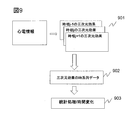
- ⁇ Second embodiment> Also in the present embodiment, the processing for calculating the blood flow velocity by two methods for the same position from the echo signal, the processing for evaluating the consistency of the blood flow velocity calculated by the two methods, and the blood flow velocity Using the process of estimating the three-dimensional effect of blood flow in the imaging region using consistency and the estimated three-dimensional effect of blood flow, the pressure difference between two points, the blood flow flux, and the tissue blood flow The process of generating diagnostic information such as acting force is the same as in the first embodiment.
- the above-described processing is performed for each time phase using the periodic motion information of the heart input from the input unit 10 or the image information obtained from the tomographic image forming unit, or features such as a systole or a diastole. It is characterized by estimating three-dimensional effects and generating diagnostic information for specific time phases.
- Periodic motion information of the heart can be performed based on an electrocardiogram. Information such as mitral valve inflow velocity, pulmonary artery reflux velocity, cardiac wall motion velocity, cardiac wall motion, and the like can also be used.
- echo signals of each time phase are obtained with reference to an electrocardiogram, and a blood flow vector of an imaging cross section is calculated from these echo signals to estimate a three-dimensional effect.
- a three-dimensional effect 901 for each time phase is obtained.
- the diagnostic information for each time phase is calculated using the three-dimensional effect 901 for each time phase.
- the various amounts calculated by the three-dimensional effect estimation unit 155 are the same as those in the first embodiment, and the spatial change rate of the blood flow velocity in the direction orthogonal to the imaging section, the various amounts calculated therefrom, and between the two points It includes diagnostic information such as pressure range, momentum and kinetic energy flux, and tissue blood flow interaction force.
- Diagnostic information 902 obtained in time series can be displayed as it is on the display unit 14 together with the electrocardiogram, thereby confirming changes in the diagnostic information accompanying the cardiac cycle. Furthermore, the transition of various quantities calculated by the three-dimensional effect estimation unit 155 may be displayed, or a statistic 903 such as a maximum value, a minimum value, or an average value within the measurement period may be calculated. (Differential value) or integral value may be calculated. Rather than obtaining time-series data, diagnostic information may be generated by selecting data of a specific time phase of interest.
- diagnostic information reflecting the three-dimensional effect can be provided as information related to the cardiac phase.
- ⁇ Display Embodiment> As described above, in the ultrasonic imaging apparatus of the present invention, various diagnostic information reflecting the three-dimensional effect can be provided, and the providing method is not particularly limited, but a typical providing method is provided. Is a method of displaying as a display image on the display unit 14 of the apparatus. The display image is generated by the display image generation unit 156.
- the display method is not limited to these, various combinations, omission of non-essential elements, etc. Is possible.
- FIG. 10 shows an example of displaying the blood flow vector three-dimensional effect.
- a black and white tomographic image here, the myocardium 31 is shown
- the blood flow velocity vector 510 are overlaid, and the three-dimensional effect (velocity in the direction orthogonal to the imaging surface) calculated in step S5 is obtained.
- (Space change rate) 520 is displayed in contour lines.
- a three-dimensional effect display unit 515 is provided, and numerical values related to the spatial change rate 520 in the vertical direction of the imaging surface, arbitrary physical quantities and their residual amounts, temporal changes, pressure difference distributions, etc. are displayed as numerical values. You may display on the part 515.
- these various quantities may be displayed as a difference or a ratio by providing a certain reference point.
- a history of the blood flow vector three-dimensional effect may be displayed, and one or more of the maximum value, the minimum value, the average value, and the variance value within one heartbeat may be displayed.
- FIG. 11 shows an example in which the pressure difference distribution 530 is displayed.
- the spatial distribution 530 of the pressure difference is displayed by superimposing black and white tomographic images.
- a certain reference point may be provided to display the difference or ratio of the pressure difference, or the pressure difference distribution history may be displayed, and the maximum value, minimum value, average value, and variance value within one heartbeat.
- One or more of these may be displayed on the three-dimensional effect display unit (515: FIG. 10).
- the value of the designated location may be displayed on the screen by the examiner designating a desired location in the image via the operation of the input unit 10 such as a mouse.
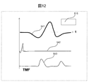
- the display example shown in FIG. 12 shows the pressure difference between two points as in FIG. 11, but here, the temporal change of the pressure difference is displayed as a graph 541.
- This graph 541 is displayed together with any information of temporal changes in myocardial movement acquired by the tomographic image forming unit, temporal changes in blood flow rate acquired by the Doppler velocity calculation unit, or external electrocardiogram information. Is preferred.
- an electrocardiogram 542 and a mitral valve inflow waveform 543 and a graph 541 of a pressure difference between two points are displayed.
- the temporal change of the myocardial movement stored in the memory 157 in advance and the temporal change of the blood flow velocity acquired by the Doppler velocity calculation unit are cut out between the electrocardiogram R wave and the R wave (between RR). (Synchronized), may be displayed.
- the movement of the myocardium may be M-mode information for acquiring a temporal change at a location desired by the examiner.
- FIG. 13 is an example in which the tissue blood flow interaction force generated by the diagnostic information generation unit 159 is displayed.
- the x-direction component 544x of the tissue blood flow interaction and the y-direction component 544y of the tissue blood flow interaction force are each displayed as a graph showing changes over time. Also in this case, it is displayed together with the electrocardiogram 542, the mitral valve inflow waveform 543, etc., but the temporal change of the myocardial movement stored in the memory 157 in advance, the blood flow velocity obtained by the Doppler velocity calculation unit.
- a temporal change may be cut out between the ECG R wave and the R wave (synchronized between RR) and displayed.
- the movement of the myocardium may be M-mode information for acquiring a temporal change at a location desired by the examiner.
- FIG. 14 is an example in which a tissue blood flow interaction force estimated based on an echo signal measured at a certain time point is displayed as a vector 545 so as to be superimposed on a black and white tomographic image. Also in this case, the three-dimensional effect display unit 515 can display a numerical value of the tissue blood flow interaction force or other various amounts.
- various displays are possible, whereby the examiner can receive information effective for diagnosis via the display unit.
- the display method is not limited to the above-described embodiment, and various combinations and omission of elements that are not essential are possible.
- the display unit is not limited to the display unit provided in the ultrasonic imaging apparatus of the present embodiment, and it is needless to say that the display unit can also display on other display devices by using various known data transfer techniques. Yes.
- the ultrasonic diagnostic apparatus capable of estimating the blood flow velocity vector from the color Doppler method information
- higher-order diagnostic information reflecting the blood flow velocity component orthogonal to the imaging cross section is provided. This can contribute to more reliable diagnosis.
Landscapes
- Health & Medical Sciences (AREA)
- Life Sciences & Earth Sciences (AREA)
- Engineering & Computer Science (AREA)
- Medical Informatics (AREA)
- Surgery (AREA)
- Pathology (AREA)
- Radiology & Medical Imaging (AREA)
- Biophysics (AREA)
- Biomedical Technology (AREA)
- Heart & Thoracic Surgery (AREA)
- Physics & Mathematics (AREA)
- Molecular Biology (AREA)
- Nuclear Medicine, Radiotherapy & Molecular Imaging (AREA)
- Animal Behavior & Ethology (AREA)
- General Health & Medical Sciences (AREA)
- Public Health (AREA)
- Veterinary Medicine (AREA)
- Computer Vision & Pattern Recognition (AREA)
- Hematology (AREA)
- Cardiology (AREA)
- Ultra Sonic Daignosis Equipment (AREA)
Abstract
Priority Applications (4)
| Application Number | Priority Date | Filing Date | Title |
|---|---|---|---|
| JP2016505096A JP6152218B2 (ja) | 2014-02-28 | 2015-01-19 | 超音波撮像装置及び方法 |
| CN201580009862.3A CN106028948B (zh) | 2014-02-28 | 2015-01-19 | 超声波摄像装置以及方法 |
| US15/121,415 US20160361040A1 (en) | 2014-02-28 | 2015-01-19 | Ultrasonic image pickup device and method |
| EP15754706.8A EP3111850A4 (fr) | 2014-02-28 | 2015-01-19 | Dispositif et procédé de capture d'image ultrasonore |
Applications Claiming Priority (2)
| Application Number | Priority Date | Filing Date | Title |
|---|---|---|---|
| JP2014038538 | 2014-02-28 | ||
| JP2014-038538 | 2014-02-28 |
Publications (1)
| Publication Number | Publication Date |
|---|---|
| WO2015129336A1 true WO2015129336A1 (fr) | 2015-09-03 |
Family
ID=54008665
Family Applications (1)
| Application Number | Title | Priority Date | Filing Date |
|---|---|---|---|
| PCT/JP2015/051281 Ceased WO2015129336A1 (fr) | 2014-02-28 | 2015-01-19 | Dispositif et procédé de capture d'image ultrasonore |
Country Status (5)
| Country | Link |
|---|---|
| US (1) | US20160361040A1 (fr) |
| EP (1) | EP3111850A4 (fr) |
| JP (1) | JP6152218B2 (fr) |
| CN (1) | CN106028948B (fr) |
| WO (1) | WO2015129336A1 (fr) |
Cited By (6)
| Publication number | Priority date | Publication date | Assignee | Title |
|---|---|---|---|---|
| JP2017051424A (ja) * | 2015-09-09 | 2017-03-16 | 東芝メディカルシステムズ株式会社 | 超音波診断装置、医用画像処理装置および医用画像処理プログラム |
| WO2018058577A1 (fr) * | 2016-09-30 | 2018-04-05 | 深圳迈瑞生物医疗电子股份有限公司 | Procédé ultrasonore d'affichage de paramètres de flux sanguin et système ultrasonore d'imagerie associé |
| JP2018166656A (ja) * | 2017-03-29 | 2018-11-01 | 株式会社日立製作所 | 超音波撮像装置及びその制御方法 |
| JP2018192174A (ja) * | 2017-05-22 | 2018-12-06 | 株式会社日立製作所 | 超音波診断装置 |
| JP2021529039A (ja) * | 2018-06-28 | 2021-10-28 | コーニンクレッカ フィリップス エヌ ヴェKoninklijke Philips N.V. | カラードップラー超音波イメージングを行うための方法及びシステム |
| CN114126495A (zh) * | 2020-04-30 | 2022-03-01 | 深圳迈瑞生物医疗电子股份有限公司 | 血流向量速度、血流频谱的处理方法及超声设备 |
Families Citing this family (23)
| Publication number | Priority date | Publication date | Assignee | Title |
|---|---|---|---|---|
| US7860555B2 (en) | 2005-02-02 | 2010-12-28 | Voyage Medical, Inc. | Tissue visualization and manipulation system |
| US9510732B2 (en) | 2005-10-25 | 2016-12-06 | Intuitive Surgical Operations, Inc. | Methods and apparatus for efficient purging |
| US11478152B2 (en) | 2005-02-02 | 2022-10-25 | Intuitive Surgical Operations, Inc. | Electrophysiology mapping and visualization system |
| US20080015569A1 (en) | 2005-02-02 | 2008-01-17 | Voyage Medical, Inc. | Methods and apparatus for treatment of atrial fibrillation |
| US9055906B2 (en) | 2006-06-14 | 2015-06-16 | Intuitive Surgical Operations, Inc. | In-vivo visualization systems |
| US20080097476A1 (en) | 2006-09-01 | 2008-04-24 | Voyage Medical, Inc. | Precision control systems for tissue visualization and manipulation assemblies |
| US10004388B2 (en) * | 2006-09-01 | 2018-06-26 | Intuitive Surgical Operations, Inc. | Coronary sinus cannulation |
| US9226648B2 (en) | 2006-12-21 | 2016-01-05 | Intuitive Surgical Operations, Inc. | Off-axis visualization systems |
| JP6152218B2 (ja) * | 2014-02-28 | 2017-06-21 | 株式会社日立製作所 | 超音波撮像装置及び方法 |
| WO2016119247A1 (fr) * | 2015-01-30 | 2016-08-04 | 深圳迈瑞生物医疗电子股份有限公司 | Système et procédé d'imagerie échographique |
| US10945700B2 (en) * | 2015-03-02 | 2021-03-16 | B-K Medical Aps | Non-invasive estimation of intravascular pressure changes using vector velocity ultrasound (US) |
| KR102439769B1 (ko) * | 2016-01-18 | 2022-09-05 | 삼성메디슨 주식회사 | 의료 영상 장치 및 그 동작방법 |
| US10499883B2 (en) * | 2017-02-17 | 2019-12-10 | General Electric Company | Methods and systems for spatial color flow for diagnostic medical imaging |
| JP6934948B2 (ja) * | 2017-09-19 | 2021-09-15 | 富士フイルム株式会社 | 流体解析装置および流体解析装置の作動方法並びに流体解析プログラム |
| JP7052313B2 (ja) * | 2017-11-20 | 2022-04-12 | コニカミノルタ株式会社 | 超音波信号処理装置、超音波診断装置、および、超音波信号処理方法 |
| US20190216430A1 (en) * | 2018-01-15 | 2019-07-18 | General Electric Company | System and method for ultrasound flow imaging |
| JP6990819B2 (ja) * | 2018-03-07 | 2022-01-12 | 富士フイルムヘルスケア株式会社 | 超音波撮像装置及び方法 |
| EP3586758A1 (fr) * | 2018-06-28 | 2020-01-01 | Koninklijke Philips N.V. | Procédés et systèmes permettant d'effectuer une quantification de pression transvalvulaire |
| CN112912762B (zh) | 2018-10-23 | 2024-09-10 | 皇家飞利浦有限公司 | 自适应超声流动成像 |
| JP7084342B2 (ja) * | 2019-03-08 | 2022-06-14 | 富士フイルムヘルスケア株式会社 | 二次流れ検出装置、二次流れ検出プログラム、及び超音波信号処理装置 |
| CN113662585B (zh) * | 2020-05-13 | 2026-03-20 | 深圳迈瑞生物医疗电子股份有限公司 | 血流成像方法以及超声成像设备 |
| CN115128299B (zh) * | 2022-08-31 | 2022-12-27 | 之江实验室 | 一种测量非透明流场的光声粒子图像测速系统和方法 |
| CN115956952B (zh) * | 2022-12-01 | 2025-11-14 | 武汉联影医疗科技有限公司 | 一种反流的监测方法和系统 |
Citations (3)
| Publication number | Priority date | Publication date | Assignee | Title |
|---|---|---|---|---|
| JP2008080106A (ja) * | 2006-08-28 | 2008-04-10 | Toshiba Corp | 超音波診断装置および超音波診断装置のデータ処理プログラム |
| JP2013176492A (ja) * | 2012-02-29 | 2013-09-09 | Hitachi Aloka Medical Ltd | 超音波診断装置 |
| WO2013157553A1 (fr) * | 2012-04-18 | 2013-10-24 | 日立アロカメディカル株式会社 | Dispositif et procédé de capture d'image ultrasonore |
Family Cites Families (14)
| Publication number | Priority date | Publication date | Assignee | Title |
|---|---|---|---|---|
| US5855557A (en) * | 1996-12-30 | 1999-01-05 | Siemens Medical Systems, Inc. | Ultrasonic imaging system and method for generating and displaying velocity field information |
| US6245017B1 (en) * | 1998-10-30 | 2001-06-12 | Kabushiki Kaisha Toshiba | 3D ultrasonic diagnostic apparatus |
| JP4269623B2 (ja) * | 2002-10-07 | 2009-05-27 | 株式会社 東北テクノアーチ | 血流可視化診断装置 |
| US8211024B2 (en) * | 2005-06-06 | 2012-07-03 | Siemens Medical Solutions Usa, Inc. | Medical ultrasound pressure gradient measurement |
| ITTO20060425A1 (it) * | 2006-06-13 | 2007-12-14 | Univ Degli Studi Torino | Metodo per la stima dell'errore di misura della velocita' di scorrimento del sangue in vasi curvilinei |
| US20080015440A1 (en) * | 2006-07-13 | 2008-01-17 | The Regents Of The University Of Colorado | Echo particle image velocity (EPIV) and echo particle tracking velocimetry (EPTV) system and method |
| CN101636113B (zh) * | 2007-04-27 | 2011-09-21 | 株式会社日立医药 | 超声波诊断装置 |
| WO2010129513A2 (fr) * | 2009-05-05 | 2010-11-11 | Robert Peter Blankfield | Évaluation de différentiel de débit systolique lorsqu'il concerne la santé cardiovasculaire |
| US9204858B2 (en) * | 2010-02-05 | 2015-12-08 | Ultrasonix Medical Corporation | Ultrasound pulse-wave doppler measurement of blood flow velocity and/or turbulence |
| US8315812B2 (en) * | 2010-08-12 | 2012-11-20 | Heartflow, Inc. | Method and system for patient-specific modeling of blood flow |
| EP2667783A2 (fr) * | 2011-01-28 | 2013-12-04 | Cardio Art Technologies Ltd. | Système, procédé et dispositif pour la détermination automatique et autonome de paramètres hémodynamiques et cardiaques utilisant des ultrasons |
| EP2514368B1 (fr) * | 2011-04-18 | 2017-09-20 | TomTec Imaging Systems GmbH | Procédé de transformation d'ensemble de données de vitesse de Doppler dans un champ de vecteur de vitesse |
| KR20130102913A (ko) * | 2012-03-08 | 2013-09-23 | 삼성메디슨 주식회사 | 조직의 이동 속도 및 방향 획득 방법 및 장치 |
| JP6152218B2 (ja) * | 2014-02-28 | 2017-06-21 | 株式会社日立製作所 | 超音波撮像装置及び方法 |
-
2015
- 2015-01-19 JP JP2016505096A patent/JP6152218B2/ja active Active
- 2015-01-19 WO PCT/JP2015/051281 patent/WO2015129336A1/fr not_active Ceased
- 2015-01-19 US US15/121,415 patent/US20160361040A1/en not_active Abandoned
- 2015-01-19 EP EP15754706.8A patent/EP3111850A4/fr not_active Withdrawn
- 2015-01-19 CN CN201580009862.3A patent/CN106028948B/zh active Active
Patent Citations (3)
| Publication number | Priority date | Publication date | Assignee | Title |
|---|---|---|---|---|
| JP2008080106A (ja) * | 2006-08-28 | 2008-04-10 | Toshiba Corp | 超音波診断装置および超音波診断装置のデータ処理プログラム |
| JP2013176492A (ja) * | 2012-02-29 | 2013-09-09 | Hitachi Aloka Medical Ltd | 超音波診断装置 |
| WO2013157553A1 (fr) * | 2012-04-18 | 2013-10-24 | 日立アロカメディカル株式会社 | Dispositif et procédé de capture d'image ultrasonore |
Non-Patent Citations (2)
| Title |
|---|
| See also references of EP3111850A4 * |
| TAKASHI OKADA ET AL.: "4. Ketsuryu no Sokudo Vector Hyoji Vector Flow Mapping(VFM", INNERVISION, vol. 29, no. 3, 25 February 2014 (2014-02-25), pages 70, XP008184609 * |
Cited By (11)
| Publication number | Priority date | Publication date | Assignee | Title |
|---|---|---|---|---|
| JP2017051424A (ja) * | 2015-09-09 | 2017-03-16 | 東芝メディカルシステムズ株式会社 | 超音波診断装置、医用画像処理装置および医用画像処理プログラム |
| WO2018058577A1 (fr) * | 2016-09-30 | 2018-04-05 | 深圳迈瑞生物医疗电子股份有限公司 | Procédé ultrasonore d'affichage de paramètres de flux sanguin et système ultrasonore d'imagerie associé |
| CN108882916A (zh) * | 2016-09-30 | 2018-11-23 | 深圳迈瑞生物医疗电子股份有限公司 | 超声血流的参数显示方法及其超声成像系统 |
| CN114848016A (zh) * | 2016-09-30 | 2022-08-05 | 深圳迈瑞生物医疗电子股份有限公司 | 超声血流的参数显示方法及其超声成像系统 |
| CN114848016B (zh) * | 2016-09-30 | 2026-03-24 | 深圳迈瑞生物医疗电子股份有限公司 | 超声血流的参数显示方法及其超声成像系统 |
| JP2018166656A (ja) * | 2017-03-29 | 2018-11-01 | 株式会社日立製作所 | 超音波撮像装置及びその制御方法 |
| JP2018192174A (ja) * | 2017-05-22 | 2018-12-06 | 株式会社日立製作所 | 超音波診断装置 |
| JP2021529039A (ja) * | 2018-06-28 | 2021-10-28 | コーニンクレッカ フィリップス エヌ ヴェKoninklijke Philips N.V. | カラードップラー超音波イメージングを行うための方法及びシステム |
| JP6998477B2 (ja) | 2018-06-28 | 2022-01-18 | コーニンクレッカ フィリップス エヌ ヴェ | カラードップラー超音波イメージングを行うための方法及びシステム |
| CN114126495A (zh) * | 2020-04-30 | 2022-03-01 | 深圳迈瑞生物医疗电子股份有限公司 | 血流向量速度、血流频谱的处理方法及超声设备 |
| CN114126495B (zh) * | 2020-04-30 | 2024-06-04 | 深圳迈瑞生物医疗电子股份有限公司 | 血流向量速度、血流频谱的处理方法及超声设备 |
Also Published As
| Publication number | Publication date |
|---|---|
| EP3111850A4 (fr) | 2017-12-27 |
| CN106028948A (zh) | 2016-10-12 |
| EP3111850A1 (fr) | 2017-01-04 |
| US20160361040A1 (en) | 2016-12-15 |
| JP6152218B2 (ja) | 2017-06-21 |
| CN106028948B (zh) | 2019-04-16 |
| JPWO2015129336A1 (ja) | 2017-03-30 |
Similar Documents
| Publication | Publication Date | Title |
|---|---|---|
| JP6152218B2 (ja) | 超音波撮像装置及び方法 | |
| Sugeng et al. | Left ventricular assessment using real time three dimensional echocardiography | |
| EP3629936B1 (fr) | Systèmes et procédés de détection et de visualisation automatiques d'un flux sanguin turbulent à l'aide de données de flux vectoriel | |
| US11864945B2 (en) | Image-based diagnostic systems | |
| US8343052B2 (en) | Ultrasonograph, medical image processing device, and medical image processing program | |
| JP5893723B2 (ja) | 超音波撮像装置及び超音波撮像方法 | |
| US9259205B2 (en) | Ultrasound image capture device, ultrasound image capture method, ultrasound image capture program | |
| US20110144495A1 (en) | Perfusion Imaging of a Volume in Medical Diagnostic Ultrasound | |
| JP5509437B2 (ja) | 超音波診断装置 | |
| CN109584350A (zh) | 医学诊断成像中的测量点确定 | |
| JP5491747B2 (ja) | 医用画像解析装置及び画像解析用制御プログラム | |
| JP2022517640A5 (fr) | ||
| CN105411624B (zh) | 一种超声三维流体成像与测速方法 | |
| JP5836735B2 (ja) | 対象体のスライス映像表示超音波診断装置およびその方法 | |
| JP6523918B2 (ja) | 超音波撮像装置 | |
| JP4870449B2 (ja) | 超音波診断装置及び超音波画像処理方法 | |
| Porras et al. | Improved myocardial motion estimation combining tissue Doppler and B-mode echocardiographic images | |
| Mohajery et al. | Automated 3D velocity estimation of natural mechanical wave propagation in the myocardium | |
| Ramalli et al. | Ultrasound imaging of cardiac fiber orientation: What are we looking at? | |
| Yamani et al. | Three‐dimensional echocardiography in evaluation of left ventricular indices | |
| Wong et al. | Medical imaging and computer-aided flow analysis of a heart with atrial septal defect | |
| Flu et al. | Three dimensional speckle tracking echocardiography: a novel approach in the assessment of left ventricular function? | |
| JP2018161318A (ja) | 光超音波画像化装置及び方法、光超音波画像化装置の制御プログラム並びに記録媒体 |
Legal Events
| Date | Code | Title | Description |
|---|---|---|---|
| 121 | Ep: the epo has been informed by wipo that ep was designated in this application |
Ref document number: 15754706 Country of ref document: EP Kind code of ref document: A1 |
|
| ENP | Entry into the national phase |
Ref document number: 2016505096 Country of ref document: JP Kind code of ref document: A |
|
| REEP | Request for entry into the european phase |
Ref document number: 2015754706 Country of ref document: EP |
|
| WWE | Wipo information: entry into national phase |
Ref document number: 15121415 Country of ref document: US Ref document number: 2015754706 Country of ref document: EP |
|
| NENP | Non-entry into the national phase |
Ref country code: DE |