WO2015133104A1 - プロジェクター及びプロジェクターの制御方法 - Google Patents
プロジェクター及びプロジェクターの制御方法 Download PDFInfo
- Publication number
- WO2015133104A1 WO2015133104A1 PCT/JP2015/001032 JP2015001032W WO2015133104A1 WO 2015133104 A1 WO2015133104 A1 WO 2015133104A1 JP 2015001032 W JP2015001032 W JP 2015001032W WO 2015133104 A1 WO2015133104 A1 WO 2015133104A1
- Authority
- WO
- WIPO (PCT)
- Prior art keywords
- projector
- light source
- posture
- light
- source device
- Prior art date
- Legal status (The legal status is an assumption and is not a legal conclusion. Google has not performed a legal analysis and makes no representation as to the accuracy of the status listed.)
- Ceased
Links
Images

Classifications
-
- H—ELECTRICITY
- H04—ELECTRIC COMMUNICATION TECHNIQUE
- H04N—PICTORIAL COMMUNICATION, e.g. TELEVISION
- H04N9/00—Details of colour television systems
- H04N9/12—Picture reproducers
- H04N9/31—Projection devices for colour picture display, e.g. using electronic spatial light modulators [ESLM]
- H04N9/3191—Testing thereof
- H04N9/3194—Testing thereof including sensor feedback
-
- G—PHYSICS
- G03—PHOTOGRAPHY; CINEMATOGRAPHY; ANALOGOUS TECHNIQUES USING WAVES OTHER THAN OPTICAL WAVES; ELECTROGRAPHY; HOLOGRAPHY
- G03B—APPARATUS OR ARRANGEMENTS FOR TAKING PHOTOGRAPHS OR FOR PROJECTING OR VIEWING THEM; APPARATUS OR ARRANGEMENTS EMPLOYING ANALOGOUS TECHNIQUES USING WAVES OTHER THAN OPTICAL WAVES; ACCESSORIES THEREFOR
- G03B21/00—Projectors or projection-type viewers; Accessories therefor
- G03B21/14—Details
- G03B21/145—Housing details, e.g. position adjustments thereof
-
- G—PHYSICS
- G03—PHOTOGRAPHY; CINEMATOGRAPHY; ANALOGOUS TECHNIQUES USING WAVES OTHER THAN OPTICAL WAVES; ELECTROGRAPHY; HOLOGRAPHY
- G03B—APPARATUS OR ARRANGEMENTS FOR TAKING PHOTOGRAPHS OR FOR PROJECTING OR VIEWING THEM; APPARATUS OR ARRANGEMENTS EMPLOYING ANALOGOUS TECHNIQUES USING WAVES OTHER THAN OPTICAL WAVES; ACCESSORIES THEREFOR
- G03B21/00—Projectors or projection-type viewers; Accessories therefor
- G03B21/14—Details
- G03B21/20—Lamp housings
-
- G—PHYSICS
- G03—PHOTOGRAPHY; CINEMATOGRAPHY; ANALOGOUS TECHNIQUES USING WAVES OTHER THAN OPTICAL WAVES; ELECTROGRAPHY; HOLOGRAPHY
- G03B—APPARATUS OR ARRANGEMENTS FOR TAKING PHOTOGRAPHS OR FOR PROJECTING OR VIEWING THEM; APPARATUS OR ARRANGEMENTS EMPLOYING ANALOGOUS TECHNIQUES USING WAVES OTHER THAN OPTICAL WAVES; ACCESSORIES THEREFOR
- G03B21/00—Projectors or projection-type viewers; Accessories therefor
- G03B21/14—Details
- G03B21/20—Lamp housings
- G03B21/2053—Intensity control of illuminating light
-
- G—PHYSICS
- G03—PHOTOGRAPHY; CINEMATOGRAPHY; ANALOGOUS TECHNIQUES USING WAVES OTHER THAN OPTICAL WAVES; ELECTROGRAPHY; HOLOGRAPHY
- G03B—APPARATUS OR ARRANGEMENTS FOR TAKING PHOTOGRAPHS OR FOR PROJECTING OR VIEWING THEM; APPARATUS OR ARRANGEMENTS EMPLOYING ANALOGOUS TECHNIQUES USING WAVES OTHER THAN OPTICAL WAVES; ACCESSORIES THEREFOR
- G03B21/00—Projectors or projection-type viewers; Accessories therefor
- G03B21/14—Details
- G03B21/20—Lamp housings
- G03B21/2066—Reflectors in illumination beam
-
- H—ELECTRICITY
- H04—ELECTRIC COMMUNICATION TECHNIQUE
- H04N—PICTORIAL COMMUNICATION, e.g. TELEVISION
- H04N9/00—Details of colour television systems
- H04N9/12—Picture reproducers
- H04N9/31—Projection devices for colour picture display, e.g. using electronic spatial light modulators [ESLM]
- H04N9/3141—Constructional details thereof
- H04N9/3144—Cooling systems
-
- H—ELECTRICITY
- H04—ELECTRIC COMMUNICATION TECHNIQUE
- H04N—PICTORIAL COMMUNICATION, e.g. TELEVISION
- H04N9/00—Details of colour television systems
- H04N9/12—Picture reproducers
- H04N9/31—Projection devices for colour picture display, e.g. using electronic spatial light modulators [ESLM]
- H04N9/3141—Constructional details thereof
- H04N9/315—Modulator illumination systems
- H04N9/3164—Modulator illumination systems using multiple light sources
Definitions
- the present invention relates to a projector and a control method of the projector.
- a projector comprising: a light source device; and a projection optical device that modulates light emitted from the light source device to form an image according to image information and enlarges and projects the image on a projection surface such as a screen.
- a projection optical device that modulates light emitted from the light source device to form an image according to image information and enlarges and projects the image on a projection surface such as a screen.
- the light emitting tube has a light emitting portion having a substantially spherical shape, and a pair of sealing portions extending in the direction away from each other from both ends of the light emitting portion.
- the upper end in the vertical direction of the light emitting portion is at a high temperature
- the lower end is at a lower temperature than the upper end.
- the projector has a bottom-to-bottom correct posture (standing posture) or a reverse posture (top suspension posture) in which the vertical posture is reversed. Even when installed, a projector provided with a light source device configured to guide cooling air to the upper end portion has been proposed (see, for example, Patent Document 1).
- the projector may be used in other installation postures, such as a vertical posture in which the bottom face faces sideways, in addition to the normal posture and the reverse posture.
- the installation attitude of the projector changes, the position corresponding to the upper end in the vertical direction of the light emitting unit changes according to the installation attitude.
- the position corresponding to the upper end also changes by about 90 degrees according to the rotation of the projector. Therefore, in the projector described in Patent Document 1, the cooling air can not be efficiently guided to the upper end portion of the light emitting unit in the vertical posture, and there is a possibility that the light emitting tube can not be properly cooled.
- a light source device suitable for the installation posture such as a light source device suitable for the case where the installation posture of the projector is the vertical posture.
- the light source device is kept on even though the light source device suitable for the installation posture of the projector is not mounted. This may cause a problem of shortening the life of the arc tube.
- An object of the present invention is to provide a projector that can notify of the suitability of a light source device and a control method of the projector.
- a projector is a projector that includes a light source device, a light modulation device that modulates light emitted from the light source device, and projection optics that projects light modulated by the light modulation device. It is determined that a device and a determination unit that determines whether or not a light source device that does not correspond to the installation orientation of the projector is attached, and the determination unit that a light source device that does not correspond to the installation orientation is attached And a notification unit for notifying information according to the determination result.
- a light source device that does not correspond to the installation posture of the projector can include a light source device that is lower than the original cooling efficiency and lighting efficiency when mounted on the projector installed in the installation posture.
- the notification of information according to the determination result can be exemplified by display of characters and symbols according to the determination result, output of a predetermined sound, lighting of an indicator, and the like.
- the determination unit determines whether or not the light source device that is not in accordance with the installation posture is attached, and when it is determined that the light source device is attached, the notification unit responds to the determination result. Broadcast information. According to such a configuration, it is possible to notify the user that the light source device not suitable for the installation posture of the current projector is mounted. For this reason, although the light source device which is not suitable for the present installation posture is mounted, it can suppress that a projector is continuously used. Therefore, it is possible to suppress the deterioration of the life of the light source device and the light emission luminance.
- the posture detection unit that detects the installation posture is provided, and the determination unit make the determination based on a detection result by the posture detection unit.
- the determination unit executes the determination process based on the installation posture of the projector detected by the posture detection unit. According to this, it is possible to determine whether or not the light source device not suitable for the current installation posture of the projector is mounted, without the user performing a complicated operation such as manually inputting the installation posture. Therefore, the operation of the projector can be simplified.
- the posture detection unit has a gravity sensor. According to the first aspect, since the posture detection unit has the gravity sensor, the installation posture of the projector can be appropriately detected based on the detected vertical direction, whereby the appropriate determination of the light source device can be performed.
- the luminance reduction of the light source device determined not according to the installation posture when it is determined by the determination unit that the light source device not attached according to the installation posture is mounted, the luminance reduction of the light source device determined not according to the installation posture, and It is preferable to provide a lighting control unit that performs any one of power-off of the light source. According to the first aspect, either the luminance reduction or the power-off of the light source device determined not to correspond to the installation posture is performed by the lighting control unit. Thus, the temperature of the light source device can be lowered, so that it is possible to more reliably suppress shortening of the life of the light source device by turning on the light source device not suitable for the installation posture.
- the installation posture is a first posture in which the bottom surface portion of the projector faces either downward or upward, and a projection direction identical to the first posture, and the bottom surface portion is lateral It is preferable to include the 2nd attitude
- the same projection direction means, for example, a state in which an image is projected on a projection surface at the same position in each of the first attitude and the second attitude.
- the determination unit is mounted with the light source device which does not correspond to the installation posture of the projector including the first posture (the normal posture or the reverse posture) and the second posture (the vertical posture). It is judged whether it is done or not.
- the light source device suitable for the second posture when the light source device suitable for the second posture is attached to the projector installed in the first posture, or the posture of the projector is rotated 90 degrees from the first posture.
- the light source device suitable for the first posture is attached to the projector installed in the second posture, information according to the determination result can be notified. Therefore, it is possible to notify the mounting of the light source device which is not suitable for the current installation posture of the projector.
- the light source device is attached to the light emitting unit having a light emitting unit that emits a discharge light and a light emitting tube having a sealing unit extending from the light emitting unit, and is incident from the light emitting unit A reflecting mirror that reflects light in a direction opposite to the extending direction of the sealing unit from the light emitting unit and emits the light to the outside of the light source device, and among the first attitude and the second attitude
- One of the installation postures is that the light emission direction of the light from the light source device is along the horizontal direction, and the other installation posture is that the light emission direction of the light from the light source device is along the vertical direction preferable.
- the light emission direction is along the horizontal direction, it seems that the light emission direction is substantially the same as the horizontal direction although it is slightly inclined with respect to the horizontal direction. And the case of being substantially horizontal. The same applies to the case where the light emission direction is along the vertical direction.
- the position of the upper end in the vertical direction at which the temperature is highest in the light emitting unit, when the direction of the light emitted from the light source device follows the horizontal direction and when the direction of the light follows the vertical direction Because of the difference, it is necessary to change the blowing direction and the air flow rate of the air for cooling the upper end.
- the light source unit used in the projector with the installation direction in which the emission direction is in the vertical direction is attached to the projector installed in the installation posture in which the emission direction of the light from the light source device is in the horizontal direction
- the notification unit notifies that the light emitting tube is easily deteriorated. It can be informed. Therefore, lighting of the light source device which is not suitable for the installation posture is continued, and the life of the light source device can be further reliably suppressed from being reduced.
- a control method of a projector according to a second aspect of the present invention is a control method of a projector that modulates and projects a light flux emitted from a light source device, and a light source device not attached to the installation posture of the projector is mounted If it is determined that the light source device which is not in accordance with the installation posture is attached, information according to the determination result is notified.
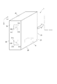
- FIG. 1 is a schematic view showing an appearance configuration of a projector according to an embodiment of the present invention.
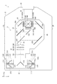
- FIG. 2 is a schematic view showing an internal configuration of a projector in the embodiment.
- FIG. 2 is a schematic view showing the projector in the vertical posture in the embodiment.
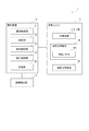
- FIG. 2 is a block diagram showing an internal configuration of a projector in the embodiment. The flowchart which shows the error detection process in the said embodiment. The schematic diagram which shows the modification of the said embodiment.
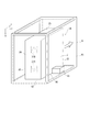
- FIG. 1 is a schematic view showing an appearance configuration of a projector 1 according to the present embodiment.
- the projector 1 projects an image according to the image information onto a projection surface (not shown) such as a screen and displays the image.
- the projector 1 includes an exterior housing 2 that constitutes an exterior.
- the exterior housing 2 is a housing made of metal or synthetic resin, and includes a top surface 21 and a bottom surface 22 facing each other, a front surface 23, a back surface 24, a right side surface 25, and a left surface 26.
- the bottom portion 22 is a surface facing the setting surface when the projector 1 is mounted on the setting surface such as a setting table, and the bottom portion 22 is a leg that contacts the setting surface. (Not shown) is provided.
- the posture in which the projector 1 is installed (mounted) such that the bottom surface portion 22 faces the installation surface is referred to as a normal posture.
- position in which the projector 1 is installed so that the said bottom face part 22 may face a ceiling surface is called reverse installation attitude
- the projected images in the normal posture and the reverse posture are horizontally long images, as indicated by the rectangles of dashed dotted lines.
- the front part 23 and the back part 24 are located on the front side and the back side of the exterior housing 2 in the above-mentioned normal posture.
- the optical unit 3 is comprised, and the projection optical apparatus 35 which projects an image is exposed through an opening part.
- the right side surface portion 25 and the left side surface portion 26 are located on the right side and the left side of the exterior housing 2 in the normal posture.
- the projection direction of the image by the optical unit 3 is assumed to be the Z direction, and directions orthogonal to the Z direction and orthogonal to each other are the X direction and the Y direction.
- the Y direction is the direction (the direction from the bottom surface portion 22 toward the top surface portion 21) facing upward when the projector is installed in the normal posture
- the X direction is the projector in the normal posture Is a direction from right to left (a direction from the right side 25 to the left side 26) as viewed from the front side.
- FIG. 2 is a schematic view showing an internal configuration of the projector 1.
- the projector 1 includes an optical unit 3 housed inside the exterior housing 2 in addition to the exterior housing 2.
- the optical unit 3 forms and projects an image according to image information under the control of the control device 5 described later.
- the optical unit 3 includes a pair of light source devices 31A and 31B, a reflection mirror 31C, an illumination optical device 32, a color separation optical device 33, an electro-optical device 34, and a projection optical device 35.
- an optical component casing 36 is a casing that accommodates the light source devices 31A and 31B, the reflection mirror 31C, and the optical devices 32 to 34 therein.
- the pair of light source devices 31A and 31B are disposed opposite to each other with the reflection mirror 31C interposed therebetween so as to emit light beams toward the reflection mirror 31C.
- the reflection mirror 31C reflects the light incident from the light source devices 31A and 31B in the same direction, thereby causing the light to be incident on the illumination optical device 32.
- the illumination optical device 32 includes lens arrays 321 and 322, a polarization conversion element 323, and a superimposing lens 324.
- the color separation optical device 33 has dichroic mirrors 331 and 332 and reflection mirrors 333-336.
- the electro-optical device 34 includes three liquid crystal panels 341 as light modulators (the liquid crystal panel on the red light side is 341R, the liquid crystal panel on the green light side is 341G, and the liquid crystal panel on the blue light side is 341B), and three incident It has a side polarization plate 342, three emission side polarization plates 343, and a cross dichroic prism 344 as a color combining optical device.
- the light beams emitted from the pair of light source devices 31A and 31B are the illumination light axis Ax (FIG. 2) set inside the optical component casing 36 by the reflection mirror 31C.
- the light is reflected to the illumination optical device 32.
- the luminous flux emitted to the illumination optical device 32 is equalized in in-plane illuminance by the illumination optical device 32 and separated into three color lights of R, G and B by the color separation optical device 33.
- the separated color lights are respectively modulated by the liquid crystal panels 341 according to the image information, and an image for each color light is formed.
- the image for each color light is synthesized by the cross dichroic prism 344 and projected on a screen (not shown) by the projection optical device 35.
- the pair of light source devices 31A and 31B includes a light source lamp 311 having a light emitting tube 312 and a reflector 315 corresponding to the reflecting mirror of the present invention, and a storage body for housing the light source lamp 311 inside. And 316.
- the light emitting tube 312 bulges in a substantially spherical shape, and a light emitting portion 313 in which a light emitting material such as mercury is enclosed, and a pair of sealing portions extending in the direction away from each other from both ends of the light emitting portion.
- the light source lamp 311 is configured by attaching the reflector 315 to one sealing portion 314, and is disposed inside the storage body 316.
- the light from the light emitting unit 313 is reflected by the reflector 315 in a direction (direction from the sealing unit 314 toward the light emitting unit 313) opposite to the extending direction of the sealing unit 314 to which the reflector 315 is attached. That is, in each of the light source devices 31A and 31B, the light emission direction is a direction along the central axis of the light emitting tube 312.
- Such light source devices 31A and 31B are exchangeably mounted in the exterior housing 2.
- FIG. 3 is a view schematically showing the projector 1 installed in a portrait orientation corresponding to so-called portrait mode projection.
- the relationship between the installation posture of the projector 1 and the direction along the central axis of the light emitting tube 312, that is, the light emission direction will be described.
- the central axes of the light emitting tubes 312 of the light source devices 31A and 31B are along the horizontal direction.
- FIG. 3 when the projector 1 is installed in a vertical orientation in which the bottom surface portion 22 faces sideways and the right side surface portion 25 faces upward, each of the light source devices 31A and 31B
- the central axis of the light emitting tube 312 is along the vertical direction.
- the position of such an upper end changes depending on the attitude of the projector 1. For example, in the normal placement posture and the reverse placement posture, since the central axis of the light emitting tube 312 is in the horizontal direction, the position of the upper end portion is substantially at the upper center in the direction along the central axis of the light emitting portion 313.
- the central axis of the light emitting tube is in the vertical direction in the above-described vertical posture, the position of the upper end portion is biased toward the one sealing portion 314 side. Therefore, it is necessary to change the blowing direction and the air volume of the air for cooling the light emitting tube 312 in accordance with the installation posture of the projector 1.
- the storage body 316 is capable of blowing a suitable amount of cooling air in the appropriate blowing direction to the light emitting tube 312 according to the installation posture of the projector 1, ie, the installation posture of the light emitting tube 312.
- FIG. 4 is a block diagram showing an internal configuration of the projector 1 including the posture detection unit 4 and the control device 5.
- the projector 1 further includes an attitude detection unit 4 and a control device 5 as shown in FIG.
- the posture detection unit 4 has a gravity sensor, and detects the installation posture of the projector 1 based on the detection result of the gravity sensor.
- the posture detection unit 4 is configured to be able to detect a normal placement posture, a reverse placement posture, and a vertical placement posture as the installation posture of the projector 1 based on the detection result.
- the control device 5 is configured by hardware such as a central processing unit (CPU), a random access memory (RAM), and a flash memory, and controls the operation of the projector 1. For example, the control device 5 controls the optical unit 3 to form and project an image according to the image information. Further, the control device 5 determines whether or not the light source devices 31A and 31B having specifications not suitable for the installation posture of the projector 1 are mounted, and controls the optical unit 3 to notify the user of the information according to the determination result. Do. Therefore, as shown in FIG. 4, the control device 5 has a storage unit 55 configured by the above-described RAM and flash memory, as well as a type acquisition unit 51, a determination unit 52, a display control unit 53 and a lighting control unit 54. It has as a functional part.
- a storage unit 55 configured by the above-described RAM and flash memory
- the type acquisition unit 51 acquires the type of the light source devices 31A and 31B from the light source devices 31A and 31B mounted on the projector 1. For example, from the storage unit (not shown) provided in the mounted light source devices 31A and 31B, the type acquisition unit 51 determines whether the light source devices 31A and 31B are light source devices for the normal placement posture and the reverse placement posture, Alternatively, identification information indicating whether it is a light source device for the vertical posture is acquired. In addition, a switch is provided not only in such a configuration but at the attachment site of the light source devices 31A and 31B, and the type acquisition unit 51 determines the light source for the normal posture and the reverse posture depending on whether the switch is pressed. It may be configured to acquire identification information indicating whether it is a device or a light source device for vertical posture.
- the determination unit 52 grasps the installation posture of the projector 1 based on the detection result of the posture detection unit 4. Then, the determination unit 52 determines whether or not the light source devices 31A and 31B that do not correspond to the installation posture are attached. For example, when the installation posture of the projector 1 is a normal posture, and each of the light source devices 31A and 31B is a light source device for a normal posture, it is determined that there is no light source device not corresponding to the installation posture. On the other hand, when the installation posture of the projector 1 is normal posture and at least one of the light source devices 31A and 31B is not a light source device for normal posture, it is determined that the light source device not attached to the installation posture is attached. Do. The same applies to the case where the installation attitude of the projector 1 is the vertical installation attitude.
- the display control unit 53 drives the liquid crystal panel 341 according to the image information, and forms and displays an image according to the image information.
- the display control unit 53 causes the projector 1 to display an error notification image when the determination unit 52 determines that the light source device that is not in accordance with the installation posture of the projector 1 is attached.
- Such an error notification image includes, for example, information indicating that a light source device not suitable for the installation posture of the projector 1 is attached, and information indicating which light source device is not suitable.
- the error notification image can be displayed by, for example, an OSD (On Screen Display).
- Such a display control unit 53 corresponds to a notification unit of the present invention.
- the lighting control unit 54 controls lighting states (lighting and extinguishing, light emission luminance at lighting, and the like) of the light source devices 31A and 31B. Further, when it is determined by the determination unit 52 that the light source device not attached to the installation posture of the current projector 1 is mounted, the lighting control unit 54 changes the lighting luminance of the light source device according to the installation posture Lower than when the light source device is mounted, or turn off the light source device.
- the storage unit 55 stores various programs and data required to control the projector 1.
- the storage unit 55 stores a control program for executing an error detection process (see FIG. 5) described later, and the CPU acquires the type acquisition unit 51 and the determination unit 52 by executing the control program.
- the display control unit 53 and the lighting control unit 54 are realized.
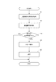
- FIG. 5 is a flowchart showing an example of the error detection process.
- the CPU of the control device 5 executes an error detection program stored in the storage unit 55 to carry out an error detection process described below.
- this process is performed when the power of the projector 1 is turned on (at the time of startup) or the like, but may be performed at a predetermined timing such as a timing according to a user operation.
- the type acquisition unit 51 acquires the type of the light source devices 31A and 31B (step S1). That is, the type acquisition unit 51 acquires identification information indicating whether the light source devices 31A and 31B are light source devices for the normal posture and the reverse posture or for the vertical posture.
- the posture detection unit 4 detects the installation posture of the projector 1, and the determination unit 52 grasps the installation posture of the projector 1 based on the detection result by the posture detection unit 4 (step S2).
- the determination unit 52 determines whether a light source device having a specification not suitable for the installation posture of the projector 1 is attached (step S3). That is, based on the types of light source devices 31A and 31B and the installation posture of the projector 1, the determination unit 52 determines whether or not the light source devices 31A and 31B not attached to the current installation posture are mounted.
- the display control unit 53 causes the projector 1 to make an error based on the determination result.
- the notification image is displayed for a predetermined period (step S4).
- the lighting control unit 54 and the light source devices 31A and 31B are turned off (step S5).
- the error detection process by the control device 5 ends. In this case, as a result of the error detection process, an error is detected and the light source devices 31A and 31B are turned off. Therefore, the projector 1 maintains the standby state or the power is turned off.
- step S3 when it is determined in step S3 that the light source device having a specification not suitable for the installation posture of the projector 1 is not mounted by the determination unit 52 (step S3; NO), the error detection process by the control device 5 ends. . Then, in the projector 1, normal processing (for example, image display processing by the display control unit 53) by the control device 5 is performed.
- normal processing for example, image display processing by the display control unit 53
- the determination unit 52 determines whether or not the light source device that does not correspond to the installation posture is attached, and when it is determined that the light source device is attached, the display control unit 53 reports an error as information according to the above determination result. By displaying the image, the user is notified of the detection of an error. According to such a configuration, it is possible to notify the user that the light source device not suitable for the current installation posture of the projector 1 is mounted. For this reason, although the light source device which is not suitable for the present installation posture is mounted, it can suppress that the projector 1 is continuously used. Therefore, it is possible to suppress a decrease in the lifetime of the light source devices 31A and 31B and the light emission luminance.
- the determination unit 52 executes the above-described determination process based on the installation posture of the projector detected by the posture detection unit 4. According to this, it is possible to determine whether or not the light source device not suitable for the current installation posture of the projector 1 is mounted without performing a complicated operation such as the user manually inputting the installation posture, for example. Therefore, the operation of the projector 1 can be simplified. Further, since the posture detection unit 4 has a gravity sensor, the installation posture of the projector 1 can be appropriately detected based on the detected vertical direction, whereby the appropriate determination of the light source device can be performed.
- the orientation (light emission direction) of the central axis of the light emitting tube 312 with respect to the vertical direction can be appropriately detected, and the mounted light source devices 31A and 31B are light source devices suitable for the current installation posture. Can be determined more accurately. That is, in the light source devices 31A and 31B, the upper end portion of the light emitting unit 313 in the vertical direction has the highest temperature. Therefore, the light source devices 31A and 31B are light source devices having a structure for blowing air of a blowing direction and an air volume capable of appropriately cooling the upper end portion with respect to the current installation posture, and suitable for the current installation posture Can be determined more accurately based on the detected vertical direction.
- the lighting control unit 54 turns off the power of the light source devices 31A and 31B.
- the light source device not suitable for the installation posture is turned on, and the decrease in the life of the light source device can be more reliably suppressed.
- the determination unit 52 determines whether or not the light source device not attached to the installation posture of the projector 1 including the normal posture, the reverse posture, and the vertical posture is mounted.
- the light source device suitable for the vertical mounting posture is attached to the projector 1 installed in the normal mounting posture or the reverse mounting posture, or the posture of the projector 1 is 90 degrees from the normal mounting posture or the reverse mounting posture
- the light source device suitable for the normal posture or the reverse posture is attached to the projector installed in the rotated vertical posture, information according to the determination result can be notified. Therefore, it is possible to notify the mounting of the light source device which is not suitable for the installation posture of the projector 1 at present.
- the light source devices 31A and 31B include a light emitting unit 313 that emits a discharge light, and a light emitting tube 312 having a sealing unit 314 extending from the light emitting unit 313.
- the central axis (light emission direction) of the light source is in a posture along the horizontal direction
- the vertical posture is a posture in which the central axis of the light emitting tube 312 is along the vertical direction.
- the position of the upper end in the vertical direction where the temperature is the highest is different in the light emitting portion 313 between the case where the central axis of the light emitting tube 312 extends in the horizontal direction and the case where the central axis extends in the vertical direction.
- the display control unit 53 performs the display processing (notification processing) of the error notification image.
- the user can be reliably notified of a state in which the light emitting tube 312 tends to deteriorate. Therefore, lighting of the light source device which is not suitable for the installation posture is continued, and the life of the light source device can be further reliably suppressed from being reduced.
- FIG. 6 is a view schematically showing an example of a configuration in which a posture detection unit is provided outside the projector. As shown in FIG. 6, the projector 1A and the posture detection unit 4A are integrally held by the frame 6.
- the frame 6 has a frame 61 surrounding the projector 1A, and a base 62 for fixing the projector 1A and the posture detection unit 4A to the frame 61.
- the frame 6 is formed of, for example, a material having a desired strength, such as a metal material.
- the projector 1A has the same configuration as the projector 1 of the above embodiment except that the posture detection unit 4 is not provided.
- the posture detection unit 4A has the same configuration as the posture detection unit 4, and is communicably connected to the projector 1A.
- the attitude detection unit 4A transmits the detected installation attitude to the projector 1A. As described above, by integrally fixing the projector 1A and the posture detection unit 4A to the frame 6, based on the detection result of the posture detection unit 4A provided outside the projector 1A, the installation posture of the projector 1A is suitable. It is possible to detect the mounting of the light source device.
- the frame 6 in the case of using the projector in the vertical orientation is shown as an example.
- a frame specifying unit that causes the projector 1A to detect that the frame is fixed to the vertically oriented attitude frame 6 is used. You may provide.
- the frame specifying unit instead of the installation posture of the projector 1 transmitted by the posture detection unit 4A, the frame specifying unit outputs information indicating the vertical posture to the projector 1A. Even with such a configuration, the projector 1A can detect the mounting of the light source device that is not suitable for the installation posture. The same applies to the frames for other installation postures such as the normal posture and the reverse posture.
- a configuration in which the projector 1A is rotatably held with respect to the frame 6 may be employed.
- the base to which the projector 1A is fixed may be rotatably held with respect to the frame portion.
- a posture detection unit that detects the installation posture of the projector
- a detection device such as an optical sensor that detects the rotation direction and the rotation amount of the projector with respect to the frame may be adopted.
- the present invention is not limited to the configuration that allows the projector to detect the installation posture, such as the posture detection unit and the frame identification unit.
- the user may be configured to be able to input the installation attitude of the projectors 1 and 1A using an input device such as an operation panel provided on a part of the projectors 1 and 1A or a remote controller (not shown).
- the determination unit 52 acquires the installation posture of the projector 1 and the identification information of the light source devices 31A and 31B, and uses the acquired installation posture and identification information to mount the light source device not suitable for the installation posture. It has been determined whether or not it is not limited to this.
- the identification information of the light source device according to the current installation posture is stored in the storage unit 55, and the stored identification information and the identification information of the light source devices 31A and 31B are acquired to be suitable for the installation posture. It may be determined whether or not the light source device is mounted.
- the error notification image when an error is detected in the error detection process, the error notification image is displayed for a predetermined period, and then the light source devices 31A and 31B are turned off.
- the present invention is limited to this. Absent. For example, the lighting brightness of the light source devices 31A and 31B may be lowered than in the normal state.
- the error notification image may be displayed for a predetermined period, and the light source devices 31A and 31B may not be turned off, and thereafter, a normal image may be displayed. Further, the error notification image may be continuously displayed, or the error notification image may be deleted according to the user's operation.
- the error notification image is not limited to the image projected by the projector 1.
- the error notification image may be displayed on a display device provided in the projector 1 or 1A or a remote controller.
- reporting image was illustrated as a alerting
- a status lamp for notifying an error by lighting a lamp provided on the main body of the projector 1 may be adopted, or an audio output apparatus for notifying the judgment result by the judgment unit 52 by voice may be adopted. .
- the said embodiment provided the structure provided with two light source device 31A, 31B, this invention is not limited to this.
- one light source device may be provided, or three or more light source devices may be provided.
- the light source devices 31A and 31B exemplarily have a configuration in which the central axis of the light emitting tube 312 is in the horizontal direction in the normal orientation (reverse orientation) and in the vertical orientation. Is not limited to this. That is, although the light emission directions of the light source devices 31A and 31B are in the horizontal direction in the normal posture (reverse posture) and the vertical direction in the vertical posture, respectively, the present invention is limited thereto. Absent.
- the light source devices 31A and 31B may have a configuration in which the central axis of the light emitting tube 312 is along the vertical direction in the normal orientation (reverse orientation) and along the horizontal direction in the vertical orientation.
- the central axis of the light emitting tube 312 may be configured to extend in the horizontal direction in both the normal posture (reverse posture) and the vertical posture. Also in such a case, the position of the upper end portion of the light emitting unit 313 in the vertical direction (the position at which the temperature is the highest) changes depending on the posture of the projector 1 as in the above embodiment. Therefore, even in such a case, the light emitting unit 313 needs to be cooled according to the posture, so the present invention can be suitably applied. The same applies to the configuration of the light source devices 31A and 31B in which the central axis of the light emitting tube 312 extends in the vertical direction in both the normal posture (reverse posture) and the vertical posture.
- the light source devices 31A and 31B are arranged to emit light in the directions facing each other, but the present invention is not limited to this. That is, the light source devices 31A and 31B may be arranged to emit light in the same direction (for example, the Z direction).
- the two light source devices 31A and 31B are light source devices according to the same installation posture (for example, the normal posture and the reverse posture) in the above embodiment, the present invention is not limited thereto. That is, when two or more light source devices are provided, the light source devices may not all correspond to the same installation posture, and the light source devices may be used in combination in different installation postures. When light source devices corresponding to different installation postures are used in combination, only the light source devices corresponding to the current installation posture may be lit. Further, in this case, the light source device which does not correspond to the current installation posture may be configured to be turned on while reducing the luminance.
- the light source device for the normal posture and the reverse posture and the light source device for the vertical posture are arranged such that the light emission device having the same specifications has the light emission direction according to each installation posture. Therefore, the light source device may be used as a light source device according to each installation posture.
- the projector 1 is configured to include the three liquid crystal panels 341 as the light modulation device in the above embodiment, the present invention is not limited to this. That is, the present invention is also applicable to a projector including two or less or four or more liquid crystal panels as light modulation devices.
- the optical unit 3 is configured to have the shape shown in FIG. 2 in the above embodiment, the present invention is not limited to this, and for example, a configuration having a substantially L shape in plan view or a substantially U shape in plan view is adopted May be
- the light modulation apparatus which has a transmissive liquid crystal panel in which a light-incidence surface and a light-projection surface differ is employ
- the present invention is not limited to this, and a reflection type light modulation device having a reflection type liquid crystal panel in which the light incident surface and the light emission surface are the same may be adopted.
- devices using micro mirrors for example, devices using DMD (Digital Micromirror Device), etc. other than liquid crystal A light modulator may be used.
Landscapes
- Engineering & Computer Science (AREA)
- Multimedia (AREA)
- Signal Processing (AREA)
- Physics & Mathematics (AREA)
- General Physics & Mathematics (AREA)
- Projection Apparatus (AREA)
- Transforming Electric Information Into Light Information (AREA)
Abstract
光源装置の適否を報知できるプロジェクター及びプロジェクターの制御方法を提供する。プロジェクター(1)は、光源装置(31A,31B)と、光源装置(31A,31B)から出射された光を変調する光変調装置(341)と、光変調装置により変調された光を投射する投射光学装置(35)と、当該プロジェクター(1)の設置姿勢に応じていない光源装置が装着されているか否かを判定する判定部(52)と、判定部(52)により設置姿勢に応じていない光源装置が装着されていると判定されると、判定結果に応じた情報を報知する報知部(53)とを備える。
Description
本発明は、プロジェクター及びプロジェクターの制御方法に関する。
従来、光源装置と、当該光源装置から出射された光を変調して、画像情報に応じた画像を形成し、当該画像をスクリーン等の投射面上に拡大投射する投射光学装置と、を備えるプロジェクターが知られている。
ところで、プロジェクターに採用される光源装置として、超高圧水銀ランプ等の発光管を備えた構成が知られている。この発光管は、略球状を有する発光部と、当該発光部の両端から互いに離間する方向に延出する一対の封止部と、を有している。このような発光管の点灯時には、発光部の鉛直方向における上端部が高温となり、下端部は上端部に比べて低温となる。そして、発光部の上端部の高温状態が継続すると失透が生じやすくなる一方で、上端部と下端部との温度差が大きくなると黒化が生じやすくなり、発光管が劣化しやすくなる。
ところで、プロジェクターに採用される光源装置として、超高圧水銀ランプ等の発光管を備えた構成が知られている。この発光管は、略球状を有する発光部と、当該発光部の両端から互いに離間する方向に延出する一対の封止部と、を有している。このような発光管の点灯時には、発光部の鉛直方向における上端部が高温となり、下端部は上端部に比べて低温となる。そして、発光部の上端部の高温状態が継続すると失透が生じやすくなる一方で、上端部と下端部との温度差が大きくなると黒化が生じやすくなり、発光管が劣化しやすくなる。
このような問題に対し、プロジェクターの底面部が下方を向く正置き姿勢(据置き姿勢)と、当該正置き姿勢とは上下を逆にした逆置き姿勢(天吊り姿勢)とのいずれの姿勢で設置された場合でも、上記上端部に冷却風を導くように構成された光源装置を備えたプロジェクターが提案されている(例えば、特許文献1参照)。
ところで、プロジェクターは、正置き姿勢や逆置き姿勢以外にも、底面部が側方を向く縦置き姿勢等の他の設置姿勢で利用されることがある。そして、プロジェクターの設置姿勢が変化すると、当該設置姿勢に応じて、発光部の鉛直方向における上端部に相当する位置が変化する。例えば、正置き姿勢及び逆置き姿勢からプロジェクターを約90度回転させて縦置き姿勢とした場合、当該上端部に相当する位置もプロジェクターの回転に応じて約90度変化する。このため、特許文献1に記載のプロジェクターでは、縦置き姿勢における発光部の上記上端部に冷却風を効率よく導くことができず、発光管を適切に冷却することができないおそれがある。
このため、例えば、プロジェクターの設置姿勢が上記縦置き姿勢である場合に適した光源装置等、当該設置姿勢に適した光源装置を採用することが考えられる。しかしながら、プロジェクターの利用時には、内部にどのような光源装置が装着されているかを判断できないため、プロジェクターの設置姿勢に適した光源装置が装着されていないにも関わらず、当該光源装置を点灯させ続けることにより発光管の寿命が短くなるという問題が発生するおそれがある。
本発明は、光源装置の適否を報知できるプロジェクター及びプロジェクターの制御方法を提供することを1つの目的とする。
本発明の第1態様に係るプロジェクターは、プロジェクターであって、光源装置と、前記光源装置から出射された光を変調する光変調装置と、前記光変調装置により変調された光を投射する投射光学装置と、当該プロジェクターの設置姿勢に応じていない光源装置が装着されているか否かを判定する判定部と、前記判定部により前記設置姿勢に応じていない光源装置が装着されていると判定されると、判定結果に応じた情報を報知する報知部と、を備えることを特徴とする。
なお、プロジェクターの設置姿勢に応じていない光源装置とは、例えば、当該設置姿勢で設置されたプロジェクターに装着された場合に、本来の冷却効率や点灯効率より低下する光源装置を挙げることができる。
また、判定結果に応じた情報の報知とは、判定結果に応じた文字や記号の表示や、所定の音声の出力、インジケーターの点灯等を例示できる。
また、判定結果に応じた情報の報知とは、判定結果に応じた文字や記号の表示や、所定の音声の出力、インジケーターの点灯等を例示できる。
上記第1態様によれば、判定部は、設置姿勢に応じていない光源装置が装着されているか否かを判定し、装着されていると判定された場合、報知部は、上記判定結果に応じた情報を報知する。
このような構成によれば、現在のプロジェクターの設置姿勢に適さない光源装置が装着されていることをユーザーに報知できる。このため、現在の設置姿勢に適さない光源装置が装着されているにもかかわらず、プロジェクターが継続して利用されることを抑制できる。従って、光源装置の寿命及び発光輝度の低下を抑制できる。
このような構成によれば、現在のプロジェクターの設置姿勢に適さない光源装置が装着されていることをユーザーに報知できる。このため、現在の設置姿勢に適さない光源装置が装着されているにもかかわらず、プロジェクターが継続して利用されることを抑制できる。従って、光源装置の寿命及び発光輝度の低下を抑制できる。
上記第1態様では、前記設置姿勢を検出する姿勢検出部を備え、前記判定部は、前記姿勢検出部による検出結果に基づいて判定することが好ましい。
上記第1態様によれば、判定部は、姿勢検出部によって検出されたプロジェクターの設置姿勢に基づいて、上記判定処理を実行する。これによれば、例えば設置姿勢をユーザーが手動で入力する等の煩雑な操作を行わなくても、プロジェクターの現在の設置姿勢に適さない光源装置が装着されているか否かを判定できる。従って、プロジェクターの操作を簡略化できる。
上記第1態様によれば、判定部は、姿勢検出部によって検出されたプロジェクターの設置姿勢に基づいて、上記判定処理を実行する。これによれば、例えば設置姿勢をユーザーが手動で入力する等の煩雑な操作を行わなくても、プロジェクターの現在の設置姿勢に適さない光源装置が装着されているか否かを判定できる。従って、プロジェクターの操作を簡略化できる。
上記第1態様では、前記姿勢検出部は、重力センサーを有することが好ましい。
上記第1態様によれば、姿勢検出部が重力センサーを有するので、検出される鉛直方向に基づいてプロジェクターの設置姿勢を適切に検出でき、これにより、光源装置の適正判定を実施できる。
上記第1態様によれば、姿勢検出部が重力センサーを有するので、検出される鉛直方向に基づいてプロジェクターの設置姿勢を適切に検出でき、これにより、光源装置の適正判定を実施できる。
上記第1態様では、前記判定部により前記設置姿勢に応じていない光源装置が装着されていると判定されると、前記設置姿勢に応じていないと判定された前記光源装置の輝度低減、及び前記光源の電源のオフのいずれかを実施する点灯制御部を備えることが好ましい。
上記第1態様によれば、点灯制御部によって、設置姿勢に応じていないと判定された光源装置の輝度低減及び電源のオフのいずれかを実施する。これにより、光源装置の温度を下げることができるので、設置姿勢に適さない光源装置が点灯されて、当該光源装置の寿命が短縮されることを、より確実に抑制できる。
上記第1態様によれば、点灯制御部によって、設置姿勢に応じていないと判定された光源装置の輝度低減及び電源のオフのいずれかを実施する。これにより、光源装置の温度を下げることができるので、設置姿勢に適さない光源装置が点灯されて、当該光源装置の寿命が短縮されることを、より確実に抑制できる。
上記第1態様では、前記設置姿勢は、前記プロジェクターの底面部が下方及び上方のいずれかを向く第1姿勢と、前記第1姿勢と同一の投射方向であり、かつ前記底面部が側方を向く第2姿勢と、を含むことが好ましい。
なお、投射方向が同一とは、例えば、第1姿勢及び第2姿勢のそれぞれで同じ位置の被投射面に画像を投射する状態をいう。
上記第1態様によれば、判定部は、第1姿勢(上記正置き姿勢又は上記逆置き姿勢)及び第2姿勢(上記縦置き姿勢)を含むプロジェクターの設置姿勢に応じていない光源装置が装着されているか否かを判定する。
上記第1態様によれば、第1姿勢で設置されているプロジェクターに対して第2姿勢に適した光源装置が装着されている場合や、当該第1姿勢からプロジェクターの姿勢を90度回動させた第2姿勢で設置されているプロジェクターに対して第1姿勢に適した光源装置が装着されている場合に、上記判定結果に応じた情報を報知できる。従って、現在のプロジェクターの設置姿勢に適さない光源装置の装着を報知できる。
なお、投射方向が同一とは、例えば、第1姿勢及び第2姿勢のそれぞれで同じ位置の被投射面に画像を投射する状態をいう。
上記第1態様によれば、判定部は、第1姿勢(上記正置き姿勢又は上記逆置き姿勢)及び第2姿勢(上記縦置き姿勢)を含むプロジェクターの設置姿勢に応じていない光源装置が装着されているか否かを判定する。
上記第1態様によれば、第1姿勢で設置されているプロジェクターに対して第2姿勢に適した光源装置が装着されている場合や、当該第1姿勢からプロジェクターの姿勢を90度回動させた第2姿勢で設置されているプロジェクターに対して第1姿勢に適した光源装置が装着されている場合に、上記判定結果に応じた情報を報知できる。従って、現在のプロジェクターの設置姿勢に適さない光源装置の装着を報知できる。
上記第1態様では、前記光源装置は、放電発光する発光部、及び、前記発光部から延出する封止部を有する発光管と、前記封止部に取り付けられ、前記発光部から入射される光を、前記発光部からの前記封止部の延出方向とは反対方向に反射させて、当該光源装置外に出射させる反射鏡と、を備え、前記第1姿勢及び前記第2姿勢のうち、一方の設置姿勢は、前記光源装置からの光の出射方向が水平方向に沿う姿勢であり、他方の設置姿勢は、前記光源装置からの光の出射方向が鉛直方向に沿う姿勢であることが好ましい。
なお、光の出射方向が水平方向に沿うとは、当該出射方向が水平方向である場合と、水平方向に対してわずかに傾斜しているものの実質的に水平方向に一致しているように見えるような略水平方向である場合とを含む。光の出射方向が鉛直方向に沿う場合についても同様である。
ここで、光源装置から出射される光の方向が水平方向に沿う場合と、当該光の方向が鉛直方向に沿う場合とでは、発光部において、最も温度が高くなる鉛直方向の上端部の位置が異なることから、当該上端部を冷却する空気の送風方向及び風量を変える必要がある。このため、光源装置からの光の出射方向が水平方向に沿う設置姿勢で設置されたプロジェクターに、当該出射方向が鉛直方向に沿う設置姿勢のプロジェクターに用いられる光源装置が装着されると、発光部、ひいては、発光管を適切に冷却できない可能性がある。光源装置からの光の出射方向が鉛直方向に沿う設置姿勢で設置されたプロジェクターに、当該出射方向が水平方向に沿う設置姿勢のプロジェクターに用いられる光源装置が装着される場合も同様である。
これに対し、上記第1態様では、プロジェクターの設置姿勢に応じていない光源装置が装着されている場合には、報知部による報知がなされるので、発光管が劣化しやすい状態をユーザーに確実に報知できる。従って、設置姿勢に適さない光源装置の点灯が継続されて、当該光源装置の寿命が低下することをより一層確実に抑制できる。
なお、光の出射方向が水平方向に沿うとは、当該出射方向が水平方向である場合と、水平方向に対してわずかに傾斜しているものの実質的に水平方向に一致しているように見えるような略水平方向である場合とを含む。光の出射方向が鉛直方向に沿う場合についても同様である。
ここで、光源装置から出射される光の方向が水平方向に沿う場合と、当該光の方向が鉛直方向に沿う場合とでは、発光部において、最も温度が高くなる鉛直方向の上端部の位置が異なることから、当該上端部を冷却する空気の送風方向及び風量を変える必要がある。このため、光源装置からの光の出射方向が水平方向に沿う設置姿勢で設置されたプロジェクターに、当該出射方向が鉛直方向に沿う設置姿勢のプロジェクターに用いられる光源装置が装着されると、発光部、ひいては、発光管を適切に冷却できない可能性がある。光源装置からの光の出射方向が鉛直方向に沿う設置姿勢で設置されたプロジェクターに、当該出射方向が水平方向に沿う設置姿勢のプロジェクターに用いられる光源装置が装着される場合も同様である。
これに対し、上記第1態様では、プロジェクターの設置姿勢に応じていない光源装置が装着されている場合には、報知部による報知がなされるので、発光管が劣化しやすい状態をユーザーに確実に報知できる。従って、設置姿勢に適さない光源装置の点灯が継続されて、当該光源装置の寿命が低下することをより一層確実に抑制できる。
本発明の第2態様に係るプロジェクターの制御方法は、光源装置から出射された光束を変調して投射するプロジェクターの制御方法であって、前記プロジェクターの設置姿勢に応じていない光源装置が装着されているか否かを判定し、前記設置姿勢に応じていない光源装置が装着されていると判定されると、判定結果に応じた情報を報知することを特徴とする。
上記第2態様に係る制御方法をプロジェクターに適用することにより、上記第1態様に係るプロジェクターと同様の効果を奏することができる。
上記第2態様に係る制御方法をプロジェクターに適用することにより、上記第1態様に係るプロジェクターと同様の効果を奏することができる。
以下、本発明の一実施形態について、図面に基づいて説明する。
[プロジェクターの概略構成]
図1は、本実施形態に係るプロジェクター1の外観構成を示す模式図である。
プロジェクター1は、画像情報に応じた画像をスクリーン等の被投射面(図示略)上に投射して、当該画像を表示する。このプロジェクター1は、図1に示すように、外装を構成する外装筐体2を備える。
[プロジェクターの概略構成]
図1は、本実施形態に係るプロジェクター1の外観構成を示す模式図である。
プロジェクター1は、画像情報に応じた画像をスクリーン等の被投射面(図示略)上に投射して、当該画像を表示する。このプロジェクター1は、図1に示すように、外装を構成する外装筐体2を備える。
[外装筐体の構成]
外装筐体2は、金属又は合成樹脂製の筐体であり、互いに対向する天面部21及び底面部22と、正面部23、背面部24、右側面部25及び左側面部26と、を備える。
これらのうち、底面部22は、設置台等の設置面上にプロジェクター1が載置される際に当該設置面に対向する面であり、当該底面部22には、設置面に接触する脚部(図示省略)が設けられている。この底面部22が設置面に対向するようにプロジェクター1が設置(載置)される姿勢を正置き姿勢という。また、当該底面部22が天井面に対向するようにプロジェクター1が設置される姿勢を逆置き姿勢という。なお、これら正置き姿勢及び逆置き姿勢での投射画像は、一点鎖線の矩形で示すように、横長の画像となる。
外装筐体2は、金属又は合成樹脂製の筐体であり、互いに対向する天面部21及び底面部22と、正面部23、背面部24、右側面部25及び左側面部26と、を備える。
これらのうち、底面部22は、設置台等の設置面上にプロジェクター1が載置される際に当該設置面に対向する面であり、当該底面部22には、設置面に接触する脚部(図示省略)が設けられている。この底面部22が設置面に対向するようにプロジェクター1が設置(載置)される姿勢を正置き姿勢という。また、当該底面部22が天井面に対向するようにプロジェクター1が設置される姿勢を逆置き姿勢という。なお、これら正置き姿勢及び逆置き姿勢での投射画像は、一点鎖線の矩形で示すように、横長の画像となる。
正面部23及び背面部24は、上記正置き姿勢で外装筐体2における正面側及び背面側に位置する。これらのうち、正面部23には、光学ユニット3を構成し、画像を投射する投射光学装置35が開口部を介して露出する。
右側面部25及び左側面部26は、当該正置き姿勢で外装筐体2における右側及び左側に位置する。
右側面部25及び左側面部26は、当該正置き姿勢で外装筐体2における右側及び左側に位置する。
なお、以下の説明において、光学ユニット3(投射光学装置35)による画像の投射方向をZ方向とし、それぞれZ方向と直交し、かつ、互いに直交する方向をX方向及びY方向とする。本実施形態では、Y方向は、プロジェクターが上記正置き姿勢で設置された際に上側を向く方向(底面部22から天面部21に向かう方向)であり、X方向は、当該正置き姿勢のプロジェクターを正面側から見て右から左に向かう方向(右側面部25から左側面部26に向かう方向)とする。
[光学ユニットの構成]
図2は、プロジェクター1の内部構成を示す模式図である。
プロジェクター1は、上記外装筐体2のほか、当該外装筐体2の内部に収納される光学ユニット3を備える。
光学ユニット3は、後述する制御装置5による制御の下、画像情報に応じた画像を形成して投射する。
この光学ユニット3は、図2に示すように、一対の光源装置31A,31Bと、反射ミラー31Cと、照明光学装置32と、色分離光学装置33と、電気光学装置34と、投射光学装置35と、光学部品用筐体36と、を備える。
これらのうち、光学部品用筐体36は、光源装置31A,31B、反射ミラー31C及び各光学装置32~34を内部に収納する筐体である。
図2は、プロジェクター1の内部構成を示す模式図である。
プロジェクター1は、上記外装筐体2のほか、当該外装筐体2の内部に収納される光学ユニット3を備える。
光学ユニット3は、後述する制御装置5による制御の下、画像情報に応じた画像を形成して投射する。
この光学ユニット3は、図2に示すように、一対の光源装置31A,31Bと、反射ミラー31Cと、照明光学装置32と、色分離光学装置33と、電気光学装置34と、投射光学装置35と、光学部品用筐体36と、を備える。
これらのうち、光学部品用筐体36は、光源装置31A,31B、反射ミラー31C及び各光学装置32~34を内部に収納する筐体である。
一対の光源装置31A,31Bは、それぞれ反射ミラー31Cに向けて光束を出射するように当該反射ミラー31Cを挟んで対向配置されている。また、反射ミラー31Cは、光源装置31A,31Bから入射される光をそれぞれ同方向に反射させ、これにより、当該光を照明光学装置32に入射させる。
照明光学装置32は、レンズアレイ321,322、偏光変換素子323、及び重畳レンズ324を有する。
色分離光学装置33は、ダイクロイックミラー331,332、及び反射ミラー333~336を有する。
電気光学装置34は、光変調装置としての3つの液晶パネル341(赤色光側の液晶パネルを341R、緑色光側の液晶パネルを341G、青色光側の液晶パネルを341Bとする)、3つの入射側偏光板342、3つの出射側偏光板343、及び色合成光学装置としてのクロスダイクロイックプリズム344を有する。
照明光学装置32は、レンズアレイ321,322、偏光変換素子323、及び重畳レンズ324を有する。
色分離光学装置33は、ダイクロイックミラー331,332、及び反射ミラー333~336を有する。
電気光学装置34は、光変調装置としての3つの液晶パネル341(赤色光側の液晶パネルを341R、緑色光側の液晶パネルを341G、青色光側の液晶パネルを341Bとする)、3つの入射側偏光板342、3つの出射側偏光板343、及び色合成光学装置としてのクロスダイクロイックプリズム344を有する。
そして、光学ユニット3では、上述した構成により、一対の光源装置31A,31Bから出射された光束は、反射ミラー31Cにより、光学部品用筐体36内部に設定された照明光軸Ax(図2)に沿って反射され、照明光学装置32に照射される。照明光学装置32に照射された光束は、照明光学装置32にて面内照度が均一化されるとともに、色分離光学装置33にてR,G,Bの3つの色光に分離される。分離された各色光は、各液晶パネル341にて画像情報に応じてそれぞれ変調され、色光毎の画像が形成される。色光毎の画像は、クロスダイクロイックプリズム344にて合成され、投射光学装置35にてスクリーン(図示略)に投射される。
[光源装置の構成]
一対の光源装置31A,31Bは、図2に示すように、それぞれ、発光管312及び本発明の反射鏡に相当するリフレクター315を有する光源ランプ311と、当該光源ランプ311を内部に収納する収納体316と、を備える。
これらのうち、発光管312は、略球状に膨出し、内部に水銀等の発光物質が封入された発光部313と、当該発光部の両端から互いに離間する方向に延出する一対の封止部314と、を有する。そして、光源ランプ311は、一方の封止部314にリフレクター315が取り付けられて構成され、収納体316の内部に配置される。発光部313からの光は、リフレクター315により、当該リフレクター315が取り付けられた封止部314の延出方向とは反対方向(当該封止部314から発光部313に向かう方向)に反射される。すなわち、各光源装置31A,31Bでは、光の出射方向が、発光管312の中心軸に沿う方向となる。
このような光源装置31A,31Bは、外装筐体2内に交換可能に取り付けられる。
一対の光源装置31A,31Bは、図2に示すように、それぞれ、発光管312及び本発明の反射鏡に相当するリフレクター315を有する光源ランプ311と、当該光源ランプ311を内部に収納する収納体316と、を備える。
これらのうち、発光管312は、略球状に膨出し、内部に水銀等の発光物質が封入された発光部313と、当該発光部の両端から互いに離間する方向に延出する一対の封止部314と、を有する。そして、光源ランプ311は、一方の封止部314にリフレクター315が取り付けられて構成され、収納体316の内部に配置される。発光部313からの光は、リフレクター315により、当該リフレクター315が取り付けられた封止部314の延出方向とは反対方向(当該封止部314から発光部313に向かう方向)に反射される。すなわち、各光源装置31A,31Bでは、光の出射方向が、発光管312の中心軸に沿う方向となる。
このような光源装置31A,31Bは、外装筐体2内に交換可能に取り付けられる。
図3は、いわゆるポートレートモード投射に対応する縦置き姿勢で設置されたプロジェクター1を模式的に示す図である。
ここで、プロジェクター1の設置姿勢と、発光管312の中心軸が沿う方向、すなわち光の出射方向との関係について説明する。
上記正置き姿勢でプロジェクター1が設置された場合、図1に示すように、光源装置31A,31Bのそれぞれの発光管312の中心軸は、水平方向に沿うこととなる。
一方、図3に示すように、底面部22が側方を向き、右側面部25が上方を向くように配置される縦置き姿勢でプロジェクター1が設置された場合、光源装置31A,31Bのそれぞれの発光管312の中心軸は、鉛直方向に沿うこととなる。
ここで、プロジェクター1の設置姿勢と、発光管312の中心軸が沿う方向、すなわち光の出射方向との関係について説明する。
上記正置き姿勢でプロジェクター1が設置された場合、図1に示すように、光源装置31A,31Bのそれぞれの発光管312の中心軸は、水平方向に沿うこととなる。
一方、図3に示すように、底面部22が側方を向き、右側面部25が上方を向くように配置される縦置き姿勢でプロジェクター1が設置された場合、光源装置31A,31Bのそれぞれの発光管312の中心軸は、鉛直方向に沿うこととなる。
そして、上記のように、発光管312の点灯時には、発光部313における鉛直方向の上端部の温度が最も高くなり、当該発光管312を適切に冷却しないと、失透及び黒化が生じやすくなって発光管312の劣化が進み、当該発光管312の寿命が短くなる。このような上端部の位置は、プロジェクター1の姿勢によって変化する。例えば、上記正置き姿勢及び逆置き姿勢では、発光管312の中心軸は水平方向に沿うため、上記上端部の位置は、発光部313における中心軸に沿う方向の略中央上部となる。しかしながら、上記縦置き姿勢では、発光管の中心軸は鉛直方向に沿うため、上記上端部の位置は、一方の封止部314側に偏ることとなる。このため、プロジェクター1の設置姿勢に応じて、発光管312を冷却する空気の送風方向及び風量を変更する必要がある。
これに対し、本実施形態では、プロジェクター1の設置姿勢、すなわち、発光管312の設置姿勢に応じて当該発光管312に適切な送風方向で適切な風量の冷却空気を送風可能に収納体316が構成された光源装置31A,31Bが、プロジェクター1に装着されることで、発光管312の劣化を抑制している。
[姿勢検出部の構成]
図4は、姿勢検出部4及び制御装置5を含むプロジェクター1の内部構成を示すブロック図である。
プロジェクター1は、図4に示すように、姿勢検出部4及び制御装置5を更に備える。
姿勢検出部4は、重力センサーを有し、当該重力センサーの検出結果に基づいて、プロジェクター1の設置姿勢を検出する。具体的に、姿勢検出部4は、当該検出結果に基づいて、プロジェクター1の設置姿勢である正置き姿勢、逆置き姿勢及び縦置き姿勢を検出可能に構成されている。
図4は、姿勢検出部4及び制御装置5を含むプロジェクター1の内部構成を示すブロック図である。
プロジェクター1は、図4に示すように、姿勢検出部4及び制御装置5を更に備える。
姿勢検出部4は、重力センサーを有し、当該重力センサーの検出結果に基づいて、プロジェクター1の設置姿勢を検出する。具体的に、姿勢検出部4は、当該検出結果に基づいて、プロジェクター1の設置姿勢である正置き姿勢、逆置き姿勢及び縦置き姿勢を検出可能に構成されている。
[制御装置の構成]
制御装置5は、CPU(Central Processing Unit)、RAM(Random Access Memory)及びフラッシュメモリー等のハードウェアにより構成され、プロジェクター1の動作を制御する。例えば、制御装置5は、上記光学ユニット3を制御して、画像情報に応じた画像を形成及び投射させる。
また、制御装置5は、プロジェクター1の設置姿勢に適さない仕様の光源装置31A,31Bが装着されているか否かを判定し、判定結果に応じた情報をユーザーに報知すべく光学ユニット3を制御する。このため、制御装置5は、図4に示すように、上記RAM及びフラッシュメモリーにより構成される記憶部55を有するほか、種別取得部51、判定部52、表示制御部53及び点灯制御部54を機能部として有する。
制御装置5は、CPU(Central Processing Unit)、RAM(Random Access Memory)及びフラッシュメモリー等のハードウェアにより構成され、プロジェクター1の動作を制御する。例えば、制御装置5は、上記光学ユニット3を制御して、画像情報に応じた画像を形成及び投射させる。
また、制御装置5は、プロジェクター1の設置姿勢に適さない仕様の光源装置31A,31Bが装着されているか否かを判定し、判定結果に応じた情報をユーザーに報知すべく光学ユニット3を制御する。このため、制御装置5は、図4に示すように、上記RAM及びフラッシュメモリーにより構成される記憶部55を有するほか、種別取得部51、判定部52、表示制御部53及び点灯制御部54を機能部として有する。
種別取得部51は、プロジェクター1に装着されている光源装置31A,31Bから、当該光源装置31A,31Bの種別を取得する。例えば、種別取得部51は、装着された光源装置31A,31Bに設けられた記憶部(図示省略)から、当該光源装置31A,31Bが正置き姿勢及び逆置き姿勢用の光源装置であるのか、又は、縦置き姿勢用の光源装置であるのかを示す識別情報を取得する。なお、このような構成に限らず、光源装置31A,31Bの装着部位にスイッチを設け、当該スイッチが押下されるか否かにより、種別取得部51が、正置き姿勢及び逆置き姿勢用の光源装置であるのか、又は、縦置き姿勢用の光源装置であるのかを示す識別情報を取得する構成としてもよい。
判定部52は、姿勢検出部4による検出結果に基づいてプロジェクター1の設置姿勢を把握する。そして、判定部52は、当該設置姿勢に応じていない光源装置31A,31Bが装着されているか否かを判定する。
例えば、プロジェクター1の設置姿勢が正置き姿勢で、光源装置31A,31Bのそれぞれが正置き姿勢用の光源装置である場合には、設置姿勢に応じていない光源装置は無いと判定する。一方、プロジェクター1の設置姿勢が正置き姿勢で、光源装置31A,31Bの少なくともいずれかが正置き姿勢用の光源装置でない場合には、設置姿勢に応じていない光源装置が装着されていると判定する。プロジェクター1の設置姿勢が縦置き姿勢である場合も同様である。
例えば、プロジェクター1の設置姿勢が正置き姿勢で、光源装置31A,31Bのそれぞれが正置き姿勢用の光源装置である場合には、設置姿勢に応じていない光源装置は無いと判定する。一方、プロジェクター1の設置姿勢が正置き姿勢で、光源装置31A,31Bの少なくともいずれかが正置き姿勢用の光源装置でない場合には、設置姿勢に応じていない光源装置が装着されていると判定する。プロジェクター1の設置姿勢が縦置き姿勢である場合も同様である。
表示制御部53は、画像情報に応じて液晶パネル341を駆動させ、当該画像情報に応じた画像を形成及び表示させる。このほか、表示制御部53は、判定部52によって、プロジェクター1の設置姿勢に応じていない光源装置が装着されていると判定された場合に、プロジェクター1にエラー報知画像を表示させる。このようなエラー報知画像には、例えば、プロジェクター1の設置姿勢に適さない光源装置が装着されている旨の情報と、どの光源装置が適していないのかを示す情報とが含まれる。また、当該エラー報知画像は、例えばOSD(On Screen Display)により表示させることも可能である。このような表示制御部53は、本発明の報知部に相当する。
点灯制御部54は、光源装置31A,31Bの点灯状態(点灯及び消灯、並びに点灯時の発光輝度等)を制御する。また、点灯制御部54は、上記判定部52により、現在のプロジェクター1の設置姿勢に応じていない光源装置が装着されていると判定された場合に、当該光源装置の点灯輝度を設置姿勢に応じた光源装置が装着されている場合よりも下げるか、又は光源装置を消灯させる。
記憶部55は、プロジェクター1を制御するために必要な各種プログラム及びデータを記憶している。例えば、記憶部55は、後述するエラー検出処理(図5参照)を実行するための制御プログラムを記憶しており、上記CPUが当該制御プログラムを実行することにより、種別取得部51、判定部52、表示制御部53及び点灯制御部54が実現される。
[制御装置による光源装置のエラー検出制御]
図5は、エラー検出処理の一例を示すフローチャートである。
上記プロジェクター1では、制御装置5のCPUが記憶部55に記憶されたエラー検出プログラムを実行することで、以下に示すエラー検出処理を実施する。この処理は、本実施形態では、プロジェクター1の電源投入時(起動時)等に実行されるが、ユーザーの操作に応じたタイミング等、所定のタイミングで実施されてもよい。
図5は、エラー検出処理の一例を示すフローチャートである。
上記プロジェクター1では、制御装置5のCPUが記憶部55に記憶されたエラー検出プログラムを実行することで、以下に示すエラー検出処理を実施する。この処理は、本実施形態では、プロジェクター1の電源投入時(起動時)等に実行されるが、ユーザーの操作に応じたタイミング等、所定のタイミングで実施されてもよい。
このエラー検出処理では、図5に示すように、種別取得部51は、光源装置31A,31Bの種別を取得する(ステップS1)。すなわち、種別取得部51は、光源装置31A,31Bが正置き姿勢及び逆置き姿勢用の光源装置であるのか、又は、縦置き姿勢用の光源装置であるのかを示す識別情報を取得する。
次に、姿勢検出部4は、プロジェクター1の設置姿勢を検出し、判定部52は、姿勢検出部4による検出結果に基づいてプロジェクター1の設置姿勢を把握する(ステップS2)。
次に、姿勢検出部4は、プロジェクター1の設置姿勢を検出し、判定部52は、姿勢検出部4による検出結果に基づいてプロジェクター1の設置姿勢を把握する(ステップS2)。
次に、判定部52は、プロジェクター1の設置姿勢に適さない仕様の光源装置が装着されているか否かを判定する(ステップS3)。すなわち、判定部52は、光源装置31A,31Bの種別と、プロジェクター1の設置姿勢とに基づいて、現在の設置姿勢に応じていない光源装置31A,31Bが装着されているか否かを判定する。
判定部52によって、プロジェクター1の設置姿勢に適さない仕様の光源装置が装着されていると判定された場合(ステップS3;YES)、表示制御部53は、判定結果に基づいて、プロジェクター1にエラー報知画像を所定期間だけ表示させる(ステップS4)。
エラー報知画像が表示されて所定期間が経過したら、次に、点灯制御部54、光源装置31A,31Bを消灯させる(ステップS5)。このようにして制御装置5によるエラー検出処理が終了する。この場合、エラー検出処理の結果、エラーが検出されて光源装置31A,31Bが消灯されているので、プロジェクター1は、スタンバイ状態を維持するか、電源がオフされる。
一方、ステップS3において、判定部52によって、プロジェクター1の設置姿勢に適さない仕様の光源装置が装着されていないと判定された場合(ステップS3;NO)、制御装置5によるエラー検出処理が終了する。そして、プロジェクター1では、制御装置5による通常の処理(例えば、表示制御部53による画像表示処理等)が実施される。
エラー報知画像が表示されて所定期間が経過したら、次に、点灯制御部54、光源装置31A,31Bを消灯させる(ステップS5)。このようにして制御装置5によるエラー検出処理が終了する。この場合、エラー検出処理の結果、エラーが検出されて光源装置31A,31Bが消灯されているので、プロジェクター1は、スタンバイ状態を維持するか、電源がオフされる。
一方、ステップS3において、判定部52によって、プロジェクター1の設置姿勢に適さない仕様の光源装置が装着されていないと判定された場合(ステップS3;NO)、制御装置5によるエラー検出処理が終了する。そして、プロジェクター1では、制御装置5による通常の処理(例えば、表示制御部53による画像表示処理等)が実施される。
[実施形態の効果]
以上説明した本実施形態に係るプロジェクター1によれば、以下の効果がある。
判定部52は、設置姿勢に応じていない光源装置が装着されているか否かを判定し、装着されていると判定された場合、表示制御部53は、上記判定結果に応じた情報としてエラー報知画像を表示させることで、ユーザーにエラーの検出を報知する。
このような構成によれば、プロジェクター1の現在の設置姿勢に適さない光源装置が装着されていることをユーザーに報知できる。このため、現在の設置姿勢に適さない光源装置が装着されているにもかかわらず、プロジェクター1が継続して利用されることを抑制できる。従って、光源装置31A,31Bの寿命及び発光輝度の低下を抑制できる。
以上説明した本実施形態に係るプロジェクター1によれば、以下の効果がある。
判定部52は、設置姿勢に応じていない光源装置が装着されているか否かを判定し、装着されていると判定された場合、表示制御部53は、上記判定結果に応じた情報としてエラー報知画像を表示させることで、ユーザーにエラーの検出を報知する。
このような構成によれば、プロジェクター1の現在の設置姿勢に適さない光源装置が装着されていることをユーザーに報知できる。このため、現在の設置姿勢に適さない光源装置が装着されているにもかかわらず、プロジェクター1が継続して利用されることを抑制できる。従って、光源装置31A,31Bの寿命及び発光輝度の低下を抑制できる。
また、判定部52は、姿勢検出部4によって検出されたプロジェクターの設置姿勢に基づいて、上記判定処理を実行する。これによれば、例えば設置姿勢をユーザーが手動で入力する等の煩雑な操作を行わなくても、プロジェクター1の現在の設置姿勢に適さない光源装置が装着されているか否かを判定できる。従って、プロジェクター1の操作を簡略化できる。
また、姿勢検出部4が重力センサーを有するので、検出される鉛直方向に基づいてプロジェクター1の設置姿勢を適切に検出でき、これにより、光源装置の適正判定を実施できる。従って、鉛直方向に対する発光管312の中心軸の向き(光の出射方向)を適切に検出でき、装着されている光源装置31A,31Bが、現在の設置姿勢に対して適している光源装置か否かをより正確に判定することができる。すなわち、光源装置31A,31Bでは、鉛直方向における発光部313の上端部が最も温度が高くなる。従って、光源装置31A,31Bが、現在の設置姿勢に対して、当該上端部を適切に冷却可能な送風方向及び風量の空気を送風する構造を有する光源装置であり、現在の設置姿勢に適しているか否かを、検出された鉛直方向に基づいてより正確に判定することができる。
また、姿勢検出部4が重力センサーを有するので、検出される鉛直方向に基づいてプロジェクター1の設置姿勢を適切に検出でき、これにより、光源装置の適正判定を実施できる。従って、鉛直方向に対する発光管312の中心軸の向き(光の出射方向)を適切に検出でき、装着されている光源装置31A,31Bが、現在の設置姿勢に対して適している光源装置か否かをより正確に判定することができる。すなわち、光源装置31A,31Bでは、鉛直方向における発光部313の上端部が最も温度が高くなる。従って、光源装置31A,31Bが、現在の設置姿勢に対して、当該上端部を適切に冷却可能な送風方向及び風量の空気を送風する構造を有する光源装置であり、現在の設置姿勢に適しているか否かを、検出された鉛直方向に基づいてより正確に判定することができる。
また、光源装置31A,31Bがプロジェクター1の設置姿勢に応じていないと判定された場合、点灯制御部54は光源装置31A,31Bの電源をオフする。これにより、設置姿勢に適さない光源装置が点灯されて、当該光源装置の寿命が低下することを、より確実に抑制できる。
また、判定部52は、正置き姿勢、逆置き姿勢、及び縦置き姿勢を含むプロジェクター1の設置姿勢に応じていない光源装置が装着されているか否かを判定する。
正置き姿勢又は逆置き姿勢で設置されているプロジェクター1に対して、縦置き姿勢に適した光源装置が装着されている場合や、当該正置き姿勢又は逆置き姿勢からプロジェクター1の姿勢を90度回動させた縦置き姿勢で設置されているプロジェクターに対して正置き姿勢又は逆置き姿勢に適した光源装置が装着されている場合に、上記判定結果に応じた情報を報知できる。従って、現在のプロジェクター1の設置姿勢に適さない光源装置の装着を報知できる。
正置き姿勢又は逆置き姿勢で設置されているプロジェクター1に対して、縦置き姿勢に適した光源装置が装着されている場合や、当該正置き姿勢又は逆置き姿勢からプロジェクター1の姿勢を90度回動させた縦置き姿勢で設置されているプロジェクターに対して正置き姿勢又は逆置き姿勢に適した光源装置が装着されている場合に、上記判定結果に応じた情報を報知できる。従って、現在のプロジェクター1の設置姿勢に適さない光源装置の装着を報知できる。
また、光源装置31A,31Bは、放電発光する発光部313、及び、発光部313から延出する封止部314を有する発光管312を備え、正置き姿勢(逆置き姿勢)は、発光管312の中心軸(光の出射方向)が水平方向に沿う姿勢であり、縦置き姿勢は、発光管312の中心軸が鉛直方向に沿う姿勢である。
ここで、発光管312の中心軸が水平方向に沿う場合と、当該中心軸が鉛直方向に沿う場合とでは、発光部313において、最も温度が高くなる鉛直方向の上端部の位置が異なることから、当該上端部を冷却する空気の送風方向及び風量を変える必要がある。このため、発光管312の中心軸が水平方向に沿う設置姿勢で設置されたプロジェクター1に、当該中心軸が鉛直方向に沿う設置姿勢のプロジェクター1に用いられる光源装置が装着されると、発光部313、ひいては、発光管312を適切に冷却できない可能性がある。発光管312の中心軸が鉛直方向に沿う設置姿勢で設置されたプロジェクター1に、当該中心軸が水平方向に沿う設置姿勢のプロジェクター1に用いられる光源装置が装着される場合も同様である。
これに対し、本実施形態のプロジェクター1では、プロジェクター1の設置姿勢に適さない光源装置が装着されている場合には、表示制御部53によるエラー報知画像の表示処理(報知処理)がなされるので、発光管312が劣化しやすい状態をユーザーに確実に報知できる。従って、設置姿勢に適さない光源装置の点灯が継続されて、当該光源装置の寿命が低下することをより一層確実に抑制できる。
ここで、発光管312の中心軸が水平方向に沿う場合と、当該中心軸が鉛直方向に沿う場合とでは、発光部313において、最も温度が高くなる鉛直方向の上端部の位置が異なることから、当該上端部を冷却する空気の送風方向及び風量を変える必要がある。このため、発光管312の中心軸が水平方向に沿う設置姿勢で設置されたプロジェクター1に、当該中心軸が鉛直方向に沿う設置姿勢のプロジェクター1に用いられる光源装置が装着されると、発光部313、ひいては、発光管312を適切に冷却できない可能性がある。発光管312の中心軸が鉛直方向に沿う設置姿勢で設置されたプロジェクター1に、当該中心軸が水平方向に沿う設置姿勢のプロジェクター1に用いられる光源装置が装着される場合も同様である。
これに対し、本実施形態のプロジェクター1では、プロジェクター1の設置姿勢に適さない光源装置が装着されている場合には、表示制御部53によるエラー報知画像の表示処理(報知処理)がなされるので、発光管312が劣化しやすい状態をユーザーに確実に報知できる。従って、設置姿勢に適さない光源装置の点灯が継続されて、当該光源装置の寿命が低下することをより一層確実に抑制できる。
[実施形態の変形]
本発明は上記実施形態に限定されず、上記各実施形態を適宜組み合わせてもよく、本発明の目的を達成できる範囲での変形、改良等は本発明に含まれるものである。
上記実施形態では、プロジェクター1として姿勢検出部4を備える構成を例示したが、本発明はこれに限らない。
図6は、プロジェクターの外部に姿勢検出部が設けられている構成の一例を模式的に示す図である。
図6に示すように、プロジェクター1A及び姿勢検出部4Aが、フレーム6によって一体的に保持されている。このフレーム6は、プロジェクター1Aを囲む枠部61と、枠部61に対してプロジェクター1A及び姿勢検出部4Aを固定するベース62とを有する。フレーム6は、例えば、金属材料等の所望の強度を有する材料によって形成される。
本発明は上記実施形態に限定されず、上記各実施形態を適宜組み合わせてもよく、本発明の目的を達成できる範囲での変形、改良等は本発明に含まれるものである。
上記実施形態では、プロジェクター1として姿勢検出部4を備える構成を例示したが、本発明はこれに限らない。
図6は、プロジェクターの外部に姿勢検出部が設けられている構成の一例を模式的に示す図である。
図6に示すように、プロジェクター1A及び姿勢検出部4Aが、フレーム6によって一体的に保持されている。このフレーム6は、プロジェクター1Aを囲む枠部61と、枠部61に対してプロジェクター1A及び姿勢検出部4Aを固定するベース62とを有する。フレーム6は、例えば、金属材料等の所望の強度を有する材料によって形成される。
なお、プロジェクター1Aは、姿勢検出部4が設けられていない点以外は、上記実施形態のプロジェクター1と同様の構成を有する。
また、姿勢検出部4Aは、姿勢検出部4と同様の構成を有し、プロジェクター1Aと通信可能に接続される。この姿勢検出部4Aは、検出した設置姿勢をプロジェクター1Aに送信する。
このようにプロジェクター1Aと姿勢検出部4Aとを、フレーム6に一体的に固定することで、プロジェクター1Aの外部に設けられた姿勢検出部4Aの検出結果に基づいて、プロジェクター1Aの設置姿勢に適さない光源装置の装着を検出できる。
また、姿勢検出部4Aは、姿勢検出部4と同様の構成を有し、プロジェクター1Aと通信可能に接続される。この姿勢検出部4Aは、検出した設置姿勢をプロジェクター1Aに送信する。
このようにプロジェクター1Aと姿勢検出部4Aとを、フレーム6に一体的に固定することで、プロジェクター1Aの外部に設けられた姿勢検出部4Aの検出結果に基づいて、プロジェクター1Aの設置姿勢に適さない光源装置の装着を検出できる。
なお、図6では、プロジェクターを縦置き姿勢で使用する際に用いる場合のフレーム6を一例として示している。このようなフレーム6を用いる場合、設置姿勢の検出結果をプロジェクター1Aに送信する姿勢検出部4Aの代りに、縦置き姿勢用のフレーム6に固定されたことをプロジェクター1Aに検出させるフレーム特定部を設けてもよい。このフレーム特定部は、例えば、姿勢検出部4Aによって送信されるプロジェクター1の設置姿勢の代りに、縦置き姿勢であることを示す情報をプロジェクター1Aに出力する。このような構成でも、プロジェクター1Aは、設置姿勢に適していない光源装置の装着を検出することができる。なお、正置き姿勢や逆置き姿勢等の他の設置姿勢用のフレームについても同様である。
また、プロジェクター1Aがフレーム6に対して回動可能に保持された構成を採用してもよい。例えば、プロジェクター1Aが固定されたベースが、枠部に対して回動可能に保持されてもよい。
更に、プロジェクターの設置姿勢を検出する姿勢検出部として、フレームに対するプロジェクターの回転方向及び回転量を検出する光センサー等の検出装置を採用してもよい。
更に、プロジェクターの設置姿勢を検出する姿勢検出部として、フレームに対するプロジェクターの回転方向及び回転量を検出する光センサー等の検出装置を採用してもよい。
また、本発明は、姿勢検出部やフレーム特定部等の、プロジェクターが設置姿勢を検出可能とする構成に限らない。例えば、図示しないがプロジェクター1,1Aの一部に設けられた操作パネルや、リモートコントローラー等の入力装置を用いて、ユーザーが、プロジェクター1,1Aの設置姿勢を入力可能に構成してもよい。
上記実施形態では、判定部52は、プロジェクター1の設置姿勢と、光源装置31A,31Bの識別情報とを取得し、取得した設置姿勢及び識別情報を用いて、設置姿勢に適さない光源装置が装着されているか否かを判定したが、これに限定されない。例えば、現在の設置姿勢に応じた光源装置の識別情報が記憶部55に記憶されており、記憶されていた識別情報と、光源装置31A,31Bの識別情報とを取得して、設置姿勢に適さない光源装置が装着されているか否かを判定してもよい。
上記実施形態では、エラー検出処理において、エラーを検出した際に、エラー報知画像を、所定期間だけ表示させた後、光源装置31A,31Bを消灯させる構成を例示したが、本発明はこれに限らない。例えば、光源装置31A,31Bの点灯輝度を正常時より下げてもよい。また、エラー報知画像を所定期間表示させるのみで、光源装置31A,31Bを消灯させず、その後、通常の画像を表示可能としてもよい。また、エラー報知画像を表示させ続けてもよく、ユーザーの操作に応じてエラー報知画像を消去させてもよい。更に、光源装置31A,31Bの内いずれかが設置姿勢に適さないと判定された場合は、当該光源装置のみの輝度を低減させるか又は消灯してもよい。その場合、他方の光源装置は正常時と同一の点灯状態でもよい。
また、エラー報知画像は、プロジェクター1によって投射される画像に限らず、例えば、図示しないがプロジェクター1,1Aやリモートコントローラー等に設けられた表示装置に、エラー報知画像を表示させてもよい。
また、上記実施形態では、報知結果を報知する報知部として、エラー報知画像を表示させる構成を例示したが、本発明はこれに限らない。例えば、プロジェクター1の本体に設けられたランプを点灯させることでエラーを報知する状態ランプを採用してもよいし、判定部52による判定結果を音声によって報知する音声出力装置を採用してもよい。
また、エラー報知画像は、プロジェクター1によって投射される画像に限らず、例えば、図示しないがプロジェクター1,1Aやリモートコントローラー等に設けられた表示装置に、エラー報知画像を表示させてもよい。
また、上記実施形態では、報知結果を報知する報知部として、エラー報知画像を表示させる構成を例示したが、本発明はこれに限らない。例えば、プロジェクター1の本体に設けられたランプを点灯させることでエラーを報知する状態ランプを採用してもよいし、判定部52による判定結果を音声によって報知する音声出力装置を採用してもよい。
上記実施形態では、2つの光源装置31A,31Bを備える構成を例示したが、本発明はこれに限らない。例えば、光源装置を1つ備える構成としてもよいし、3つ以上備える構成としてもよい。
上記実施形態では、光源装置31A,31Bは、発光管312の中心軸が、正置き姿勢(逆置き姿勢)において水平方向に沿い、縦置き姿勢において鉛直方向に沿う構成を例示したが、本発明はこれに限らない。すなわち、光源装置31A,31Bの光の出射方向は、それぞれ、正置き姿勢(逆置き姿勢)において水平方向に沿い、縦置き姿勢において鉛直方向に沿う構成を例示したが、本発明はこれに限らない。例えば、光源装置31A,31Bは、発光管312の中心軸が、正置き姿勢(逆置き姿勢)において鉛直方向に沿い、縦置き姿勢において水平方向に沿う構成としてもよい。
また、光源装置31A,31Bは、発光管312の中心軸が、正置き姿勢(逆置き姿勢)及び縦置き姿勢の両方で水平方向に沿う構成としてもよい。このような場合においても、上記実施形態と同様に、鉛直方向における発光部313の上端部の位置(温度が最も高くなる位置)が、プロジェクター1の姿勢によって変化する。従って、このような場合でも、姿勢に応じて発光部313を冷却する必要があるため、本発明を好適に適用できる。また、光源装置31A,31Bは、発光管312の中心軸が、正置き姿勢(逆置き姿勢)及び縦置き姿勢の両方で鉛直方向に沿う構成についても同様である。
一方、上記実施形態では、光源装置31A,31Bが、互いに向き合う方向に光を出射するように配置される構成を例示したが、本発明はこれに限らない。すなわち、光源装置31A,31Bが、同方向(例えばZ方向)に光を出射するように配置される構成としてもよい。
一方、上記実施形態では、光源装置31A,31Bが、互いに向き合う方向に光を出射するように配置される構成を例示したが、本発明はこれに限らない。すなわち、光源装置31A,31Bが、同方向(例えばZ方向)に光を出射するように配置される構成としてもよい。
上記実施形態では、2つの光源装置31A,31Bが、同一の設置姿勢(例えば正置き姿勢及び逆置き姿勢)に応じた光源装置である構成を例示したが、本発明はこれに限らない。すなわち、2以上の光源装置を備える場合、全てが同一の設置姿勢に応じた光源装置でなくてもよく、互いに異なる設置姿勢に光源装置を併用してもよい。
また、互いに異なる設置姿勢に対応する光源装置を併用する場合、現在の設置姿勢に対応する光源装置のみを点灯させる構成としてもよい。また、この場合、現在の設置姿勢に対応していない光源装置は輝度を低減させて点灯させる構成としてもよい。
また、正置き姿勢及び逆置き姿勢用の光源装置と、縦置き姿勢用の光源装置とは、同一仕様の光源装置を、光の出射方向が各設置姿勢に応じた向きとなるように配置することで、各設置姿勢に応じた光源装置として使い分ける構成としてもよい。
また、互いに異なる設置姿勢に対応する光源装置を併用する場合、現在の設置姿勢に対応する光源装置のみを点灯させる構成としてもよい。また、この場合、現在の設置姿勢に対応していない光源装置は輝度を低減させて点灯させる構成としてもよい。
また、正置き姿勢及び逆置き姿勢用の光源装置と、縦置き姿勢用の光源装置とは、同一仕様の光源装置を、光の出射方向が各設置姿勢に応じた向きとなるように配置することで、各設置姿勢に応じた光源装置として使い分ける構成としてもよい。
上記実施形態では、プロジェクター1は、光変調装置として3つの液晶パネル341を備える構成としたが、本発明はこれに限らない。すなわち、2つ以下、あるいは、4つ以上の液晶パネルを光変調装置として備えるプロジェクターにも、本発明を適用可能である。
上記実施形態において、光学ユニット3は、図2に示した形状を有する構成としたが、これに限らず、例えば、平面視略L字形状や平面視略U字形状を有した構成を採用してもよい。
上記実施形態において、光学ユニット3は、図2に示した形状を有する構成としたが、これに限らず、例えば、平面視略L字形状や平面視略U字形状を有した構成を採用してもよい。
上記実施形態では、光入射面と光出射面とが異なる透過型液晶パネルを有する光変調装置を採用した。しかしながら、本発明はこれに限らず、光入射面と光出射面とが同一となる反射型液晶パネルを有する反射型光変調装置を採用してもよい。また、入射光束を変調して画像情報に応じた画像を形成可能な光変調装置であれば、マイクロミラーを用いたデバイス、例えば、DMD(Digital Micromirror Device)等を利用したものなど、液晶以外の光変調装置を用いてもよい。
1…プロジェクター、4…姿勢検出部、31A,31B…光源装置、341…液晶パネル(光変調装置)、35…投射光学装置、312…発光管、313…発光部、314…封止部、315…リフレクター(反射鏡)、52…判定部、53…表示制御部(報知部)、54…点灯制御部。
Claims (7)
- プロジェクターであって、
光源装置と、
前記光源装置から出射された光を変調する光変調装置と、
前記光変調装置により変調された光を投射する投射光学装置と、
当該プロジェクターの設置姿勢に応じていない光源装置が装着されているか否かを判定する判定部と、
前記判定部により前記設置姿勢に応じていない光源装置が装着されていると判定されると、判定結果に応じた情報を報知する報知部と、を備えることを特徴とするプロジェクター。 - 請求項1に記載のプロジェクターにおいて、
前記設置姿勢を検出する姿勢検出部を備え、
前記判定部は、前記姿勢検出部による検出結果に基づいて判定することを特徴とするプロジェクター。 - 請求項2に記載のプロジェクターにおいて、
前記姿勢検出部は、重力センサーを有することを特徴とするプロジェクター。 - 請求項1から請求項3のいずれかに記載のプロジェクターにおいて、
前記判定部により前記設置姿勢に応じていない光源装置が装着されていると判定されると、前記設置姿勢に応じていないと判定された前記光源装置の輝度低減、及び前記光源の電源のオフのいずれかを実施する点灯制御部を備えることを特徴とするプロジェクター。 - 請求項1から請求項4のいずれかに記載のプロジェクターにおいて、
前記設置姿勢は、前記プロジェクターの底面部が下方及び上方のいずれかを向く第1姿勢と、前記第1姿勢と同一の投射方向であり、かつ前記底面部が側方を向く第2姿勢と、を含むことを特徴とするプロジェクター。 - 請求項5に記載のプロジェクターにおいて、
前記光源装置は、
放電発光する発光部、及び、前記発光部から延出する封止部を有する発光管と、
前記封止部に取り付けられ、前記発光部から入射される光を、前記発光部からの前記封止部の延出方向とは反対方向に反射させて、当該光源装置外に出射させる反射鏡と、を備え、
前記第1姿勢及び前記第2姿勢のうち、
一方の設置姿勢は、前記光源装置からの光の出射方向が水平方向に沿う姿勢であり、
他方の設置姿勢は、前記光源装置からの光の出射方向が鉛直方向に沿う姿勢であることを特徴とするプロジェクター。 - 光源装置から出射された光束を変調して投射するプロジェクターの制御方法であって、
前記プロジェクターの設置姿勢に応じていない光源装置が装着されているか否かを判定し、
前記設置姿勢に応じていない光源装置が装着されていると判定されると、判定結果に応じた情報を報知することを特徴とするプロジェクターの制御方法。
Priority Applications (3)
| Application Number | Priority Date | Filing Date | Title |
|---|---|---|---|
| US15/120,638 US10038882B2 (en) | 2014-03-03 | 2015-02-27 | Projector and method of controlling projector |
| EP15758086.1A EP3115843A4 (en) | 2014-03-03 | 2015-02-27 | Projector and projector control method |
| CN201580005718.2A CN106415387B (zh) | 2014-03-03 | 2015-02-27 | 投影机及投影机的控制方法 |
Applications Claiming Priority (2)
| Application Number | Priority Date | Filing Date | Title |
|---|---|---|---|
| JP2014040476A JP2015165285A (ja) | 2014-03-03 | 2014-03-03 | プロジェクター及びプロジェクターの制御方法 |
| JP2014-040476 | 2014-03-03 |
Publications (1)
| Publication Number | Publication Date |
|---|---|
| WO2015133104A1 true WO2015133104A1 (ja) | 2015-09-11 |
Family
ID=54054922
Family Applications (1)
| Application Number | Title | Priority Date | Filing Date |
|---|---|---|---|
| PCT/JP2015/001032 Ceased WO2015133104A1 (ja) | 2014-03-03 | 2015-02-27 | プロジェクター及びプロジェクターの制御方法 |
Country Status (5)
| Country | Link |
|---|---|
| US (1) | US10038882B2 (ja) |
| EP (1) | EP3115843A4 (ja) |
| JP (1) | JP2015165285A (ja) |
| CN (1) | CN106415387B (ja) |
| WO (1) | WO2015133104A1 (ja) |
Families Citing this family (2)
| Publication number | Priority date | Publication date | Assignee | Title |
|---|---|---|---|---|
| JP2016024267A (ja) * | 2014-07-17 | 2016-02-08 | キヤノン株式会社 | 画像投射装置および光源電力制御プログラム |
| CN113391505A (zh) * | 2020-03-13 | 2021-09-14 | 中强光电股份有限公司 | 投影装置及水箱 |
Citations (7)
| Publication number | Priority date | Publication date | Assignee | Title |
|---|---|---|---|---|
| JP2008185712A (ja) * | 2007-01-29 | 2008-08-14 | Seiko Epson Corp | 投射型表示装置及び投射用光源ユニット |
| JP2009151064A (ja) * | 2007-12-20 | 2009-07-09 | Seiko Epson Corp | プロジェクタ |
| JP2011007834A (ja) * | 2009-06-23 | 2011-01-13 | Seiko Epson Corp | プロジェクター |
| JP2011075972A (ja) * | 2009-10-01 | 2011-04-14 | Seiko Epson Corp | プロジェクター用ランプユニット及びプロジェクター |
| JP2011203590A (ja) * | 2010-03-26 | 2011-10-13 | Panasonic Corp | 投写型映像表示装置 |
| JP2011253156A (ja) * | 2010-06-04 | 2011-12-15 | Hitachi Consumer Electronics Co Ltd | プロジェクタ装置 |
| JP2012003257A (ja) * | 2010-05-20 | 2012-01-05 | Panasonic Corp | 投写型画像表示装置 |
Family Cites Families (14)
| Publication number | Priority date | Publication date | Assignee | Title |
|---|---|---|---|---|
| DE69736023T2 (de) * | 1996-04-10 | 2007-05-10 | Seiko Epson Corp. | Lichtquelleneinheit, Lichtquellengerät und Projektionsanzeigengerät |
| JP2003186109A (ja) * | 2001-12-21 | 2003-07-03 | Canon Inc | 投射型表示装置 |
| US7329011B2 (en) * | 2003-05-22 | 2008-02-12 | Seiko Epson Corporation | Light source unit, method of manufacturing light source unit, and projector |
| JP2005062590A (ja) * | 2003-08-18 | 2005-03-10 | Sony Corp | プロジェクタ装置 |
| JP4617960B2 (ja) | 2005-03-29 | 2011-01-26 | ブラザー工業株式会社 | 投影装置 |
| WO2006098402A1 (ja) | 2005-03-17 | 2006-09-21 | Brother Kogyo Kabushiki Kaisha | プロジェクタ |
| JP2008122887A (ja) * | 2006-11-10 | 2008-05-29 | Zero Rabo Kk | プロジェクタ装置 |
| US20140098351A1 (en) * | 2007-07-30 | 2014-04-10 | Imax Corporation | Multiple Source High Performance Stereographic Projection System |
| TWI420226B (zh) | 2007-08-02 | 2013-12-21 | Delta Electronics Inc | 過熱防止裝置 |
| JP2011017826A (ja) * | 2009-07-08 | 2011-01-27 | Seiko Epson Corp | プロジェクター及びプロジェクターの光源装置収納姿勢監視方法 |
| JP5488293B2 (ja) | 2010-07-22 | 2014-05-14 | セイコーエプソン株式会社 | 光源装置およびプロジェクター |
| JP5606895B2 (ja) * | 2010-12-16 | 2014-10-15 | 三洋電機株式会社 | 投写型表示装置 |
| JP5790248B2 (ja) | 2011-07-27 | 2015-10-07 | 株式会社リコー | 画像投影装置 |
| US8755743B2 (en) | 2011-07-29 | 2014-06-17 | Bose Corporation | Earpiece messaging |
-
2014
- 2014-03-03 JP JP2014040476A patent/JP2015165285A/ja not_active Withdrawn
-
2015
- 2015-02-27 US US15/120,638 patent/US10038882B2/en active Active
- 2015-02-27 EP EP15758086.1A patent/EP3115843A4/en not_active Withdrawn
- 2015-02-27 CN CN201580005718.2A patent/CN106415387B/zh not_active Expired - Fee Related
- 2015-02-27 WO PCT/JP2015/001032 patent/WO2015133104A1/ja not_active Ceased
Patent Citations (7)
| Publication number | Priority date | Publication date | Assignee | Title |
|---|---|---|---|---|
| JP2008185712A (ja) * | 2007-01-29 | 2008-08-14 | Seiko Epson Corp | 投射型表示装置及び投射用光源ユニット |
| JP2009151064A (ja) * | 2007-12-20 | 2009-07-09 | Seiko Epson Corp | プロジェクタ |
| JP2011007834A (ja) * | 2009-06-23 | 2011-01-13 | Seiko Epson Corp | プロジェクター |
| JP2011075972A (ja) * | 2009-10-01 | 2011-04-14 | Seiko Epson Corp | プロジェクター用ランプユニット及びプロジェクター |
| JP2011203590A (ja) * | 2010-03-26 | 2011-10-13 | Panasonic Corp | 投写型映像表示装置 |
| JP2012003257A (ja) * | 2010-05-20 | 2012-01-05 | Panasonic Corp | 投写型画像表示装置 |
| JP2011253156A (ja) * | 2010-06-04 | 2011-12-15 | Hitachi Consumer Electronics Co Ltd | プロジェクタ装置 |
Non-Patent Citations (1)
| Title |
|---|
| See also references of EP3115843A4 * |
Also Published As
| Publication number | Publication date |
|---|---|
| CN106415387B (zh) | 2018-04-17 |
| CN106415387A (zh) | 2017-02-15 |
| US20170019649A1 (en) | 2017-01-19 |
| EP3115843A4 (en) | 2017-11-15 |
| JP2015165285A (ja) | 2015-09-17 |
| US10038882B2 (en) | 2018-07-31 |
| EP3115843A1 (en) | 2017-01-11 |
Similar Documents
| Publication | Publication Date | Title |
|---|---|---|
| JP6127757B2 (ja) | プロジェクター、およびプロジェクターの制御方法 | |
| JPWO1997038560A1 (ja) | 光源ランプユニット、光源装置および投写型表示装置 | |
| JP2013105171A (ja) | プロジェクター及びその制御方法 | |
| JP2004207018A (ja) | 光源駆動回路、プロジェクタ、光源の点灯制御方法、及びこの方法を実行させるコンピュータ読み取り可能なプログラム | |
| JP2006091610A (ja) | 投写型映像表示装置 | |
| JP6070786B2 (ja) | プロジェクター | |
| US9298073B2 (en) | Projector and method for controlling projector | |
| US7993007B2 (en) | Projector | |
| JP2011227344A (ja) | 投写型映像表示装置 | |
| WO2015133104A1 (ja) | プロジェクター及びプロジェクターの制御方法 | |
| JP2014170097A (ja) | プロジェクター | |
| US9386260B2 (en) | Projector with variable synchronization timing | |
| JP6645204B2 (ja) | プロジェクター | |
| JP2013104933A (ja) | 投影装置 | |
| JP2008233150A (ja) | プロジェクタ | |
| JP2009134219A (ja) | プロジェクタ | |
| JP2005189324A (ja) | プロジェクタ | |
| JP2011007834A (ja) | プロジェクター | |
| JP2011180488A (ja) | プロジェクター | |
| JP2010266499A (ja) | プロジェクター | |
| JP5532114B2 (ja) | 投影装置、投影制御方法及びプログラム | |
| JP2007248873A (ja) | 画像表示装置 | |
| JP2011017826A (ja) | プロジェクター及びプロジェクターの光源装置収納姿勢監視方法 | |
| JP2011203590A (ja) | 投写型映像表示装置 | |
| JP2012215758A (ja) | プロジェクター、及びプロジェクターの制御方法 |
Legal Events
| Date | Code | Title | Description |
|---|---|---|---|
| 121 | Ep: the epo has been informed by wipo that ep was designated in this application |
Ref document number: 15758086 Country of ref document: EP Kind code of ref document: A1 |
|
| WWE | Wipo information: entry into national phase |
Ref document number: 15120638 Country of ref document: US |
|
| REEP | Request for entry into the european phase |
Ref document number: 2015758086 Country of ref document: EP |
|
| WWE | Wipo information: entry into national phase |
Ref document number: 2015758086 Country of ref document: EP |
|
| NENP | Non-entry into the national phase |
Ref country code: DE |