WO2015133155A1 - 路面状態推定方法 - Google Patents
路面状態推定方法 Download PDFInfo
- Publication number
- WO2015133155A1 WO2015133155A1 PCT/JP2015/050029 JP2015050029W WO2015133155A1 WO 2015133155 A1 WO2015133155 A1 WO 2015133155A1 JP 2015050029 W JP2015050029 W JP 2015050029W WO 2015133155 A1 WO2015133155 A1 WO 2015133155A1
- Authority
- WO
- WIPO (PCT)
- Prior art keywords
- point
- time
- road surface
- kicking
- tire
- Prior art date
- Legal status (The legal status is an assumption and is not a legal conclusion. Google has not performed a legal analysis and makes no representation as to the accuracy of the status listed.)
- Ceased
Links
Images

Classifications
-
- B—PERFORMING OPERATIONS; TRANSPORTING
- B60—VEHICLES IN GENERAL
- B60T—VEHICLE BRAKE CONTROL SYSTEMS OR PARTS THEREOF; BRAKE CONTROL SYSTEMS OR PARTS THEREOF, IN GENERAL; ARRANGEMENT OF BRAKING ELEMENTS ON VEHICLES IN GENERAL; PORTABLE DEVICES FOR PREVENTING UNWANTED MOVEMENT OF VEHICLES; VEHICLE MODIFICATIONS TO FACILITATE COOLING OF BRAKES
- B60T8/00—Arrangements for adjusting wheel-braking force to meet varying vehicular or ground-surface conditions, e.g. limiting or varying distribution of braking force
- B60T8/17—Using electrical or electronic regulation means to control braking
- B60T8/172—Determining control parameters used in the regulation, e.g. by calculations involving measured or detected parameters
-
- B—PERFORMING OPERATIONS; TRANSPORTING
- B60—VEHICLES IN GENERAL
- B60C—VEHICLE TYRES; TYRE INFLATION; TYRE CHANGING; CONNECTING VALVES TO INFLATABLE ELASTIC BODIES IN GENERAL; DEVICES OR ARRANGEMENTS RELATED TO TYRES
- B60C19/00—Tyre parts or constructions not otherwise provided for
-
- G—PHYSICS
- G01—MEASURING; TESTING
- G01N—INVESTIGATING OR ANALYSING MATERIALS BY DETERMINING THEIR CHEMICAL OR PHYSICAL PROPERTIES
- G01N29/00—Investigating or analysing materials by the use of ultrasonic, sonic or infrasonic waves; Visualisation of the interior of objects by transmitting ultrasonic or sonic waves through the object
- G01N29/04—Analysing solids
- G01N29/041—Analysing solids on the surface of the material, e.g. using Lamb, Rayleigh or shear waves
-
- B—PERFORMING OPERATIONS; TRANSPORTING
- B60—VEHICLES IN GENERAL
- B60C—VEHICLE TYRES; TYRE INFLATION; TYRE CHANGING; CONNECTING VALVES TO INFLATABLE ELASTIC BODIES IN GENERAL; DEVICES OR ARRANGEMENTS RELATED TO TYRES
- B60C19/00—Tyre parts or constructions not otherwise provided for
- B60C2019/004—Tyre sensors other than for detecting tyre pressure
-
- B—PERFORMING OPERATIONS; TRANSPORTING
- B60—VEHICLES IN GENERAL
- B60T—VEHICLE BRAKE CONTROL SYSTEMS OR PARTS THEREOF; BRAKE CONTROL SYSTEMS OR PARTS THEREOF, IN GENERAL; ARRANGEMENT OF BRAKING ELEMENTS ON VEHICLES IN GENERAL; PORTABLE DEVICES FOR PREVENTING UNWANTED MOVEMENT OF VEHICLES; VEHICLE MODIFICATIONS TO FACILITATE COOLING OF BRAKES
- B60T2210/00—Detection or estimation of road or environment conditions; Detection or estimation of road shapes
- B60T2210/10—Detection or estimation of road conditions
- B60T2210/12—Friction
-
- B—PERFORMING OPERATIONS; TRANSPORTING
- B60—VEHICLES IN GENERAL
- B60T—VEHICLE BRAKE CONTROL SYSTEMS OR PARTS THEREOF; BRAKE CONTROL SYSTEMS OR PARTS THEREOF, IN GENERAL; ARRANGEMENT OF BRAKING ELEMENTS ON VEHICLES IN GENERAL; PORTABLE DEVICES FOR PREVENTING UNWANTED MOVEMENT OF VEHICLES; VEHICLE MODIFICATIONS TO FACILITATE COOLING OF BRAKES
- B60T2210/00—Detection or estimation of road or environment conditions; Detection or estimation of road shapes
- B60T2210/10—Detection or estimation of road conditions
- B60T2210/14—Rough roads, bad roads, gravel roads
-
- B—PERFORMING OPERATIONS; TRANSPORTING
- B60—VEHICLES IN GENERAL
- B60T—VEHICLE BRAKE CONTROL SYSTEMS OR PARTS THEREOF; BRAKE CONTROL SYSTEMS OR PARTS THEREOF, IN GENERAL; ARRANGEMENT OF BRAKING ELEMENTS ON VEHICLES IN GENERAL; PORTABLE DEVICES FOR PREVENTING UNWANTED MOVEMENT OF VEHICLES; VEHICLE MODIFICATIONS TO FACILITATE COOLING OF BRAKES
- B60T2240/00—Monitoring, detecting wheel/tyre behaviour; counteracting thereof
- B60T2240/03—Tyre sensors
-
- G—PHYSICS
- G01—MEASURING; TESTING
- G01N—INVESTIGATING OR ANALYSING MATERIALS BY DETERMINING THEIR CHEMICAL OR PHYSICAL PROPERTIES
- G01N2291/00—Indexing codes associated with group G01N29/00
- G01N2291/26—Scanned objects
- G01N2291/263—Surfaces
Definitions
- the present invention relates to a method for estimating a road surface condition during traveling.
- the road surface state can be estimated in advance, for example, more advanced control of the ABS brake or the like can be performed before the risk avoidance operation such as braking / driving or steering is performed, and the safety is expected to be further increased.
- the time series waveform of the tire tread vibration detected by the acceleration sensor installed on the inner liner part of the tire is obtained from the time series waveform of the tire tread vibration detected by the acceleration sensor installed on the inner liner part of the tire.
- the position of the stepping point and kicking point of the tire is specified from the position of the peak appearing in the time series waveform of vibration, but there is excessive input such as when the tire got over a protrusion or curb In some cases, a large peak occurs on the time-series waveform, so that the positions of the stepping point and the kicking point may be erroneously estimated. Therefore, in Patent Document 1, when an acceleration sensor for monitoring is installed in the suspension part and the acceleration value detected by the acceleration sensor for monitoring exceeds a preset threshold value, excessive input to the tire (hereinafter referred to as the following) , Referred to as a large input), and estimation of the road surface condition is stopped.
- the present invention has been made in view of conventional problems, and provides a method for accurately estimating whether or not there is a large input to a tire and estimating a road surface state without increasing the number of sensors.
- the present invention is a road surface state estimating method for estimating the state of the road surface on which the tire is traveling from the time-varying waveform of the running tire vibration detected by the vibration detecting means, and appears in the time-varying waveform.
- the stepping kick position estimation step for estimating the position of the tire depression point and the position of the kicking point, and the contact time of the tire from the estimated position of the depression point and the position of the kicking point
- the road surface state is estimated. It is characterized by not having it.
- the stepping point refers to the time at which the position on the tire circumference where the vibration detecting means is installed (hereinafter referred to as the measurement point) of the tire vibration time-varying waveform collides with the road surface or the position on the tire circumference
- the kick point refers to the time when the measurement point leaves the road surface or the position on the tire circumference.
- FIG. 1 is a functional block diagram of a road surface state estimation apparatus 10 according to the present embodiment.
- the road surface state estimation device 10 includes an acceleration sensor 11 as vibration detection means, a wheel speed sensor 12 as wheel speed detection means, a vibration waveform detection means 13, a tread kick position estimation means 14, and a ground contact time / rotation time calculation.
- Means 15, determination means 16, storage means 17, and road surface state estimation means 18 are provided.
- Each of the vibration waveform detection means 13 to determination means 16 and the road surface state estimation means 18 is constituted by, for example, computer software, and the storage means 17 is constituted by RAM and ROM, and is provided on the vehicle body side. Incorporated into. As shown in FIG.
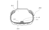
- the acceleration sensor 11 is disposed at a substantially central portion of the inner liner portion 21 of the tire 20 on the tire air chamber 22 side, and detects vibration input from the road surface to the tread 23 of the tire 20 as acceleration.
- the acceleration sensor 11 is arranged so that the detection direction is the tire circumferential direction, and the tire circumferential vibration input from the road surface is detected.
- the position of the acceleration sensor 11 (strictly speaking, the position of the surface of the tread 23 on the outer side in the radial direction of the acceleration sensor 11) is referred to as a measurement point.
- the output of the acceleration sensor 11 is sent to the vehicle control apparatus provided in the vehicle body side by the transmitter 11F, for example.
- the wheel speed sensor 12 detects the rotational speed of the wheel (hereinafter referred to as wheel speed).
- wheel speed For example, a rotor having a gear formed on the outer peripheral portion thereof and rotating together with the wheel, a yoke constituting the rotor and a magnetic circuit
- a known electromagnetic induction type wheel speed sensor that includes a coil that detects a change in magnetic flux of the magnetic circuit and detects a rotation angle of the wheel.
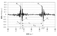
- the vibration waveform detection means 13 detects a time series waveform of vibration in which the vibrations input to the running tire 20 that is the output of the acceleration sensor 11 are arranged in time series. As shown in FIG. 3, in the time-series waveform of vibration, two large positive and negative peaks appear every time the tire rotates. First occurrence peak (here, positive peak) in the time-series waveform of the vibration, the peak of the measurement point is generated when striking the road surface, the peak is depression point P f. The next peak (in this case, a negative peak) is a peak that occurs when the measurement point leaves the road surface, and this peak is the kicking point P k .
- the tread kick position estimating means 14 detects two positive and negative peaks that appear first from the time series waveform of vibration, and the time at which these peaks appear is determined as the position t 11 of the stepping point P f , and It is estimated that the position t 12 of the kicking point P k and the times of the two positive and negative peaks that appear later are respectively the position t 21 of the next stepping point P f and the next kicking point P k . Estimated as position t 22 .
- Contact time and rotation time calculating means 15 the difference between the position t 12 position t 11 and trailing point P k of the depression point P f, a ground measurement point is the time in contact with the road surface time T a calculates a, from the difference between position t 22 position t 12 and trailing point P k of the kick-out point P k of the calculated rotation time T ab is the time at which the tire 20 rotates 1.
- T a t 12 ⁇ t 11
- T b t 21 ⁇ t 12
- T ab t 22 ⁇ t 12 .
- the rotation time T ab may be calculated from a difference between position t 21 position t 11 and the depression point P f of the depression point P f.
- the determination unit 16 includes a contact time ratio calculation unit 161, a comparison determination unit 162, and a stop signal output unit 163.
- the contact time ratio calculation unit 161 calculates a contact time ratio R, which is a ratio between the contact time T a calculated by the contact time / rotation time calculation means 15 and the rotation time T ab .
- the comparison determination unit 162 determines that the position t 11 of the stepping point P f estimated by the stepping kick position estimating unit 14 and the positions t 12 and t 22 of the kicking point P k are all the positions of the actual stepping point. It is determined whether or not it is the position of the kicking point.
- the grounding time ratio R is within a preset grounding time ratio range [R1, R2], and the grounding time ratio R is within the grounding time ratio range (R1 ⁇ R ⁇ R2).
- t 11 estimated by the position estimating portion 14 kicks stepping, t 12, t 22 determines that all the position of the actual position and kicking point depression point (normal position).
- the contact time ratio R is out of the contact time ratio range (R ⁇ R1 or R> R2), the estimated position t 11 of the depression point P f and the positions t 12 and t 22 of the kicking point P k.
- the determination by the comparison determination unit 162 is an erroneous estimation, that is, when the stop signal output unit 163 determines that the estimation of the position of the stepping point P f and the position of the kicking point P k has failed, the road surface state A stop signal, which is a command signal for stopping the road surface estimation operation, is output to the estimating means 18.
- the storage unit 17 stores a map 17M indicating the relationship between the road surface condition obtained in advance and the calculated value of the vibration level.
- the road surface state estimating unit 18 includes a waveform region dividing unit 181, a region signal extracting unit 182, a frequency analyzing unit 183, a vibration level calculating unit 184, and a road surface state estimating unit 185.
- the road surface state is estimated only when it is determined that the estimated stepping point position and kicking point position are the actual stepping point position and kicking point position, and a stop signal is output from the stop signal output unit 163. If it is output, the estimation of the road surface condition is stopped.
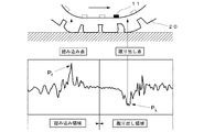
- the waveform area dividing unit 181 uses the position of the stepping point P f or the kicking point P k estimated by the stepping kick position estimating means 14 and the rotation speed of the tire 20 detected by the wheel speed sensor 12 to make one rotation of the tire. In addition to extracting the minute vibration waveform, the vibration waveform is divided into data of two regions, a stepping region and a kicking region as shown in FIG.
- the region signal extraction unit 182 extracts the time series waveform of the vibration level of each region.
- the frequency analysis unit 183 includes frequency analysis means such as an FFT analyzer, and creates a frequency spectrum obtained by frequency analysis of the extracted time series waveform of each vibration level.
- the vibration level calculation unit 184 includes a stepping vibration level V f that is a vibration level in a predetermined frequency band in the frequency spectrum of the stepping area, and a kicking vibration level V k that is a vibration level in the predetermined frequency band in the frequency spectrum of the kicking area. And a vibration level calculation value S is calculated using these vibration levels. Examples of the calculated value S include a ratio of the stepping vibration level V f to the kicking vibration level V k .
- the road surface state estimation unit 185 stores the map 17M indicating the relationship between the road surface state obtained in advance and the calculated vibration level S stored in the storage unit 17, and the vibration level calculated by the vibration level calculation unit 184. From the data of the calculated value S, the state of the road surface on which the vehicle is traveling is estimated.
- the tire circumferential direction vibration of the running tire 20 is detected by the acceleration sensor 11 (step S10), and the output is sent to the vibration waveform detecting means 13, and the tire circumferential direction vibration waveform arranged in time series.
- a time series waveform of vibration is obtained (step S11).
- the tread kick position estimating means 14 determines the position t 11 of the first appearing step point P f and the position of the first appearing kick point P k from the time series waveform of vibration as shown in FIG. t 12 and the position t 22 of the kicking point P k that appears later are estimated (step S 12).
- the contact time / rotation time calculation means 15 calculates the contact time T a and the rotation time T ab using t 11 , t 12 , t 22 detected in step S12 (step S13).
- the determination unit 16 after calculating the contact time ratio R is the ratio of the rotation time T ab and the contact time T a (step S14), and the contact time ratio ranges this contact time ratio R is set in advance It is determined whether or not it is within [R1, R2], and whether or not all of t 11 , t 12 , and t 22 detected in step S12 are the actual stepping point P f and kicking point P k.
- the tread kick position is determined (step S15).
- a large input when there is an excessive input (hereinafter referred to as a large input) to the tire 20 such as when overcoming a protrusion or curb, a large peak occurs in the time series waveform as shown in FIG.
- the positions of the stepping point P f and the kicking point P k are erroneously estimated. For example, as shown in the figure, when the position of the large input is estimated as the position of the subsequent kick point P k , the calculated rotation time t ab is shorter than the actual rotation time T ab. Become. Also, if you've estimated that depression point P f after the position of the large input is shorter than the actual contact time contact time t a is T a.
- the grounding time ratio range [R1, R2] is set with respect to the grounding time ratio R, R is compared with the lower limit value R1 of the grounding time ratio range and the upper limit value R2 of the grounding time ratio range, and the grounding time is compared. If it is determined whether the ratio R is in the contact time ratio range, the position t 11 of the stepping point P f estimated by the stepping kick position estimating means 14 and the positions t 12 and t 22 of the kick point P k are determined. It is possible to perform a step kick position determination for determining whether or not the position is an actual step position and a kick point position.
- step S15 If the result of step kick position determination is “normal position” in step S15, the process proceeds to step S16, and the road surface state is estimated using the time series waveform of the vibration level.
- step S17 if the result of the stepping kick position determination is “incorrect estimation”, a stop signal is output to the road surface condition estimating means 18 (step S17), and then the process returns to step S10 and the tire of the running tire 20 is returned.
- step S17 the stop signal is output, the estimation of the road surface condition is stopped.
- step S18 it is determined whether road surface state estimation operation was complete
- the road surface state estimation method in step S16 is as follows. First, a vibration waveform for one rotation of the tire is extracted from the time series waveform of the vibration input to the running tire 20 that is the output of the acceleration sensor 11, and the extracted vibration waveform is divided into a stepping area and a kicking area. After dividing into data of two regions, time series waveforms of vibration levels in each region are extracted. Next, after calculating the vibration levels V f and V k in a predetermined frequency band from the frequency spectrum of each region obtained by frequency analysis of the extracted time series waveform of each vibration level, the vibration level V f and A calculation value S of V k is calculated.
- the estimation and calculation value S the state of the road surface on which the vehicle runs and a map 17M vehicle showing the relationship between the calculated value S r of previously obtained road surface condition and the vibration level.
- the vibration level V f in the frequency band of 8 to 10 kHz is calculated from the frequency spectrum of the stepping area
- the vibration level V k in the frequency band of 1 to 3 kHz is calculated from the frequency spectrum of the kicking area.
- calculated value S V f / V k to investigate whether close to the calculated value S r of which road surface, to estimate the state of the road surface.
- the acceleration sensor 11 is arranged on the tire 20, the tire circumferential vibration of the running tire 20 is detected, and the peak position appearing in the time-varying waveform of the tire circumferential vibration. From this, the position of the tire depression point P f and the position of the kick point P k are estimated, and the contact time T of the tire 20 is determined from the estimated position of the depression point P f and the position of the kick point P k. a , a non-contact time T b , and a rotation time T ab are calculated or any one or more of the calculated contact time T a , non-contact time T b , and rotation time T ab are calculated.
- kick kicking Position determination result is incorrect
- kick kicking Position determination result is incorrect
- the estimation accuracy of the road surface condition can be improved.
- step S15 when the ground contact time or the ground contact length estimated from the ground contact time is outside a predetermined ground contact length range, one or both of the estimated stepping point position and kicking point position is You may make it determine with not the position of an actual depression point, and the position of a kick-out point.
- step S15 when the rotation time or the rotation length estimated from the rotation time is outside the rotation length range set in advance, one or both of the estimated stepping point position and the kicking point position are both May be determined not to be the actual stepping-on point position and kicking-out point position. Thereby, it is possible to determine whether or not the position of the stepping point and the position of the kicking point estimated by a simple method are the actual position of the stepping point and the position of the kicking point.
- step S15 a contact time ratio, which is a ratio between the contact time and the rotation time, is calculated, and when the calculated contact time ratio is outside a preset contact time ratio range, the estimated depression point is calculated. It may be determined that one or both of the position and the kicking point position are not the actual stepping point position and the kicking point position. As a result, it is possible to determine whether the estimated depression point position and kicking point position are the actual depression point position and kicking point position regardless of the wheel speed. The estimation accuracy can be further improved.
- FIG. 7 is a diagram comparing the result of erroneous estimation in the tread kick position determination according to the present invention and the result of large input detection by the monitoring acceleration sensor described in Patent Document 1, which is apparent from FIG.
- the tread kick position determination according to the present invention has a determination accuracy equal to or higher than the large input detection described in Patent Document 1.
- the acceleration sensor 11 is installed on the tire air chamber 22 side of the inner liner portion 21 of the tire 20 to detect the tire circumferential acceleration.
- the acceleration sensor is attached to the knuckle to accelerate the tire longitudinal acceleration. It is good also as a structure which detects.
- the tire circumferential direction acceleration detected by the acceleration sensor 11 is used to estimate the position of the stepping point P f , the position of the kicking point P k , and the road surface condition.
- tire radial acceleration may be used.
- the present invention is not limited thereto, for example, disclosed in Patent Document 1
- the present invention is applicable to any apparatus that estimates a road surface state using a time-varying waveform of tire vibration during traveling detected by vibration detection means.
- the output of the wheel speed sensor 12 is used to separate the vibration waveform into the kick-out region and the stepping-in region, but the time-series waveform of the vibration waveform is determined from the tire moving radius and the rotation time.
- the wheel speed sensor 12 can be omitted if it is converted into a vibration waveform at a predetermined position and separated into a kick-out area and a depression area. Therefore, the present invention can also be applied to a road surface state estimation device that does not include the wheel speed sensor 12 as a component.
- the tread kick position determination is performed based on the contact time ratio R.
- the tick kick position determination may be performed using any one of the contact time, the non-contact time, and the rotation time.
- the contact length and the rotation length are used instead of the contact time and the rotation time, so that the influence of the wheel speed can be eliminated, so that the accuracy of the stepping kick position determination is further improved. For example, in the case of using the grounding time or the grounding length, it is determined that the estimation is incorrect when the grounding time or the grounding length is out of a preset grounding length range. Further, when the rotation time or the rotation length is used, it is determined that there is an erroneous estimation when the rotation time or the rotation length is outside the preset rotation length range.
- one or both of the position of the stepping point and the position of the kicking point estimated from the contact time Ta and the rotation time Tab is the actual position of the stepping point and the position of the kicking point. It was determined whether the ground outside time T b is, since the difference between the rotation time T ab and contact time T a, the contact time T a and the ground outside the time T b, or ground out time T b Needless to say, it is possible to determine from the rotation time T ab whether one or both of the estimated depression point position and kicking point position are the actual depression point position and the kicking point position. Absent.
Landscapes
- Engineering & Computer Science (AREA)
- Mechanical Engineering (AREA)
- Physics & Mathematics (AREA)
- Transportation (AREA)
- Analytical Chemistry (AREA)
- Health & Medical Sciences (AREA)
- Life Sciences & Earth Sciences (AREA)
- Chemical & Material Sciences (AREA)
- Acoustics & Sound (AREA)
- Biochemistry (AREA)
- General Health & Medical Sciences (AREA)
- General Physics & Mathematics (AREA)
- Immunology (AREA)
- Pathology (AREA)
- Control Of Driving Devices And Active Controlling Of Vehicle (AREA)
- Tires In General (AREA)
- Length Measuring Devices With Unspecified Measuring Means (AREA)
Abstract
センサーの数を増やすことなく、タイヤに大入力があったか否かを精度よく判定して路面状態を推定する方法を提供するために、タイヤに加速度センサーを配置して、走行中のタイヤの振動を検出し、振動の時間変化波形に出現するピーク位置から、タイヤの踏み込み点の位置と蹴り出し点の位置とを推定するとともに、推定された踏み込み点の位置と蹴り出し点の位置とから算出されたタイヤの接地時間、接地外時間、及び、回転時間のいずれかまたは複数を用いて、推定された踏み込み点の位置と蹴り出し点の位置が実際の踏み込み点の位置と蹴り出し点の位置であるか否かを判定する踏み蹴り位置判定を行い、踏み蹴り位置判定の判定結果が誤推定である場合には、路面状態の推定を行わないようにした。
Description
本発明は、走行中の路面状態を推定する方法に関するものである。
自動車の走行安定性を高めるため、走行中の路面の状態を精度良く推定し、車両制御へフィードバックすることが求められている。予め路面状態を推定することができれば、制駆動や操舵といった危険回避の操作を起こす前に、例えば、ABSブレーキのより高度な制御等が可能になり、安全性が一段と高まることが予想される。
路面状態を推定する方法としては、タイヤのインナーライナー部に設置された加速度センサーで検出した走行中のタイヤトレッドの振動の時系列波形から、踏み込み点を含む領域の時系列波形と蹴り出し点を含む領域の時系列波形とを抽出して周波数分析し、得られた周波数スペクトルから、複数の周波数帯域の振動レベルである踏み込み領域の帯域値Pfiと蹴り出し領域の帯域値Pkjとをそれぞれ算出し、これらの帯域値Pfi,Pkjから路面状態を推定する方法が提案されている(例えば、特許文献1参照)。
路面状態を推定する方法としては、タイヤのインナーライナー部に設置された加速度センサーで検出した走行中のタイヤトレッドの振動の時系列波形から、踏み込み点を含む領域の時系列波形と蹴り出し点を含む領域の時系列波形とを抽出して周波数分析し、得られた周波数スペクトルから、複数の周波数帯域の振動レベルである踏み込み領域の帯域値Pfiと蹴り出し領域の帯域値Pkjとをそれぞれ算出し、これらの帯域値Pfi,Pkjから路面状態を推定する方法が提案されている(例えば、特許文献1参照)。
ところで、タイヤの踏み込み点及び蹴り出し点の位置は、振動の時系列波形に現れるピークの位置から特定されるが、タイヤに、突起や縁石を乗り越えたときのような過度な入力があった場合には、時系列波形上に大きなピークが発生するため、踏み込み点及び蹴り出し点の位置を誤推定してしまう場合がある。
そこで、前記特許文献1では、サスペンション部に監視用の加速度センサーを設置し、監視用の加速度センサーで検出した加速度の値が予め設定した閾値を超えた場合には、タイヤに過度な入力(以下、大入力という)があったと判定し、路面状態の推定を中止するようにしている。
そこで、前記特許文献1では、サスペンション部に監視用の加速度センサーを設置し、監視用の加速度センサーで検出した加速度の値が予め設定した閾値を超えた場合には、タイヤに過度な入力(以下、大入力という)があったと判定し、路面状態の推定を中止するようにしている。
しかしながら、前記特許文献1の方法では、サスペンション部に大入力を検出するための監視用の加速度センサーを設置する必要があった。
本発明は、従来の問題点に鑑みてなされたもので、センサーの数を増やすことなく、タイヤに大入力があったか否かを精度よく判定して路面状態を推定する方法を提供する。
本発明は、振動検出手段により検出した走行中のタイヤの振動の時間変化波形から、当該タイヤが走行している路面の状態を推定する路面状態推定方法であって、前記時間変化波形に出現するピーク位置から、前記タイヤの踏み込み点の位置と蹴り出し点の位置とを推定する踏み蹴り位置推定ステップと、前記推定された踏み込み点の位置と蹴り出し点の位置とから、当該タイヤの接地時間、接地外時間、及び、当該タイヤが1回転する時間である回転時間のいずれかまたは複数を算出する算出ステップと、前記算出された接地時間、接地外時間、及び、回転時間のいずれかまたは複数から、前記推定された踏み込み点の位置と蹴り出し点の位置が実際の踏み込み点の位置と蹴り出し点の位置であるか否かを判定する判定ステップとを備え、前記判定ステップで前記推定された踏み込み点の位置と蹴り出し点の位置の一方もしくは両方が実際の踏み込み点の位置と蹴り出し点の位置でないと判定された場合には、路面状態の推定を行わないようにしたことを特徴とする。
ここで、踏み込み点は、タイヤの振動の時間変化波形の、振動検出手段が設置されたタイヤ周上の位置(以下、計測点という)が路面に衝突する時刻もしくはタイヤ周上の位置を指し、蹴り出し点は、計測点が路面から離れる時刻もしくはタイヤ周上の位置を指す。
これにより、タイヤに大入力があった場合にタイヤの振動の時間変化波形に出現する大きなピークを踏み込み点のピークもしくは蹴り出し点のピークと誤推定することを避けることができるので、路面状態を精度よく推定することができる。
ここで、踏み込み点は、タイヤの振動の時間変化波形の、振動検出手段が設置されたタイヤ周上の位置(以下、計測点という)が路面に衝突する時刻もしくはタイヤ周上の位置を指し、蹴り出し点は、計測点が路面から離れる時刻もしくはタイヤ周上の位置を指す。
これにより、タイヤに大入力があった場合にタイヤの振動の時間変化波形に出現する大きなピークを踏み込み点のピークもしくは蹴り出し点のピークと誤推定することを避けることができるので、路面状態を精度よく推定することができる。
なお、前記発明の概要は、本発明の必要な全ての特徴を列挙したものではなく、これらの特徴群のサブコンビネーションもまた、発明となり得る。
図1は、本実施の形態に係る路面状態推定装置10の機能ブロック図である。
路面状態推定装置10は、振動検出手段としての加速度センサー11と、車輪速検出手段としての車輪速センサー12と、振動波形検出手段13と、踏み蹴り位置推定手段14と、接地時間・回転時間算出手段15と、判定手段16と、記憶手段17と、路面状態推定手段18とを備える。
振動波形検出手段13~判定手段16及び路面状態推定手段18の各手段は、例えば、コンピュータのソフトウェアにより構成され、記憶手段17は、RAM、ROMから構成され、車体側に設けられた車両制御装置に組み込まれる。
加速度センサー11は、図2に示すように、タイヤ20のインナーライナー部21のタイヤ気室22側のほぼ中央部に配置されて、路面から当該タイヤ20のトレッド23に入力する振動を加速度として検出する。本例では、加速度センサー11の検出方向をタイヤ周方向になるように配置して、路面から入力するタイヤ周方向振動を検出する。以下、加速度センサー11の位置(厳密には、加速度センサー11の径方向外側にあるトレッド23表面の位置)を計測点という。なお、加速度センサー11の出力は、例えば、送信機11Fにより、車体側に設けられた車両制御装置に送られる。
車輪速センサー12は、車輪の回転速度(以下、車輪速という)を検出するもので、例えば、外周部に歯車が形成され車輪とともに回転するローターと、このローターと磁気回路を構成するヨークと、磁気回路の磁束変化を検出するコイルとを備え、車輪の回転角度を検出する周知の電磁誘導型の車輪速センサーなどを用いることができる。
路面状態推定装置10は、振動検出手段としての加速度センサー11と、車輪速検出手段としての車輪速センサー12と、振動波形検出手段13と、踏み蹴り位置推定手段14と、接地時間・回転時間算出手段15と、判定手段16と、記憶手段17と、路面状態推定手段18とを備える。
振動波形検出手段13~判定手段16及び路面状態推定手段18の各手段は、例えば、コンピュータのソフトウェアにより構成され、記憶手段17は、RAM、ROMから構成され、車体側に設けられた車両制御装置に組み込まれる。
加速度センサー11は、図2に示すように、タイヤ20のインナーライナー部21のタイヤ気室22側のほぼ中央部に配置されて、路面から当該タイヤ20のトレッド23に入力する振動を加速度として検出する。本例では、加速度センサー11の検出方向をタイヤ周方向になるように配置して、路面から入力するタイヤ周方向振動を検出する。以下、加速度センサー11の位置(厳密には、加速度センサー11の径方向外側にあるトレッド23表面の位置)を計測点という。なお、加速度センサー11の出力は、例えば、送信機11Fにより、車体側に設けられた車両制御装置に送られる。
車輪速センサー12は、車輪の回転速度(以下、車輪速という)を検出するもので、例えば、外周部に歯車が形成され車輪とともに回転するローターと、このローターと磁気回路を構成するヨークと、磁気回路の磁束変化を検出するコイルとを備え、車輪の回転角度を検出する周知の電磁誘導型の車輪速センサーなどを用いることができる。
振動波形検出手段13は、加速度センサー11の出力である走行中のタイヤ20に入力する振動を時系列に配列した振動の時系列波形を検出する。
図3に示すように、振動の時系列波形には、タイヤ1回転毎に正・負2つの大きなピークが出現する。
振動の時系列波形において最初に出現するピーク(ここでは、正のピーク)は、計測点が路面に衝突するときに発生するピークで、このピークが踏み込み点Pfである。次に出現するピーク(ここでは、負のピーク)は、計測点が路面を離れるときに発生するピークで、このピークが蹴り出し点Pkである。
踏み蹴り位置推定手段14は、振動の時系列波形から、先に出現する正・負2つのピークを検出し、これらピークの出現する時刻を、それぞれ、踏み込み点Pfの位置t11、及び、蹴り出し点Pkの位置t12と推定するとともに、後に出現する正・負2つのピークの時刻を、それぞれ、次の踏み込み点Pfの位置t21、及び、次の蹴り出し点Pkの位置t22と推定する。
接地時間・回転時間算出手段15は、前記の踏み込み点Pfの位置t11と蹴り出し点Pkの位置t12との差から、計測点が路面と接している時間である接地時間Taを算出するとともに、前記の蹴り出し点Pkの位置t12と蹴り出し点Pkの位置t22との差から、タイヤ20が1回転する時間である回転時間Tabを算出する。なお、前記の蹴り出し点Pkの位置t12と踏み込み点Pfの位置t21との差か接地外時間Tbである。
Ta=t12-t11、Tb=t21-t12、Tab=t22-t12である。
また、回転時間Tabを、前記の踏み込み点Pfの位置t11と踏み込み点Pfの位置t21との差から算出してもよい。
図3に示すように、振動の時系列波形には、タイヤ1回転毎に正・負2つの大きなピークが出現する。
振動の時系列波形において最初に出現するピーク(ここでは、正のピーク)は、計測点が路面に衝突するときに発生するピークで、このピークが踏み込み点Pfである。次に出現するピーク(ここでは、負のピーク)は、計測点が路面を離れるときに発生するピークで、このピークが蹴り出し点Pkである。
踏み蹴り位置推定手段14は、振動の時系列波形から、先に出現する正・負2つのピークを検出し、これらピークの出現する時刻を、それぞれ、踏み込み点Pfの位置t11、及び、蹴り出し点Pkの位置t12と推定するとともに、後に出現する正・負2つのピークの時刻を、それぞれ、次の踏み込み点Pfの位置t21、及び、次の蹴り出し点Pkの位置t22と推定する。
接地時間・回転時間算出手段15は、前記の踏み込み点Pfの位置t11と蹴り出し点Pkの位置t12との差から、計測点が路面と接している時間である接地時間Taを算出するとともに、前記の蹴り出し点Pkの位置t12と蹴り出し点Pkの位置t22との差から、タイヤ20が1回転する時間である回転時間Tabを算出する。なお、前記の蹴り出し点Pkの位置t12と踏み込み点Pfの位置t21との差か接地外時間Tbである。
Ta=t12-t11、Tb=t21-t12、Tab=t22-t12である。
また、回転時間Tabを、前記の踏み込み点Pfの位置t11と踏み込み点Pfの位置t21との差から算出してもよい。
判定手段16は、接地時間比算出部161と、比較判定部162と、中止信号出力部163とを備える。
接地時間比算出部161は、接地時間・回転時間算出手段15で算出した接地時間Taと回転時間Tabとの比である接地時間比Rを算出する。
比較判定部162は、踏み蹴り位置推定手段14で推定した踏み込み点Pfの位置t11と、蹴り出し点Pkの位置t12,t22の位置が、全て、実際の踏み込み点の位置と蹴り出し点の位置であるか否かを判定する。
具体的には、接地時間比Rが予め設定された接地時間比範囲[R1,R2]内にあるか否かを判定し、接地時間比Rが接地時間比範囲内(R1≦R≦R2)にある場合には、踏み蹴り位置推定手段14で推定されたt11,t12,t22が全て実際の踏み込み点の位置と蹴り出し点の位置(正常位置)であると判定する。
一方、接地時間比Rが接地時間比範囲外(R<R1またはR>R2)のときには、推定された踏み込み点Pfの位置t11と蹴り出し点Pkの位置t12,t22の位置うちの、いずれか一つ、もしくは、2つ、もしくは全部が実際の踏み込み点の位置と蹴り出し点の位置ではない(誤推定)と判定する。
中止信号出力部163は、比較判定部162の判定が誤推定である場合、すなわち、踏み込み点Pfの位置と蹴り出し点Pkの位置の推定に失敗したと判定した場合には、路面状態推定手段18に路面推定操作を中止するための指令信号である中止信号を出力する。
接地時間比算出部161は、接地時間・回転時間算出手段15で算出した接地時間Taと回転時間Tabとの比である接地時間比Rを算出する。
比較判定部162は、踏み蹴り位置推定手段14で推定した踏み込み点Pfの位置t11と、蹴り出し点Pkの位置t12,t22の位置が、全て、実際の踏み込み点の位置と蹴り出し点の位置であるか否かを判定する。
具体的には、接地時間比Rが予め設定された接地時間比範囲[R1,R2]内にあるか否かを判定し、接地時間比Rが接地時間比範囲内(R1≦R≦R2)にある場合には、踏み蹴り位置推定手段14で推定されたt11,t12,t22が全て実際の踏み込み点の位置と蹴り出し点の位置(正常位置)であると判定する。
一方、接地時間比Rが接地時間比範囲外(R<R1またはR>R2)のときには、推定された踏み込み点Pfの位置t11と蹴り出し点Pkの位置t12,t22の位置うちの、いずれか一つ、もしくは、2つ、もしくは全部が実際の踏み込み点の位置と蹴り出し点の位置ではない(誤推定)と判定する。
中止信号出力部163は、比較判定部162の判定が誤推定である場合、すなわち、踏み込み点Pfの位置と蹴り出し点Pkの位置の推定に失敗したと判定した場合には、路面状態推定手段18に路面推定操作を中止するための指令信号である中止信号を出力する。
記憶手段17は、予め求めておいた路面状態と振動レベルの演算値との関係を示すマップ17Mを記憶する。
路面状態推定手段18は、波形領域分割部181と、領域信号抽出部182と、周波数分析部183と、振動レベル算出部184と、路面状態推定部185とを備え、踏み蹴り位置推定手段14で推定された踏み込み点の位置と蹴り出し点の位置が実際の踏み込み点の位置と蹴り出し点の位置であると判定された場合のみ路面状態の推定を行い、中止信号出力部163から中止信号が出力された場合には、路面状態の推定を中止する。
波形領域分割部181は、踏み蹴り位置推定手段14で推定した踏み込み点Pfもしくは蹴り出し点Pkの位置と、車輪速センサー12で検出したタイヤ20の回転速度とを用いて、タイヤ一回転分の振動波形を抽出するとともに、この振動波形を、図4に示すような踏み込み領域と蹴り出し領域との2つの領域のデータに分割する。
領域信号抽出部182は、各領域の振動レベルの時系列波形をそれぞれ抽出する。
周波数分析部183は、FFTアナライザーなどの周波数分析手段から構成され、抽出された各振動レベルの時系列波形を周波数分析した周波数スペクトルを作成する。
振動レベル算出部184は、踏み込み領域の周波数スペクトルにおける所定周波数帯域における振動レベルである踏み込み振動レベルVfと、蹴り出し領域の周波数スペクトルにおける所定周波数帯域における振動レベルである蹴り出し振動レベルVkとを算出するとともに、これらの振動レベルを用いて振動レベルの演算値Sを算出する。演算値Sとしては、蹴り出し振動レベルVkに対する踏み込み振動レベルVfの比などを挙げることができる。
路面状態推定部185は、記憶手段17に記憶されている、予め求めておいた路面状態と振動レベルの演算値Sとの関係を示すマップ17Mと、振動レベル算出部184で算出された振動レベルの演算値Sのデータとから、車両の走行している路面の状態を推定する。
路面状態推定手段18は、波形領域分割部181と、領域信号抽出部182と、周波数分析部183と、振動レベル算出部184と、路面状態推定部185とを備え、踏み蹴り位置推定手段14で推定された踏み込み点の位置と蹴り出し点の位置が実際の踏み込み点の位置と蹴り出し点の位置であると判定された場合のみ路面状態の推定を行い、中止信号出力部163から中止信号が出力された場合には、路面状態の推定を中止する。
波形領域分割部181は、踏み蹴り位置推定手段14で推定した踏み込み点Pfもしくは蹴り出し点Pkの位置と、車輪速センサー12で検出したタイヤ20の回転速度とを用いて、タイヤ一回転分の振動波形を抽出するとともに、この振動波形を、図4に示すような踏み込み領域と蹴り出し領域との2つの領域のデータに分割する。
領域信号抽出部182は、各領域の振動レベルの時系列波形をそれぞれ抽出する。
周波数分析部183は、FFTアナライザーなどの周波数分析手段から構成され、抽出された各振動レベルの時系列波形を周波数分析した周波数スペクトルを作成する。
振動レベル算出部184は、踏み込み領域の周波数スペクトルにおける所定周波数帯域における振動レベルである踏み込み振動レベルVfと、蹴り出し領域の周波数スペクトルにおける所定周波数帯域における振動レベルである蹴り出し振動レベルVkとを算出するとともに、これらの振動レベルを用いて振動レベルの演算値Sを算出する。演算値Sとしては、蹴り出し振動レベルVkに対する踏み込み振動レベルVfの比などを挙げることができる。
路面状態推定部185は、記憶手段17に記憶されている、予め求めておいた路面状態と振動レベルの演算値Sとの関係を示すマップ17Mと、振動レベル算出部184で算出された振動レベルの演算値Sのデータとから、車両の走行している路面の状態を推定する。
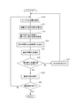
次に、本実施の形態に係る路面状態の推定方法について、図5のフローチャートを参照して説明する。
まず、加速度センサー11にて走行中のタイヤ20のタイヤ周方向振動を検出し(ステップS10)、その出力を振動波形検出手段13に送って、時系列に配列したタイヤ周方向の振動波形である振動の時系列波形を求める(ステップS11)。
次に、踏み蹴り位置推定手段14にて、図3に示すような振動の時系列波形から、先に出現する踏み込み点Pfの位置t11と、先に出現する蹴り出し点Pkの位置t12と、後に出現する蹴り出し点Pkの位置t22と推定する(ステップS12)。
そして、接地時間・回転時間算出手段15にて、ステップS12で検出したt11,t12,t22とを用いて、接地時間Taと回転時間Tabを算出する(ステップS13)。
次に、判定手段16にて、接地時間Taと回転時間Tabとの比である接地時間比Rを算出(ステップS14)した後、この接地時間比Rが予め設定された接地時間比範囲[R1,R2]内にあるか否かを判定し、ステップS12で検出したt11,t12,t22の全てが、実際の踏み込み点Pf及び蹴り出し点Pkの位置であるか否かを判定する踏み蹴り位置判定を行う(ステップS15)。
まず、加速度センサー11にて走行中のタイヤ20のタイヤ周方向振動を検出し(ステップS10)、その出力を振動波形検出手段13に送って、時系列に配列したタイヤ周方向の振動波形である振動の時系列波形を求める(ステップS11)。
次に、踏み蹴り位置推定手段14にて、図3に示すような振動の時系列波形から、先に出現する踏み込み点Pfの位置t11と、先に出現する蹴り出し点Pkの位置t12と、後に出現する蹴り出し点Pkの位置t22と推定する(ステップS12)。
そして、接地時間・回転時間算出手段15にて、ステップS12で検出したt11,t12,t22とを用いて、接地時間Taと回転時間Tabを算出する(ステップS13)。
次に、判定手段16にて、接地時間Taと回転時間Tabとの比である接地時間比Rを算出(ステップS14)した後、この接地時間比Rが予め設定された接地時間比範囲[R1,R2]内にあるか否かを判定し、ステップS12で検出したt11,t12,t22の全てが、実際の踏み込み点Pf及び蹴り出し点Pkの位置であるか否かを判定する踏み蹴り位置判定を行う(ステップS15)。
ところで、突起や縁石を乗り越えたときのように、タイヤ20に過度な入力(以下、大入力という)があった場合には、図6に示すように、時系列波形に大きなピークが発生するため、踏み込み点Pf及び蹴り出し点Pkの位置を誤推定してしまう場合がある。
例えば、同図に示すように、大入力の位置を後の蹴り出し点Pkの位置と推定してしまった場合には、算出された回転時間tabが実際の回転時間Tabよりも短くなる。
また、大入力の位置を後の踏み込み点Pfと推定してしまった場合には、接地時間taが実際の接地時間Taよりも短くなる。
そこで、接地時間比Rに対して接地時間比範囲[R1,R2]を設定して、Rと、接地時間比範囲の下限値R1及び接地時間比範囲の上限値R2とを比較し、接地時間比Rが接地時間比範囲にあるか否かを判定すれば、踏み蹴り位置推定手段14で推定された踏み込み点Pfの位置t11と、蹴り出し点Pkの位置t12,t22の位置が、実際の踏み込み点の位置と蹴り出し点の位置であるか否かを判定する踏み蹴り位置判定を行うことができる。
ステップS15において、踏み蹴り位置判定の結果が「正常位置」だった場合には、ステップS16に進み、振動レベルの時系列波形を用いて路面状態の推定を行う。
一方、踏み蹴り位置判定の結果が「誤推定」だった場合には、路面状態推定手段18に中止信号を出力(ステップS17)してから、ステップS10に戻って、走行中のタイヤ20のタイヤ周方向振動の検出を継続する。
中止信号が出力されたときには、路面状態の推定を中止する。
なお、ステップS16が終了した場合には、路面状態の推定操作が終了したか否かを判定し(ステップS18)、推定操作を継続する場合には、ステップS10に戻って、走行中のタイヤ20のタイヤ周方向振動の検出を継続し、継続しない場合には本操作を終了する。
例えば、同図に示すように、大入力の位置を後の蹴り出し点Pkの位置と推定してしまった場合には、算出された回転時間tabが実際の回転時間Tabよりも短くなる。
また、大入力の位置を後の踏み込み点Pfと推定してしまった場合には、接地時間taが実際の接地時間Taよりも短くなる。
そこで、接地時間比Rに対して接地時間比範囲[R1,R2]を設定して、Rと、接地時間比範囲の下限値R1及び接地時間比範囲の上限値R2とを比較し、接地時間比Rが接地時間比範囲にあるか否かを判定すれば、踏み蹴り位置推定手段14で推定された踏み込み点Pfの位置t11と、蹴り出し点Pkの位置t12,t22の位置が、実際の踏み込み点の位置と蹴り出し点の位置であるか否かを判定する踏み蹴り位置判定を行うことができる。
ステップS15において、踏み蹴り位置判定の結果が「正常位置」だった場合には、ステップS16に進み、振動レベルの時系列波形を用いて路面状態の推定を行う。
一方、踏み蹴り位置判定の結果が「誤推定」だった場合には、路面状態推定手段18に中止信号を出力(ステップS17)してから、ステップS10に戻って、走行中のタイヤ20のタイヤ周方向振動の検出を継続する。
中止信号が出力されたときには、路面状態の推定を中止する。
なお、ステップS16が終了した場合には、路面状態の推定操作が終了したか否かを判定し(ステップS18)、推定操作を継続する場合には、ステップS10に戻って、走行中のタイヤ20のタイヤ周方向振動の検出を継続し、継続しない場合には本操作を終了する。
ステップS16における路面状態の推定方法は、以下の通りである。
まず、加速度センサー11の出力である走行中のタイヤ20に入力する振動の時系列波形から、タイヤ一回転分の振動波形を抽出し、抽出された振動波形を、踏み込み領域と蹴り出し領域との2つの領域のデータに分割した後、各領域の振動レベルの時系列波形をそれぞれ抽出する。
次に、抽出された各振動レベルの時系列波形をそれぞれ周波数分析して得られた各領域の周波数スペクトルから、所定周波数帯域における振動レベルVf及びVkを算出した後、振動レベルVf及びVkの演算値Sを算出する。
そして、演算値Sと、予め求めておいた路面状態と振動レベルの演算値Srとの関係を示すマップ17Mとから車両の走行している路面の状態を推定する。
具体的には、踏み込み領域の周波数スペクトルから、8~10kHzの周波数帯域での振動レベルVfを算出し、蹴り出し領域の周波数スペクトルから、1~3kHzの周波数帯域での振動レベルVkをし、演算値S=Vf/Vkがどの路面の演算値Srに近いかを調べることで、路面の状態を推定する。
まず、加速度センサー11の出力である走行中のタイヤ20に入力する振動の時系列波形から、タイヤ一回転分の振動波形を抽出し、抽出された振動波形を、踏み込み領域と蹴り出し領域との2つの領域のデータに分割した後、各領域の振動レベルの時系列波形をそれぞれ抽出する。
次に、抽出された各振動レベルの時系列波形をそれぞれ周波数分析して得られた各領域の周波数スペクトルから、所定周波数帯域における振動レベルVf及びVkを算出した後、振動レベルVf及びVkの演算値Sを算出する。
そして、演算値Sと、予め求めておいた路面状態と振動レベルの演算値Srとの関係を示すマップ17Mとから車両の走行している路面の状態を推定する。
具体的には、踏み込み領域の周波数スペクトルから、8~10kHzの周波数帯域での振動レベルVfを算出し、蹴り出し領域の周波数スペクトルから、1~3kHzの周波数帯域での振動レベルVkをし、演算値S=Vf/Vkがどの路面の演算値Srに近いかを調べることで、路面の状態を推定する。
このように、本実施の形態によれば、タイヤ20に加速度センサー11を配置して、走行中のタイヤ20のタイヤ周方向振動を検出し、タイヤ周方向振動の時間変化波形に出現するピーク位置から、タイヤの踏み込み点Pfの位置と蹴り出し点Pkの位置とを推定するとともに、推定された踏み込み点Pfの位置と蹴り出し点Pkの位置とから、タイヤ20の接地時間Ta、接地外時間Tb、及び、回転時間Tabのいずれかまたは複数を算出し、この算出された接地時間Ta、接地外時間Tb、及び、回転時間Tabのいずれかまたは複数を用いて、推定された踏み込み点Pfの位置と蹴り出し点の位置Pkが実際の踏み込み点の位置と蹴り出し点の位置であるか否かを判定する踏み蹴り位置判定を行い、踏み蹴り位置判定の判定結果が誤推定である場合には、路面状態の推定を行わないようにしたので、センサーの数を増やすことなく、タイヤに過度な入力があったか否かを精度よく判定することができる。したがって、路面状態の推定精度を向上させることができる。
なお、ステップS15において、接地時間もしくは接地時間から推定される接地長が、予め設定された接地長範囲外であるときに、推定された踏み込み点の位置と蹴り出し点の位置の一方もしくは両方が実際の踏み込み点の位置と蹴り出し点の位置ではないと判定するようにしてもよい。
また、ステップS15において、回転時間もしくは回転時間から推定される回転長さが、予め設定された回転長範囲外であるときに、推定された踏み込み点の位置と蹴り出し点の位置の一方もしくは両方が実際の踏み込み点の位置と蹴り出し点の位置ではないと判定するようにしてもよい。
これにより、簡単な方法で推定された踏み込み点の位置と蹴り出し点の位置が実際の踏み込み点の位置と蹴り出し点の位置であるか否かを判定することができる。
また、ステップS15において、回転時間もしくは回転時間から推定される回転長さが、予め設定された回転長範囲外であるときに、推定された踏み込み点の位置と蹴り出し点の位置の一方もしくは両方が実際の踏み込み点の位置と蹴り出し点の位置ではないと判定するようにしてもよい。
これにより、簡単な方法で推定された踏み込み点の位置と蹴り出し点の位置が実際の踏み込み点の位置と蹴り出し点の位置であるか否かを判定することができる。
また、ステップS15において、接地時間と回転時間との比である接地時間比を算出し、前記算出された接地時間比が予め設定された接地時間比範囲外であるときに、推定された踏み込み点の位置と蹴り出し点の位置の一方もしくは両方が実際の踏み込み点の位置と蹴り出し点の位置ではないと判定するようにしてもよい。
これにより、車輪速によらず、推定された踏み込み点の位置と蹴り出し点の位置が実際の踏み込み点の位置と蹴り出し点の位置であるか否かを判定することができるので、路面状態の推定精度を更に向上させることができる。
これにより、車輪速によらず、推定された踏み込み点の位置と蹴り出し点の位置が実際の踏み込み点の位置と蹴り出し点の位置であるか否かを判定することができるので、路面状態の推定精度を更に向上させることができる。
[実験例]
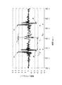
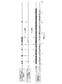
図7は、本発明による踏み蹴り位置判定における誤推定の結果と、前記特許文献1に記載の監視用の加速度センサーによる大入力検出の結果とを比較した図で、同図からも明らかなように、本発明による踏み蹴り位置判定は、前記特許文献1に記載の大入力検出と同等以上の判定精度を有していることが分かる。
これにより、大入力があった場合でも、振動波形から推定された踏み込み点の位置と蹴り出し点の位置が実際の踏み込み点の位置と蹴り出し点の位置であるか否かを精度よく判定できることが確認された。
図7は、本発明による踏み蹴り位置判定における誤推定の結果と、前記特許文献1に記載の監視用の加速度センサーによる大入力検出の結果とを比較した図で、同図からも明らかなように、本発明による踏み蹴り位置判定は、前記特許文献1に記載の大入力検出と同等以上の判定精度を有していることが分かる。
これにより、大入力があった場合でも、振動波形から推定された踏み込み点の位置と蹴り出し点の位置が実際の踏み込み点の位置と蹴り出し点の位置であるか否かを精度よく判定できることが確認された。
以上、本発明を実施の形態及び実験例を用いて説明したが、本発明の技術的範囲は前記実施の形態に記載の範囲には限定されない。前記実施の形態に、多様な変更または改良を加えることが可能であることが当業者にも明らかである。そのような変更または改良を加えた形態も本発明の技術的範囲に含まれ得ることが、特許請求の範囲から明らかである。
例えば、前記実施の形態では、タイヤ20のインナーライナー部21のタイヤ気室22側に加速度センサー11を設置してタイヤ周方向加速度を検出したが、ナックルに加速度センサーを取付けてタイヤ前後方向の加速度を検出する構成としてもよい。
また、前記実施の形態では、加速度センサー11で検出したタイヤ周方向加速度を用いて、踏み込み点Pfの位置、蹴り出し点Pkの位置、及び、路面状態を推定したが、タイヤ幅方向加速度、もしくは、タイヤ径方向加速度を用いてもよい。但し、タイヤ径方向加速度を用いる場合には、検出したタイヤ径方向加速度を微分した微分加速度を用いる方が、踏み込み点Pfの位置及び蹴り出し点Pkの位置をより正確に推定できるので、好ましい。
また、前記実施の形態では、加速度センサー11で検出したタイヤ周方向加速度を用いて、踏み込み点Pfの位置、蹴り出し点Pkの位置、及び、路面状態を推定したが、タイヤ幅方向加速度、もしくは、タイヤ径方向加速度を用いてもよい。但し、タイヤ径方向加速度を用いる場合には、検出したタイヤ径方向加速度を微分した微分加速度を用いる方が、踏み込み点Pfの位置及び蹴り出し点Pkの位置をより正確に推定できるので、好ましい。
また、前記実施の形態では、加速度センサー11で検出されたタイヤの振動の時系列波形から求めた踏み込み振動レベルVfと蹴り出し振動レベルVkの演算値Sと、予め求めておいた路面状態と振動レベルの演算値Srとの関係を示すマップ17Mとから車両の走行している路面の状態を推定したが、本発明はこれに限るものではなく、例えば、前記特許文献1に開示されているような、振動検出手段により検出した走行中のタイヤの振動の時間変化波形を用いて路面状態を推定する装置であれば適応可能である。
また、前記実施の形態では、車輪速センサー12の出力を用いて、振動波形を蹴り出し領域と踏み込み領域とに分離したが、タイヤの動半径と回転時間とから振動波形の時系列波形をタイヤの所定の位置の振動波形に変換して蹴り出し領域と踏み込み領域とに分離するようにすれば、車輪速センサー12を省略することができる。
したがって、本願発明は、車輪速センサー12を構成要素としない路面状態推定装置にも適用可能である。
また、前記実施の形態では、車輪速センサー12の出力を用いて、振動波形を蹴り出し領域と踏み込み領域とに分離したが、タイヤの動半径と回転時間とから振動波形の時系列波形をタイヤの所定の位置の振動波形に変換して蹴り出し領域と踏み込み領域とに分離するようにすれば、車輪速センサー12を省略することができる。
したがって、本願発明は、車輪速センサー12を構成要素としない路面状態推定装置にも適用可能である。
また、前記実施の形態では、接地時間比Rにより踏み蹴り位置判定を行ったが、接地時間、接地外時間、回転時間のいずれか一つを用いて踏み蹴り位置判定を行ってもよい。
また、接地時間、回転時間に代えて、接地長、回転長さを用いれば、車輪速による影響をなくすことができるので、踏み蹴り位置判定の精度が更に向上する。
例えば、接地時間もしくは接地長を用いる場合には、接地時間もしくは接地長が予め設定された接地長範囲外であるときに誤推定であると判定する。また、回転時間もしくは回転長さを用いた場合には、回転時間もしくは回転長さが予め設定された回転長範囲外であるときに誤推定であると判定する。
なお、前記実施の形態では、接地時間Taと回転時間Tabとから推定された踏み込み点の位置と蹴り出し点の位置の一方もしくは両方が実際の踏み込み点の位置と蹴り出し点の位置であるか否かを判定したが、接地外時間Tbは、回転時間Tabと接地時間Taとの差であるので、接地時間Taと接地外時間Tb、もしくは、接地外時間Tbと回転時間Tabとから、推定された踏み込み点の位置と蹴り出し点の位置の一方もしくは両方が実際の踏み込み点の位置と蹴り出し点の位置であるか否かを判定できることはいうまでもない。
また、接地時間、回転時間に代えて、接地長、回転長さを用いれば、車輪速による影響をなくすことができるので、踏み蹴り位置判定の精度が更に向上する。
例えば、接地時間もしくは接地長を用いる場合には、接地時間もしくは接地長が予め設定された接地長範囲外であるときに誤推定であると判定する。また、回転時間もしくは回転長さを用いた場合には、回転時間もしくは回転長さが予め設定された回転長範囲外であるときに誤推定であると判定する。
なお、前記実施の形態では、接地時間Taと回転時間Tabとから推定された踏み込み点の位置と蹴り出し点の位置の一方もしくは両方が実際の踏み込み点の位置と蹴り出し点の位置であるか否かを判定したが、接地外時間Tbは、回転時間Tabと接地時間Taとの差であるので、接地時間Taと接地外時間Tb、もしくは、接地外時間Tbと回転時間Tabとから、推定された踏み込み点の位置と蹴り出し点の位置の一方もしくは両方が実際の踏み込み点の位置と蹴り出し点の位置であるか否かを判定できることはいうまでもない。
10 路面状態推定装置、11 加速度センサー、
12 車輪速センサー、13 振動波形検出手段、
14 踏み蹴り位置推定手段、15 接地時間・回転時間算出手段、
16 判定手段、161 接地時間比算出部、162 比較判定部、
163 中止信号出力部、17 記憶手段、18 路面状態推定手段、
181 波形領域分割部、182 領域信号抽出部、
183 周波数分析部、184 振動レベル算出部、
185 路面状態推定部、20 タイヤ、21 インナーライナー部、
22 タイヤ気室、23 トレッド。
12 車輪速センサー、13 振動波形検出手段、
14 踏み蹴り位置推定手段、15 接地時間・回転時間算出手段、
16 判定手段、161 接地時間比算出部、162 比較判定部、
163 中止信号出力部、17 記憶手段、18 路面状態推定手段、
181 波形領域分割部、182 領域信号抽出部、
183 周波数分析部、184 振動レベル算出部、
185 路面状態推定部、20 タイヤ、21 インナーライナー部、
22 タイヤ気室、23 トレッド。
Claims (4)
- 振動検出手段により検出した走行中のタイヤの振動の時間変化波形から、当該タイヤが走行している路面の状態を推定する路面状態推定方法において、
前記時間変化波形に出現するピーク位置から、前記タイヤの踏み込み点の位置と蹴り出し点の位置とを推定する踏み蹴り位置推定ステップと、
前記推定された踏み込み点の位置と蹴り出し点の位置とから、当該タイヤの接地時間、接地外時間、及び、当該タイヤが1回転する時間である回転時間のいずれかまたは複数を算出する算出ステップと、
前記算出された接地時間、接地外時間、及び、回転時間のいずれかまたは複数から、前記推定された踏み込み点の位置と蹴り出し点の位置が実際の踏み込み点の位置と蹴り出し点の位置であるか否かを判定する判定ステップとを備え、
前記判定ステップで前記推定された踏み込み点の位置と蹴り出し点の位置の一方もしくは両方が実際の踏み込み点の位置と蹴り出し点の位置でないと判定された場合には、路面状態の推定を行わないようにしたことを特徴とする路面状態推定方法。 - 前記判定ステップは、
前記接地時間もしくは前記接地時間から推定される接地長が、予め設定された接地長範囲外であるときに、前記推定された踏み込み点の位置と蹴り出し点の位置の一方もしくは両方が実際の踏み込み点の位置と蹴り出し点の位置ではないと判定することを特徴とする請求項1に記載の路面状態推定方法。 - 前記判定ステップは、
前記回転時間もしくは前記回転時間から推定される回転長さが、予め設定された回転長範囲外であるときに、前記推定された踏み込み点の位置と蹴り出し点の位置の一方もしくは両方が実際の踏み込み点の位置と蹴り出し点の位置ではないと判定することを特徴とする請求項1に記載の路面状態推定方法。 - 前記判定ステップは、
前記接地時間と前記回転時間との比である接地時間比を算出し、
前記算出された接地時間比が予め設定された接地時間比範囲外であるときに、前記推定された踏み込み点の位置と蹴り出し点の位置の一方もしくは両方が実際の踏み込み点の位置と蹴り出し点の位置ではないと判定することを特徴とする請求項1に記載の路面状態推定方法。
Priority Applications (3)
| Application Number | Priority Date | Filing Date | Title |
|---|---|---|---|
| EP15759202.3A EP3115232B1 (en) | 2014-03-07 | 2015-01-05 | Road surface condition estimation method |
| CN201580012512.2A CN106061761B (zh) | 2014-03-07 | 2015-01-05 | 路面状态估计方法 |
| US15/122,993 US10059316B2 (en) | 2014-03-07 | 2015-01-05 | Road surface condition estimating method |
Applications Claiming Priority (2)
| Application Number | Priority Date | Filing Date | Title |
|---|---|---|---|
| JP2014045591A JP6382534B2 (ja) | 2014-03-07 | 2014-03-07 | 路面状態推定方法 |
| JP2014-045591 | 2014-03-07 |
Publications (1)
| Publication Number | Publication Date |
|---|---|
| WO2015133155A1 true WO2015133155A1 (ja) | 2015-09-11 |
Family
ID=54054967
Family Applications (1)
| Application Number | Title | Priority Date | Filing Date |
|---|---|---|---|
| PCT/JP2015/050029 Ceased WO2015133155A1 (ja) | 2014-03-07 | 2015-01-05 | 路面状態推定方法 |
Country Status (5)
| Country | Link |
|---|---|
| US (1) | US10059316B2 (ja) |
| EP (1) | EP3115232B1 (ja) |
| JP (1) | JP6382534B2 (ja) |
| CN (1) | CN106061761B (ja) |
| WO (1) | WO2015133155A1 (ja) |
Cited By (2)
| Publication number | Priority date | Publication date | Assignee | Title |
|---|---|---|---|---|
| CN108780016A (zh) * | 2016-03-11 | 2018-11-09 | 株式会社普利司通 | 轮胎载荷推断方法及轮胎载荷推断装置 |
| JP2020172825A (ja) * | 2019-04-12 | 2020-10-22 | 株式会社ブリヂストン | 橋梁ジョイントの劣化状態推定方法とその装置 |
Families Citing this family (13)
| Publication number | Priority date | Publication date | Assignee | Title |
|---|---|---|---|---|
| JP6544302B2 (ja) * | 2016-06-22 | 2019-07-17 | 株式会社Soken | 路面状況推定装置 |
| JP6620787B2 (ja) * | 2016-08-11 | 2019-12-18 | 株式会社デンソー | 路面状態推定装置 |
| JP6783184B2 (ja) * | 2017-05-12 | 2020-11-11 | 株式会社ブリヂストン | 路面状態判別方法及び路面状態判別装置 |
| DE102017006844B4 (de) * | 2017-07-18 | 2019-04-11 | Bomag Gmbh | Bodenverdichter und Verfahren zur Bestimmung von Untergrundeigenschaften mittels eines Bodenverdichters |
| JP7009098B2 (ja) * | 2017-07-19 | 2022-01-25 | 株式会社ブリヂストン | 路面状態推定方法 |
| US20190118592A1 (en) * | 2017-10-19 | 2019-04-25 | Infineon Technologies Ag | Method, Tire-Mounted TPMS Component, and Machine Readable Storage or Computer Program for Determining a Duration of at Least one Contact Patch Event of a Rolling Tire |
| US10549587B2 (en) | 2017-10-19 | 2020-02-04 | Infineon Technologies Ag | Method, component, tire-mounted TPMS module, TPMS system, and machine readable storage or computer program for determining time information of at least one contact patch event of a rolling tire, method for locating a tire |
| JP6996710B2 (ja) * | 2018-02-14 | 2022-02-03 | 学校法人神奈川大学 | 回転体への入力パワー推定システム及び入力パワー推定方法、並びに、当接面状態判定システム及び移動体機器制御システム |
| WO2020071249A1 (ja) | 2018-10-05 | 2020-04-09 | 株式会社ブリヂストン | タイヤ摩耗推定方法 |
| EP3696395A1 (en) * | 2019-02-15 | 2020-08-19 | Toyota Jidosha Kabushiki Kaisha | State detection system for internal combustion engine, data analysis device, and vehicle |
| US11255282B2 (en) * | 2019-02-15 | 2022-02-22 | Toyota Jidosha Kabushiki Kaisha | State detection system for internal combustion engine, data analysis device, and vehicle |
| FR3097962B1 (fr) * | 2019-06-28 | 2021-06-11 | Ifp Energies Now | Procédé de caractérisation de l’état d’une route |
| JP2024097561A (ja) * | 2023-01-06 | 2024-07-19 | 横浜ゴム株式会社 | 路面状態判定方法及び路面状態判定装置 |
Citations (3)
| Publication number | Priority date | Publication date | Assignee | Title |
|---|---|---|---|---|
| JP2002002472A (ja) * | 2000-06-16 | 2002-01-09 | Bridgestone Corp | 路面摩擦係数の推定方法と路面摩擦係数推定装置、路面状態推定装置、路面滑り警告装置、及び車輌制御方法と車輌制御装置 |
| JP2007106243A (ja) * | 2005-10-13 | 2007-04-26 | Toyota Motor Corp | タイヤ情報取得装置およびタイヤ情報取得方法 |
| JP2008302848A (ja) * | 2007-06-08 | 2008-12-18 | Nissan Motor Co Ltd | タイヤ状態推定装置、自動車及びタイヤ状態推定方法 |
Family Cites Families (13)
| Publication number | Priority date | Publication date | Assignee | Title |
|---|---|---|---|---|
| EP0818683B1 (de) | 1992-12-18 | 2003-04-16 | Siemens Aktiengesellschaft | Verfahren zur Erkennung von Schlechtwegstrecken |
| EP1219515B1 (en) * | 2000-06-23 | 2011-01-19 | Kabushiki Kaisha Bridgestone | Method for estimating vehicular running state, vehicular running state estimating device, vehicle control device, and tire wheel |
| JP4367613B2 (ja) * | 2003-09-25 | 2009-11-18 | 横浜ゴム株式会社 | タイヤ踏面状態測定装置及び測定方法 |
| EP1897706B1 (en) * | 2005-06-17 | 2014-12-24 | Kabushiki Kaisha Bridgestone | Road surface state estimating method, road surface state estimating tire, road surface state estimating device, and vehicle control device |
| JP4817753B2 (ja) * | 2005-08-22 | 2011-11-16 | 株式会社ブリヂストン | 路面状態推定方法、路面状態推定装置、及び、車両制御装置 |
| EP1878596B1 (en) * | 2006-07-11 | 2013-06-05 | The Yokohama Rubber Co., Ltd. | Apparatus and method for evaluating a degree of a safety in traveling of a vehicle |
| DE102007039242A1 (de) | 2007-08-20 | 2009-02-26 | Robert Bosch Gmbh | Verfahren zum Betrieb eines Sensors an oder in einem Fahrzeugreifen und Sensoranordnung |
| EP2301769B1 (en) | 2008-06-25 | 2017-01-11 | Kabushiki Kaisha Bridgestone | Method for estimating tire wear and device for estimating tire wear |
| US8767843B2 (en) * | 2008-11-10 | 2014-07-01 | Motorola Mobility Llc | Employing cell-specific and user entity-specific reference symbols in an orthogonal frequency-division multiple access |
| JP5557569B2 (ja) | 2010-03-24 | 2014-07-23 | 株式会社ブリヂストン | 路面状態推定方法 |
| JP5657917B2 (ja) | 2010-05-19 | 2015-01-21 | 株式会社ブリヂストン | 路面状態推定方法 |
| JP5788710B2 (ja) | 2011-05-16 | 2015-10-07 | 株式会社ブリヂストン | 路面摩擦係数推定方法、車両制御方法、及び、路面摩擦係数推定装置 |
| CN103717469B (zh) * | 2011-07-20 | 2016-08-03 | 株式会社普利司通 | 路面状态估计方法和路面状态估计设备 |
-
2014
- 2014-03-07 JP JP2014045591A patent/JP6382534B2/ja active Active
-
2015
- 2015-01-05 CN CN201580012512.2A patent/CN106061761B/zh active Active
- 2015-01-05 WO PCT/JP2015/050029 patent/WO2015133155A1/ja not_active Ceased
- 2015-01-05 US US15/122,993 patent/US10059316B2/en active Active
- 2015-01-05 EP EP15759202.3A patent/EP3115232B1/en active Active
Patent Citations (3)
| Publication number | Priority date | Publication date | Assignee | Title |
|---|---|---|---|---|
| JP2002002472A (ja) * | 2000-06-16 | 2002-01-09 | Bridgestone Corp | 路面摩擦係数の推定方法と路面摩擦係数推定装置、路面状態推定装置、路面滑り警告装置、及び車輌制御方法と車輌制御装置 |
| JP2007106243A (ja) * | 2005-10-13 | 2007-04-26 | Toyota Motor Corp | タイヤ情報取得装置およびタイヤ情報取得方法 |
| JP2008302848A (ja) * | 2007-06-08 | 2008-12-18 | Nissan Motor Co Ltd | タイヤ状態推定装置、自動車及びタイヤ状態推定方法 |
Cited By (5)
| Publication number | Priority date | Publication date | Assignee | Title |
|---|---|---|---|---|
| CN108780016A (zh) * | 2016-03-11 | 2018-11-09 | 株式会社普利司通 | 轮胎载荷推断方法及轮胎载荷推断装置 |
| EP3428597A4 (en) * | 2016-03-11 | 2019-03-27 | Bridgestone Corporation | PROCESS FOR CALCULATING THE TIRE LOAD AND DEVICE FOR CALCULATING THE TIRE LOAD |
| US10684161B2 (en) | 2016-03-11 | 2020-06-16 | Bridgestone Corporation | Tire load estimation method and tire load estimation device |
| JP2020172825A (ja) * | 2019-04-12 | 2020-10-22 | 株式会社ブリヂストン | 橋梁ジョイントの劣化状態推定方法とその装置 |
| JP7148452B2 (ja) | 2019-04-12 | 2022-10-05 | 株式会社ブリヂストン | 橋梁ジョイントの劣化状態推定方法とその装置 |
Also Published As
| Publication number | Publication date |
|---|---|
| EP3115232A1 (en) | 2017-01-11 |
| JP6382534B2 (ja) | 2018-08-29 |
| EP3115232A4 (en) | 2017-03-08 |
| US10059316B2 (en) | 2018-08-28 |
| EP3115232B1 (en) | 2019-07-10 |
| CN106061761A (zh) | 2016-10-26 |
| CN106061761B (zh) | 2018-11-27 |
| JP2015168362A (ja) | 2015-09-28 |
| US20170072922A1 (en) | 2017-03-16 |
Similar Documents
| Publication | Publication Date | Title |
|---|---|---|
| JP6382534B2 (ja) | 路面状態推定方法 | |
| JP5956250B2 (ja) | タイヤ偏摩耗検知方法及びタイヤ偏摩耗検知装置 | |
| JP5165603B2 (ja) | タイヤ走行状態推定方法、定常走行状態推定装置、タイヤ摩耗推定方法とその装置 | |
| CN105793687B (zh) | 轮胎异常磨损的估计方法和估计设备 | |
| US9045117B2 (en) | Road surface condition estimating method, vehicle control method, and road surface condition estimating apparatus | |
| JP5495971B2 (ja) | タイヤ内部故障判定方法 | |
| JP5072463B2 (ja) | タイヤの摩耗検知方法及びタイヤの摩耗検知装置 | |
| JP5898519B2 (ja) | タイヤ摩耗量推定方法及びタイヤ摩耗量推定装置 | |
| JP4817753B2 (ja) | 路面状態推定方法、路面状態推定装置、及び、車両制御装置 | |
| US8299909B2 (en) | Apparatus, method and program for detecting decrease in tire air pressure including means to reject data | |
| CN111033201B (zh) | 轮胎载荷估计方法和轮胎载荷估计装置 | |
| WO2009157516A1 (ja) | タイヤ摩耗推定方法及びタイヤ摩耗推定装置 | |
| US7937204B2 (en) | Brake control method and brake control device | |
| US7957879B2 (en) | Brake control method and brake control device | |
| WO2020044739A1 (ja) | タイヤ摩耗検知方法及びタイヤ摩耗検知装置 | |
| JP2008162392A (ja) | タイヤ接地状態推定方法、タイヤ接地状態推定装置、タイヤ、及び、車輌制御装置 | |
| JP4946174B2 (ja) | タイヤの接地長算出方法及びタイヤの接地長算出装置 |
Legal Events
| Date | Code | Title | Description |
|---|---|---|---|
| 121 | Ep: the epo has been informed by wipo that ep was designated in this application |
Ref document number: 15759202 Country of ref document: EP Kind code of ref document: A1 |
|
| WWE | Wipo information: entry into national phase |
Ref document number: 15122993 Country of ref document: US |
|
| NENP | Non-entry into the national phase |
Ref country code: DE |
|
| REEP | Request for entry into the european phase |
Ref document number: 2015759202 Country of ref document: EP |
|
| WWE | Wipo information: entry into national phase |
Ref document number: 2015759202 Country of ref document: EP |