WO2015133155A1 - Procédé d'estimation de l'état de la surface de la route - Google Patents
Procédé d'estimation de l'état de la surface de la route Download PDFInfo
- Publication number
- WO2015133155A1 WO2015133155A1 PCT/JP2015/050029 JP2015050029W WO2015133155A1 WO 2015133155 A1 WO2015133155 A1 WO 2015133155A1 JP 2015050029 W JP2015050029 W JP 2015050029W WO 2015133155 A1 WO2015133155 A1 WO 2015133155A1
- Authority
- WO
- WIPO (PCT)
- Prior art keywords
- point
- time
- road surface
- kicking
- tire
- Prior art date
- Legal status (The legal status is an assumption and is not a legal conclusion. Google has not performed a legal analysis and makes no representation as to the accuracy of the status listed.)
- Ceased
Links
Images

Classifications
-
- B—PERFORMING OPERATIONS; TRANSPORTING
- B60—VEHICLES IN GENERAL
- B60T—VEHICLE BRAKE CONTROL SYSTEMS OR PARTS THEREOF; BRAKE CONTROL SYSTEMS OR PARTS THEREOF, IN GENERAL; ARRANGEMENT OF BRAKING ELEMENTS ON VEHICLES IN GENERAL; PORTABLE DEVICES FOR PREVENTING UNWANTED MOVEMENT OF VEHICLES; VEHICLE MODIFICATIONS TO FACILITATE COOLING OF BRAKES
- B60T8/00—Arrangements for adjusting wheel-braking force to meet varying vehicular or ground-surface conditions, e.g. limiting or varying distribution of braking force
- B60T8/17—Using electrical or electronic regulation means to control braking
- B60T8/172—Determining control parameters used in the regulation, e.g. by calculations involving measured or detected parameters
-
- B—PERFORMING OPERATIONS; TRANSPORTING
- B60—VEHICLES IN GENERAL
- B60C—VEHICLE TYRES; TYRE INFLATION; TYRE CHANGING; CONNECTING VALVES TO INFLATABLE ELASTIC BODIES IN GENERAL; DEVICES OR ARRANGEMENTS RELATED TO TYRES
- B60C19/00—Tyre parts or constructions not otherwise provided for
-
- G—PHYSICS
- G01—MEASURING; TESTING
- G01N—INVESTIGATING OR ANALYSING MATERIALS BY DETERMINING THEIR CHEMICAL OR PHYSICAL PROPERTIES
- G01N29/00—Investigating or analysing materials by the use of ultrasonic, sonic or infrasonic waves; Visualisation of the interior of objects by transmitting ultrasonic or sonic waves through the object
- G01N29/04—Analysing solids
- G01N29/041—Analysing solids on the surface of the material, e.g. using Lamb, Rayleigh or shear waves
-
- B—PERFORMING OPERATIONS; TRANSPORTING
- B60—VEHICLES IN GENERAL
- B60C—VEHICLE TYRES; TYRE INFLATION; TYRE CHANGING; CONNECTING VALVES TO INFLATABLE ELASTIC BODIES IN GENERAL; DEVICES OR ARRANGEMENTS RELATED TO TYRES
- B60C19/00—Tyre parts or constructions not otherwise provided for
- B60C2019/004—Tyre sensors other than for detecting tyre pressure
-
- B—PERFORMING OPERATIONS; TRANSPORTING
- B60—VEHICLES IN GENERAL
- B60T—VEHICLE BRAKE CONTROL SYSTEMS OR PARTS THEREOF; BRAKE CONTROL SYSTEMS OR PARTS THEREOF, IN GENERAL; ARRANGEMENT OF BRAKING ELEMENTS ON VEHICLES IN GENERAL; PORTABLE DEVICES FOR PREVENTING UNWANTED MOVEMENT OF VEHICLES; VEHICLE MODIFICATIONS TO FACILITATE COOLING OF BRAKES
- B60T2210/00—Detection or estimation of road or environment conditions; Detection or estimation of road shapes
- B60T2210/10—Detection or estimation of road conditions
- B60T2210/12—Friction
-
- B—PERFORMING OPERATIONS; TRANSPORTING
- B60—VEHICLES IN GENERAL
- B60T—VEHICLE BRAKE CONTROL SYSTEMS OR PARTS THEREOF; BRAKE CONTROL SYSTEMS OR PARTS THEREOF, IN GENERAL; ARRANGEMENT OF BRAKING ELEMENTS ON VEHICLES IN GENERAL; PORTABLE DEVICES FOR PREVENTING UNWANTED MOVEMENT OF VEHICLES; VEHICLE MODIFICATIONS TO FACILITATE COOLING OF BRAKES
- B60T2210/00—Detection or estimation of road or environment conditions; Detection or estimation of road shapes
- B60T2210/10—Detection or estimation of road conditions
- B60T2210/14—Rough roads, bad roads, gravel roads
-
- B—PERFORMING OPERATIONS; TRANSPORTING
- B60—VEHICLES IN GENERAL
- B60T—VEHICLE BRAKE CONTROL SYSTEMS OR PARTS THEREOF; BRAKE CONTROL SYSTEMS OR PARTS THEREOF, IN GENERAL; ARRANGEMENT OF BRAKING ELEMENTS ON VEHICLES IN GENERAL; PORTABLE DEVICES FOR PREVENTING UNWANTED MOVEMENT OF VEHICLES; VEHICLE MODIFICATIONS TO FACILITATE COOLING OF BRAKES
- B60T2240/00—Monitoring, detecting wheel/tyre behaviour; counteracting thereof
- B60T2240/03—Tyre sensors
-
- G—PHYSICS
- G01—MEASURING; TESTING
- G01N—INVESTIGATING OR ANALYSING MATERIALS BY DETERMINING THEIR CHEMICAL OR PHYSICAL PROPERTIES
- G01N2291/00—Indexing codes associated with group G01N29/00
- G01N2291/26—Scanned objects
- G01N2291/263—Surfaces
Definitions
- the present invention relates to a method for estimating a road surface condition during traveling.
- the road surface state can be estimated in advance, for example, more advanced control of the ABS brake or the like can be performed before the risk avoidance operation such as braking / driving or steering is performed, and the safety is expected to be further increased.
- the time series waveform of the tire tread vibration detected by the acceleration sensor installed on the inner liner part of the tire is obtained from the time series waveform of the tire tread vibration detected by the acceleration sensor installed on the inner liner part of the tire.
- the position of the stepping point and kicking point of the tire is specified from the position of the peak appearing in the time series waveform of vibration, but there is excessive input such as when the tire got over a protrusion or curb In some cases, a large peak occurs on the time-series waveform, so that the positions of the stepping point and the kicking point may be erroneously estimated. Therefore, in Patent Document 1, when an acceleration sensor for monitoring is installed in the suspension part and the acceleration value detected by the acceleration sensor for monitoring exceeds a preset threshold value, excessive input to the tire (hereinafter referred to as the following) , Referred to as a large input), and estimation of the road surface condition is stopped.
- the present invention has been made in view of conventional problems, and provides a method for accurately estimating whether or not there is a large input to a tire and estimating a road surface state without increasing the number of sensors.
- the present invention is a road surface state estimating method for estimating the state of the road surface on which the tire is traveling from the time-varying waveform of the running tire vibration detected by the vibration detecting means, and appears in the time-varying waveform.
- the stepping kick position estimation step for estimating the position of the tire depression point and the position of the kicking point, and the contact time of the tire from the estimated position of the depression point and the position of the kicking point
- the road surface state is estimated. It is characterized by not having it.
- the stepping point refers to the time at which the position on the tire circumference where the vibration detecting means is installed (hereinafter referred to as the measurement point) of the tire vibration time-varying waveform collides with the road surface or the position on the tire circumference
- the kick point refers to the time when the measurement point leaves the road surface or the position on the tire circumference.
- FIG. 1 is a functional block diagram of a road surface state estimation apparatus 10 according to the present embodiment.
- the road surface state estimation device 10 includes an acceleration sensor 11 as vibration detection means, a wheel speed sensor 12 as wheel speed detection means, a vibration waveform detection means 13, a tread kick position estimation means 14, and a ground contact time / rotation time calculation.
- Means 15, determination means 16, storage means 17, and road surface state estimation means 18 are provided.
- Each of the vibration waveform detection means 13 to determination means 16 and the road surface state estimation means 18 is constituted by, for example, computer software, and the storage means 17 is constituted by RAM and ROM, and is provided on the vehicle body side. Incorporated into. As shown in FIG.
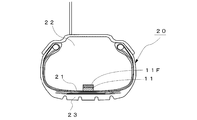
- the acceleration sensor 11 is disposed at a substantially central portion of the inner liner portion 21 of the tire 20 on the tire air chamber 22 side, and detects vibration input from the road surface to the tread 23 of the tire 20 as acceleration.
- the acceleration sensor 11 is arranged so that the detection direction is the tire circumferential direction, and the tire circumferential vibration input from the road surface is detected.
- the position of the acceleration sensor 11 (strictly speaking, the position of the surface of the tread 23 on the outer side in the radial direction of the acceleration sensor 11) is referred to as a measurement point.
- the output of the acceleration sensor 11 is sent to the vehicle control apparatus provided in the vehicle body side by the transmitter 11F, for example.
- the wheel speed sensor 12 detects the rotational speed of the wheel (hereinafter referred to as wheel speed).
- wheel speed For example, a rotor having a gear formed on the outer peripheral portion thereof and rotating together with the wheel, a yoke constituting the rotor and a magnetic circuit
- a known electromagnetic induction type wheel speed sensor that includes a coil that detects a change in magnetic flux of the magnetic circuit and detects a rotation angle of the wheel.
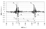
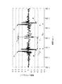
- the vibration waveform detection means 13 detects a time series waveform of vibration in which the vibrations input to the running tire 20 that is the output of the acceleration sensor 11 are arranged in time series. As shown in FIG. 3, in the time-series waveform of vibration, two large positive and negative peaks appear every time the tire rotates. First occurrence peak (here, positive peak) in the time-series waveform of the vibration, the peak of the measurement point is generated when striking the road surface, the peak is depression point P f. The next peak (in this case, a negative peak) is a peak that occurs when the measurement point leaves the road surface, and this peak is the kicking point P k .
- the tread kick position estimating means 14 detects two positive and negative peaks that appear first from the time series waveform of vibration, and the time at which these peaks appear is determined as the position t 11 of the stepping point P f , and It is estimated that the position t 12 of the kicking point P k and the times of the two positive and negative peaks that appear later are respectively the position t 21 of the next stepping point P f and the next kicking point P k . Estimated as position t 22 .
- Contact time and rotation time calculating means 15 the difference between the position t 12 position t 11 and trailing point P k of the depression point P f, a ground measurement point is the time in contact with the road surface time T a calculates a, from the difference between position t 22 position t 12 and trailing point P k of the kick-out point P k of the calculated rotation time T ab is the time at which the tire 20 rotates 1.
- T a t 12 ⁇ t 11
- T b t 21 ⁇ t 12
- T ab t 22 ⁇ t 12 .
- the rotation time T ab may be calculated from a difference between position t 21 position t 11 and the depression point P f of the depression point P f.
- the determination unit 16 includes a contact time ratio calculation unit 161, a comparison determination unit 162, and a stop signal output unit 163.
- the contact time ratio calculation unit 161 calculates a contact time ratio R, which is a ratio between the contact time T a calculated by the contact time / rotation time calculation means 15 and the rotation time T ab .
- the comparison determination unit 162 determines that the position t 11 of the stepping point P f estimated by the stepping kick position estimating unit 14 and the positions t 12 and t 22 of the kicking point P k are all the positions of the actual stepping point. It is determined whether or not it is the position of the kicking point.
- the grounding time ratio R is within a preset grounding time ratio range [R1, R2], and the grounding time ratio R is within the grounding time ratio range (R1 ⁇ R ⁇ R2).
- t 11 estimated by the position estimating portion 14 kicks stepping, t 12, t 22 determines that all the position of the actual position and kicking point depression point (normal position).
- the contact time ratio R is out of the contact time ratio range (R ⁇ R1 or R> R2), the estimated position t 11 of the depression point P f and the positions t 12 and t 22 of the kicking point P k.
- the determination by the comparison determination unit 162 is an erroneous estimation, that is, when the stop signal output unit 163 determines that the estimation of the position of the stepping point P f and the position of the kicking point P k has failed, the road surface state A stop signal, which is a command signal for stopping the road surface estimation operation, is output to the estimating means 18.
- the storage unit 17 stores a map 17M indicating the relationship between the road surface condition obtained in advance and the calculated value of the vibration level.
- the road surface state estimating unit 18 includes a waveform region dividing unit 181, a region signal extracting unit 182, a frequency analyzing unit 183, a vibration level calculating unit 184, and a road surface state estimating unit 185.
- the road surface state is estimated only when it is determined that the estimated stepping point position and kicking point position are the actual stepping point position and kicking point position, and a stop signal is output from the stop signal output unit 163. If it is output, the estimation of the road surface condition is stopped.
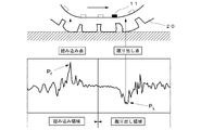
- the waveform area dividing unit 181 uses the position of the stepping point P f or the kicking point P k estimated by the stepping kick position estimating means 14 and the rotation speed of the tire 20 detected by the wheel speed sensor 12 to make one rotation of the tire. In addition to extracting the minute vibration waveform, the vibration waveform is divided into data of two regions, a stepping region and a kicking region as shown in FIG.
- the region signal extraction unit 182 extracts the time series waveform of the vibration level of each region.
- the frequency analysis unit 183 includes frequency analysis means such as an FFT analyzer, and creates a frequency spectrum obtained by frequency analysis of the extracted time series waveform of each vibration level.
- the vibration level calculation unit 184 includes a stepping vibration level V f that is a vibration level in a predetermined frequency band in the frequency spectrum of the stepping area, and a kicking vibration level V k that is a vibration level in the predetermined frequency band in the frequency spectrum of the kicking area. And a vibration level calculation value S is calculated using these vibration levels. Examples of the calculated value S include a ratio of the stepping vibration level V f to the kicking vibration level V k .
- the road surface state estimation unit 185 stores the map 17M indicating the relationship between the road surface state obtained in advance and the calculated vibration level S stored in the storage unit 17, and the vibration level calculated by the vibration level calculation unit 184. From the data of the calculated value S, the state of the road surface on which the vehicle is traveling is estimated.
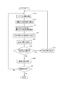
- the tire circumferential direction vibration of the running tire 20 is detected by the acceleration sensor 11 (step S10), and the output is sent to the vibration waveform detecting means 13, and the tire circumferential direction vibration waveform arranged in time series.
- a time series waveform of vibration is obtained (step S11).
- the tread kick position estimating means 14 determines the position t 11 of the first appearing step point P f and the position of the first appearing kick point P k from the time series waveform of vibration as shown in FIG. t 12 and the position t 22 of the kicking point P k that appears later are estimated (step S 12).
- the contact time / rotation time calculation means 15 calculates the contact time T a and the rotation time T ab using t 11 , t 12 , t 22 detected in step S12 (step S13).
- the determination unit 16 after calculating the contact time ratio R is the ratio of the rotation time T ab and the contact time T a (step S14), and the contact time ratio ranges this contact time ratio R is set in advance It is determined whether or not it is within [R1, R2], and whether or not all of t 11 , t 12 , and t 22 detected in step S12 are the actual stepping point P f and kicking point P k.
- the tread kick position is determined (step S15).
- a large input when there is an excessive input (hereinafter referred to as a large input) to the tire 20 such as when overcoming a protrusion or curb, a large peak occurs in the time series waveform as shown in FIG.
- the positions of the stepping point P f and the kicking point P k are erroneously estimated. For example, as shown in the figure, when the position of the large input is estimated as the position of the subsequent kick point P k , the calculated rotation time t ab is shorter than the actual rotation time T ab. Become. Also, if you've estimated that depression point P f after the position of the large input is shorter than the actual contact time contact time t a is T a.
- the grounding time ratio range [R1, R2] is set with respect to the grounding time ratio R, R is compared with the lower limit value R1 of the grounding time ratio range and the upper limit value R2 of the grounding time ratio range, and the grounding time is compared. If it is determined whether the ratio R is in the contact time ratio range, the position t 11 of the stepping point P f estimated by the stepping kick position estimating means 14 and the positions t 12 and t 22 of the kick point P k are determined. It is possible to perform a step kick position determination for determining whether or not the position is an actual step position and a kick point position.
- step S15 If the result of step kick position determination is “normal position” in step S15, the process proceeds to step S16, and the road surface state is estimated using the time series waveform of the vibration level.
- step S17 if the result of the stepping kick position determination is “incorrect estimation”, a stop signal is output to the road surface condition estimating means 18 (step S17), and then the process returns to step S10 and the tire of the running tire 20 is returned.
- step S17 the stop signal is output, the estimation of the road surface condition is stopped.
- step S18 it is determined whether road surface state estimation operation was complete
- the road surface state estimation method in step S16 is as follows. First, a vibration waveform for one rotation of the tire is extracted from the time series waveform of the vibration input to the running tire 20 that is the output of the acceleration sensor 11, and the extracted vibration waveform is divided into a stepping area and a kicking area. After dividing into data of two regions, time series waveforms of vibration levels in each region are extracted. Next, after calculating the vibration levels V f and V k in a predetermined frequency band from the frequency spectrum of each region obtained by frequency analysis of the extracted time series waveform of each vibration level, the vibration level V f and A calculation value S of V k is calculated.
- the estimation and calculation value S the state of the road surface on which the vehicle runs and a map 17M vehicle showing the relationship between the calculated value S r of previously obtained road surface condition and the vibration level.
- the vibration level V f in the frequency band of 8 to 10 kHz is calculated from the frequency spectrum of the stepping area
- the vibration level V k in the frequency band of 1 to 3 kHz is calculated from the frequency spectrum of the kicking area.
- calculated value S V f / V k to investigate whether close to the calculated value S r of which road surface, to estimate the state of the road surface.
- the acceleration sensor 11 is arranged on the tire 20, the tire circumferential vibration of the running tire 20 is detected, and the peak position appearing in the time-varying waveform of the tire circumferential vibration. From this, the position of the tire depression point P f and the position of the kick point P k are estimated, and the contact time T of the tire 20 is determined from the estimated position of the depression point P f and the position of the kick point P k. a , a non-contact time T b , and a rotation time T ab are calculated or any one or more of the calculated contact time T a , non-contact time T b , and rotation time T ab are calculated.
- kick kicking Position determination result is incorrect
- kick kicking Position determination result is incorrect
- the estimation accuracy of the road surface condition can be improved.
- step S15 when the ground contact time or the ground contact length estimated from the ground contact time is outside a predetermined ground contact length range, one or both of the estimated stepping point position and kicking point position is You may make it determine with not the position of an actual depression point, and the position of a kick-out point.
- step S15 when the rotation time or the rotation length estimated from the rotation time is outside the rotation length range set in advance, one or both of the estimated stepping point position and the kicking point position are both May be determined not to be the actual stepping-on point position and kicking-out point position. Thereby, it is possible to determine whether or not the position of the stepping point and the position of the kicking point estimated by a simple method are the actual position of the stepping point and the position of the kicking point.
- step S15 a contact time ratio, which is a ratio between the contact time and the rotation time, is calculated, and when the calculated contact time ratio is outside a preset contact time ratio range, the estimated depression point is calculated. It may be determined that one or both of the position and the kicking point position are not the actual stepping point position and the kicking point position. As a result, it is possible to determine whether the estimated depression point position and kicking point position are the actual depression point position and kicking point position regardless of the wheel speed. The estimation accuracy can be further improved.
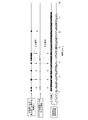
- FIG. 7 is a diagram comparing the result of erroneous estimation in the tread kick position determination according to the present invention and the result of large input detection by the monitoring acceleration sensor described in Patent Document 1, which is apparent from FIG.
- the tread kick position determination according to the present invention has a determination accuracy equal to or higher than the large input detection described in Patent Document 1.
- the acceleration sensor 11 is installed on the tire air chamber 22 side of the inner liner portion 21 of the tire 20 to detect the tire circumferential acceleration.
- the acceleration sensor is attached to the knuckle to accelerate the tire longitudinal acceleration. It is good also as a structure which detects.
- the tire circumferential direction acceleration detected by the acceleration sensor 11 is used to estimate the position of the stepping point P f , the position of the kicking point P k , and the road surface condition.
- tire radial acceleration may be used.
- the present invention is not limited thereto, for example, disclosed in Patent Document 1
- the present invention is applicable to any apparatus that estimates a road surface state using a time-varying waveform of tire vibration during traveling detected by vibration detection means.
- the output of the wheel speed sensor 12 is used to separate the vibration waveform into the kick-out region and the stepping-in region, but the time-series waveform of the vibration waveform is determined from the tire moving radius and the rotation time.
- the wheel speed sensor 12 can be omitted if it is converted into a vibration waveform at a predetermined position and separated into a kick-out area and a depression area. Therefore, the present invention can also be applied to a road surface state estimation device that does not include the wheel speed sensor 12 as a component.
- the tread kick position determination is performed based on the contact time ratio R.
- the tick kick position determination may be performed using any one of the contact time, the non-contact time, and the rotation time.
- the contact length and the rotation length are used instead of the contact time and the rotation time, so that the influence of the wheel speed can be eliminated, so that the accuracy of the stepping kick position determination is further improved. For example, in the case of using the grounding time or the grounding length, it is determined that the estimation is incorrect when the grounding time or the grounding length is out of a preset grounding length range. Further, when the rotation time or the rotation length is used, it is determined that there is an erroneous estimation when the rotation time or the rotation length is outside the preset rotation length range.
- one or both of the position of the stepping point and the position of the kicking point estimated from the contact time Ta and the rotation time Tab is the actual position of the stepping point and the position of the kicking point. It was determined whether the ground outside time T b is, since the difference between the rotation time T ab and contact time T a, the contact time T a and the ground outside the time T b, or ground out time T b Needless to say, it is possible to determine from the rotation time T ab whether one or both of the estimated depression point position and kicking point position are the actual depression point position and the kicking point position. Absent.
Landscapes
- Engineering & Computer Science (AREA)
- Mechanical Engineering (AREA)
- Physics & Mathematics (AREA)
- Transportation (AREA)
- Analytical Chemistry (AREA)
- Health & Medical Sciences (AREA)
- Life Sciences & Earth Sciences (AREA)
- Chemical & Material Sciences (AREA)
- Acoustics & Sound (AREA)
- Biochemistry (AREA)
- General Health & Medical Sciences (AREA)
- General Physics & Mathematics (AREA)
- Immunology (AREA)
- Pathology (AREA)
- Control Of Driving Devices And Active Controlling Of Vehicle (AREA)
- Tires In General (AREA)
- Length Measuring Devices With Unspecified Measuring Means (AREA)
Abstract
La présente invention a pour objet de mettre en œuvre un procédé permettant de déterminer avec une grande précision si oui ou non une entrée importante a été appliquée à un pneu et permettant d'estimer l'état de la surface d'une route sans avoir à augmenter le nombre de capteurs. Un capteur d'accélération est disposé sur le pneu et des vibrations du pneu en mouvement sont détectées. La position du point de dépression et la position du point d'arrêt du pneu sont estimées en fonction de positions de pic apparaissant dans la forme d'onde variant dans le temps des vibrations, et si oui ou non les positions estimées du point de dépression et du point d'arrêt sont les positions réelles du point de dépression et du point d'arrêt est déterminé à l'aide de l'un quelconque ou plusieurs des éléments suivants : le temps de contact entre le pneu et le sol, le temps de non-contact avec le sol, et le temps de rotation calculé à partir des positions estimées du point de dépression et du point d'arrêt. Si le résultat de la détermination de la position de dépression et de la position d'arrêt indique que l'estimation a été erronée, l'estimation de l'état de la surface de la route n'est pas effectuée.
Priority Applications (3)
| Application Number | Priority Date | Filing Date | Title |
|---|---|---|---|
| EP15759202.3A EP3115232B1 (fr) | 2014-03-07 | 2015-01-05 | Procédé d'estimation de l'état de la surface de la route |
| CN201580012512.2A CN106061761B (zh) | 2014-03-07 | 2015-01-05 | 路面状态估计方法 |
| US15/122,993 US10059316B2 (en) | 2014-03-07 | 2015-01-05 | Road surface condition estimating method |
Applications Claiming Priority (2)
| Application Number | Priority Date | Filing Date | Title |
|---|---|---|---|
| JP2014045591A JP6382534B2 (ja) | 2014-03-07 | 2014-03-07 | 路面状態推定方法 |
| JP2014-045591 | 2014-03-07 |
Publications (1)
| Publication Number | Publication Date |
|---|---|
| WO2015133155A1 true WO2015133155A1 (fr) | 2015-09-11 |
Family
ID=54054967
Family Applications (1)
| Application Number | Title | Priority Date | Filing Date |
|---|---|---|---|
| PCT/JP2015/050029 Ceased WO2015133155A1 (fr) | 2014-03-07 | 2015-01-05 | Procédé d'estimation de l'état de la surface de la route |
Country Status (5)
| Country | Link |
|---|---|
| US (1) | US10059316B2 (fr) |
| EP (1) | EP3115232B1 (fr) |
| JP (1) | JP6382534B2 (fr) |
| CN (1) | CN106061761B (fr) |
| WO (1) | WO2015133155A1 (fr) |
Cited By (2)
| Publication number | Priority date | Publication date | Assignee | Title |
|---|---|---|---|---|
| CN108780016A (zh) * | 2016-03-11 | 2018-11-09 | 株式会社普利司通 | 轮胎载荷推断方法及轮胎载荷推断装置 |
| JP2020172825A (ja) * | 2019-04-12 | 2020-10-22 | 株式会社ブリヂストン | 橋梁ジョイントの劣化状態推定方法とその装置 |
Families Citing this family (13)
| Publication number | Priority date | Publication date | Assignee | Title |
|---|---|---|---|---|
| JP6544302B2 (ja) * | 2016-06-22 | 2019-07-17 | 株式会社Soken | 路面状況推定装置 |
| JP6620787B2 (ja) * | 2016-08-11 | 2019-12-18 | 株式会社デンソー | 路面状態推定装置 |
| JP6783184B2 (ja) * | 2017-05-12 | 2020-11-11 | 株式会社ブリヂストン | 路面状態判別方法及び路面状態判別装置 |
| DE102017006844B4 (de) * | 2017-07-18 | 2019-04-11 | Bomag Gmbh | Bodenverdichter und Verfahren zur Bestimmung von Untergrundeigenschaften mittels eines Bodenverdichters |
| JP7009098B2 (ja) * | 2017-07-19 | 2022-01-25 | 株式会社ブリヂストン | 路面状態推定方法 |
| US20190118592A1 (en) * | 2017-10-19 | 2019-04-25 | Infineon Technologies Ag | Method, Tire-Mounted TPMS Component, and Machine Readable Storage or Computer Program for Determining a Duration of at Least one Contact Patch Event of a Rolling Tire |
| US10549587B2 (en) | 2017-10-19 | 2020-02-04 | Infineon Technologies Ag | Method, component, tire-mounted TPMS module, TPMS system, and machine readable storage or computer program for determining time information of at least one contact patch event of a rolling tire, method for locating a tire |
| JP6996710B2 (ja) * | 2018-02-14 | 2022-02-03 | 学校法人神奈川大学 | 回転体への入力パワー推定システム及び入力パワー推定方法、並びに、当接面状態判定システム及び移動体機器制御システム |
| WO2020071249A1 (fr) | 2018-10-05 | 2020-04-09 | 株式会社ブリヂストン | Procédé d'estimation d'usure de pneu |
| EP3696395A1 (fr) * | 2019-02-15 | 2020-08-19 | Toyota Jidosha Kabushiki Kaisha | Système de détection d'état pour moteur à combustion interne, dispositif d'analyse de données et véhicule |
| US11255282B2 (en) * | 2019-02-15 | 2022-02-22 | Toyota Jidosha Kabushiki Kaisha | State detection system for internal combustion engine, data analysis device, and vehicle |
| FR3097962B1 (fr) * | 2019-06-28 | 2021-06-11 | Ifp Energies Now | Procédé de caractérisation de l’état d’une route |
| JP2024097561A (ja) * | 2023-01-06 | 2024-07-19 | 横浜ゴム株式会社 | 路面状態判定方法及び路面状態判定装置 |
Citations (3)
| Publication number | Priority date | Publication date | Assignee | Title |
|---|---|---|---|---|
| JP2002002472A (ja) * | 2000-06-16 | 2002-01-09 | Bridgestone Corp | 路面摩擦係数の推定方法と路面摩擦係数推定装置、路面状態推定装置、路面滑り警告装置、及び車輌制御方法と車輌制御装置 |
| JP2007106243A (ja) * | 2005-10-13 | 2007-04-26 | Toyota Motor Corp | タイヤ情報取得装置およびタイヤ情報取得方法 |
| JP2008302848A (ja) * | 2007-06-08 | 2008-12-18 | Nissan Motor Co Ltd | タイヤ状態推定装置、自動車及びタイヤ状態推定方法 |
Family Cites Families (13)
| Publication number | Priority date | Publication date | Assignee | Title |
|---|---|---|---|---|
| EP0818683B1 (fr) | 1992-12-18 | 2003-04-16 | Siemens Aktiengesellschaft | Procédé de détection de mauvais état des routes |
| EP1219515B1 (fr) * | 2000-06-23 | 2011-01-19 | Kabushiki Kaisha Bridgestone | Procede d'estimation de l'etat de marche d'un vehicule, dispositif d'estimation de l'etat de marche d'un vehicule, dispositif de commande de vehicule, et bandage de roue |
| JP4367613B2 (ja) * | 2003-09-25 | 2009-11-18 | 横浜ゴム株式会社 | タイヤ踏面状態測定装置及び測定方法 |
| EP1897706B1 (fr) * | 2005-06-17 | 2014-12-24 | Kabushiki Kaisha Bridgestone | Procédé d'évaluation de l'état de la surface de la chaussée, pneu d'évaluation de l'état de la surface de la chaussée, dispositif d'évaluation de l'état de la surface de la chaussée, et dispositif de contrôle |
| JP4817753B2 (ja) * | 2005-08-22 | 2011-11-16 | 株式会社ブリヂストン | 路面状態推定方法、路面状態推定装置、及び、車両制御装置 |
| EP1878596B1 (fr) * | 2006-07-11 | 2013-06-05 | The Yokohama Rubber Co., Ltd. | Appareil et procédé pour l'évaluation du degré de sécurité lors du déplacement d'un véhicule |
| DE102007039242A1 (de) | 2007-08-20 | 2009-02-26 | Robert Bosch Gmbh | Verfahren zum Betrieb eines Sensors an oder in einem Fahrzeugreifen und Sensoranordnung |
| EP2301769B1 (fr) | 2008-06-25 | 2017-01-11 | Kabushiki Kaisha Bridgestone | Procédé et dispositif d évaluation d usure de pneumatique |
| US8767843B2 (en) * | 2008-11-10 | 2014-07-01 | Motorola Mobility Llc | Employing cell-specific and user entity-specific reference symbols in an orthogonal frequency-division multiple access |
| JP5557569B2 (ja) | 2010-03-24 | 2014-07-23 | 株式会社ブリヂストン | 路面状態推定方法 |
| JP5657917B2 (ja) | 2010-05-19 | 2015-01-21 | 株式会社ブリヂストン | 路面状態推定方法 |
| JP5788710B2 (ja) | 2011-05-16 | 2015-10-07 | 株式会社ブリヂストン | 路面摩擦係数推定方法、車両制御方法、及び、路面摩擦係数推定装置 |
| CN103717469B (zh) * | 2011-07-20 | 2016-08-03 | 株式会社普利司通 | 路面状态估计方法和路面状态估计设备 |
-
2014
- 2014-03-07 JP JP2014045591A patent/JP6382534B2/ja active Active
-
2015
- 2015-01-05 CN CN201580012512.2A patent/CN106061761B/zh active Active
- 2015-01-05 WO PCT/JP2015/050029 patent/WO2015133155A1/fr not_active Ceased
- 2015-01-05 US US15/122,993 patent/US10059316B2/en active Active
- 2015-01-05 EP EP15759202.3A patent/EP3115232B1/fr active Active
Patent Citations (3)
| Publication number | Priority date | Publication date | Assignee | Title |
|---|---|---|---|---|
| JP2002002472A (ja) * | 2000-06-16 | 2002-01-09 | Bridgestone Corp | 路面摩擦係数の推定方法と路面摩擦係数推定装置、路面状態推定装置、路面滑り警告装置、及び車輌制御方法と車輌制御装置 |
| JP2007106243A (ja) * | 2005-10-13 | 2007-04-26 | Toyota Motor Corp | タイヤ情報取得装置およびタイヤ情報取得方法 |
| JP2008302848A (ja) * | 2007-06-08 | 2008-12-18 | Nissan Motor Co Ltd | タイヤ状態推定装置、自動車及びタイヤ状態推定方法 |
Cited By (5)
| Publication number | Priority date | Publication date | Assignee | Title |
|---|---|---|---|---|
| CN108780016A (zh) * | 2016-03-11 | 2018-11-09 | 株式会社普利司通 | 轮胎载荷推断方法及轮胎载荷推断装置 |
| EP3428597A4 (fr) * | 2016-03-11 | 2019-03-27 | Bridgestone Corporation | Procédé et dispositif d'estimation de la charge d'un pneu |
| US10684161B2 (en) | 2016-03-11 | 2020-06-16 | Bridgestone Corporation | Tire load estimation method and tire load estimation device |
| JP2020172825A (ja) * | 2019-04-12 | 2020-10-22 | 株式会社ブリヂストン | 橋梁ジョイントの劣化状態推定方法とその装置 |
| JP7148452B2 (ja) | 2019-04-12 | 2022-10-05 | 株式会社ブリヂストン | 橋梁ジョイントの劣化状態推定方法とその装置 |
Also Published As
| Publication number | Publication date |
|---|---|
| EP3115232A1 (fr) | 2017-01-11 |
| JP6382534B2 (ja) | 2018-08-29 |
| EP3115232A4 (fr) | 2017-03-08 |
| US10059316B2 (en) | 2018-08-28 |
| EP3115232B1 (fr) | 2019-07-10 |
| CN106061761A (zh) | 2016-10-26 |
| CN106061761B (zh) | 2018-11-27 |
| JP2015168362A (ja) | 2015-09-28 |
| US20170072922A1 (en) | 2017-03-16 |
Similar Documents
| Publication | Publication Date | Title |
|---|---|---|
| JP6382534B2 (ja) | 路面状態推定方法 | |
| JP5956250B2 (ja) | タイヤ偏摩耗検知方法及びタイヤ偏摩耗検知装置 | |
| JP5165603B2 (ja) | タイヤ走行状態推定方法、定常走行状態推定装置、タイヤ摩耗推定方法とその装置 | |
| CN105793687B (zh) | 轮胎异常磨损的估计方法和估计设备 | |
| US9045117B2 (en) | Road surface condition estimating method, vehicle control method, and road surface condition estimating apparatus | |
| JP5495971B2 (ja) | タイヤ内部故障判定方法 | |
| JP5072463B2 (ja) | タイヤの摩耗検知方法及びタイヤの摩耗検知装置 | |
| JP5898519B2 (ja) | タイヤ摩耗量推定方法及びタイヤ摩耗量推定装置 | |
| JP4817753B2 (ja) | 路面状態推定方法、路面状態推定装置、及び、車両制御装置 | |
| US8299909B2 (en) | Apparatus, method and program for detecting decrease in tire air pressure including means to reject data | |
| CN111033201B (zh) | 轮胎载荷估计方法和轮胎载荷估计装置 | |
| WO2009157516A1 (fr) | Procédé et dispositif d’évaluation d’usure de pneumatique | |
| US7937204B2 (en) | Brake control method and brake control device | |
| US7957879B2 (en) | Brake control method and brake control device | |
| WO2020044739A1 (fr) | Procédé de détection d'usure de pneu et appareil de détection d'usure de pneu | |
| JP2008162392A (ja) | タイヤ接地状態推定方法、タイヤ接地状態推定装置、タイヤ、及び、車輌制御装置 | |
| JP4946174B2 (ja) | タイヤの接地長算出方法及びタイヤの接地長算出装置 |
Legal Events
| Date | Code | Title | Description |
|---|---|---|---|
| 121 | Ep: the epo has been informed by wipo that ep was designated in this application |
Ref document number: 15759202 Country of ref document: EP Kind code of ref document: A1 |
|
| WWE | Wipo information: entry into national phase |
Ref document number: 15122993 Country of ref document: US |
|
| NENP | Non-entry into the national phase |
Ref country code: DE |
|
| REEP | Request for entry into the european phase |
Ref document number: 2015759202 Country of ref document: EP |
|
| WWE | Wipo information: entry into national phase |
Ref document number: 2015759202 Country of ref document: EP |