WO2015136868A1 - Appareil d'enregistrement - Google Patents
Appareil d'enregistrement Download PDFInfo
- Publication number
- WO2015136868A1 WO2015136868A1 PCT/JP2015/000970 JP2015000970W WO2015136868A1 WO 2015136868 A1 WO2015136868 A1 WO 2015136868A1 JP 2015000970 W JP2015000970 W JP 2015000970W WO 2015136868 A1 WO2015136868 A1 WO 2015136868A1
- Authority
- WO
- WIPO (PCT)
- Prior art keywords
- ink
- control unit
- electronic component
- cable
- liquid
- Prior art date
- Legal status (The legal status is an assumption and is not a legal conclusion. Google has not performed a legal analysis and makes no representation as to the accuracy of the status listed.)
- Ceased
Links
Images


Classifications
-
- B—PERFORMING OPERATIONS; TRANSPORTING
- B41—PRINTING; LINING MACHINES; TYPEWRITERS; STAMPS
- B41J—TYPEWRITERS; SELECTIVE PRINTING MECHANISMS, i.e. MECHANISMS PRINTING OTHERWISE THAN FROM A FORME; CORRECTION OF TYPOGRAPHICAL ERRORS
- B41J2/00—Typewriters or selective printing mechanisms characterised by the printing or marking process for which they are designed
- B41J2/005—Typewriters or selective printing mechanisms characterised by the printing or marking process for which they are designed characterised by bringing liquid or particles selectively into contact with a printing material
- B41J2/01—Ink jet
- B41J2/17—Ink jet characterised by ink handling
- B41J2/175—Ink supply systems ; Circuit parts therefor
- B41J2/17503—Ink cartridges
- B41J2/17526—Electrical contacts to the cartridge
-
- B—PERFORMING OPERATIONS; TRANSPORTING
- B41—PRINTING; LINING MACHINES; TYPEWRITERS; STAMPS
- B41J—TYPEWRITERS; SELECTIVE PRINTING MECHANISMS, i.e. MECHANISMS PRINTING OTHERWISE THAN FROM A FORME; CORRECTION OF TYPOGRAPHICAL ERRORS
- B41J19/00—Character- or line-spacing mechanisms
- B41J19/005—Cable or belt constructions for driving print, type or paper-carriages, e.g. attachment, tensioning means
-
- B—PERFORMING OPERATIONS; TRANSPORTING
- B41—PRINTING; LINING MACHINES; TYPEWRITERS; STAMPS
- B41J—TYPEWRITERS; SELECTIVE PRINTING MECHANISMS, i.e. MECHANISMS PRINTING OTHERWISE THAN FROM A FORME; CORRECTION OF TYPOGRAPHICAL ERRORS
- B41J2/00—Typewriters or selective printing mechanisms characterised by the printing or marking process for which they are designed
- B41J2/005—Typewriters or selective printing mechanisms characterised by the printing or marking process for which they are designed characterised by bringing liquid or particles selectively into contact with a printing material
- B41J2/01—Ink jet
- B41J2/17—Ink jet characterised by ink handling
- B41J2/175—Ink supply systems ; Circuit parts therefor
- B41J2/17503—Ink cartridges
- B41J2/17506—Refilling of the cartridge
- B41J2/17509—Whilst mounted in the printer
-
- B—PERFORMING OPERATIONS; TRANSPORTING
- B41—PRINTING; LINING MACHINES; TYPEWRITERS; STAMPS
- B41J—TYPEWRITERS; SELECTIVE PRINTING MECHANISMS, i.e. MECHANISMS PRINTING OTHERWISE THAN FROM A FORME; CORRECTION OF TYPOGRAPHICAL ERRORS
- B41J2/00—Typewriters or selective printing mechanisms characterised by the printing or marking process for which they are designed
- B41J2/005—Typewriters or selective printing mechanisms characterised by the printing or marking process for which they are designed characterised by bringing liquid or particles selectively into contact with a printing material
- B41J2/01—Ink jet
- B41J2/17—Ink jet characterised by ink handling
- B41J2/175—Ink supply systems ; Circuit parts therefor
- B41J2/17503—Ink cartridges
- B41J2/1752—Mounting within the printer
-
- B—PERFORMING OPERATIONS; TRANSPORTING
- B41—PRINTING; LINING MACHINES; TYPEWRITERS; STAMPS
- B41J—TYPEWRITERS; SELECTIVE PRINTING MECHANISMS, i.e. MECHANISMS PRINTING OTHERWISE THAN FROM A FORME; CORRECTION OF TYPOGRAPHICAL ERRORS
- B41J2/00—Typewriters or selective printing mechanisms characterised by the printing or marking process for which they are designed
- B41J2/005—Typewriters or selective printing mechanisms characterised by the printing or marking process for which they are designed characterised by bringing liquid or particles selectively into contact with a printing material
- B41J2/01—Ink jet
- B41J2/17—Ink jet characterised by ink handling
- B41J2/175—Ink supply systems ; Circuit parts therefor
- B41J2/17503—Ink cartridges
- B41J2/17543—Cartridge presence detection or type identification
- B41J2/17546—Cartridge presence detection or type identification electronically
-
- B—PERFORMING OPERATIONS; TRANSPORTING
- B41—PRINTING; LINING MACHINES; TYPEWRITERS; STAMPS
- B41J—TYPEWRITERS; SELECTIVE PRINTING MECHANISMS, i.e. MECHANISMS PRINTING OTHERWISE THAN FROM A FORME; CORRECTION OF TYPOGRAPHICAL ERRORS
- B41J2/00—Typewriters or selective printing mechanisms characterised by the printing or marking process for which they are designed
- B41J2/005—Typewriters or selective printing mechanisms characterised by the printing or marking process for which they are designed characterised by bringing liquid or particles selectively into contact with a printing material
- B41J2/01—Ink jet
- B41J2/17—Ink jet characterised by ink handling
- B41J2/175—Ink supply systems ; Circuit parts therefor
- B41J2/17503—Ink cartridges
- B41J2/17553—Outer structure
-
- B—PERFORMING OPERATIONS; TRANSPORTING
- B41—PRINTING; LINING MACHINES; TYPEWRITERS; STAMPS
- B41J—TYPEWRITERS; SELECTIVE PRINTING MECHANISMS, i.e. MECHANISMS PRINTING OTHERWISE THAN FROM A FORME; CORRECTION OF TYPOGRAPHICAL ERRORS
- B41J2/00—Typewriters or selective printing mechanisms characterised by the printing or marking process for which they are designed
- B41J2/005—Typewriters or selective printing mechanisms characterised by the printing or marking process for which they are designed characterised by bringing liquid or particles selectively into contact with a printing material
- B41J2/01—Ink jet
- B41J2/21—Ink jet for multi-colour printing
-
- B—PERFORMING OPERATIONS; TRANSPORTING
- B41—PRINTING; LINING MACHINES; TYPEWRITERS; STAMPS
- B41J—TYPEWRITERS; SELECTIVE PRINTING MECHANISMS, i.e. MECHANISMS PRINTING OTHERWISE THAN FROM A FORME; CORRECTION OF TYPOGRAPHICAL ERRORS
- B41J29/00—Details of, or accessories for, typewriters or selective printing mechanisms not otherwise provided for
- B41J29/02—Framework
-
- B—PERFORMING OPERATIONS; TRANSPORTING
- B41—PRINTING; LINING MACHINES; TYPEWRITERS; STAMPS
- B41J—TYPEWRITERS; SELECTIVE PRINTING MECHANISMS, i.e. MECHANISMS PRINTING OTHERWISE THAN FROM A FORME; CORRECTION OF TYPOGRAPHICAL ERRORS
- B41J29/00—Details of, or accessories for, typewriters or selective printing mechanisms not otherwise provided for
- B41J29/12—Guards, shields or dust excluders
- B41J29/13—Cases or covers
Definitions
- the present invention relates to a recording apparatus for recording on a medium.
- Some ink jet printers are provided with an external ink supply apparatus outside the apparatus main body, as disclosed in Patent Document 1, to enable an increase in the ink storable amount.
- the ink bag provided in the external ink supply device and the printer body are connected by an ink supply tube.
- an ink container (ink bag) is provided for each ink color in the ink container (the external ink supply device in the example of Patent Document 1), and the ink container can be replaced. Furthermore, for each ink container, a storage medium (electronic component) that holds information such as the type (color, capacity) of the ink and the remaining amount of ink may be provided for each ink bag. In this case, the control unit (main substrate) of the printer and the storage medium are electrically connected by a cable.
- the ink storage portion when the ink storage portion is provided outside the apparatus main body, a configuration is also conceivable in which the ink storage portion is attached to the side surface of the housing constituting the appearance of the printer. In the case of such a configuration, when performing maintenance or the like of the printer main body, it is necessary to once remove the ink storage unit from the housing.
- the cable is wired without an extra length, it is necessary to remove the cable from the control unit (main substrate) of the printer before removing the ink storage unit, which requires time and labor and time. .
- the cable has an extra length in order to avoid such a deterioration in maintainability, it is not preferable because it is susceptible to noise as the cable length increases.
- the effect of noise accompanying an increase in cable length is meant to include both the passive case where the cable picks up noise from the outside and the active case where the cable emits noise from the cable. .
- the present invention has been made in view of such a situation, and an object thereof is to achieve both improvement in maintainability and suppression of performance degradation of the apparatus in a configuration including an ink storage unit outside the apparatus main body. It is in.
- a recording apparatus for solving the above problems includes: a recording head capable of ejecting a liquid to a medium; a control unit for controlling the recording head; the recording head and the control unit A case that is attached to the outside of the case, a case that covers a structure including the liquid container, a liquid container that stores the liquid, and an electronic component that holds information of the liquid container; A tube for guiding the liquid from the body to the inside of the housing, and an electrical wiring electrically connecting the control unit and the electronic component, the electrical wiring including a connecting portion for connecting a cable, and A control unit-side cable that configures wiring on the control unit side with respect to a connection unit; and an electronic component-side cable that configures wiring on the electronic component side with respect to the connection unit; Parts side At least one of the holes can be connected and disconnected at the connection portion, the case is formed with an opening through which the electrical wiring passes, and the connection portion is provided between the opening and the electronic component. It is characterized by
- the electrical wiring electrically connecting the control unit and the electronic component includes a connection unit, and the electronic component side cable or the control unit side cable can be disconnected at the connection unit.
- a recording head capable of ejecting a liquid to a medium
- a control unit for controlling the recording head
- a case covering a structure including the recording head and the control unit the liquid
- the liquid A case attached to the outside of the case for storing a liquid container for containing the liquid, and an electronic component for holding information of the liquid container, and the liquid is introduced from the liquid container into the inside of the case It comprises: a tube; and an electrical wiring for electrically connecting the control unit and the electronic component, wherein the electrical wiring comprises a connection portion for connecting a cable, and a wiring on the control portion side with respect to the connection portion.
- Control unit-side cable, and an electronic component-side cable that configures wiring on the electronic component side with respect to the connection unit, and at least one of the control unit-side cable and the electronic component side cable is the connection unit are possible Oite connection and disconnection, said openings in the housing through the electrical wires are formed, the connecting portion, characterized in that provided between the opening and the control unit.
- the electrical wiring electrically connecting the control unit and the electronic component includes a connection unit, and the electronic component side cable or the control unit side cable can be disconnected at the connection unit.
- connection portion is constituted by a circuit board.
- a plurality of the liquid containers are provided inside the case, and the electronic component and the electronic component side cable are provided for each of the plurality of liquid containers.
- the circuit board is capable of connecting a plurality of the electronic component side cables and the one control unit side cable, and transmits and receives information between the plurality of electronic components and the control unit on the one control unit side It is characterized by relaying using a cable.
- the plurality of electronic component side cables are connected to the circuit board, that is, aggregated, and connected to the control unit by the one control unit side cable. Therefore, the cable length can be shortened as compared with the configuration in which each of the plurality of electronic components is connected to the control unit, and the influence of noise can be minimized.
- the circuit board is fixed to the inside of the opening. According to this aspect, since the circuit board is fixed to the inside of the opening, that is, at a position close to the opening, the connection and disconnection operation of the electronic component side cable or the control unit side cable can be performed more easily. be able to.
- the plurality of electronic component side cables are wired in parallel without overlapping in the inside of the case.
- the plurality of electronic component side cables are wired in parallel without overlapping in the inside of the case, the plurality of electronic component side cables are not affected by noise each other, or The effects of noise can be reduced.
- the connecting portion is constituted by a connector. According to this aspect, since the connection portion is configured by the connector, the structure of the connection portion can be simplified and the cost can be reduced.
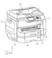
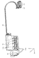
- FIG. 1 is an external perspective view of a printer according to a first embodiment.
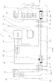
- FIG. 2 is a block diagram showing an outline of electrical wiring in the printer according to the present invention.
- FIG. 6 is a perspective view showing the printer according to the first embodiment with the case for storing the ink container of black ink opened.
- FIG. 6 is a perspective view showing the printer according to the first embodiment in which the case for storing the ink container of color ink is opened.
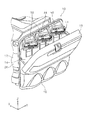
- FIG. 4 is an enlarged view of the periphery of the mounting portion of the ink container in FIG. 3;
- FIG. 3 is an external perspective view of an ink container.
- FIG. 7 is an enlarged perspective view of a mounting portion of the ink container to the ink container storage case.
- FIG. 7 is an enlarged perspective view of a mounting portion in an ink container storage case for storing an ink container of black ink.
- FIG. 7 is an enlarged perspective view of a mounting portion in an ink container storage case for storing an ink container of color ink.
- FIG. 6 is a perspective view of an openable cover in the ink container storage case.
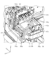
- FIG. 2 is a perspective view showing a supply path of black ink in the printer according to the first embodiment.
- FIG. 2 is a perspective view showing a supply path of color ink in the printer according to the first embodiment.
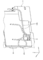
- FIG. 6 is a side view showing a supply path of black ink from the ink container storage case storing the ink container of black ink to the inside of the housing.
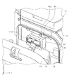
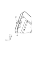
- FIG. 10 is a perspective view showing an opening provided on the side of the housing and leading an ink tube of black ink extending from the ink container storage case into the housing.
- FIG. 15 is an enlarged perspective view of the opening in FIG. 14;
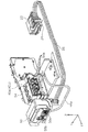
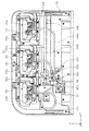
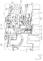
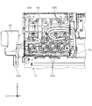
- FIG. 1 is a plan view of a structure of a printer according to a first embodiment.
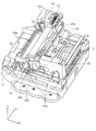
- FIG. 7 is a perspective view showing an ink relay portion provided in the structure.
- FIG. 6 is a side view showing a supply path of color ink from an ink container storage case for storing an ink container of color ink into the housing.
- FIG. 7 is an enlarged view of the vicinity of the opening in the ink container storage case.
- FIG. 10 is a perspective view showing an opening which is provided on the side of the housing and guides a plurality of ink tubes of color ink extending from the ink container storage case into the housing.
- FIG. 21 is a perspective view showing the arrangement of color ink in the structure near the opening in FIG. 20.
- Sectional drawing which shows the state of the ink tube of the color ink arrange
- FIG. 7 is a view showing the arrangement of the ink tube when the ink relay portion provided in the structure is viewed from the front.
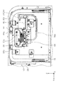
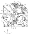
- FIG. 5 is a view of a cable arrangement for transmitting information from an ink container in the printer according to the first embodiment as viewed from the front side of the apparatus.
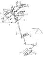
- FIG. 6 is a view of a cable arrangement for transmitting information from an ink container in the printer according to the first embodiment as viewed from the rear side of the apparatus.
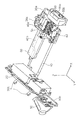
- FIG. 10 is a perspective view showing the arrangement of cables from the junction board to the control unit in the structure.
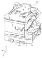
- FIG. 8 is an external perspective view of a printer according to a second embodiment.
- FIG. 10 is a perspective view showing a supply path of black ink in the printer according to the second embodiment.
- FIG. 8 is a perspective view showing a supply path of color ink in the printer according to the second embodiment.
- FIG. 10 is a perspective view showing an opening provided on the side of the housing and leading an ink tube of black ink extending from the ink container storage case into the housing. The enlarged perspective view of the opening in FIG. FIG.
- FIG. 7 is a view showing the arrangement of the ink tube when the ink relay portion provided in the structure is viewed from the front.
- FIG. 6 is a side view showing a supply path of color ink from an ink container storage case for storing an ink container of color ink into the housing.
- FIG. 10 is a perspective view showing an opening which is provided on the side of the housing and guides a plurality of ink tubes of color ink extending from the ink container storage case into the housing.
- FIG. 35 is a perspective view showing the ink tube arrangement of color ink in the structure near the opening in FIG. 34.
- FIG. 10 is a back side perspective view of a structure in a printer according to a second embodiment. The perspective view which looked at the ink relay part from the right side.
- FIG. 7 is a perspective view of a carriage movement region and an ink relay portion in the structure as viewed from the front.
- FIG. 14 is a left side view of a cable arrangement for transmitting information from the ink container in the printer according to the second embodiment. Explanatory drawing which shows the arrangement
- FIG. 7 is a perspective view showing cable routing in the structure.
- FIG. 7 is a perspective view showing cable routing in the vicinity of the control unit in the structure.
- FIG. 1 is an external perspective view of a printer (hereinafter referred to as a printer 10) according to the first embodiment
- FIG. 2 is a block diagram showing an outline of electrical wiring in the printer 10
- FIG. FIG. 4 is a perspective view showing a state in which the case for storing the ink container of ink is opened
- FIG. 4 is a perspective view showing a state in which the case for storing the ink container for color ink in the printer 10 is opened.
- FIG. 5 is an enlarged view of the periphery of the mounting portion of the ink container in FIG.
- FIG. 6 is an external perspective view of the ink container
- FIG. 7 is an enlarged perspective view of a mounting portion of the ink container to the ink container storage case
- FIG. 8 is an ink container for storing the ink container of black ink
- FIG. 9 is an enlarged perspective view of the mounting portion in the ink container storage case for storing the ink container of the color ink
- FIG. 10 is an open / close cover in the ink container storage case.
- FIG. 11 is a perspective view showing a supply path of black ink in the printer 10
- FIG. 12 is a perspective view showing a supply path of color ink in the printer 10
- FIG. 13 is an ink containing ink container for black ink.
- FIG. 14 is a side view showing a supply path of black ink from the body storage case to the inside of the case, and FIG. 14 shows an opening provided on the side of the case and guiding the ink tube of black ink extending from the ink container storage case into the case
- FIG. 15 is a perspective view, and FIG. 15 is an enlarged perspective view of the opening in FIG.
- FIG. 16 is a plan view of the structure of the printer 10
- FIG. 17 is a perspective view showing an ink relay portion provided in the structure
- FIG. 18 is an ink container storage case for storing color ink containers.
- 19 is a side view showing the supply path of color ink from the inside of the case to the inside of the case
- FIG. 19 is an enlarged view of the vicinity of the opening in the ink container storage case
- FIG. 18 is a perspective view showing an opening for guiding a plurality of ink tubes of color ink extending therefrom into the housing.
- FIG. 21 is a perspective view showing the ink tube arrangement of the color ink in the structure near the opening in FIG. 20, and FIG. 22 is the ink tube of the color ink arranged under the frame crossing in the width direction of the structure in the structure.
- FIG. 23 is a cross-sectional view showing the state of the ink tube, and FIG. 23 is a view showing the arrangement of the ink tube when the ink relay portion provided in the structure is viewed from the front
- FIG. FIG. 25 is a view of the cable routing for transmitting the image viewed from the front side of the device, FIG. 25 is a view of the cable routing for transmitting information from the ink container in the printer 10 from the rear side of the device, and FIG. It is a perspective view showing arrangement of a cable from a junction board in a body to a control part.
- the X direction is the scanning direction of the recording head
- the Y direction is the depth direction and paper conveyance direction of the recording apparatus
- the Z direction is the distance (gap) between the recording head and the paper. It shows the changing direction, that is, the device height direction.
- the ⁇ Y direction is the front side of the device
- the + Y direction side is the rear side of the device.
- the printer 10 includes an apparatus main body 12 and an ink container as a "case” for containing an ink as a “liquid” and containing an ink container 14 (see Fig. 6) as a "liquid container”. Storage cases 16 and 18 are provided.
- the device body 12 includes a structure 13 (see FIG. 26) and a housing 26 (see FIG. 1) that covers the structure 13.
- the structural body 13 includes a control unit 20 and a carriage 22.
- the carriage 22 is provided with a recording head 24 capable of ejecting ink to the medium.
- the carriage 22 is configured to be movable in the X-axis direction in FIG. 1 under the control of the control unit 20 in the apparatus main body 12, that is, in the structure 13.
- the ink container storage cases 16 and 18 are provided outside the housing 26.
- the ink container storage cases 16 and 18 are detachably mounted on both side surfaces of the housing 26 in the X-axis direction.
- the ink container storage cases 16 and 18 include covers 19 and 19.
- the covers 19 and 19 are configured to be able to open and close with respect to the ink container storage cases 16 and 18, respectively (for example, FIGS. 3 and 4).
- the ink containers 14 are stored in the ink containers 14 when the covers 19 are open with respect to the ink containers 16 (see FIGS. 3 and 4). Exchange is possible.
- the ink container 14 containing the black ink is detachably stored in the ink container storage case 16. Further, in the ink container storage case 18, a plurality of ink containers 14 that respectively store ink of each color of magenta, cyan and yellow are detachably stored.
- a CSIC substrate 28 as an “electronic component” is attached to the ink container 14 of each color (black, magenta, cyan, yellow) (see FIG. 7).
- the CSIC substrate 28 includes a storage element for storing information such as the type of ink contained in the ink container 14 and the remaining amount of ink, and holds the information of the ink container 14.
- the electrical wiring 29 is configured to include flat cables 30a and 30b, relay boards 36a and 36b, flat cables 40a and 40b, and a merging board 42.
- One end of a nine-core flat cable 30a (see the thin dashed-dotted line in FIG. 2) as the “electronic component side cable” is electrically connected to the CSIC substrate 28 corresponding to the black ink.
- the flat cable 30 a passes through the opening 32 (see FIG. 13) provided in the ink container storage case 16 and the opening 34 (see FIG. 14) facing the opening 32 and provided in the side surface of the housing 26. It extends from the ink container storage case 16 into the housing 26.
- the other end of the flat cable 30 a is connected to the relay board 36 a as a “connection portion” in the structure 13.
- the relay board 36a is configured as a circuit board capable of converting an analog signal susceptible to noise into a digital signal less susceptible to noise.
- the other end of the flat cable 30a is attached to the relay board 36a via a connector 38 so as to be easily connected and disconnected.
- the flat cable 30a transmits the analog signal and the digital signal from the CSIC substrate 28 to the relay substrate 36a.
- a relay substrate 36 a electrically connected to the CSIC substrate 28 corresponding to the black ink is provided between the opening 34 and the control unit 20.
- the relay substrate 36a converts an analog signal transmitted from the CSIC substrate 28 into a digital signal by an A / D converter (not shown).
- a 15-core flat cable 40a (see thick dashed-dotted line in FIG. 2) as a "control section side cable” extends to a joining board 42 provided in the structure 13.
- the flat cable 40 a transmits a digital signal from the relay board 36 a to the merging board 42.
- each flat cable 30b is electrically connected also to each CSIC substrate 28 corresponding to each color of magenta, cyan and yellow.
- the other end of each flat cable 30 b is easily connected to the relay board 36 b as a “connection portion” provided in the ink container storage case 18 via the connector 38 in a removable manner.
- the flat cables 30b connecting the CSIC boards 28 and the relay boards 36b corresponding to the respective colors also transmit analog signals and digital signals from the CSIC boards 28 to the relay boards 36b.
- a relay substrate 36 b electrically connected to each CSIC substrate 28 corresponding to color ink is provided between the opening 32 and the CSIC substrate 28.
- the relay board 36 b converts the analog signal transmitted from each CSIC board 28 into a digital signal.
- One end of a 15-core flat cable 40b (see thick dashed-dotted line in FIG. 2) is easily connected to the relay substrate 36b via the connector 38.
- a flat cable 40b extending from the relay substrate 36b has an opening 32 (see FIG. 19) provided in the ink container storage case 18 and an opening 34 facing the opening 32 and provided in the side surface of the housing 26 (FIG. 20). And extend into the structure 13).
- the other end of the flat cable 40 b is connected to the junction board 42.
- the plurality of CSIC substrates 28 are electrically connected to the relay substrate 36 b provided in the ink container storage case 18, and information from these CSIC substrates 28 is converted from analog signals to digital signals. , And transmits to the control unit 20 through one flat cable 40b.
- the joining substrate 42 is electrically connected to a flat cable 40a electrically connected to the CSIC substrate 28 corresponding to the black ink and a plurality of CSIC substrates 28 respectively corresponding to the inks of the colors other than black.
- the flat cable 40b is connected. Then, the information transmitted by the two flat cables 40 in the joining substrate 42 is collected into one 15-core flat cable 40 and transmitted to the control unit 20.
- the information on the CSIC substrate 28 corresponding to each color is converted into digital signals in the relay substrates 36 a and 36 b and transmitted to the control unit 20 through the merging substrate 42. ing.
- the ink container storage cases 16 and 18 are provided with open / close detection sensors 44 and 44 (FIGS. 3 to 5) for detecting the opening and closing of the storage case, respectively.
- a cable 46 (see FIGS. 13 to 15) extending from the open / close detection sensor 44 provided on the ink container storage case 16 side extends toward the control unit 20 in the structure 13 through the openings 32 and 34 to control unit Connected to 20.
- the cable 46 (see the thick solid line in FIG. 2 and FIG. 34) extending from the open / close detection sensor 44 provided on the ink container storage case 18 side also passes through the openings 32 and 34 to the control unit 20 in the structure 13. It extends to be connected to the control unit 20.
- the open / close detection sensor 44 provided in the ink container storage case 16 transmits a detection signal to the control unit 20 when the cover 19 is opened with respect to the ink container storage case 16 (see FIG. 3).
- the open / close detection sensor 44 provided in the ink container storage case 18 also transmits a detection signal to the control unit 20 when the cover 19 is opened with respect to the ink container storage case 18 (see FIG. 4).
- the control unit 20 receives the signal from the open / close detection sensor 44 and the carriage 22 and the recording head 24 are performing the recording operation on the medium, the control unit 20 immediately interrupts the recording operation on the medium. Control the head 24.
- the printer 10 configured as described above of the electrical wiring 29, the following effects can be obtained. That is, in the printer 10 in which the ink container storage cases 16 and 18 are provided on the outside of the housing 26, the ink container storage cases 16 and 18 need to be temporarily removed from the housing 26 when performing maintenance etc. in the apparatus main body. There is a case.
- the electrical wiring 29 is temporarily wired by one cable, it is necessary to remove the cable from the control unit 20 before removing the ink container storage cases 16 and 18, and it takes time and effort for the operation. And it will take time.
- the cable has an extra length in order to avoid such a deterioration in maintainability, it is not preferable because it is susceptible to noise as the cable length increases.
- the electrical wiring 29 electrically connecting the control unit 20 and the CSIC substrate 28 includes the relay substrates 36a and 36b, and the flat cables 30a and 30b on the CSIC substrate 28 side in the relay substrates 36a and 36b
- the flat cables 40a and 40b on the control unit 20 side can be disconnected.
- the electrical wiring 29 is shortened, the ink container storage cases 16 and 18 can be easily removed from the housing 26. That is, coexistence with the improvement of the maintainability of an apparatus, and the performance fall suppression of an apparatus can be aimed at.
- the relay substrate 36 b is provided between the opening 32 and the CSIC substrate 28.
- the inside of the ink container storage case 18 is exposed by opening the cover 19 as shown in FIG. 4, and access to the relay substrate 36b becomes possible, that is, it is easy by removing the connector 38 on the control unit 20 side.
- the ink container storage case 18 can be separated from the housing 26.
- a plurality of flat cables 30b on the CSIC substrate 28 side are connected to the relay substrate 36b, that is, they are aggregated, and are connected to the control unit 20 by one flat cable 40b on the control unit 20 side. Therefore, the cable length can be shortened as compared with the configuration in which each of the plurality of CSIC substrates 28 is connected to the control unit 20, and the influence of noise can be minimized.
- the 15 core flat cable 40a (or 40b) as the "control section side cable” and the 9 core flat cable 30a (or 30b) as the "electronic component side cable” are connected and disconnected.
- the connection part which enables it was comprised by the relay substrate 36a (or 36b), it may replace with a relay substrate and may be comprised as a simple connection part of connectors.
- signal conversion analog and digital
- the structure of the connection portion can be simplified and configured at low cost.
- the electric wiring 29 for electrically connecting the control unit 20 and the CSIC substrate 28 includes the relay substrates 36 a and 36 b, the flat cables 30 a and 30 b near the CSIC substrate 28 of the ink container 14, and the control unit 20 side. Since the signals transmitted by the flat cables 30a and 30b include analog signals and the signals transmitted by the flat cables 40a and 40b do not include analog signals, the signals include many flat noise sources. Since the analog signal is not used on the side of the apparatus body 12 (the side of the structure 13 including the recording head 24), that is, the information transmission is performed by the digital signal, the influence of noise can be suppressed and appropriate control can be performed.
- a plurality of ink containers 14 are provided inside the ink container storage case 18, the CSIC substrate 28 and the flat cable 30b are provided for each of the plurality of ink containers 14, and the plurality of flat cables 30b are provided on the relay substrate 36b.
- the plurality of flat cables 30b are integrated by the relay substrate 36b and transmission and reception of information are performed via transmission of digital signals by one flat cable 40b, each of the plurality of CSIC substrates 28 is connected to the control unit 20
- the cable length can be shortened compared to the configuration, and the influence of noise can be minimized.
- the electric wiring 29 for electrically connecting the control unit 20 and the CSIC substrate 28 includes the relay substrates 36 a and 36 b, the flat cables 30 a and 30 b near the CSIC substrate 28 of the ink container 14, and the control unit 20 side. Close flat cables 40a, 40b are included.
- the relay boards 36a and 36b constitute a relay means for relaying digital signals by the flat cable 40 in transmission and reception of information between the CSIC board 28 and the control unit 20. Since it is provided on the side close to the CSIC substrate 28 with respect to the intermediate position between the control unit 20 and the CSIC substrate 28, the transmission distance by the digital signal becomes long, thereby suppressing the influence of noise and executing appropriate control. be able to.
- the ink container 14 and the ink container storage cases 16 and 18 will be described with reference to FIGS. 3 to 10.
- the ink container storage cases 16 and 18 have covers 19 and 19, respectively.
- the covers 19 and 19 are configured to be rotatable with respect to the ink container storage cases 16 and 18.
- the body 14 is replaceable.
- the ink container 14 is formed in a flexible bag shape, and contains ink. Further, a mounting portion 14 a is formed on the top of the ink container 14. The mounting portion 14 a doubles as a handle when carrying the ink container 14. In addition, the mounting portion 14 a is provided with a CSIC substrate 28 and an ink supply portion 48.
- a mounting portion 50 for mounting the ink container 14 is provided (see FIG. 5).
- the attachment portion 50 includes a connection portion 50 a electrically connected to the CSIC substrate 28 of the ink container 14, and an ink supply port 50 b connected to the ink supply portion 48.
- mounting portions 50 corresponding to the respective colors of magenta, cyan and yellow are provided (FIG. 9).
- the attachment portion 50 corresponding to each color is also provided with a connection portion 50a electrically connected to the CSIC substrate 28 of the ink container 14 and an ink supply port 50b connected to the ink supply portion 48 to supply ink. It is done.
- the ink container storage cases 16 and 18 are provided with open / close detection sensors 44 and 44 respectively.
- the open / close detection sensor 44 is provided on the upper side of the case body.
- the open / close detection sensor 44 is electrically connected to the control unit 20 by a cable 46 (see FIG. 13).
- the open / close detection sensor 44 is provided with a switch 44a (see FIG. 8).
- an engaging portion 52 engageable with the switch 44a is provided on the upper part of the case which is rotatable relative to the case main body.
- the switch 44a and the engagement portion 52 are engaged.
- the switch 44 a switches on and off in accordance with the engagement or disengagement with the engagement portion 52.
- the open / close detection sensor 44 transmits on / off of the switch 44 a to the control unit 20 as a detection signal of opening / closing of the ink container storage cases 16 and 18.
- an ink relay unit 54 is provided in the structure 13.
- the ink relay portion 54 is provided with a plurality of connection portions 54 a for connecting an ink tube 56 which supplies the ink from the ink container 14 corresponding to each color of black, magenta, cyan and yellow.
- the ink supply path on the color side (the ink container storage case 18 to the ink relay portion 54) is omitted in FIG. 11, and the ink supply path on the black side (the ink container storage case 16 to the ink relay portion 54) in FIG. Is omitted.
- Ink tubes 56 corresponding to the respective colors of black, magenta, cyan, and yellow extend from the ink relay portion 54 toward the carriage 22.
- the plurality of ink tubes 56 between the ink relay portion 54 and the carriage 22 are overlapped and aligned in the Z-axis direction in FIGS. 11 and 12 and follow the movement of the carriage 22 in the X-axis direction in FIGS. It is configured to be deformed.
- an ink tube 56a corresponding to black ink extends into the structure 13 from the attachment portion 50 provided in the ink container storage case 16 (not shown for the sake of illustration in FIG. 11).
- the connection unit 54 a of the ink relay unit 54 is connected.
- the ink supply unit 48 of the ink container 14 and the ink supply port 50b communicate with each other, and the recording head of the carriage 22 from the ink container 14 via the ink relay unit 54. Up to 24 black ink can be supplied.
- the ink container 14 corresponding to the black ink is not shown for the sake of explanation.
- three attachment portions 50 (corresponding to the respective colors of magenta, cyan and yellow) provided in the ink container storage case 18 (not shown for the sake of explanation in FIG. 12).
- the illustration of the mounting portion 50 corresponding to magenta and yellow is omitted)
- the ink tube 56b corresponding to the color ink of each color is the structure 13 It extends inward and is connected to the connection portion 54 a of the ink relay portion 54.
- the ink supply portion 48 of the ink container 14 of each color and the attachment portion 50 corresponding to each color are attached.
- the ink supply port 50b communicates with the ink supply port 50b, and the color ink can be supplied from the ink container 14 of each color to the recording head 24 of the carriage 22 through the ink relay portion 54.
- the plurality of ink containers 14 corresponding to the color inks of the respective colors are not shown for the sake of explanation.
- an opening 32 is formed on the side of the ink container storage case 16 facing the housing 26.
- the opening 32 is sized to allow the ink tube 56a, the flat cable 30a and the cable 46 to pass through.
- an ink tube 56 a corresponding to the black ink extends from the attachment portion 50 provided in the ink container storage case 16 across the inside of the ink container storage case 16 to the opening 32.
- the ink tube 56 a is led to the outside of the ink container storage case 16 from the opening 32.
- an opening 34 is formed on the side surface of the housing 26 on the + X axis direction side.
- the opening 34 is provided at a position facing the opening 32 provided in the ink container storage case 16 in a state where the ink container storage case 16 is attached to the housing 26. Further, the opening 34 is also opened to such a size that the ink tube 56a, the flat cable 30a and the cable 46 can pass through.
- the ink tube 56 a is led from the inside of the ink container storage case 16 into the housing 26 through the opening 32 and the opening 34. Then, as shown in FIGS. 16 and 17, the ink tube 56a led into the housing 26 is the -Y of the ink relay portion 54 provided at the end in the + X axial direction in the structure 13 from the opening 34. It is drawn to the axial direction side, and is connected to the connection portion 54 a corresponding to the black ink of the ink relay portion 54.
- an opening 32 is formed on the side of the ink container storage case 18 opposite to the case 26.
- the opening 32 is sized to allow the ink tube 56b, the flat cable 30b and the cable 46 to pass through.
- the ink container storage case 18 is provided with a plurality of mounting portions 50 corresponding to the respective colors of magenta, cyan and yellow.
- An ink tube 56b is drawn out from the mounting portion 50 corresponding to the color ink (magenta, cyan, yellow) of each color.
- the ink tubes 56 b drawn out from the respective attachment portions 50 extend across the inside of the ink container storage case 18 to the openings 32.
- the plurality of ink tubes 56 b are led to the outside of the ink container storage case 18 from the opening 32.
- the ink tube 56 b corresponding to yellow ink forms a loop in the middle of the path in the ink container storage case 18.
- an opening 34 is formed on the side surface of the housing 26 on the ⁇ X axis direction side.
- the opening 34 is provided at a position facing the opening 32 provided in the ink container storage case 18 when the ink container storage case 18 is attached to the housing 26. Further, the opening 34 is also opened to such a size that the ink tube 56b, the flat cable 30b and the cable 46 can pass through.
- the ink tube 56b is led from the inside of the ink container storage case 16 into the housing 26 through the opening 32 and the opening.
- the plurality of ink tubes 56 b guided from the opening 34 into the housing 26 are bundled by a clamp member 58 (see FIG. 21) disposed in the vicinity of the opening 34 in the structure 13.
- the ink tubes 56b bundled in the clamp member 58 are located below the frame 60 extending in the X-axis direction at the end on the -Y direction side (front side) of the structure 13 as shown in FIGS. And extend.
- the frame 60 supports the ink tube 56 so that the ink tube 56 between the ink relay portion 54 and the carriage 22 can follow the movement of the carriage 22.
- the ink tube 56b passes through the lower side of the frame 60 in the housing 26 and traverses the structure 13 from the end on the ⁇ X axial direction side to the end on the + X axial direction side.
- the ink tube 56 b is disposed between the frame 60 and a cover member 62 provided to cover the lower surface of the frame 60.
- the cover member 62 aligns the plurality of ink tubes 56 b in the Y-axis direction and guides the ink tubes 56 b in the X-axis direction along the lower surface of the frame 60.
- the ink tube 56b extending to the end in the + X axial direction in the structure 13 is curved in the + Z axial direction as shown in FIG. 23 and extends to the upper surface side of the frame 60, ie, the + Z axial direction .
- the plurality of ink tubes 56b are connected to the connection portions 54a corresponding to the respective colors (magenta, cyan, yellow) in the ink relay portion 54 provided at the end portion on the + X axis direction side in the structure 13 .
- the color ink can be supplied from the ink container 14 of each color to the recording head 24 of the carriage 22 through the ink relay unit 54.
- connection portion 50a a nine core connected to the connection portion 50a corresponding to the black ink of the ink container storage case 16 (not shown for the sake of description in FIGS. 24 and 25).
- the flat cable 30 a is connected to a relay substrate 36 a disposed in front of the ink relay portion 54.
- a 15-core flat cable 40 a extends from the relay substrate 36 a toward the junction substrate 42 disposed behind the ink relay portion 54 and is connected to the junction substrate 42.
- the nine-core flat cable 30b connected to each connection portion 50a corresponding to the color ink of the ink container storage case 18 (not shown for convenience of explanation in FIG. 24 and FIG. 25)
- the relay boards 36 b disposed in the housing storage case 18 are respectively connected.
- a 15-core flat cable 40 b extends from the relay substrate 36 b across the inside of the structure 13 toward the merging substrate 42 disposed behind the ink relay portion 54 and is connected to the merging substrate 42.
- FIGS. 24 and 25 only one of the three attachment portions 50 is depicted.
- One flat cable 40 extends from the junction board 42 toward the control unit 20. That is, the junction board 42 and the control unit 20 are connected by one flat cable 40.
- a conductive member 64 is disposed in the path from the connection portion 50 a of the flat cable 30 a to the opening 32. That is, the flat cable 30 a is wired along the conductive member 64 from the connection portion 50 a to the opening 32. Thereby, the influence of the noise in the flat cable 30a can be suppressed.
- a flat cable 30a extending from within the ink container storage case 16 extends into the structure 13 through the opening 32 and the opening 34.
- a relay board 36 a is disposed on the front side ( ⁇ Y axis direction side) of the ink relay section 54.
- the flat cable 30a is connected to the relay board 36a via the connector 38.
- the relay substrate 36 a is fixed in the vicinity of the opening 34 at the end on the + X axis direction side in the structure 13.
- the flat cable 30a transmits an analog signal and a digital signal from the connection portion 50a to the relay board 36a.
- the analog signal is converted to a digital signal at the relay board 36a.
- a 15-core flat cable 40 a extends from the relay board 36 a toward the merging board 42. Specifically, the flat cable 40a extending from the relay substrate 36a extends to the ⁇ X axial direction side of the relay substrate 36a, and then the ⁇ X axial direction of the ink relay portion 54 positioned behind the relay substrate 36a, ie, the + Y axial direction side. Extend towards the side of the side.
- the flat cable 40a is also connected to the relay substrate 36a via the connector 38.
- the flat cable 40a extends in the + Z axis direction on the side of the ink relay portion 54 on the -X axis direction side, and changes the extension direction of the flat cable 40a to the + Y axis direction side of the ink relay portion 54 on the top of the ink relay portion 54 .
- the flat cable 40 a is connected to the merging substrate 42 disposed on the + Y axial direction side (rear side) of the ink relaying portion 54.
- the flat cable 30b corresponding to the color ink of each color transmits an analog signal and a digital signal from the connection portion 50a to the relay substrate 36b. Also in the relay substrate 36b disposed in the ink container storage case 18, the analog signal is converted to a digital signal.
- a conductive member 64 extending in the Y-axis direction is disposed.
- flat cables 30b extending from the connection portions 50a corresponding to the magenta and cyan color inks to the relay substrate 36 are wired in parallel without overlapping. Therefore, the plurality of flat cables 30b are not affected by noise from each other, or the effects of noise can be reduced.
- the relay substrate 36 b is fixed in the vicinity of the opening 32. Then, a 15-core flat cable 40 b is led from the relay board 36 b into the housing 26 through the opening 32 and the opening 34.
- the flat cable 30 b and the flat cable 40 b are detachably attached to the relay substrate 36 b by the connector 38.
- the relay substrate 36b is fixed to the inside of the opening 32, that is, at a position close to the opening 32, the connection and disconnection operation of the flat cable 30b or the flat cable 40b can be performed more easily.
- the flat cable 40b led from the relay substrate 36b into the structure 13 extends from the opening 34 to the frame 60 located on the -Y direction side of the structure 13.
- the flat cable 40b is sandwiched between the lower surface of the frame 60 and the cover member 62 below the frame 60, and along the lower surface of the frame 60 from the end of the structure 13 on the -X axis direction to the + X axis direction It extends.
- the flat cable 40b extends upward from the lower surface of the frame 60 at a position corresponding to the side of the ink relay portion 54 on the -X-axis direction side in the X-axis direction of the structure 13 as shown in FIG. Then, it overlaps with the flat cable 40a extending from the relay substrate 36a disposed on the -Y axial direction side (front side) of the ink relay portion 54, and is directed to the merging substrate 42 disposed on the + Y axial direction side of the ink relay portion 54. It extends.
- One flat cable 40 extending from the merging substrate 42 extends from the + X axial direction side to the ⁇ X axial direction side at the upper portion of the frame provided on the + Y axial direction side of the ink relay portion 54 in the structure 13.
- the controller 20 is connected to the control unit 20 provided at the end on the ⁇ X axis direction side.
- FIG. 27 is an external perspective view of a printer (hereinafter referred to as a printer 66) according to the second embodiment
- FIG. 28 is a perspective view showing a supply path of black ink in the printer 66
- FIG. FIG. 30 is a perspective view showing a supply path of color ink
- FIG. 30 is a perspective view showing an opening which is provided on a side surface of the housing and guides an ink tube of black ink extending from the ink container storage case into the housing.
- FIG. 31 is an enlarged perspective view of the opening in FIG. 30,
- FIG. 32 is a view showing the arrangement of the ink tube when the ink relay portion provided in the structure is viewed from the front
- FIG. 34 is a side view showing the supply path of the color ink from the ink container storage case storing the container to the inside of the housing, and FIG. 34 is provided on the side surface of the housing and plural inks of color ink extending from the ink container storage case
- FIG. 35 is a perspective view showing an opening for introducing a tube into a housing
- FIG. 35 is a perspective view showing an ink tube arrangement of color ink in a structure near the opening in FIG.
- FIG. 36 is a rear perspective view of the structure in the printer 66
- FIG. 37 is a perspective view of the ink relay portion seen from the right side
- FIG. 38 is a front view of the moving region of the carriage and the ink relay portion in the structure.
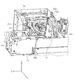
- FIG. 39 is a perspective view as seen from the right side of the cable arrangement for transmitting information from the ink container in the printer 66.
- FIG. 40 is an illustration showing transmission of information from the ink container in the printer 66. It is the figure which looked at the management of the cable which is carried out from the left side.
- FIG. 41 is an explanatory view showing the arrangement of a cable for transmitting information of black ink in the ink relay portion
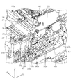
- FIG. 42 is a perspective view showing the arrangement of the cable in the structure
- FIG. 43 is a vicinity of the control portion in the structure
- FIG. 44 is a perspective view showing the cable routing
- FIG. 44 is an enlarged view of an edge guide provided in the housing for protecting the ink tube
- FIG. 45 is a connection of the frame in the state where the edge guide is removed in the housing FIG.
- the X direction is the scanning direction of the recording head
- the Y direction is the depth direction and paper conveyance direction of the recording apparatus
- the Z direction is the distance (gap) between the recording head and the paper. It shows the changing direction, that is, the device height direction.
- the ⁇ Y direction is the front side of the device
- the + Y direction side is the rear side of the device.
- the printer 66 also has the ink container storage cases 16 and 18 on the outside of the housing 68, that is, the end on the + X axis direction side and the end on the ⁇ X axis direction side.
- the ink container storage cases 16 and 18 have the same configuration as that of the first embodiment, so the description thereof will be omitted.
- an ink relay portion 54 is provided in the structure 13.
- the ink relay portion 54 is provided with a plurality of connection portions 54 a for connecting an ink tube 56 which supplies the ink from the ink container 14 corresponding to each color of black, magenta, cyan and yellow.
- the color side ink supply path (ink container storage case 18 to ink relay portion 54) is omitted, and in FIG. 29, the mounting portion 50 in the black side ink supply path is omitted. Further, in FIG. 29, only one of the three attachment portions 50 respectively corresponding to the color ink is drawn.
- Ink tubes 56 corresponding to the respective colors of black, magenta, cyan, and yellow extend from the ink relay portion 54 toward the carriage 22.
- the plurality of ink tubes 56 between the ink relay 54 and the carriage 22 are aligned in parallel in the Y axis direction in FIGS. 28 and 29 and follow the movement of the carriage 22 in the X axis direction in FIGS. 28 and 29. Is configured as.
- the plurality of ink tubes 56 are arranged such that the curved portion of the ink tube 56 along with the movement of the carriage 22 is formed in the Z-axis direction.
- ink tubes 56a and 56b corresponding to color inks of respective colors are connected to corresponding connection portions 54a of the ink relay portion 54, respectively. Therefore, when the ink container 14 of each color is connected to the mounting portion 50 of the ink container storage case 16 or 18, the ink can be supplied to the recording head 24 through the ink relay portion 54 by the ink tubes 56a and 56b.
- an opening 34 is provided on the side surface on the + X axis direction side of the housing 68. Further, the opening 34 is provided at a position facing the opening 32 of the ink container storage case 16 as in the first embodiment.
- the ink tube 56 a connected to the ink supply port 50 b provided in the ink container storage case 16 is led into the housing 68 through the opening 32 and the opening 34.
- the ink tube 56 a led into the housing 68 is connected to the corresponding connection portion 54 a of the ink relay portion 54.
- mounting portions 50 corresponding to the ink containers 14 of each color of magenta, cyan and yellow are provided.
- An ink tube 56b extends from the ink supply port 50b of each mounting portion 50 to an opening 32 provided in the ink container storage case 18 and an opening 34 disposed on the -X axial direction side of the housing 68. . Also in the present embodiment, the opening 34 and the opening 32 face each other.
- the ink tube 56b extending from the opening 34 into the housing 68 passes through the positioning member 70 provided at the end in the -X axial direction in the structure 13, and then the edge guide Go through 72.
- Each ink tube 56b that has passed through the edge guide 72 extends from the -X-axis direction to the + X-axis direction on the upper surface of the frame 60 extending in the X-axis direction on the -Y-axis direction side (front side) of the structure 13. .
- the edge guide 72 will be described.
- the frame 60 (see FIGS. 36 and 42) extending in the X-axis direction is fastened after being positioned by the positioning portion 78 at the end of the structure 13 on the -X-axis direction side. It is attached to the end of the structure 13 in the -X axial direction by the member 80.
- the edge guide 72 is attached so as to cover the edge 13 a and the edge of the end face 60 a of the frame 60 at the end on the ⁇ X axis direction side of the structure 13.
- the positioning portion 78 and the fastening member 80 are also covered by attaching the edge guide 72 to the end of the structure 13 on the ⁇ X axis direction side.
- the ink tube 56b extends in the + X axis direction on the frame 60 through the inside of the edge guide 72, so that the ink tube 56b can be prevented from coming into direct contact with these members and the edge. The risk of breakage of the tube 56b can be reduced.
- the ink tube 56b extending on the frame 60 on the + X axis direction side is on the frame 60 by the slider member 74 disposed on the ⁇ X axis direction side of the ink relay portion 54. It is bent in the + Z-axis direction and is connected to the corresponding connection portion 54a of the ink relay portion 54, respectively.
- the slider member 74 is a member for guiding the ink tube 56b from the frame 60 to the ink relay portion 54 while maintaining the minimum curvature so that the ink flow path of the ink tube 56b is not crushed.
- connection portion 50a corresponding to the black ink of the ink container storage case 16 (not shown for the sake of description in FIGS. 24 and 25).
- the flat cable 30 a is connected to a relay board 36 a disposed in the structure 13.
- a 15-core flat cable 40 a extends from the relay substrate 36 a toward the junction substrate 42 and is connected to the junction substrate 42.
- the nine-core flat cable 30b connected to each connection portion 50a corresponding to the color ink of the ink container storage case 18 (not shown for convenience of explanation in FIG. 24 and FIG. 25) It is connected to a relay board 36 b disposed in the housing storage case 18.
- a 15-core flat cable 40 b extends from the relay substrate 36 b toward the joining substrate 42 provided in the structural body 13 and is connected to the joining substrate 42. In FIGS. 39 and 40, only one of the three attachment portions 50 corresponding to color ink is drawn.
- One flat cable 40 extends from the junction board 42 toward the control unit 20. That is, the junction board 42 and the control unit 20 are connected by one flat cable 40.
- a nine-core flat cable 30a electrically connected to the CSIC substrate of the ink container containing the black ink through the connection portion 50a from the inside of the ink container storage case 16 through the opening 32 and the opening 34 and the inside of the housing 68 It extends to The flat cable 30 a is wired along the conductive member 64 in the ink container storage case 16.
- the ink relay portion 54 located at the end of the structure 13 in the + X axis direction side is a cover 76 which covers three directions of + X axis direction, ⁇ X axis direction and + Z axis direction. Is provided.
- the cover 76 is formed of a conductive material.
- the flat cable 30a drawn into the structure 13 extends along the inner wall on the + X axial direction side and the inner wall on the + Z axial direction side of the cover 76, and is provided on the outer wall on the ⁇ X axial direction side of the cover 76 Connected to 36a.
- the flat cable 30a transmits an analog signal and a digital signal from the CSIC substrate 28 to the relay substrate 36a.
- the analog signal is converted to a digital signal at the relay board 36a.
- a 15-core flat cable 40a extends in the + Y axis direction.
- the flat cable 40a is located on the + Y-axis direction side of the carriage 22 and changes its direction at the top of the frame extending in the X-axis direction and extends to the ⁇ X-axis direction side, and provided at the top of the frame Connected to the junction board 42.
- one end of a nine-core flat cable 30b is connected to the connection portion 50a of the attachment portion 50 corresponding to each color (magenta, cyan, yellow) in the ink container storage case 18, respectively.
- the other end is connected to the relay substrate 36 b disposed in the ink container storage case 18. That is, the plurality of flat cables 30b are connected to the relay board 36b.
- FIG. 35 only one of the three attachment portions 50 corresponding to color ink is drawn.
- the flat cable 30b corresponding to the color ink of each color transmits an analog signal and a digital signal from the connection portion 50a to the relay board 36b. Also in the relay substrate 36b disposed in the ink container storage case 18, the analog signal is converted to a digital signal.
- a conductive member 64 extending in the Y-axis direction is disposed.
- flat cables 30b extending from the connection portions 50a corresponding to the magenta and cyan color inks to the relay substrate 36 are wired in parallel without overlapping. Therefore, the plurality of flat cables 30b are not affected by noise from each other, or the effects of noise can be reduced.
- the relay substrate 36 b is fixed in the vicinity of the opening 32. Then, a 15-core flat cable 40 b is led from the relay board 36 b into the structure 13 through the opening 32 and the opening 34.
- the flat cable 30 b and the flat cable 40 b are detachably attached to the relay substrate 36 b by the connector 38.
- a 15-core flat cable 40 b extends from the relay substrate 36 b into the structure 13 through the opening 32 and the opening 34. As shown in FIGS. 36 and 43, the flat cable 40b extends in the + Z-axis direction at the end of the structure 13 on the -X-axis direction. The flat cable 40 b extends along the frame in the structure 13 to the joining substrate 42 and is connected to the joining substrate 42.
- the flat cable 40a extending from the relay substrate 36a provided in the structure 13 and the relay substrate provided in the ink container storage case 18 It joins with the flat cable 40b extended from 36b. That is, the two flat cables 40 a and 40 b are electrically combined into one flat cable 40 in the merging substrate 42. Then, one flat cable 40 extending from the merging substrate 42 is connected to the control unit 20 provided at the end on the ⁇ X axis direction side in the structure 13.
- open / close detection sensors 44, 44 are provided in the ink container storage cases 16, 18, respectively.
- the open / close detection sensor 44 and the control unit 20 are electrically connected by a cable 46. Therefore, the detection signal of the open / close detection sensor 44 is transmitted to the control unit 20, and the control unit 20 controls the recording operation based on the detection signal.
- the cable 46 extending from the open / close detection sensor 44 is routed around the inside of the structural body 13 from the ink container storage cases 16 and 18 and directly connected to the control unit 20.
- the cable 46 may be configured by two cables of the control unit side cable and the case side cable, and may be configured to be detachable at the connection unit.
- the connection portion can be disposed in the vicinity of the openings 32 and 34.
- the connection portion can be configured to connect these two cables by a relay board, a connector, or the like. With this configuration, the workability at the time of removing the ink container storage cases 16 and 18 from the apparatus main body 12 can be improved.
- the ink containers 14 contained in the ink container storage cases 16 and 18 can be replaced when the covers 19 and 19 of the ink container storage cases 16 and 18 are opened.
- the ink container 14 is accommodated in the ink container storage cases 16 and 18 when the covers 19 and 19 of the ink container storage cases 16 and 18 are opened.
- the ink may be replenished to the
- the printer 10 or 66 includes the recording head 24 capable of ejecting ink to the medium, the control unit 20 for controlling the recording head 24, the recording head 24 and the control unit 20. 13, an ink container attached to the outside of the case 26, 68 for containing the ink container 14 for containing ink, and a CSIC substrate 28 for holding information of the ink container 14 It comprises storage cases 16 and 18, ink tubes 56a and 56b for guiding the ink from the ink container 14 to the inside of the casings 26 and 68, and electrical wiring 29 for electrically connecting the control unit 20 and the CSIC substrate 28. ing.
- the electric wiring 29 includes relay boards 36a and 36b for connecting the flat cables 30a, 30b, 40a and 40b, flat cables 40a and 40b for forming wiring on the control unit 20 side with respect to the relay boards 36a and 36b, and the relay boards 36a. , 36b, and flat cables 30a, 30b that constitute the wiring on the CSIC substrate 28 side.
- the flat cables 40a and 40b and / or the flat cables 30a and 30b can be connected and disconnected at the relay boards 36a and 36b.
- the ink container storage cases 16 and 18 are formed with an opening 32 through which the flat cables 30a and 30b pass.
- the relay substrate 36 b is provided between the opening 32 and the CSIC substrate 28.
- the printer 10, 66 in the present embodiment is a case 26 that covers the recording head 24 capable of ejecting ink to the medium, a control unit 20 that controls the recording head 24, the recording head 24 and the control unit 20.
- 68 an ink container 14 for containing ink, and a CSIC substrate 28 for holding information of the ink container 14, the ink container storage cases 16, 18 attached to the outside of the housings 26, 68 and
- the ink tubes 56a and 56b for guiding the ink from the ink container 14 to the inside of the housings 26 and 68, and the electric wiring 29 for electrically connecting the control unit 20 and the CSIC substrate 28 are provided.
- the electric wiring 29 includes relay boards 36a and 36b for connecting the flat cables 30a, 30b, 40a and 40b, flat cables 40a and 40b for forming wiring on the control unit 20 side with respect to the relay boards 36a and 36b, and the relay boards 36a. , 36b, and flat cables 30a, 30b that constitute the wiring on the CSIC substrate 28 side.
- the flat cables 40a and 40b and / or the flat cables 30a and 30b can be connected and disconnected at the relay boards 36a and 36b.
- the housings 26, 68 have openings 34 through which the flat cables 30a, 30b pass.
- the relay substrate 36 a is provided between the opening 34 and the control unit 20.
- the relay boards 36a and 36b are configured by circuit boards. Further, the printers 10 and 66 include a plurality of ink containers 14 inside the ink container storage case 18. The CSIC substrate 28 and the flat cable 30 b are provided for each of the plurality of ink containers 14. The relay board 36b can connect a plurality of flat cables 30b and one flat cable 40b, and relays transmission and reception of information between the plurality of CSIC boards 28 and the control unit 20 using the one flat cable 40. Do.
- the relay substrate 36 b is fixed to the inside of the opening 32.
- the plurality of flat cables 30 b are wired in parallel without overlapping in the inside of the ink container storage case 18.
- the relay boards 36 a and 36 b are configured by the connector 38.
- the flat cables 30, 40, the relay substrate 36 and the joining substrate 42 according to the present invention are applied to an ink jet printer as an example of a recording apparatus, but the present invention is also applicable to other liquid ejecting apparatuses in general.
- an ink jet recording head is used as the liquid ejecting apparatus, and the recording apparatus is not limited to a recording apparatus such as a copier, a facsimile machine, etc., which ejects ink from the recording head to perform recording on a recording medium.
- the apparatus includes an apparatus which ejects a liquid corresponding to the application from a liquid jet head corresponding to the ink jet recording head to a jet receiving medium corresponding to a recording medium, and causes the liquid to adhere to the jet medium.
- a color material jet head used for manufacturing a color filter such as a liquid crystal display, an electrode material (conductive paste) used for forming an electrode such as an organic EL display or a surface emission display (FED)
- a jet head, a bioorganic jet head used for producing a biochip, a sample jet head as a precision pipette, and the like can be mentioned.
Landscapes
- Ink Jet (AREA)
- Accessory Devices And Overall Control Thereof (AREA)
Abstract
Priority Applications (4)
| Application Number | Priority Date | Filing Date | Title |
|---|---|---|---|
| US15/123,617 US9764557B2 (en) | 2014-03-14 | 2015-02-25 | Recording apparatus |
| JP2016507331A JP6150006B2 (ja) | 2014-03-14 | 2015-02-25 | 記録装置 |
| CN201580012309.5A CN106068187B (zh) | 2014-03-14 | 2015-02-25 | 记录装置 |
| EP15762123.6A EP3118001B1 (fr) | 2014-03-14 | 2015-02-25 | Appareil d'enregistrement |
Applications Claiming Priority (2)
| Application Number | Priority Date | Filing Date | Title |
|---|---|---|---|
| JP2014050941 | 2014-03-14 | ||
| JP2014-050941 | 2014-03-14 |
Publications (1)
| Publication Number | Publication Date |
|---|---|
| WO2015136868A1 true WO2015136868A1 (fr) | 2015-09-17 |
Family
ID=54071328
Family Applications (1)
| Application Number | Title | Priority Date | Filing Date |
|---|---|---|---|
| PCT/JP2015/000970 Ceased WO2015136868A1 (fr) | 2014-03-14 | 2015-02-25 | Appareil d'enregistrement |
Country Status (6)
| Country | Link |
|---|---|
| US (1) | US9764557B2 (fr) |
| EP (1) | EP3118001B1 (fr) |
| JP (1) | JP6150006B2 (fr) |
| CN (1) | CN106068187B (fr) |
| TW (1) | TWI648173B (fr) |
| WO (1) | WO2015136868A1 (fr) |
Cited By (2)
| Publication number | Priority date | Publication date | Assignee | Title |
|---|---|---|---|---|
| US10046568B2 (en) | 2016-01-14 | 2018-08-14 | Seiko Epson Corporation | Recording apparatus |
| US10682859B2 (en) | 2016-01-29 | 2020-06-16 | Seiko Epson Corporation | Multifunction peripheral |
Citations (3)
| Publication number | Priority date | Publication date | Assignee | Title |
|---|---|---|---|---|
| JP2003048332A (ja) * | 1998-11-26 | 2003-02-18 | Seiko Epson Corp | 印刷装置およびカートリッジ |
| JP2007331254A (ja) * | 2006-06-15 | 2007-12-27 | Canon Inc | 記録装置 |
| JP2013226729A (ja) * | 2012-04-26 | 2013-11-07 | Seiko Epson Corp | 記録装置 |
Family Cites Families (12)
| Publication number | Priority date | Publication date | Assignee | Title |
|---|---|---|---|---|
| MY138001A (en) * | 1998-11-02 | 2009-04-30 | Seiko Epson Corp | Ink cartridge and printer using the same |
| JP2000218818A (ja) * | 1998-11-26 | 2000-08-08 | Seiko Epson Corp | インク容器およびそれを用いる印刷装置 |
| EP1338931B1 (fr) * | 2002-02-19 | 2008-04-09 | Seiko Epson Corporation | Connecteur, unité de développement et appareil de formation d'images |
| JP4431961B2 (ja) * | 2004-03-05 | 2010-03-17 | ブラザー工業株式会社 | 画像記録装置 |
| JP4187007B2 (ja) * | 2006-04-28 | 2008-11-26 | ブラザー工業株式会社 | 画像記録装置 |
| CN200992020Y (zh) * | 2006-12-29 | 2007-12-19 | 文明华 | 一种墨水瓶装置 |
| KR100885062B1 (ko) * | 2007-08-30 | 2009-02-25 | 한국몰렉스 주식회사 | 프린터 잉크 카트리지용 전기 커넥터 |
| CN201136337Y (zh) * | 2007-12-18 | 2008-10-22 | 文明华 | 一种集中供墨装置 |
| JP2009202346A (ja) | 2008-02-26 | 2009-09-10 | Mimaki Engineering Co Ltd | プリンタシステムおよび外部インク供給装置 |
| JP5621363B2 (ja) * | 2010-07-07 | 2014-11-12 | セイコーエプソン株式会社 | 液体噴射ヘッドユニット、液体噴射ヘッドユニットの製造方法、及び、液体噴射装置 |
| JP5821196B2 (ja) * | 2011-01-26 | 2015-11-24 | セイコーエプソン株式会社 | インクジェット記録装置 |
| KR101550769B1 (ko) * | 2011-02-28 | 2015-09-07 | 세이코 엡슨 가부시키가이샤 | 기록 장치 |
-
2015
- 2015-02-25 WO PCT/JP2015/000970 patent/WO2015136868A1/fr not_active Ceased
- 2015-02-25 EP EP15762123.6A patent/EP3118001B1/fr active Active
- 2015-02-25 CN CN201580012309.5A patent/CN106068187B/zh active Active
- 2015-02-25 US US15/123,617 patent/US9764557B2/en active Active
- 2015-02-25 JP JP2016507331A patent/JP6150006B2/ja active Active
- 2015-03-11 TW TW104107811A patent/TWI648173B/zh active
Patent Citations (3)
| Publication number | Priority date | Publication date | Assignee | Title |
|---|---|---|---|---|
| JP2003048332A (ja) * | 1998-11-26 | 2003-02-18 | Seiko Epson Corp | 印刷装置およびカートリッジ |
| JP2007331254A (ja) * | 2006-06-15 | 2007-12-27 | Canon Inc | 記録装置 |
| JP2013226729A (ja) * | 2012-04-26 | 2013-11-07 | Seiko Epson Corp | 記録装置 |
Cited By (2)
| Publication number | Priority date | Publication date | Assignee | Title |
|---|---|---|---|---|
| US10046568B2 (en) | 2016-01-14 | 2018-08-14 | Seiko Epson Corporation | Recording apparatus |
| US10682859B2 (en) | 2016-01-29 | 2020-06-16 | Seiko Epson Corporation | Multifunction peripheral |
Also Published As
| Publication number | Publication date |
|---|---|
| EP3118001A4 (fr) | 2017-10-25 |
| US9764557B2 (en) | 2017-09-19 |
| CN106068187A (zh) | 2016-11-02 |
| TW201538345A (zh) | 2015-10-16 |
| EP3118001B1 (fr) | 2020-09-02 |
| US20170087859A1 (en) | 2017-03-30 |
| JPWO2015136868A1 (ja) | 2017-04-06 |
| JP6150006B2 (ja) | 2017-06-21 |
| CN106068187B (zh) | 2017-07-28 |
| EP3118001A1 (fr) | 2017-01-18 |
| TWI648173B (zh) | 2019-01-21 |
Similar Documents
| Publication | Publication Date | Title |
|---|---|---|
| JP6065571B2 (ja) | 画像記録装置 | |
| JP6651856B2 (ja) | 液体消費装置およびその組立方法 | |
| JP2016144951A (ja) | インクジェット記録装置 | |
| JP6150006B2 (ja) | 記録装置 | |
| JP6150007B2 (ja) | 記録装置 | |
| CN202656615U (zh) | 喷墨式记录装置 | |
| JP5807543B2 (ja) | 液体噴射装置及び液体噴射ヘッドに接続された配線部材の支持方法 | |
| JP5156600B2 (ja) | 電線保護構造及びこれを備えた画像形成装置 | |
| JP6035839B2 (ja) | 記録装置 | |
| JP2013154573A (ja) | 記録装置 | |
| JP2019014242A (ja) | 液体吐出ヘッドユニット及び液体吐出装置 | |
| US10183512B2 (en) | Recording apparatus | |
| US12589604B2 (en) | Liquid ejection head, method of detaching protection member from liquid ejection head, and liquid ejection apparatus | |
| JP2013226658A (ja) | 記録装置 | |
| JP2018130937A (ja) | キャリッジ装置及びプリント装置 | |
| JP6291928B2 (ja) | 記録装置 | |
| JP6003721B2 (ja) | 液体吐出装置 | |
| JP2018069514A (ja) | 液体噴射装置 | |
| JP6288421B2 (ja) | 記録装置 | |
| JP5927971B2 (ja) | インクジェット記録装置 | |
| JP2017121714A (ja) | 記録装置、制御ユニット | |
| JP2013166302A (ja) | インクジェット記録装置 | |
| JP2017064994A (ja) | プリント装置、キャリッジ装置及びフレキシブルサポート | |
| JP2014140987A (ja) | インクジェット記録装置 |
Legal Events
| Date | Code | Title | Description |
|---|---|---|---|
| 121 | Ep: the epo has been informed by wipo that ep was designated in this application |
Ref document number: 15762123 Country of ref document: EP Kind code of ref document: A1 |
|
| ENP | Entry into the national phase |
Ref document number: 2016507331 Country of ref document: JP Kind code of ref document: A |
|
| WWE | Wipo information: entry into national phase |
Ref document number: 15123617 Country of ref document: US |
|
| NENP | Non-entry into the national phase |
Ref country code: DE |
|
| REEP | Request for entry into the european phase |
Ref document number: 2015762123 Country of ref document: EP |
|
| WWE | Wipo information: entry into national phase |
Ref document number: 2015762123 Country of ref document: EP |