WO2015136896A1 - Appareil de génération d'hydrogène, procédé de commande associé et système de pile à combustible - Google Patents
Appareil de génération d'hydrogène, procédé de commande associé et système de pile à combustible Download PDFInfo
- Publication number
- WO2015136896A1 WO2015136896A1 PCT/JP2015/001180 JP2015001180W WO2015136896A1 WO 2015136896 A1 WO2015136896 A1 WO 2015136896A1 JP 2015001180 W JP2015001180 W JP 2015001180W WO 2015136896 A1 WO2015136896 A1 WO 2015136896A1
- Authority
- WO
- WIPO (PCT)
- Prior art keywords
- reformer
- power
- raw material
- power source
- temperature
- Prior art date
- Legal status (The legal status is an assumption and is not a legal conclusion. Google has not performed a legal analysis and makes no representation as to the accuracy of the status listed.)
- Ceased
Links
Images


Classifications
-
- C—CHEMISTRY; METALLURGY
- C01—INORGANIC CHEMISTRY
- C01B—NON-METALLIC ELEMENTS; COMPOUNDS THEREOF; METALLOIDS OR COMPOUNDS THEREOF NOT COVERED BY SUBCLASS C01C
- C01B3/00—Hydrogen; Gaseous mixtures containing hydrogen; Separation of hydrogen from mixtures containing it; Purification of hydrogen; Reversible storage of hydrogen
- C01B3/02—Production of hydrogen; Production of gaseous mixtures containing hydrogen
- C01B3/32—Production of hydrogen; Production of gaseous mixtures containing hydrogen by reaction of gaseous or liquid organic compounds with gasifying agents, e.g. water, carbon dioxide or air
- C01B3/34—Production of hydrogen; Production of gaseous mixtures containing hydrogen by reaction of gaseous or liquid organic compounds with gasifying agents, e.g. water, carbon dioxide or air by reaction of hydrocarbons with gasifying agents
- C01B3/38—Production of hydrogen; Production of gaseous mixtures containing hydrogen by reaction of gaseous or liquid organic compounds with gasifying agents, e.g. water, carbon dioxide or air by reaction of hydrocarbons with gasifying agents using catalysts
- C01B3/384—Production of hydrogen; Production of gaseous mixtures containing hydrogen by reaction of gaseous or liquid organic compounds with gasifying agents, e.g. water, carbon dioxide or air by reaction of hydrocarbons with gasifying agents using catalysts with external heating of the catalyst
-
- H—ELECTRICITY
- H01—ELECTRIC ELEMENTS
- H01M—PROCESSES OR MEANS, e.g. BATTERIES, FOR THE DIRECT CONVERSION OF CHEMICAL ENERGY INTO ELECTRICAL ENERGY
- H01M8/00—Fuel cells; Manufacture thereof
- H01M8/04—Auxiliary arrangements, e.g. for control of pressure or for circulation of fluids
- H01M8/04223—Auxiliary arrangements, e.g. for control of pressure or for circulation of fluids during start-up or shut-down; Depolarisation or activation, e.g. purging; Means for short-circuiting defective fuel cells
- H01M8/04225—Auxiliary arrangements, e.g. for control of pressure or for circulation of fluids during start-up or shut-down; Depolarisation or activation, e.g. purging; Means for short-circuiting defective fuel cells during start-up
-
- H—ELECTRICITY
- H01—ELECTRIC ELEMENTS
- H01M—PROCESSES OR MEANS, e.g. BATTERIES, FOR THE DIRECT CONVERSION OF CHEMICAL ENERGY INTO ELECTRICAL ENERGY
- H01M8/00—Fuel cells; Manufacture thereof
- H01M8/04—Auxiliary arrangements, e.g. for control of pressure or for circulation of fluids
- H01M8/04298—Processes for controlling fuel cells or fuel cell systems
- H01M8/043—Processes for controlling fuel cells or fuel cell systems applied during specific periods
- H01M8/04302—Processes for controlling fuel cells or fuel cell systems applied during specific periods applied during start-up
-
- H—ELECTRICITY
- H01—ELECTRIC ELEMENTS
- H01M—PROCESSES OR MEANS, e.g. BATTERIES, FOR THE DIRECT CONVERSION OF CHEMICAL ENERGY INTO ELECTRICAL ENERGY
- H01M8/00—Fuel cells; Manufacture thereof
- H01M8/06—Combination of fuel cells with means for production of reactants or for treatment of residues
- H01M8/0606—Combination of fuel cells with means for production of reactants or for treatment of residues with means for production of gaseous reactants
- H01M8/0612—Combination of fuel cells with means for production of reactants or for treatment of residues with means for production of gaseous reactants from carbon-containing material
- H01M8/0618—Reforming processes, e.g. autothermal, partial oxidation or steam reforming
-
- C—CHEMISTRY; METALLURGY
- C01—INORGANIC CHEMISTRY
- C01B—NON-METALLIC ELEMENTS; COMPOUNDS THEREOF; METALLOIDS OR COMPOUNDS THEREOF NOT COVERED BY SUBCLASS C01C
- C01B2203/00—Integrated processes for the production of hydrogen or synthesis gas
- C01B2203/02—Processes for making hydrogen or synthesis gas
- C01B2203/0205—Processes for making hydrogen or synthesis gas containing a reforming step
- C01B2203/0227—Processes for making hydrogen or synthesis gas containing a reforming step containing a catalytic reforming step
- C01B2203/0233—Processes for making hydrogen or synthesis gas containing a reforming step containing a catalytic reforming step the reforming step being a steam reforming step
-
- C—CHEMISTRY; METALLURGY
- C01—INORGANIC CHEMISTRY
- C01B—NON-METALLIC ELEMENTS; COMPOUNDS THEREOF; METALLOIDS OR COMPOUNDS THEREOF NOT COVERED BY SUBCLASS C01C
- C01B2203/00—Integrated processes for the production of hydrogen or synthesis gas
- C01B2203/04—Integrated processes for the production of hydrogen or synthesis gas containing a purification step for the hydrogen or the synthesis gas
- C01B2203/0435—Catalytic purification
- C01B2203/044—Selective oxidation of carbon monoxide
-
- C—CHEMISTRY; METALLURGY
- C01—INORGANIC CHEMISTRY
- C01B—NON-METALLIC ELEMENTS; COMPOUNDS THEREOF; METALLOIDS OR COMPOUNDS THEREOF NOT COVERED BY SUBCLASS C01C
- C01B2203/00—Integrated processes for the production of hydrogen or synthesis gas
- C01B2203/04—Integrated processes for the production of hydrogen or synthesis gas containing a purification step for the hydrogen or the synthesis gas
- C01B2203/0465—Composition of the impurity
- C01B2203/047—Composition of the impurity the impurity being carbon monoxide
-
- C—CHEMISTRY; METALLURGY
- C01—INORGANIC CHEMISTRY
- C01B—NON-METALLIC ELEMENTS; COMPOUNDS THEREOF; METALLOIDS OR COMPOUNDS THEREOF NOT COVERED BY SUBCLASS C01C
- C01B2203/00—Integrated processes for the production of hydrogen or synthesis gas
- C01B2203/06—Integration with other chemical processes
- C01B2203/066—Integration with other chemical processes with fuel cells
-
- C—CHEMISTRY; METALLURGY
- C01—INORGANIC CHEMISTRY
- C01B—NON-METALLIC ELEMENTS; COMPOUNDS THEREOF; METALLOIDS OR COMPOUNDS THEREOF NOT COVERED BY SUBCLASS C01C
- C01B2203/00—Integrated processes for the production of hydrogen or synthesis gas
- C01B2203/08—Methods of heating or cooling
- C01B2203/0805—Methods of heating the process for making hydrogen or synthesis gas
- C01B2203/0811—Methods of heating the process for making hydrogen or synthesis gas by combustion of fuel
-
- C—CHEMISTRY; METALLURGY
- C01—INORGANIC CHEMISTRY
- C01B—NON-METALLIC ELEMENTS; COMPOUNDS THEREOF; METALLOIDS OR COMPOUNDS THEREOF NOT COVERED BY SUBCLASS C01C
- C01B2203/00—Integrated processes for the production of hydrogen or synthesis gas
- C01B2203/16—Controlling the process
- C01B2203/1604—Starting up the process
-
- Y—GENERAL TAGGING OF NEW TECHNOLOGICAL DEVELOPMENTS; GENERAL TAGGING OF CROSS-SECTIONAL TECHNOLOGIES SPANNING OVER SEVERAL SECTIONS OF THE IPC; TECHNICAL SUBJECTS COVERED BY FORMER USPC CROSS-REFERENCE ART COLLECTIONS [XRACs] AND DIGESTS
- Y02—TECHNOLOGIES OR APPLICATIONS FOR MITIGATION OR ADAPTATION AGAINST CLIMATE CHANGE
- Y02E—REDUCTION OF GREENHOUSE GAS [GHG] EMISSIONS, RELATED TO ENERGY GENERATION, TRANSMISSION OR DISTRIBUTION
- Y02E60/00—Enabling technologies; Technologies with a potential or indirect contribution to GHG emissions mitigation
- Y02E60/30—Hydrogen technology
- Y02E60/50—Fuel cells
Definitions
- the present invention relates to a hydrogen generator, an operation method thereof, and a fuel cell system. More specifically, the present invention relates to a hydrogen generator having an activation mode that reduces power consumption when activation power is supplied from a self-sustained activation power source, an operation method thereof, and a fuel cell system.
- fuel cell system a fuel cell cogeneration system that has both high power generation efficiency and high overall efficiency has attracted attention as a distributed power generation device that can effectively use energy. .
- This fuel cell system includes a fuel cell as the main body of the power generation unit.
- a fuel cell for example, a phosphoric acid fuel cell, a molten carbonate fuel cell, an alkaline aqueous fuel cell, a solid polymer fuel cell, a solid electrolyte fuel cell, or the like is used.
- a phosphoric acid fuel cell and a polymer electrolyte fuel cell (abbreviated as “PEFC”) have a relatively low operating temperature during a power generation operation. Therefore, the fuel cells constituting the fuel cell system Is preferably used.
- the polymer electrolyte fuel cell is particularly suitable for applications such as portable electronic devices and electric vehicles because the deterioration of the electrode catalyst is less than that of the phosphoric acid fuel cell and the electrolyte does not dissipate. Used for.
- fuel cells for example, phosphoric acid fuel cells and polymer electrolyte fuel cells
- hydrogen is used as a fuel during power generation operation.
- the means for supplying hydrogen necessary for power generation operation in these fuel cells is not usually provided as an infrastructure.
- a reforming reaction is generally used as a method for generating hydrogen to be supplied to a fuel cell.
- the reforming reaction includes, for example, hydrogen as a main component by reacting raw material city gas and water vapor at a high temperature of about 600 ° C. to 700 ° C. using a Ni-based or Ru-based reforming catalyst. It is a reaction that generates a hydrogen-containing gas.
- the heat energy required for the reforming reaction is generally obtained by burning fuel off-gas from the fuel cell with a burner.
- it also has an electric heater that heats the hydrogen generator, and at the time of start-up, a burner is activated and the electric heater is activated using the power of the system power supply to propose a configuration that raises the temperature of the hydrogen generator (For example, refer to Patent Document 1).
- the self-sustained start-up power supply (storage battery or the like)
- the self-sustained start-up power supply (storage battery or the like)
- the present invention has been made in view of the above-described problems, and suppresses power consumption when starting by supplying power from a self-starting power source.
- the hydrogen generator of the present invention includes a reformer that reforms a hydrocarbon-containing raw material to generate a hydrogen-containing gas, a raw material supplier that supplies the raw material to the reformer, and at least one of the raw material and the hydrogen-containing gas
- a combustor that heats the reformer, combustion air supplier that supplies combustion air to the combustor, and a self-starting power source that supplies power to at least the raw material supplier and the combustion air supplier It has.
- a special power supply that is not supplied with power from the first power source is started by supplying power from at least a first power source other than the self-starting power source to an auxiliary machine including a raw material supplier and a combustion air supplier.
- a controller configured to control the first heating amount burned by the combustor at the time of special startup to be larger than the second heating amount burned by the combustor at the normal startup time is provided.
- the amount of heat input to the hydrogen generator is increased at the time of special startup, so the rate of temperature increase to the appropriate temperature of the catalyst is increased, and the power supply time from the self-starting power supply to the auxiliary machine
- the power supply amount can be reduced, and the self-starting power supply can be reduced in size.
- the temperature of the catalyst can be raised earlier than in the prior art when starting by power supply from the self-starting power source, and the starting time Can be shortened. Therefore, the amount of power consumed by the auxiliary machine can be reduced, and the self-starting power supply can be reduced in size.
- FIG. 1 is a block diagram showing an example of a schematic configuration of the hydrogen generator according to the first embodiment of the present invention.
- FIG. 2 is a flowchart showing an example of the operation of the hydrogen generator according to the first embodiment of the present invention.
- FIG. 3 is a flowchart showing an example of a parameter changing operation at the time of special activation of the hydrogen generator according to the first embodiment of the present invention.
- FIG. 4 is a flowchart showing an example of a parameter changing operation at the time of special activation of the hydrogen generator according to the first modification of the first embodiment of the present invention.
- FIG. 5 is a flowchart showing an example of the parameter changing operation at the normal startup time of the hydrogen generator according to the first modification of the first embodiment of the present invention.
- FIG. 1 is a block diagram showing an example of a schematic configuration of the hydrogen generator according to the first embodiment of the present invention.
- FIG. 2 is a flowchart showing an example of the operation of the hydrogen generator according to the first embodiment of the present invention.
- FIG. 6 is a flowchart showing an example of a second modification of the parameter changing operation at the time of special activation of the hydrogen generator according to the first embodiment of the present invention.
- FIG. 7 is a flowchart showing an example of a second modification of the parameter changing operation at the normal startup time of the hydrogen generator according to the first embodiment of the present invention.
- FIG. 8 is a flowchart showing an example of a third modification of the parameter changing operation at the time of special activation of the hydrogen generator according to the first embodiment of the present invention.
- FIG. 9 is a flowchart showing an example of a fourth modification of the parameter changing operation at the time of special activation of the hydrogen generator according to the first embodiment of the present invention.
- FIG. 10 is a flowchart showing an example of the operation of the hydrogen generator according to the second embodiment of the present invention.
- FIG. 11 is a flowchart showing an example of a parameter changing operation at the time of special activation of the hydrogen generator according to the second embodiment of the present invention.
- FIG. 12 is a flowchart showing an example of a first modification of the parameter changing operation at the time of special activation of the hydrogen generator according to the second embodiment of the present invention.
- FIG. 13 is a flowchart which shows an example of operation
- FIG. 14 is a flowchart showing an example of a parameter changing operation at the time of special startup of the hydrogen generator according to the third embodiment of the present invention.
- FIG. 14 is a flowchart showing an example of a parameter changing operation at the time of special startup of the hydrogen generator according to the third embodiment of the present invention.
- FIG. 15 is a flowchart which shows an example of the 1st modification of the parameter change operation
- FIG. 16 is a flowchart which shows an example of the 2nd modification of the parameter change operation
- FIG. 17 is a flowchart showing an example of a third modification of the parameter changing operation at the time of special activation of the hydrogen generator according to the third embodiment of the present invention.
- FIG. 18 is a block diagram showing an example of a schematic configuration of a fuel cell system according to the fourth embodiment of the present invention.
- FIG. 19 is a flowchart showing an example of the operation of the fuel cell system according to the fourth embodiment of the present invention.
- FIG. 20 is a flowchart showing an example of a first modification of the operation of the fuel cell system according to the fourth embodiment of the present invention.
- FIG. 1 is a block diagram showing an example of a schematic configuration of a hydrogen generator 15 according to the first embodiment of the present invention.
- the hydrogen generator 15 of the present embodiment includes a reformer 1, a raw material supplier 2, a combustor 3, a combustion air supplier 4, and a self-starting power source 5. , Controller 6, water supplier 7, reformer temperature detector 8, CO reducer 9, CO reducer temperature detector 10, selective oxidizer 11, oxygen-containing gas supplier 12, And a selective oxidizer temperature detector 13.
- the reformer 1 generates a hydrogen-containing gas using the raw material gas. Specifically, in the reforming catalyst in the reformer 1, the raw material gas undergoes a reforming reaction to generate a hydrogen-containing gas. Any form may be sufficient as reforming reaction, for example, steam reforming reaction, autothermal reaction, partial oxidation reaction, etc. are used.
- the reforming reaction is a steam reforming reaction
- an evaporator that generates steam and a water supplier 7 that supplies water to the evaporator are provided.
- the hydrogen generator 15 is further provided with an air supply device that supplies air to the reformer 1.
- the raw material supplier 2 is a gas containing an organic compound composed of at least carbon and hydrogen, such as city gas, natural gas, or LPG mainly composed of methane. Supply it.
- the raw material supplier 2 may be equipped with a flow rate adjusting function for adjusting the raw material flow rate to a necessary flow rate as appropriate. Examples of the raw material supplier 2 include a pump.
- the combustor 3 burns the raw material gas, the hydrogen-containing gas or the raw material gas after the reformer 1, and heats the reformer 1, the CO reducer 9, and the selective oxidizer 11.
- the heating may be direct heating by a flame or indirect heating by combustion exhaust gas.
- the combustor 3 is arranged on the downstream side with respect to the reformer 1, but the present invention is not limited to this configuration, and the combustor 3 is modified by branching the raw material gas path.
- the mass device 1 may be arranged in parallel.
- An example of the combustor 3 is a burner.
- the combustion air supply unit 4 supplies combustion air necessary for burning the raw material gas or the hydrogen-containing gas after the reformer 1 to the combustor 3 in the combustor 3.
- Examples of the combustion air supply device 4 include a blower.
- the self-starting power source 5 supplies power to the auxiliary machines and starts the hydrogen generator 15.
- An example of the self-starting power supply 5 is a secondary battery.
- the first power source for example, a commercial power source (system power source), a solar cell, or the like can be used.
- power may be supplied from only the first power source to the auxiliary machine, or power may be supplied from the first power source and the independent startup power source 5 to the auxiliary machine.
- the power supply of the first power supply may be supplied to the auxiliary machine via the self-starting power supply 5.
- the controller 6 only needs to have a control function, and includes an arithmetic processing unit and a storage unit for storing a control program.
- Examples of the arithmetic processing unit include an MPU and a CPU.
- An example of the storage unit is a memory.
- the controller 6 may be composed of a single controller that performs centralized control, or may be composed of a plurality of controllers that perform distributed control in cooperation with each other.
- the water supplier 7 supplies water to the hydrogen generator 15.
- the supplied water is preferably in the state of water vapor. Therefore, the water supply downstream flow path 14 on the downstream side of the water supply 7 is heated by the combustor 3, the heater, or the combustion exhaust gas to generate water vapor.
- An example of the water supplier 7 is a water pump.
- the reformer temperature detector 8 detects the temperature of the reformer 1.
- the reformer temperature detector 8 is preferably configured to directly measure the catalyst temperature inside the reformer 1, but if the catalyst temperature can be estimated from the detected value, the reformer 1 outside the reformer 1 Alternatively, the temperature detection unit may be installed in the vicinity thereof. Examples of the reformer temperature detector 8 include a thermocouple and a thermistor.
- the CO reducer 9 reduces CO in the hydrogen-containing gas output from the reformer 1 by a shift reaction, an oxidation reaction, or a methanation reaction.
- the CO reducer temperature detector 10 detects the temperature of the CO reducer 9.
- the CO reducer temperature detector 10 is preferably configured to directly measure the catalyst temperature inside the CO reducer 9, but if the catalyst temperature can be estimated from the detected value, the CO reducer 9 external Alternatively, the temperature detection unit may be installed in the vicinity thereof.
- Examples of the CO reducer temperature detector 10 include a thermocouple and a thermistor.
- the selective oxidizer 11 further reduces carbon monoxide in the gas by an oxidation reaction.
- the outline of the selective oxidizer 11 is preferably made of a metal such as stainless steel, for example.
- the oxygen-containing gas supply device 12 supplies an oxygen-containing gas to the selective oxidizer 11, and examples thereof include a blower.
- the selective oxidizer temperature detector 13 detects the temperature of the selective oxidizer 11.
- the selective oxidizer temperature detector 13 is preferably configured to directly measure the catalyst temperature inside the selective oxidizer 11, but if the catalyst temperature can be estimated from the detected value, the selective oxidizer 11 outside the selective oxidizer 11 Alternatively, the temperature detection unit may be installed in the vicinity thereof. Examples of the selective oxidizer temperature detector 13 include a thermocouple and a thermistor.
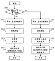
- FIG. 2 is a flowchart showing an example of the operation of the hydrogen generator 15 according to the first embodiment of the present invention.
- Step S000 Upon receipt of the start command, the controller 6 detects whether power is supplied from the first power supply or only from the self-starting power supply 5. When power is supplied from the first power source (S000, Yes), the process proceeds to step S001 of the normal startup operation, and when power is supplied only from the independent startup power source 5 (S000, No) The process proceeds to step S101 of the starting operation.
- Step S001 Power is supplied from the first power source to the raw material supply unit 2 and the combustion air supply unit 4 in accordance with a command from the controller 6 that detects that power is supplied from the first power source.
- the raw material gas is supplied so that the heating amount becomes the second heating amount (for example, 500 W).
- the heating amount is the amount of heat by which the raw material gas and combustion air are combusted in the combustor and the hydrogen generator is heated.
- Step S002 In the combustor 3, the raw material gas ignited by the ignition device is combusted together with the combustion air. Heat generated by combustion in the combustor 3 is supplied to the reformer 1, the CO reducer 9, and the selective oxidizer 11 to raise the temperature of the reformer 1, the CO reducer 9, and the selective oxidizer 11. At the same time, heating with a heater may be used in combination.
- Step S003 After the reformer temperature detector 8 detects that the temperature of the reformer 1 is the second temperature (for example, 200 ° C.), the water is supplied from the water supplier 7 to the second temperature.
- the reforming reaction is started at a flow rate (for example, 5 cc / min).
- a flow rate for example, 5 cc / min.
- the CO reducer temperature detector 10 and the selective oxidizer temperature detector 13 are present, either the CO reducer temperature detector 10 or the selective oxidizer temperature detector 13 is selected.
- a threshold value may be set in advance for the temperature measured by the above, and water supply may be started. In this case, for example, the threshold value can be 120 ° C. in the CO reducer temperature detector 10 and 110 ° C. in the selective oxidizer temperature detector 13.
- Step S004 When the selective oxidizer temperature detector 13 detects a predetermined temperature, for example, 100 ° C., the oxygen-containing gas is selected from the oxygen-containing gas supply device 12 at the eighth flow rate (for example, 0.6 l / min). The oxidizer 11 is supplied.
- a predetermined temperature for example, 100 ° C.
- the oxygen-containing gas is selected from the oxygen-containing gas supply device 12 at the eighth flow rate (for example, 0.6 l / min).
- the oxidizer 11 is supplied.
- Step S101 Power is supplied from the self-sustained startup power source 5 to the raw material supplier 2 and the combustion air supplier 4 in accordance with a command from the controller 6 that has detected that power is supplied from the self-sustained startup power source 5.
- the heating amount becomes a first heating amount (for example, 700 W) larger than the second heating amount (for example, 500 W).
- the source gas is supplied.
- the heating amount is the amount of heat by which the raw material gas and combustion air are combusted in the combustor and the hydrogen generator is heated.
- Step S102 In the combustor 3, the raw material gas ignited by the ignition device is combusted together with the combustion air, and the reformer 1 is heated by the flame, and at the same time, the CO reducer 9, the selective oxidizer 11, and the water.
- the feeder downstream flow path 14 is heated by heat exchange from the combustion exhaust gas. At the same time, heating with a heater may be used in combination.
- step S001 and step S002 source gas is supplied to the combustor 3 with a larger heating amount and burned.
- the heat generated by the combustion in the combustor 3 is supplied to the reformer 1, the CO reducer 9, the selective oxidizer 11, and the water supply downstream channel 14.
- the reformer 1, the CO reducer 9, and the selective oxidizer 11 are heated with a larger amount of heat than during normal startup, so that the temperature rise can be accelerated.
- Step S103 It is detected by the reformer temperature detector 8 that the temperature of the reformer 1 is equal to or higher than the second temperature (for example, 200 ° C.) or from the start of combustion of the combustor 3 After the second time (for example, 15 minutes) or more has elapsed, water is supplied from the water supplier 7 at a second flow rate (for example, 5 cc / min), and the reforming reaction starts.
- the second temperature for example, 200 ° C.
- water for example, 5 cc / min
- the CO reducer temperature detector 10 and the selective oxidizer temperature detector 13 When at least one of the CO reducer temperature detector 10 and the selective oxidizer temperature detector 13 exists, either the CO reducer temperature detector 10 or the selective oxidizer temperature detector 13 A threshold value may be set in advance for the temperature measured by the above, and water supply may be started. In this case, for example, the threshold value can be 120 ° C. in the CO reducer temperature detector 10 and 110 ° C. in the selective oxidizer temperature detector 13.
- Step S104 When the temperature of the selective oxidizer temperature detector 13 is detected to be a predetermined temperature of 100 ° C., or when a predetermined time (for example, 15 minutes) has elapsed from the start of combustion of the combustor 3.
- the oxygen-containing gas is supplied from the oxygen-containing gas supply device 12 to the selective oxidizer 11 at a seventh flow rate (for example, 0.7 l / min) higher than the eighth flow rate (for example, 0.6 l / min). .
- oxygen is supplied in an amount corresponding to the amount of carbon monoxide in the hydrogen-containing gas, and is controlled so as not to excessively oxidize the hydrogen. Since the oxygen-containing gas is increased with respect to the normal start-up, the oxidation reaction of hydrogen in the selective oxidizer 11 is promoted and the catalyst is heated by the reaction heat, so that the selective oxidizer 11 is compared with step S004. The temperature rises faster.
- the temperatures of the reformer 1, the CO reducer 9, and the selective oxidizer 11 of the hydrogen generator 15 are set to predetermined temperatures (for example, 550 ° C. in the reformer 1 and 250 ° C. in the CO reducer 9).
- the temperature reaches 160 ° C., and hydrogen is supplied from the hydrogen generator 15 to the hydrogen utilization device.
- the temperature of the hydrogen generator 15 can be increased at the time of special startup in which power is supplied only from the self-starting power supply 5 as compared to the normal startup in which power is supplied from the first power supply.
- the start-up of the hydrogen generator 15 can be accelerated, and the time for supplying power from the self-sustained startup power supply 5 to the auxiliary machine can be shortened, so that the self-sustained startup power supply 5 can be reduced in size. .
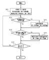
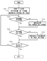
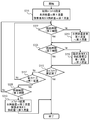
- FIG. 3 is a flowchart showing an example of a parameter changing operation at the time of special activation of the hydrogen generator 15 according to the first embodiment of the present invention.
- This flow determines the combustion amount and the supply amount of the oxygen-containing gas in accordance with the temperatures of the reformer 1 and the selective oxidizer 11 when the process proceeds to the special starting operation after step S101 shown in FIG. Is.
- the raw material gas supply amount from the raw material supply device 2 is the first heating amount (for example, 700 W), and the oxygen-containing gas supply amount of the oxygen-containing gas supply device 12 is the seventh flow rate (for example, 0). .7 l / min).
- Step S112 When the temperature of the reformer 1 becomes equal to or higher than the predetermined temperature (S112, NO), the process proceeds to Step S113. When this condition is not satisfied (S112, YES), the process proceeds to step S114.
- the predetermined temperature refers to a temperature at which the reformer 1 can start the steam reforming reaction, and is 250 ° C. or higher, preferably 350 ° C. or higher.
- Step S113 The controller 6 controls the heating amount burned in the combustor 3 to a third heating amount (for example, 400 W) smaller than the first heating amount (for example, 700 W).
- the third heating amount may be the same amount as the second heating amount (for example, 500 W).
- the period during which heating is continued with a higher heating amount than during normal startup can be limited, so that the temperature rise of the reformer 1 due to heating with a higher heating amount than during normal startup, and hydrogen Thermal damage due to overheating of the structure of the generation device 15, and further deterioration in performance due to a change in the heated portion caused by the flame length being different from that at the time of normal activation can be suppressed.
- Step S114 When the temperature of the selective oxidizer 11 becomes equal to or higher than the fifth temperature (for example, 150 ° C.) (S114, NO), the process proceeds to Step S115. When this condition is not satisfied (S114, YES), the process proceeds to step S116.
- the fifth temperature for example, 150 ° C.
- Step S115 The controller 6 sets the amount of oxygen-containing gas supplied from the oxygen-containing gas supplier 12 to a ninth flow rate (for example, 0.5 l / min) smaller than the seventh flow rate (for example, 0.7 l / min). min). Note that the ninth flow rate may be the same amount as the eighth flow rate (for example, 0.6 l / min).
- the temperature of the selective oxidizer 11 is sufficiently increased, the amount of the oxygen-containing gas supplied to the selective oxidizer 11 is reduced, so that the oxidation reaction of hydrogen in the hydrogen-containing gas on the selective oxidation catalyst is suppressed.
- reduction of hydrogen due to oxidation reaction can be reduced.
- the hydrogen concentration in the hydrogen-containing gas increases, the amount of hydrogen supplied to the hydrogen-using device can be increased, and at the same time, the overheating of the selective oxidizer 11 due to the oxidation reaction can be prevented.
- Step S116 The controller 6 determines whether or not all parameters have been changed from the initial state. If changed (S116, YES), the controller 6 proceeds to the end step, and if not changed (S116, NO), S112. Migrate to
- the hydrogen generator 15 in the first embodiment can be operated from the first power source at the time of special startup in which power is supplied only from the self-starting power source 5.
- the temperature of the hydrogen generator 15 can be increased as compared with the normal startup time when power is supplied. And the thermal damage of the structure by the heating amount increase and the fall of the hydrogen concentration in hydrogen containing gas can be suppressed.
- the start-up of the hydrogen generator 15 can be accelerated, and the time for supplying power from the self-starting power supply 5 to the auxiliary machine can be shortened, so that the self-starting power supply 5 can be reduced in size.
- the configuration of the hydrogen generator 15 according to the first modification of the first embodiment of the present invention is the same as the hydrogen generator 15 of the first embodiment shown in FIG. That is, the reformer 1, the raw material supplier 2, the combustor 3, the combustion air supplier 4, the self-starting power source 5, the controller 6, the water supplier 7, and the reformer temperature detection.
- the apparatus 8 includes a CO reducer 9, a CO reducer temperature detector 10, a selective oxidizer 11, an oxygen-containing gas supply device 12, and a selective oxidizer temperature detector 13. Then, when power is supplied from the first power source at the time of special activation, the operation proceeds to normal activation, and when power supply from the first power source is stopped at the time of normal activation, the operation proceeds to special activation.
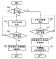
- FIG. 4 is a flowchart showing an example of a parameter changing operation at the special startup time of the hydrogen generator 15 according to the first modification of the first embodiment of the present invention.
- step S117, step S118, and step S119 This flow is obtained by adding step S117, step S118, and step S119 to the flowchart of the first embodiment shown in FIG.
- step S117, step S118, and step S119 This flow is obtained by adding step S117, step S118, and step S119 to the flowchart of the first embodiment shown in FIG.
- the other steps are the same as those of the first embodiment shown in FIG.
- Step S117 When it is determined in step S116 that all parameter changes have not been completed (S116, NO), the controller 6 is supplied with power from the first power supply or is used for independent startup. It is detected whether power is supplied only from the power source 5. When power is supplied from the first power supply (S117, YES), the process proceeds to step S118, and when power is supplied only from the self-sustained startup power supply 5 (S117, NO), the process proceeds to step S112.
- Step S118 When the temperature of the reformer 1 is lower than a predetermined temperature (for example, 250 ° C.) (S118, YES), the process proceeds to Step S119. When this condition is not satisfied (S118, NO), the process proceeds to step S112.
- a predetermined temperature for example, 250 ° C.
- the raw material gas supply amount from the raw material supply device 2 is the second heating amount (for example, 500 W), and the oxygen-containing gas supply amount of the oxygen-containing gas supply device 12 is the eighth flow rate (for example, 0.6 l / min). ).
- the heating amount and the oxygen-containing gas supply amount are returned to the values at the normal startup.
- the hydrogen generator 15 is heated with a high heating amount, so that the reformer 1 existing in the vicinity of the combustor 3 of the hydrogen generator 15 rises at a higher speed than during normal start-up.
- the structure is heated and thermal damage to the structure increases. Therefore, thermal damage to the structure can be reduced by reducing the number of special activations as much as possible.
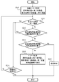
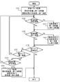
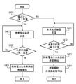
- FIG. 5 is a flowchart showing an example of a parameter changing operation at the normal startup time of the hydrogen generator 15 according to the first modification of the first embodiment of the present invention.
- This flow determines the amount of combustion and the amount of oxygen-containing gas supplied in accordance with the remaining amount of the power source and the power supply for self-sustained startup when the process proceeds to the normal startup operation in step S001 and subsequent steps shown in FIG. It is.
- the raw material gas supply amount from the raw material supplier 2 is the second heating amount (for example, 500 W), and the oxygen-containing gas supply amount of the oxygen-containing gas supplier 12 is the eighth flow rate (for example, 0). .6 l / min).
- Step S011 The controller 6 detects whether power is supplied from the first power supply, or whether power is supplied only from the self-starting power supply 5. When power is supplied from the first power source (S011, YES), the process proceeds to step S015. When power is supplied only from the self-starting power source 5 (S011, NO), the special startup operation is performed. The process proceeds to step S012.
- Step S012 The controller 6 detects the remaining power of the self-starting power source 5.
- the process proceeds to step S015. If this condition is not satisfied (S012, NO), the process proceeds to step S013.
- Step S013 The controller 6 detects the remaining power of the power supply 5 for independent startup.
- the power remaining amount of the self-sustained startup power source 5 is equal to or greater than the amount of power required to complete the special startup (S013, YES)
- the process proceeds to step S014.
- this condition is not satisfied (S013, NO)
- the process proceeds to step S016.
- the raw material gas supply amount from the raw material supply device 2 is the first heating amount (for example, 700 W), and the oxygen-containing gas supply amount of the oxygen-containing gas supply device 12 is the seventh flow rate (for example, 0.7 l / min). ), And shift to the special activation flow.
- Step S015 The controller 6 determines whether the activation of the hydrogen generator 15 is completed. If the activation has been completed (S015, YES), the process proceeds to an end step. If the activation has not been completed (S015, NO), the process proceeds to step S011.
- Step S016 An operation for stopping the hydrogen generator 15 is executed.
- step S015 When the process proceeds from step S015, all the operation parameters of the hydrogen generator 15 are returned to the normal state and controlled according to the command of the hydrogen generation amount. Alternatively, when the process proceeds from step S016, the stop operation is completed. If the process proceeds from step S014, the process proceeds to a special activation flow.
- the hydrogen generator 15 based on the first modification of the first embodiment receives power from the first power source at the time of special startup in which power is supplied only from the self-starting power source 5.
- the temperature of the hydrogen generator 15 can be increased as compared with the normal startup time, and thermal damage to the structure due to an increase in the amount of heating and a decrease in the hydrogen concentration in the hydrogen-containing gas can be suppressed.
- the start-up of the hydrogen generator 15 can be accelerated, and the time for supplying power from the self-starting power supply 5 to the auxiliary machine can be shortened, so that the self-starting power supply 5 can be downsized.
- the hydrogen generator 15 has the same configuration as the hydrogen generator 15 of the first embodiment, and includes a reformer 1, a raw material supplier 2, Combustor 3, combustion air supplier 4, self-starting power source 5, controller 6, water supplier 7, reformer temperature detector 8, CO reducer 9, CO reducer temperature A detector 10, a selective oxidizer 11, an oxygen-containing gas supply device 12, and a selective oxidizer temperature detector 13 are provided.
- a reformer 1 a raw material supplier 2, Combustor 3, combustion air supplier 4, self-starting power source 5, controller 6, water supplier 7, reformer temperature detector 8, CO reducer 9, CO reducer temperature
- a detector 10 a selective oxidizer 11, an oxygen-containing gas supply device 12, and a selective oxidizer temperature detector 13 are provided.
- FIG. 6 is a flowchart showing an example of a second modification of the parameter changing operation at the time of special activation of the hydrogen generator 15 according to the first embodiment of the present invention.
- step S020 and step S021 This flow is obtained by adding step S020 and step S021 to the flowchart of the first modification of the first embodiment shown in FIG. Since other steps are the same as those of the first modification of the first embodiment, detailed description thereof is omitted.
- the raw material gas supply amount from the raw material supply device 2 is the first heating amount (for example, 700 W), and the oxygen-containing gas supply amount of the oxygen-containing gas supply device 12 is the seventh flow rate (for example, 0.7 l / min). ).
- Step S021 The controller 6 determines whether the activation of the hydrogen generator 15 is completed. If the activation has been completed (S021, YES), the process proceeds to an end step. If the activation has not been completed (S021, NO), the process proceeds to step S117.
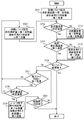
- FIG. 7 is a flowchart showing an example of a second modification of the parameter changing operation at the normal startup time of the hydrogen generator 15 according to the first embodiment of the present invention.
- step S012 in the flowchart of the first modification of the first embodiment shown in FIG. 5 is replaced with step S022, and step S025, step S026, step S027, and step S028 are added. . Since other steps are the same as those of the first modification of the first embodiment, detailed description thereof is omitted.
- Step S022 The controller 6 detects the remaining power of the self-starting power source 5. If the remaining power of the self-sustained startup power supply 5 is equal to or greater than the amount of power required to complete normal startup (S022, YES), the process proceeds to step S028. When this condition is not satisfied (S022, NO), the process proceeds to step S014.
- Step S025 The controller 6 determines whether the activation of the hydrogen generator 15 is completed. If the activation has been completed (S025, YES), the process proceeds to an end step, and if activation has not been completed (S025, NO), the process proceeds to step S026.
- Step S026 The controller 6 detects the remaining power of the power supply 5 for independent startup. If the remaining power of the self-sustained startup power supply 5 is equal to or greater than the amount of power required to complete the special startup (S026, YES), the process proceeds to step S027. When this condition is not satisfied (S026, NO), the process proceeds to step S016.
- Step S027 It is determined whether the temperature of the reformer 1 is lower than a predetermined temperature (for example, 250 ° C.). When the temperature of the reformer 1 is lower than the predetermined temperature (S027, YES), the process proceeds to step S011. When this condition is not satisfied (S027, NO), the process proceeds to step S025.
- a predetermined temperature for example, 250 ° C.
- the raw material gas supply amount from the raw material supply device 2 is the second heating amount (for example, 500 W), and the oxygen-containing gas supply amount of the oxygen-containing gas supply device 12 is the eighth flow rate (for example, 0.6 l / min). ).
- the hydrogen generation device 15 based on the second modification of the first embodiment is powered from the normal startup operation in which the power from the first power supply is supplied and the power supply 5 for the independent startup only.
- the power supply source is continuously monitored, and when the power supply source changes, the normal activation or the special activation can be performed.
- the hydrogen generator is used when special start-up is required while minimizing the number of special start-ups. 15 can be started quickly, and the time for supplying power from the self-starting power supply 5 to the auxiliary machine can be shortened, so that the self-starting power supply 5 can be downsized.
- a hydrogen generator 15 according to a third modification of the first embodiment is the same as the hydrogen generator 15 of the first embodiment, and includes a reformer 1, a raw material supplier 2, and a combustor. 3, combustion air supply device 4, power supply 5 for self-sustained startup, controller 6, water supply device 7, reformer temperature detector 8, CO reducer 9, and CO reducer temperature detector 10, a selective oxidizer 11, an oxygen-containing gas supply device 12, and a selective oxidizer temperature detector 13.
- control is performed according to the time from the start of combustion regardless of the temperatures of the reformer 1 and the selective oxidizer 11.
- FIG. 8 is a flowchart showing an example of a third modification of the parameter changing operation at the time of special activation of the hydrogen generator 15 according to the first embodiment of the present invention.
- step S112 is replaced with step S122 and step S114 with step S124 in the flowchart of the first embodiment shown in FIG. Since other steps are the same as those in the first embodiment, detailed description thereof is omitted.
- Step S122 When a predetermined time (for example, 30 minutes) or more has elapsed from the start of combustion in the combustor 3 (S122, NO), the process proceeds to Step S113. When this condition is not satisfied (S122, YES), the process proceeds to step S124.
- a predetermined time for example, 30 minutes
- Step S124 When the fifth time (for example, 35 minutes) or more has elapsed from the start of combustion in the combustor 3 (S124, NO), the process proceeds to Step S115. When this condition is not satisfied (S124, YES), the process proceeds to step S116.
- the temperature of the hydrogen generator 15 can be increased, and the self-starting operation can be performed. Since the time for supplying power from the power source 5 to the auxiliary machine can be shortened, the self-starting power source 5 can be reduced in size.
- the hydrogen generator 15 according to the fourth modification of the first embodiment is the same as that of the hydrogen generator 15 of the first embodiment, and is the reformer 1, the raw material supplier 2, and the combustor. 3, combustion air supply device 4, power supply 5 for self-sustained startup, controller 6, water supply device 7, reformer temperature detector 8, CO reducer 9, and CO reducer temperature detector 10, a selective oxidizer 11, an oxygen-containing gas supply device 12, and a selective oxidizer temperature detector 13. Then, in the parameter changing operation at the time of the special start-up, the control is performed according to the time from the start of combustion regardless of the temperature of the reformer 1 and the selective oxidizer 11, and further, the power supply from the first power source is performed It is to shift to normal startup.
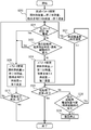
- FIG. 9 is a flowchart showing an example of a fourth modification of the parameter changing operation in the special activation of the hydrogen generator 15 according to the first embodiment of the present invention.
- Step S117, Step S119, and Step S128 are the same as those of the first modification of the first embodiment, and other steps are the same as those of the third modification of the first embodiment. Omitted.
- Step S128 If the elapsed time from the start of combustion in the combustor 3 is less than a predetermined time (for example, 30 minutes) (S128, YES), the process proceeds to Step S119. When this condition is not satisfied (S128, NO), the process proceeds to step S122.
- a predetermined time for example, 30 minutes
- the reformer temperature detector 8 does not function due to a failure or the like, as in the first modification of the first embodiment, when power is supplied from the first power source, Therefore, it is possible to shift to normal activation, and to suppress thermal damage to the structure and the catalyst.
- the self-starting power supply 5 can be reduced in size.
- a hydrogen generator 15 according to the second embodiment of the present invention has the same configuration as the hydrogen generator 15 of the first embodiment shown in FIG. 1, and includes a reformer 1 and a raw material supplier 2. , A combustor 3, a combustion air supply 4, a self-starting power supply 5, a controller 6, a water supply 7, a reformer temperature detector 8, a CO reducer 9, and a CO reduction A temperature detector 10, a selective oxidizer 11, an oxygen-containing gas supply device 12, and a selective oxidizer temperature detector 13 are provided.
- FIG. 10 is a flowchart showing an example of the operation of the hydrogen generator 15 according to the second embodiment of the present invention.
- steps S101, S102, and S103 in the flowchart of the first embodiment shown in FIG. 2 are replaced with steps S201, S202, and S203, respectively.
- the other steps are the same as those of the first embodiment shown in FIG.
- Step S201 In response to a command from the controller 6 that has detected that power is supplied from the self-sustained startup power supply 5, power is supplied from the self-sustained startup power supply 5 to the raw material supplier 2 and the combustion air supplier 4.
- the First after an amount of combustion air corresponding to the amount of source gas is supplied to the combustor 3, the source gas is supplied at a second heating amount (for example, 500 W).
- Step S202 In the combustor 3, the raw material gas ignited by the ignition device is combusted together with the combustion air. Heat generated by combustion in the combustor 3 is supplied to the reformer 1, the CO reducer 9, and the selective oxidizer 11 to raise the temperature of the reformer 1, the CO reducer 9, and the selective oxidizer 11. At the same time, heating with a heater may be used in combination.
- Step S203 When the reformer temperature detector 8 detects that the reformer 1 is at a first temperature (eg, 180 ° C.) lower than the second temperature (eg, 200 ° C.), Alternatively, when a first time (for example, 10 minutes) shorter than a second time (for example, 15 minutes) has elapsed from the start of combustion in the combustor 3, water is supplied from the water supply device 7 to a second flow rate (for example, The first flow rate (for example, 3 cc / min) is less than 5 cc / min.
- a first time for example, 10 minutes
- a second time for example, 15 minutes
- the CO reducer temperature detector 10 and the selective oxidizer temperature detector 13 depends on either the CO reducer temperature detector 10 or the selective oxidizer temperature detector 13.
- a threshold value may be set in advance for the measured temperature, and water supply may be started. In this case, for example, the threshold value can be 120 ° C. in the CO reducer temperature detector 10 and 110 ° C. in the selective oxidizer temperature detector 13.
- step S003 water supply can be started earlier than in step S003.
- the supplied water and the raw material gas undergo a steam reforming reaction in the reformer 1, and the raw material gas becomes a reformed gas to increase its volume, and the CO reducer 9 and the selective oxidizer 11 on the downstream side. Circulate.
- step S003 by reducing the flow rate of water as compared with step S003, the amount of water vapor contained in the reformed gas by the steam reforming reaction is reduced, and the dew point of the reformed gas is lowered. Thereby, the dew condensation to the catalyst in the downstream CO reduction device 9 and the selective oxidizer 11 can be suppressed, and the durability reduction of the catalyst can be suppressed.
- this step includes steps S101 and S101.
- a higher effect can be obtained by combining with an increase in the amount of heating to the hydrogen generator in the combustor 3 shown in S102.
- the temperature of the hydrogen generator 15 can be increased at the time of special startup in which power is supplied only from the self-starting power supply 5 as compared to the normal startup in which power is supplied from the first power supply.
- the start-up of the hydrogen generator 15 can be accelerated, and the time for supplying power from the self-sustained startup power supply 5 to the auxiliary machine can be shortened, so that the self-sustained startup power supply 5 can be downsized.
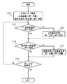
- FIG. 11 is a flowchart showing an example of a parameter changing operation at the time of special activation of the hydrogen generator 15 according to the second embodiment of the present invention.
- This flow is for determining the amount of water and the supply amount of the oxygen-containing gas in accordance with the temperatures of the CO reducer 9 and the selective oxidizer 11 in the case of shifting to the special activation after step S201 in FIG. is there.
- step S111 in the flowchart of the first embodiment shown in FIG. 3 with step S211, step S112 with step S212, and step S113 with step S213. Since other steps are the same as those in the first embodiment, detailed description thereof is omitted.
- the amount of water supplied from the water supply device 7 is the first flow rate (for example, 3 cc / min), and the amount of oxygen-containing gas supply of the oxygen-containing gas supply device 12 is the seventh flow rate (for example, 0 .7 l / min).
- Step S212 When the temperature of the CO reducer 9 is equal to or higher than the third temperature (for example, 100 ° C.) (S212, NO), the process proceeds to Step S213. When this condition is not satisfied (S212, YES), the process proceeds to step S114.
- the third temperature is a temperature at which the CO reducer 9 and the downstream catalyst are not wetted by the supplied steam, and is determined by the amount of water supplied to the reformer 1. Preferably it is 100 degreeC or more.
- Step S213 The controller 6 controls the amount of water supplied from the water supply device 7 to a third flow rate (for example, 7 cc / min) higher than the first flow rate (for example, 3 cc / min).
- the third flow rate may be the same as the second flow rate (for example, 5 cc / min).
- the hydrogen generator 15 according to the second embodiment can perform normal startup in which power is supplied from the first power supply during special startup in which power is supplied only from the self-starting power supply 5. Compared to time, the temperature of the hydrogen generator 15 can be increased, and the deterioration of the catalyst due to carbon deposition and the decrease in the amount of hydrogen in the hydrogen-containing gas can be suppressed.
- the hydrogen generator 15 can be started up quickly, and the time for supplying power from the self-starting power source 5 to the auxiliary machine can be shortened, so that the self-starting power source 5 can be reduced in size.
- a hydrogen generator 15 according to a first modification of the second embodiment of the present invention is the same as the hydrogen generator 15 of the first embodiment, and includes a reformer 1, a raw material supplier 2, and the like. , Combustor 3, combustion air supplier 4, self-starting power source 5, controller 6, water supplier 7, reformer temperature detector 8, CO reducer 9, CO reducer A temperature detector 10, a selective oxidizer 11, an oxygen-containing gas supply device 12, and a selective oxidizer temperature detector 13 are provided. In the parameter changing operation, control is performed according to the time from the start of combustion regardless of the temperatures of the reformer 1 and the selective oxidizer 11.
- FIG. 12 is a flowchart showing an example of a first modification of the parameter changing operation at the time of special activation of the hydrogen generator 15 according to the second embodiment of the present invention.
- step S212 of the second embodiment shown in FIG. 11 This flow is obtained by replacing step S212 of the second embodiment shown in FIG. 11 with step S222 and replacing step S114 with step S124.
- Other steps are the same as those in the second embodiment, and thus detailed description thereof is omitted.
- Step S222 When a predetermined time (for example, 30 minutes) or more has elapsed from the start of combustion in the combustor 3 (S222, NO), the process proceeds to Step S213. When this condition is not satisfied (S222, YES), the process proceeds to step S124.
- a predetermined time for example, 30 minutes
- Step S124 When the fifth time (for example, 35 minutes) or more has elapsed from the start of combustion in the combustor 3 (S224, NO), the process proceeds to Step S115. When this condition is not satisfied (S224, YES), the process proceeds to step S116.
- the temperature of the hydrogen generator 15 can be increased, and the self-starting power supply Since the time for supplying power to the auxiliary machine from 5 can be shortened, the self-starting power source 5 can be reduced in size.
- the hydrogen generator 15 according to the third embodiment of the present invention is the same as the hydrogen generator 15 of the first embodiment shown in FIG. 1, and includes the reformer 1, the raw material supplier 2, and the like. , Combustor 3, combustion air supplier 4, self-starting power source 5, controller 6, water supplier 7, reformer temperature detector 8, CO reducer 9, CO reducer A temperature detector 10, a selective oxidizer 11, an oxygen-containing gas supply device 12, and a selective oxidizer temperature detector 13 are provided.
- FIG. 13 is a flowchart showing an example of the operation of the hydrogen generator 15 according to the third embodiment of the present invention.
- step S203 is replaced with step S303 in the flowchart of the second embodiment shown in FIG.
- Other steps are the same as those in the second embodiment, and thus detailed description thereof is omitted.
- Step S303 At the time of special startup in which power is supplied only from the power supply 5 for independent startup, water is supplied at a fourth flow rate (for example, 8 cc / min) higher than the second flow rate (for example, 5 cc / min). The reforming reaction proceeds.
- a fourth flow rate for example, 8 cc / min
- the second flow rate for example, 5 cc / min
- step S003 This increases the amount of water supply compared to step S003, which is normally started.
- the supplied water and the raw material gas cause a steam reforming reaction in the reformer 1, the raw material gas becomes the reformed gas, and its volume is increased.
- the CO reducer 9 and the selective oxidizer 11 on the downstream side are increased. Circulate.
- the steam reforming reaction in the reformer 1 has a higher temperature than the reaction in the CO reducer 9 and the selective oxidizer 11, heat transfer occurs from the reformed gas to the CO reducer 9 and the selective oxidizer 11.
- the flow rate increases as the amount of gas flowing increases, and heat transfer is promoted.
- the amount of water is large, the steam reforming reaction is promoted, the amount of reformed gas is increased, the flow rate is increased, and heat transfer is promoted.
- step S303 which is a special start-up, heat transfer from the reformer 1 to the CO reducer 9 and the selective oxidizer 11 existing downstream of the reformer 1 is promoted compared to step S003. Therefore, these temperature increases can be accelerated.
- this step is performed in the first implementation.
- a suitable temperature 250 ° C. or higher, preferably 350 ° C. or higher
- the amount of water may be controlled as in step S203 of the second embodiment.
- the temperature of the reformer 1 is low, water is not sufficiently consumed by the steam reforming reaction, so that the dew point of the reformed gas becomes high.
- step S203 by limiting the amount of water as in step S203, the amount of water vapor contained in the reformed gas by the steam reforming reaction is reduced and the dew point of the reformed gas is lowered. 9 and the selective oxidizer 11 can suppress condensation even at a low temperature, so that a more preferable effect can be obtained.
- the temperature of the hydrogen generator 15 can be increased at the time of special startup in which power is supplied only from the self-starting power supply 5 as compared to the normal startup in which power is supplied from the first power supply.
- the start-up of the hydrogen generator 15 can be accelerated, and the time for supplying power from the self-sustained startup power supply 5 to the auxiliary machine can be shortened, so that the self-sustained startup power supply 5 can be downsized.
- FIG. 14 is a flowchart showing an example of a parameter changing operation at the time of special activation of the hydrogen generator 15 according to the third embodiment of the present invention.
- This flow determines the amount of water and the supply amount of the oxygen-containing gas in accordance with the temperatures of the CO reducer 9 and the selective oxidizer 11 when the process proceeds to the special activation after step S201 in FIG.
- step S211 is replaced with step S311, step S212 with step S312 and step S213 with step S313 in the flowchart of the second embodiment shown in FIG.
- Other steps are the same as those in the second embodiment, and thus detailed description thereof is omitted.
- Step S311 As initial values, the amount of water supplied from the water supply device 7 is the fourth flow rate (for example, 8 cc / min), and the amount of oxygen-containing gas supply of the oxygen-containing gas supply device 12 is the seventh flow rate (for example, 0 .7 l / min).
- Step S312 When the temperature of the CO reducer 9 is equal to or higher than the fourth temperature (for example, 130 ° C.) (S312, NO), the process proceeds to Step S313. When this condition is not satisfied (S312, YES), the process proceeds to step S114.
- the fourth temperature for example, 130 ° C.
- Step S313 The controller 6 controls the amount of water supplied from the water supplier 7 to a sixth flow rate (for example, 6 cc / min) that is smaller than the fourth flow rate (for example, 8 cc / min).
- a sixth flow rate for example, 6 cc / min
- the fourth flow rate for example, 8 cc / min
- the sixth flow rate may be the same as the second flow rate (for example, 5 cc / min).
- the hydrogen generator 15 based on the third embodiment is specially supplied with power only from the self-starting power source 5.
- the temperature of the hydrogen generator 15 can be increased more quickly than in the case of the normal start-up in which power is supplied from the first power supply, and a decrease in thermal efficiency can be suppressed.
- the hydrogen generator 15 according to the first modification of the third embodiment is the same as the hydrogen generator 15 of the first embodiment, and includes the reformer 1, the raw material supplier 2, and the combustor 3.
- a combustion air supply device 4 a self-starting power source 5, a controller 6, a water supply device 7, a reformer temperature detector 8, a CO reducer 9, and a CO reducer temperature detector 10.
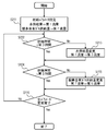
- FIG. 15 is a flowchart showing an example of a first modification of the parameter changing operation in the special activation of the hydrogen generator 15 according to the third embodiment of the present invention.
- Step S117 is the same as that of the first modification example of the first embodiment, and the other steps are the same as those of the third embodiment, and thus description thereof is omitted.
- Step S318 When the temperature of the CO reducer 9 is lower than the fourth temperature (for example, 130 ° C.) (S318, YES), the process proceeds to Step S319. When this condition is not satisfied (S318, NO), the process proceeds to step S312.
- the water supply amount from the water supply unit 7 is the fifth flow rate (for example, 5 cc / min), and the oxygen-containing gas supply amount of the oxygen-containing gas supply unit 12 is the eighth flow rate (for example, 0.6 l / min). ).
- a hydrogen generator 15 according to a second modification of the third embodiment of the present invention is the same as the hydrogen generator 15 of the first embodiment, and includes a reformer 1, a raw material supplier 2, and the like. , Combustor 3, combustion air supplier 4, self-starting power source 5, controller 6, water supplier 7, reformer temperature detector 8, CO reducer 9, CO reducer A temperature detector 10, a selective oxidizer 11, an oxygen-containing gas supply device 12, and a selective oxidizer temperature detector 13 are provided. In the parameter changing operation, control is performed according to the time from the start of combustion regardless of the temperature of the reformer 1 and the selective oxidizer 11.
- FIG. 16 is a flowchart showing an example of a second modification of the parameter changing operation at the time of special activation of the hydrogen generator 15 according to the third embodiment of the present invention.
- step S312 This flow is obtained by replacing step S312 with step S322 and step S114 with step S324 in the flowchart of the third embodiment shown in FIG.
- the other steps are the same as in the third embodiment, and thus detailed description thereof is omitted.
- Step S322 When a fourth time (for example, 30 minutes) or more has elapsed from the start of combustion in the combustor 3 (S322, NO), the process proceeds to Step S313. When this condition is not satisfied (S322, YES), the process proceeds to step S324.
- Step S324 When the fifth time (for example, 35 minutes) or more has elapsed from the start of combustion in the combustor 3 (S324, NO), the process proceeds to Step S115. When this condition is not satisfied (S324, YES), the process proceeds to step S116.
- the temperature of the hydrogen generator 15 can be increased, and the self-starting operation can be performed. Since the time for supplying power from the power source 5 to the auxiliary machine can be shortened, the self-starting power source 5 can be reduced in size.
- a hydrogen generator 15 according to a third modification of the third embodiment is the same as the hydrogen generator 15 of the first embodiment, and includes a reformer 1, a raw material supplier 2, and a combustor. 3, combustion air supply device 4, power supply 5 for self-sustained startup, controller 6, water supply device 7, reformer temperature detector 8, CO reducer 9, and CO reducer temperature detector 10, a selective oxidizer 11, an oxygen-containing gas supply device 12, and a selective oxidizer temperature detector 13. Then, in the parameter changing operation at the time of the special start-up, the control is performed according to the time from the start of combustion regardless of the temperature of the reformer 1 and the selective oxidizer 11, and further, the power supply from the first power source is performed Is to shift to normal startup.
- FIG. 17 is a flowchart showing an example of a third modification of the parameter changing operation at the time of special activation of the hydrogen generator 15 according to the third embodiment of the present invention.
- Step S117 is the same as the first modification of the first embodiment
- step S319 is the same as the first modification of the third embodiment
- other steps are the same as those of the third embodiment. Since it is the same as that of the form, detailed description thereof is omitted.
- Step S328 If the elapsed time from the start of combustion of the combustor 3 is less than the fourth time (for example, 30 minutes) (S328, YES), the process proceeds to Step S319. When this condition is not satisfied (S328, NO), the process proceeds to step S322.
- the temperature of the hydrogen generator 15 can be increased, and the self-starting operation can be performed. Since the time for supplying power from the power source 5 to the auxiliary machine can be shortened, the self-starting power source 5 can be reduced in size.
- the water supply amount is reduced earlier than at the time of the special start-up, so that the thermal efficiency of the hydrogen generator 15 is improved earlier than when the special start-up is continued. The risk of wetness of the catalyst due to an increase in the amount of water supply can be reduced.
- the fuel cell system according to the fourth embodiment of the present invention includes, in addition to any one of the hydrogen generators 15 of the first embodiment, the second embodiment, and the third embodiment. Further, a fuel cell 16 is provided.
- FIG. 18 is a block diagram showing an example of a schematic configuration of the fuel cell system 100 according to the fourth embodiment of the present invention.
- the fuel cell 16 generates power using the hydrogen-containing gas supplied from the hydrogen generator 15.
- the fuel cell 16 may be any type of fuel cell.
- a polymer electrolyte fuel cell (PEFC), a solid oxide fuel cell, or a phosphoric acid fuel cell can be used.
- any one of the hydrogen generator 15 of the first embodiment, the second embodiment, and the third embodiment may be used. Is the same as described above, and a detailed description thereof is omitted.
- FIG. 19 is a flowchart showing an example of the operation of the fuel cell system 100 according to the fourth embodiment of the present invention.
- Step S400 The controller 6 that has received the start command detects whether power is supplied from the first power source or power is supplied from the self-starting power source 5.
- the routine proceeds to step S401 of the normal startup operation, and when power is supplied from the self-sustained startup power source 5 (S400, NO), special processing is performed.
- the process proceeds to step S411 of the starting operation.
- Step S401 The hydrogen generator 15 is started normally and the temperature is raised.
- Step S402 It is determined whether the temperature of the reformer 1 of the hydrogen generator 15 is equal to or higher than a sixth temperature (for example, 550 ° C.). If the temperature of the reformer 1 is equal to or higher than the sixth temperature (eg, 550 ° C.) (S402, YES), the process proceeds to step S403, and if the temperature of the reformer 1 is lower than the sixth temperature (eg, 550 ° C.) ( (S402, NO) The process proceeds to step S401.
- a sixth temperature for example, 550 ° C.
- Step S403 Hydrogen is supplied to the fuel cell 16 to start power generation.
- Step S411 A special start-up operation of the hydrogen generator 15 is started and the temperature is raised.
- Step S412 It is determined whether the temperature of the reformer 1 is equal to or higher than a seventh temperature (for example, 500 ° C.) lower than the sixth temperature (for example, 550 ° C.). If the temperature of the reformer 1 is equal to or higher than the seventh temperature (eg, 500 ° C.) (S412, YES), the process proceeds to step S413, and the temperature of the reformer 1 is lower than the seventh temperature (eg, 500 ° C.). If (S412, NO), the process proceeds to step S411.
- a seventh temperature for example, 500 ° C.
- the sixth temperature for example, 550 ° C.
- Step S413 Hydrogen is supplied to the fuel cell 16 to start power generation.
- Step S414 The auxiliary machine is driven by the generated power, and the temperature of the hydrogen generator 15 is continuously increased so that more hydrogen can be supplied than the preset minimum power generation amount, thereby increasing the hydrogen generation amount. Increase power generation.
- step S401 and step S402. it is possible to shift to power generation at an early stage as compared with the normal startup shown in step S401 and step S402. For this reason, the time for supplying electric power to drive the catcher from the self-starting power supply 5 is shortened, and the power supply amount from the self-starting power supply 5 can be reduced. Therefore, the self-starting power supply 5 can be reduced in size.
- a fuel cell system 100 according to a first modification of the fourth embodiment of the present invention has the same configuration as that of the fourth embodiment, and includes a hydrogen generator 15 and a fuel cell 16. Since the above configuration is the same as that of the fourth embodiment, detailed description thereof is omitted.
- FIG. 20 is a flowchart showing an example of a first modification of the operation of the fuel cell system according to the fourth embodiment of the present invention.
- step S402 This flow is obtained by replacing step S402 with step S422 and step S412 with step S432 in the flowchart of the fourth embodiment shown in FIG.
- the other steps are the same as those in the fourth embodiment, and a description thereof will be omitted.
- Step S422 It is determined whether the hydrogen-containing gas supply amount from the hydrogen generator 15 is equal to or greater than the first supply amount (for example, 5 l / min). If a hydrogen-containing gas of a first supply amount (for example, 5 l / min) or more is supplied (S422, YES), the process proceeds to step S403, and a hydrogen-containing gas of a first supply amount (for example, 5 l / min) or more. Is not supplied (S422, NO), the process proceeds to step S401.
- the first supply amount for example, 5 l / min
- Step S403 Hydrogen is supplied to the fuel cell 16 to start power generation.
- Step S411 A special start-up operation of the hydrogen generator 15 is started, and the temperature is raised.
- Step S432 The controller 6 determines whether the hydrogen-containing gas supply amount from the hydrogen generator 15 is equal to or greater than a second supply amount (eg, 4 l / min) that is less than the first supply amount (eg, 5 l / min). It is determined by. If the hydrogen-containing gas of the second supply amount (for example, 4 l / min) or more is supplied (S432, YES), the process proceeds to step S413, and the hydrogen-containing gas of the second supply amount (for example, 4 l / min) or more. Is not supplied (S432, NO), the process proceeds to step S411.
- a second supply amount eg, 4 l / min
- Step S413 Hydrogen is supplied to the fuel cell 16 to start power generation.
- Step S414 The controller 6 continues to raise the temperature of the hydrogen generator 15 so that the auxiliary machine is driven by the generated power and hydrogen can be supplied in excess of the preset minimum power generation amount. Increase hydrogen production and power generation.
- step S422. it is possible to shift to power generation earlier than in the normal startup shown in step S422. For this reason, the time for supplying electric power to drive the catcher from the self-starting power supply 5 is shortened, and the power supply amount from the self-starting power supply 5 can be reduced. Therefore, the self-starting power supply 5 can be reduced in size.
- the hydrogen generator 15 includes the reformer 1 that reforms a raw material containing hydrocarbons to generate a hydrogen-containing gas, and the raw material supplier that supplies the raw material to the reformer 1. 2, a combustor 3 that burns at least one of a raw material and a hydrogen-containing gas to heat the reformer 1, and a combustion air supply device 4 that supplies combustion air to the combustor 3.
- a self-starting power source 5 that supplies power to at least the raw material supplier 2 and the combustion air supplier 4 and a controller 6 are provided.
- the controller 6 starts by supplying power from at least a first power source other than the self-starting power source 5 to the auxiliary equipment including the raw material supplier 2 and the combustion air supplier 4, and power from the first power source
- the controller 6 is configured to control so that the first heating amount combusted in the combustor 3 is larger than the second heating amount combusted in the combustor 3 during normal startup at the time of special startup. ing.
- the amount of heat input to the hydrogen generator 15 increases during a special start-up, so that the rate of temperature rise to the appropriate temperature of the catalyst is increased, and the power supply time from the self-starting power supply 5 to the auxiliary machine is shortened.
- the amount of power supply can be reduced, and the self-starting power source 5 can be reduced in size.
- the controller 6 when the controller 6 is at a special start-up, when the temperature of the reformer 1 becomes equal to or higher than a preset temperature, or when a predetermined time has elapsed from the start of combustion of the combustor 3, the combustor 3. It may be configured to control so that the amount of heat burned at the third heating amount is lower than the first heating amount.
- the hydrogen generator 15 also reforms a raw material containing hydrocarbons to generate a hydrogen-containing gas, a raw material supplier 2 that supplies the raw material to the reformer, and a raw material and a hydrogen-containing gas.
- a combustor 3 that burns at least one to heat the reformer, and a water supplier 7 that supplies water to the reformer 1 are provided.
- a self-starting power source 5 that supplies power to at least the raw material supplier 2 and the water supplier 7 and a controller 6 are provided.
- the controller 6 is started by supplying power from at least a first power source other than the self-starting power source 5 to the auxiliary machine including the raw material supplier 2 and the water supplier 7, and from the first power source
- it may be configured to perform control to start by supplying power to the auxiliary machine only from the self-starting power supply 5.
- the first time from the start of heating of the reformer 1 to the start of water supply from the water supplier 7 to the reformer 1 at the special start-up is the start of heating of the reformer 1 at the normal start-up. Therefore, it may be configured to perform control so as to be shorter than the second time until water supply from the water supply device 7 to the reformer 1 is started.
- the steam reforming of the hydrocarbon is started earlier than the normal start-up or from the stage where the temperature of the reformer 1 is low. Since the gas volume is increased by the steam reforming, the heat transfer to the catalyst on the downstream side of the reformer 1 is started early, and the temperature rise of the catalyst can be accelerated.
- the downstream catalyst include a shift catalyst, a methanation catalyst, and a selective oxidation catalyst.
- the hydrogen generator 15 also reforms a raw material containing hydrocarbons to generate a hydrogen-containing gas, a raw material supplier 2 that supplies the raw material to the reformer 1, and the raw material and hydrogen-containing gas.
- a raw material supplier 2 that supplies the raw material to the reformer 1
- the raw material and hydrogen-containing gas are provided with a combustor 3 that burns at least one of them to heat the reformer 1, and a water supply device 7 that supplies water to the reformer 1.
- a reformer temperature detector 8 that detects the temperature of the reformer 1, a self-starting power source 5 that supplies power to at least the raw material supplier 2 and the water supplier 7, and a controller 6 are provided. .
- the controller 6 is activated by supplying power from at least a first power supply other than the self-starting power supply 5 to an auxiliary machine including the raw material supply device 2 and the water supply device 7 at the time of normal activation. It may be configured to start by supplying power to the auxiliary machine only from the self-starting power supply 5 at the time of special starting where supply cannot be obtained. Then, when the temperature of the reformer 1 reaches the first temperature at the special start-up, water supply to the reformer 1 is started, and at the normal start-up, the temperature of the reformer 1 becomes a second temperature higher than the first temperature. If it becomes, it may be comprised so that it may control so that the water supply to the reformer 1 may be started.
- the steam reforming of the hydrocarbon is started earlier than the normal start-up or at a stage where the temperature of the reformer 1 is low. Since the gas volume is increased by steam reforming, heat transfer to the catalyst on the downstream side of the reforming site is started early, and the temperature rise of the catalyst can be accelerated. In addition, by controlling the temperature of the reformer 1 regardless of the time from the start of heating, at least one of the heat amount of the raw material gas, the change in the outside air temperature, and the difference in the temperature rise time due to the time since the previous activation. It is possible to correct the above, and it is possible to start the heat transfer between the catalysts earlier.
- controller 6 controls to supply water to the reformer 1 at a first flow rate at the time of special activation, and to supply water to the reformer 1 at a second flow rate higher than the first flow rate at the time of normal activation. It may be configured as follows.
- a CO reducer 9 that reduces carbon monoxide in the hydrogen-containing gas supplied from the reformer 1 and a CO reducer temperature detector 10 that detects the temperature of the CO reducer may be further provided.
- the controller 6 exceeds the first flow rate. You may be comprised so that water may be supplied to the reformer 1 with many 3rd flow rates.
- the third flow rate may be the same flow rate as the second flow rate.
- the hydrogen generator 15 also reforms a raw material containing hydrocarbons to generate a hydrogen-containing gas, a raw material supplier 2 that supplies the raw material to the reformer 1, and the raw material and hydrogen-containing gas.
- a combustor 3 that burns at least one of them to heat the reformer 1, a water supply device 7 that supplies water to the reformer 1, and a reformer temperature detector 8 that detects the temperature of the reformer 1. And may be provided. And you may provide the power supply 5 for the independent starting which supplies electric power to the raw material supply device 2 and the water supply device 7, and the controller 6 at least.
- the controller 6 is activated by supplying power from at least a first power supply other than the self-starting power supply 5 to an auxiliary machine including the raw material supply device 2 and the water supply device 7 at the time of normal activation.
- power is supplied to the auxiliary machine only from the power supply 5 for independent startup, and the controller 6 supplies water to the reformer 1 at the fourth flow rate at the time of special startup. It may be configured to control to supply water to the reformer 1 at a fifth flow rate smaller than the fourth flow rate at startup.
- the steam reforming reaction in the reformer 1 is promoted more than at the normal startup, and the gas volume becomes larger than at the normal startup. Therefore, heat transfer to the CO reducer 9 or the selective oxidizer 11 that is operated at a relatively lower temperature than the reformer 1 is promoted, and the temperature rise of the catalyst on the downstream side of the reformer 1 can be accelerated. it can.
- a CO reducer 9 that reduces carbon monoxide in the hydrogen-containing gas supplied from the reformer 1 and a CO reducer temperature detector 10 that detects the temperature of the CO reducer 9 are further provided. Also good. Then, when the temperature of the CO reducer 9 becomes equal to or higher than the fourth temperature or when the fourth time has elapsed from the start of combustion of the combustor 3, the controller 6 exceeds the fourth flow rate. It may be configured to control to supply water to the reformer 1 with a small sixth flow rate.
- the sixth flow rate may be the same as at least one of the second flow rate and the fifth flow rate.
- a selective oxidizer 11 that reduces carbon monoxide in the hydrogen-containing gas supplied from the reformer 1 by an oxidation reaction, and an oxygen-containing gas supply device 12 that supplies the oxygen-containing gas to the selective oxidizer 11 are provided. It may be. Then, the controller 6 supplies the oxygen-containing gas to the selective oxidizer 11 at the seventh flow rate during the special activation, and supplies the oxygen-containing gas to the selective oxidizer 11 at the eighth flow rate that is smaller than the seventh flow rate during the normal activation. You may be comprised so that it may control.
- the selective oxidizer 11 since the selective oxidizer 11 generates heat due to the oxidation reaction of the hydrogen-containing gas or the fuel gas in the CO reducer 9, it is possible to raise the temperature of the selective oxidizer 11 earlier than during normal operation.
- a selective oxidizer temperature detector 13 for detecting the temperature of the selective oxidizer 11 is further provided, and the controller 6 performs combustion when the temperature of the selective oxidizer 11 becomes equal to or higher than the fifth temperature at the special start-up.
- the oxygen-containing gas may be controlled to be supplied to the selective oxidizer 11 at a ninth flow rate smaller than the seventh flow rate.
- the ninth flow rate may be the same as the eighth flow rate.
- controller 6 may be configured to control to shift to normal startup when power is supplied from a first power source other than the independent startup power source 5 during special startup.
- the normal activation when power is supplied from the first power source during the special activation, the normal activation is started, so that the number of special activations can be reduced.
- special start-up it is heated at a higher heating amount than normal start-up, or water is supplied from an earlier timing, that is, when the catalyst is at a lower temperature than normal start-up. The possibility of increases. However, these influences can be suppressed by reducing the number of special activations.
- the controller normally supplies power from the first power supply other than the self-starting power supply 5 during the special start-up, and when the elapsed time from the start of combustion of the combustor 3 is less than a predetermined time. You may be comprised so that it may control to transfer to starting.
- the hydrogen generator 15 is heated with a higher combustion amount than during the normal start-up.
- the reformer 1 existing in the vicinity of the combustor 3 of the hydrogen generator 15 is heated at a higher speed than during normal startup. Therefore, the thermal damage to the structure is increased as compared with the normal startup.
- water is supplied to the reformer 1 with a larger amount of water supply than at the time of normal start-up. For this reason, when the temperature of a part of catalyst is lower than expected, the risk of wetness of the catalyst increases.
- the combustion amount and the water supply amount are reduced from the initial values at the time of special activation. For this reason, the effect is small even if it shifts to normal activation at this stage.
- at least one of the heating amount and the water supply amount is increased from the normal startup, when power is supplied from the first power supply, at least one of the heating amount and the water supply amount Is changed to the value at the time of normal startup, so that it is possible to effectively reduce the thermal influence on the structure and the risk of wetness of the catalyst.
- the controller 6 shifts to normal startup when power is supplied from the first power source other than the self-starting power source during the special startup and the temperature of the reformer 1 is lower than the predetermined temperature. You may be comprised so that it may control.
- controller 6 supplies power from the first power source other than the self-starting power source 5 during the special starting and the temperature of the CO reducer 9 is lower than the fourth temperature, or the combustor
- control may be performed so as to shift to normal activation.
- controller 6 may be configured to control to shift to the special activation when the power supply from the first power source other than the self-sustained activation power source 5 is interrupted during the normal activation.
- the power supply amount from the self-starting power supply 5 is extended and the power supply amount is increased when starting with normal startup as compared with special startup. For this reason, in order to be able to start even in such a case, it is necessary to increase the power supply 5 for independent startup.
- the power supply amount from the self-start start-up power supply 5 to the auxiliary machine can be reduced by shortening the start-up time. As a result, the self-starting power source 5 can be reduced in size.
- the controller 6 continues to monitor the remaining amount of power of the self-starting power supply 5 after the power supply from the first power supply other than the self-starting power supply 5 is interrupted during normal start-up, and the self-starting power supply When the remaining power of 5 falls below the amount of power required to continue the activation by the normal activation, the control may be configured to shift to the special activation.
- the power capacity of the self-starting power supply 5 has a margin for the amount of power required to complete startup by normal startup, startup is continued by normal startup. Therefore, the number of special activations can be minimized, and the influence on the structure and the catalyst due to the special activation can be suppressed.
- the controller 6 detects the remaining power of the self-starting power supply 5 and detects the detected self-starting power supply.
- the configuration may be such that when the remaining amount of power of the power source 5 is lower than the amount of power necessary for continuing the activation by the special activation, the activation operation is stopped.
- controller 6 continues to monitor the remaining amount of power of the self-starting power supply 5 after the power supply from the first power supply other than the self-starting power supply 5 is interrupted during normal start-up, and the self-starting power supply
- the configuration may be such that the activation operation is stopped when the remaining power of 5 falls below the amount of power necessary to continue the activation by the special activation.
- the remaining power amount estimation of the self-starting power source 5 or the estimation of the power necessary for starting up is performed such as battery deterioration or unexpected discharge. Even when it cannot be accurately grasped due to the influence, it is possible to shift to the stop operation.
- the fuel cell system 100 includes the hydrogen generator 15 having any of the above-described configurations, and the fuel cell 16 that generates power using the hydrogen-containing gas supplied from the hydrogen generator 15. Yes. Then, the controller 6 starts the power generation of the fuel cell 16 when the supply amount of the hydrogen-containing gas supplied from the hydrogen generator 15 is equal to or higher than the first supply amount at the normal startup, and at the special startup, When the supply amount of the hydrogen-containing gas supplied from the hydrogen generator 15 becomes equal to or greater than the second supply amount that is smaller than the first supply amount, the fuel cell 16 starts to generate power and supplies power to the auxiliary machine.
- the structure to control may be sufficient.
- the hydrogen generation device 15 when the hydrogen generation device 15 generates the amount of hydrogen that can be generated by the fuel cell 16 from the power required by the auxiliary device, the hydrogen generation device 15 promptly shifts to a power generation state, thereby The amount of power supplied to the auxiliary machine can be reduced, and the size of the self-starting power supply 5 can be reduced.
- the controller 6 of the fuel cell system 100 starts power generation of the fuel cell 16 when the temperature of the reformer 1 becomes the sixth temperature or higher during normal startup, and the reformer 1 during special startup.
- the configuration may be such that when the temperature of the fuel cell 16 becomes equal to or higher than the seventh temperature lower than the sixth temperature, the power generation of the fuel cell 16 is started and power is supplied to the auxiliary machine.
- the fuel cell 16 can generate the electric power required by the auxiliary machine using the hydrogen generated by the hydrogen generator 15, it quickly shifts to the power generation state and supplies it to the auxiliary machine.
- the amount of power supplied to the auxiliary machine from the self-starting power source 5 can be reduced, and the size of the self-starting power source can be reduced.
- the hydrogen concentration in the hydrogen-containing gas depends on the temperature of the reformer 1, by controlling the temperature of the reformer 1, the amount of hydrogen can be estimated more accurately, and the fuel can be obtained in the shortest time.
- the hydrogen-containing gas can be supplied to the battery 16 to start power generation. Therefore, there is an effect that the power supply amount from the self-starting power source 5 can be further reduced.
- the operation method of the hydrogen generator 15 in the embodiment includes a reformer 1 that reforms a raw material containing hydrocarbons to generate a hydrogen-containing gas, and a raw material supplier 2 that supplies the raw material to the reformer.
- the operation method of the hydrogen generator 15 includes the combustor 3 that heats the reformer 1 by combusting at least one of the raw material and the hydrogen-containing gas.
- a hydrogen generator comprising: a combustion air supply device 4 for supplying combustion air to the combustor 3; and a self-starting power source 5 for supplying power to at least the raw material supply device 2 and the combustion air supply device 4. It is a driving method.
- a step of supplying power from at least a first power source other than the self-starting power source 5 to an auxiliary machine including the raw material supply unit 2 and the combustion air supply unit 4 and starting, and power supply from the first power source At the time of special start-up where power cannot be obtained, power is supplied to the auxiliary machine only from the independent start-up power supply 5 and at the time of special start-up, the first heating amount burned by the combustor 3 is burned by the combustor 3 at the normal start-up. And a step of making it larger than the second heating amount.
- the amount of heat input to the hydrogen generator 15 at the time of special start-up increases, so the rate of temperature rise to the appropriate temperature of the catalyst is increased, the power supply time from the self-starting power supply 5 to the auxiliary machine is shortened, The amount of power supply can be reduced, and the self-starting power source 5 can be reduced in size.
- the operation method of the hydrogen generator 15 includes a reformer 1 that reforms a raw material containing hydrocarbons to generate a hydrogen-containing gas, a raw material supplier 2 that supplies the raw material to the hydrogen generator, and a raw material and hydrogen.
- a combustor that burns at least one of the contained gases to heat the reformer 1, a water supplier 7 that supplies water to the reformer 1, and supplies power to at least the raw material supplier 2 and the water supplier 7. This is a method for operating a hydrogen generator 15 including a self-starting power source 5.
- a step of supplying power to an auxiliary machine including the raw material supply unit 2 and the water supply unit 7 from at least a first power source other than the self-starting power source 5 and starting, and power supply from the first power source are obtained.
- the method may include a step of supplying power to the auxiliary machine from only the self-starting power source 5 and starting it at the time of special starting. Further, at the time of special start-up, the first time from the start of heating of the reformer 1 to the start of water supply from the water supply unit 7 to the reformer 1 And a step of making the time shorter than the second time until the water supply from the water supply device 7 to the reformer 1 is started.
- the steam reforming of the hydrocarbon is started earlier than the normal start-up or from the stage where the temperature of the reformer 1 is low. Since the gas volume is increased by the steam reforming, the heat transfer to the catalyst on the downstream side of the reformer 1 is started early, and the temperature rise of the catalyst can be accelerated.
- the downstream catalyst include a shift catalyst, a methanation catalyst, and a selective oxidation catalyst.
- the operation method of the hydrogen generator includes a reformer 1 that reforms a raw material containing hydrocarbons to generate a hydrogen-containing gas, a raw material supplier 2 that supplies the raw material to the reformer 1, and a raw material and hydrogen.
- the combustor 3 that burns at least one of the contained gases to heat the reformer 1, the water supplier 7 that supplies water to the reformer 1, and the power that is supplied to at least the raw material supplier 2 and the water supplier 7
- An operation method of a fuel cell system comprising: Then, at the time of normal startup, a step of supplying power to an auxiliary machine including the raw material supply unit 2 and the water supply unit 7 from at least a first power source other than the self-starting power source 5 and starting, and power supply from the first power source are obtained.
- a step of supplying power to the auxiliary machine from only the self-starting power source and starting it at the time of special starting that cannot be performed Furthermore, at the time of special start-up, the step of starting water supply to the reformer 1 when the temperature of the reformer 1 reaches the first temperature, and the second time when the temperature of the reformer 1 is higher than the first temperature at the time of normal start-up. A step of starting water supply to the reformer 1 when the temperature is reached.
- the steam reforming of the hydrocarbon is started earlier than the normal start-up or at a stage where the temperature of the reformer 1 is low. Since the gas volume is increased by steam reforming, heat transfer to the catalyst on the downstream side of the reforming site is started early, and the temperature rise of the catalyst can be accelerated. Further, by performing control based on the temperature of the reformer 1 regardless of the time from the start of heating, at least among the difference in the amount of heat of the raw material gas, the change in the outside air temperature, and the temperature rise time due to the time since the previous start-up Either of them can be corrected, and the effect of starting the heat transfer between the catalysts earlier can be achieved.
- the operation method of the hydrogen generator 15 includes a reformer 1 that reforms a raw material containing hydrocarbons to generate a hydrogen-containing gas, a raw material supplier 2 that supplies the raw material to the reformer 1, a raw material, A combustor 3 that burns at least one of the hydrogen-containing gas to heat the reformer 1, a water supplier 7 that supplies water to the reformer 1, and power to at least the raw material supplier 2 and the water supplier 7.
- An operation method of a hydrogen generator including a self-starting power source 5 to be supplied.
- a step of supplying power to an auxiliary machine including the raw material supply unit 2 and the water supply unit 7 from at least a first power source other than the self-starting power source 5 and starting, and power supply from the first power source are obtained.
- the steam reforming reaction in the reformer 1 is promoted from the normal startup, and the gas volume becomes larger than the normal startup. Therefore, heat transfer to at least one of the CO reducer 9 and the selective oxidizer 11 that is operated at a relatively lower temperature than the reformer 1 is promoted, and the temperature of the catalyst on the downstream side of the reformer 1 is increased. There is an effect that it can be accelerated.
- the temperature of the catalyst can be raised earlier than before when starting by supplying power from the self-starting power source, and the starting time can be shortened. For this reason, it is possible to reduce the amount of power consumed by the auxiliary machine, and to achieve a special effect that the self-starting power supply can be reduced in size. Therefore, the present invention reduces the size of the self-sustained start-up power source used particularly in the event of a power failure, such as a hydrogen generator and a fuel cell system having a start-up mode that reduces power consumption when power is supplied from the self-sustained start-up power source. It is suitable for a desired application, for example, a household fuel cell cogeneration system.
Landscapes
- Chemical & Material Sciences (AREA)
- Chemical Kinetics & Catalysis (AREA)
- Engineering & Computer Science (AREA)
- General Chemical & Material Sciences (AREA)
- Sustainable Energy (AREA)
- Sustainable Development (AREA)
- Manufacturing & Machinery (AREA)
- Electrochemistry (AREA)
- Life Sciences & Earth Sciences (AREA)
- Organic Chemistry (AREA)
- Health & Medical Sciences (AREA)
- General Health & Medical Sciences (AREA)
- Combustion & Propulsion (AREA)
- Inorganic Chemistry (AREA)
- Hydrogen, Water And Hydrids (AREA)
- Fuel Cell (AREA)
Abstract
Priority Applications (4)
| Application Number | Priority Date | Filing Date | Title |
|---|---|---|---|
| JP2016507345A JPWO2015136896A1 (ja) | 2014-03-11 | 2015-03-05 | 水素生成装置およびその運転方法ならびに燃料電池システム |
| EP21198292.1A EP4005973B1 (fr) | 2014-03-11 | 2015-03-05 | Appareil de génération d'hydrogène, son procédé de commande et système de pile à combustible |
| EP20204586.0A EP3792218A1 (fr) | 2014-03-11 | 2015-03-05 | Appareil de génération d'hydrogène, son procédé de commande et système de pile à combustible |
| EP15761556.8A EP3118156B1 (fr) | 2014-03-11 | 2015-03-05 | Appareil de génération d'hydrogène, procédé de commande associé et système de pile à combustible |
Applications Claiming Priority (4)
| Application Number | Priority Date | Filing Date | Title |
|---|---|---|---|
| JP2014-047179 | 2014-03-11 | ||
| JP2014047179 | 2014-03-11 | ||
| JP2014-210924 | 2014-10-15 | ||
| JP2014210924 | 2014-10-15 |
Publications (1)
| Publication Number | Publication Date |
|---|---|
| WO2015136896A1 true WO2015136896A1 (fr) | 2015-09-17 |
Family
ID=54071354
Family Applications (1)
| Application Number | Title | Priority Date | Filing Date |
|---|---|---|---|
| PCT/JP2015/001180 Ceased WO2015136896A1 (fr) | 2014-03-11 | 2015-03-05 | Appareil de génération d'hydrogène, procédé de commande associé et système de pile à combustible |
Country Status (3)
| Country | Link |
|---|---|
| EP (3) | EP3118156B1 (fr) |
| JP (1) | JPWO2015136896A1 (fr) |
| WO (1) | WO2015136896A1 (fr) |
Cited By (1)
| Publication number | Priority date | Publication date | Assignee | Title |
|---|---|---|---|---|
| TWI645106B (zh) * | 2016-07-04 | 2018-12-21 | 日商豐田自動車股份有限公司 | 熱、氫生成裝置 |
Citations (2)
| Publication number | Priority date | Publication date | Assignee | Title |
|---|---|---|---|---|
| JP2012018843A (ja) * | 2010-07-08 | 2012-01-26 | Panasonic Corp | 燃料電池システム及びその運転方法 |
| WO2013145500A1 (fr) * | 2012-03-29 | 2013-10-03 | パナソニック株式会社 | Système de pile à combustible |
Family Cites Families (5)
| Publication number | Priority date | Publication date | Assignee | Title |
|---|---|---|---|---|
| JPH10214632A (ja) | 1997-01-31 | 1998-08-11 | Toshiba Corp | 燃料電池発電装置 |
| JP2003197231A (ja) * | 2001-12-26 | 2003-07-11 | Toyota Motor Corp | 燃料電池発電システムおよびその制御方法 |
| JP2008269908A (ja) * | 2007-04-19 | 2008-11-06 | Fuji Electric Holdings Co Ltd | 燃料電池発電装置およびその起動方法 |
| JP5421875B2 (ja) | 2010-08-06 | 2014-02-19 | Jx日鉱日石エネルギー株式会社 | 燃料電池システム及び燃料電池システムの起動方法 |
| JP5721825B2 (ja) * | 2011-05-30 | 2015-05-20 | 京セラ株式会社 | 燃料電池装置 |
-
2015
- 2015-03-05 EP EP15761556.8A patent/EP3118156B1/fr active Active
- 2015-03-05 EP EP20204586.0A patent/EP3792218A1/fr active Pending
- 2015-03-05 JP JP2016507345A patent/JPWO2015136896A1/ja active Pending
- 2015-03-05 WO PCT/JP2015/001180 patent/WO2015136896A1/fr not_active Ceased
- 2015-03-05 EP EP21198292.1A patent/EP4005973B1/fr active Active
Patent Citations (2)
| Publication number | Priority date | Publication date | Assignee | Title |
|---|---|---|---|---|
| JP2012018843A (ja) * | 2010-07-08 | 2012-01-26 | Panasonic Corp | 燃料電池システム及びその運転方法 |
| WO2013145500A1 (fr) * | 2012-03-29 | 2013-10-03 | パナソニック株式会社 | Système de pile à combustible |
Cited By (1)
| Publication number | Priority date | Publication date | Assignee | Title |
|---|---|---|---|---|
| TWI645106B (zh) * | 2016-07-04 | 2018-12-21 | 日商豐田自動車股份有限公司 | 熱、氫生成裝置 |
Also Published As
| Publication number | Publication date |
|---|---|
| EP4005973A1 (fr) | 2022-06-01 |
| EP3118156A4 (fr) | 2017-07-05 |
| EP3118156A1 (fr) | 2017-01-18 |
| EP3118156B1 (fr) | 2020-12-16 |
| EP4005973B1 (fr) | 2023-06-07 |
| EP3792218A1 (fr) | 2021-03-17 |
| JPWO2015136896A1 (ja) | 2017-04-06 |
Similar Documents
| Publication | Publication Date | Title |
|---|---|---|
| JP6138378B2 (ja) | 燃料電池システム | |
| WO2010082507A1 (fr) | Générateur d'hydrogène, système de pile à combustible et procédé d'arrêt d'un générateur d'hydrogène | |
| JP5469503B2 (ja) | 燃料電池システム | |
| US20190190050A1 (en) | Solid oxide fuel cell system | |
| WO2015136896A1 (fr) | Appareil de génération d'hydrogène, procédé de commande associé et système de pile à combustible | |
| JP7068052B2 (ja) | 燃料電池システム、起動制御プログラム | |
| EP2637242B1 (fr) | Générateur de puissance et son procédé de fonctionnement | |
| JP2012246170A (ja) | 水素生成装置、燃料電池システム、及び水素生成装置の運転方法 | |
| WO2012132409A1 (fr) | Dispositif de production d'hydrogène et son procédé de fonctionnement | |
| JP2016207308A (ja) | 固体酸化物形燃料電池システムおよびその起動方法 | |
| JP4640052B2 (ja) | 水素発生装置およびこれを備えた発電システム | |
| JP6402360B2 (ja) | 水素生成装置及びその運転方法並びに燃料電池システム | |
| JP6264182B2 (ja) | 燃料電池システム | |
| JP7478987B2 (ja) | 燃料処理器の運転方法、コンピュータプログラム、記録媒体及び燃料処理器 | |
| JP5236844B1 (ja) | 燃料電池システム及びその運転方法 | |
| WO2013145761A1 (fr) | Système de génération d'électricité et procédé d'exploitation associé | |
| JP2016162606A (ja) | 燃料電池システムとその運転方法 | |
| JP4917791B2 (ja) | 燃料電池システム | |
| JP6606665B2 (ja) | 燃料電池システム及びその運転方法 | |
| JP2014216173A (ja) | 燃料電池システム | |
| JP2016177919A (ja) | 燃料電池システム | |
| JP2016130196A (ja) | 水素生成装置とその運転方法及び燃料電池システム | |
| JP2016132585A (ja) | 水素生成装置およびそれを用いた燃料電池システム並びにその運転方法 | |
| JP2014214048A (ja) | 水素生成装置および燃料電池システム | |
| JP2016143619A (ja) | 燃料電池システム及びその運転方法 |
Legal Events
| Date | Code | Title | Description |
|---|---|---|---|
| 121 | Ep: the epo has been informed by wipo that ep was designated in this application |
Ref document number: 15761556 Country of ref document: EP Kind code of ref document: A1 |
|
| ENP | Entry into the national phase |
Ref document number: 2016507345 Country of ref document: JP Kind code of ref document: A |
|
| REEP | Request for entry into the european phase |
Ref document number: 2015761556 Country of ref document: EP |
|
| WWE | Wipo information: entry into national phase |
Ref document number: 2015761556 Country of ref document: EP |
|
| NENP | Non-entry into the national phase |
Ref country code: DE |