WO2015136930A1 - Dispositif d'inspection de batterie et procédé d'inspection de batterie - Google Patents
Dispositif d'inspection de batterie et procédé d'inspection de batterie Download PDFInfo
- Publication number
- WO2015136930A1 WO2015136930A1 PCT/JP2015/001343 JP2015001343W WO2015136930A1 WO 2015136930 A1 WO2015136930 A1 WO 2015136930A1 JP 2015001343 W JP2015001343 W JP 2015001343W WO 2015136930 A1 WO2015136930 A1 WO 2015136930A1
- Authority
- WO
- WIPO (PCT)
- Prior art keywords
- battery
- voltage
- magnetic field
- inspection apparatus
- unit
- Prior art date
- Legal status (The legal status is an assumption and is not a legal conclusion. Google has not performed a legal analysis and makes no representation as to the accuracy of the status listed.)
- Ceased
Links
Images




Classifications
-
- H—ELECTRICITY
- H01—ELECTRIC ELEMENTS
- H01M—PROCESSES OR MEANS, e.g. BATTERIES, FOR THE DIRECT CONVERSION OF CHEMICAL ENERGY INTO ELECTRICAL ENERGY
- H01M10/00—Secondary cells; Manufacture thereof
- H01M10/42—Methods or arrangements for servicing or maintenance of secondary cells or secondary half-cells
- H01M10/4285—Testing apparatus
-
- G—PHYSICS
- G01—MEASURING; TESTING
- G01R—MEASURING ELECTRIC VARIABLES; MEASURING MAGNETIC VARIABLES
- G01R31/00—Arrangements for testing electric properties; Arrangements for locating electric faults; Arrangements for electrical testing characterised by what is being tested not provided for elsewhere
- G01R31/36—Arrangements for testing, measuring or monitoring the electrical condition of accumulators or electric batteries, e.g. capacity or state of charge [SoC]
- G01R31/392—Determining battery ageing or deterioration, e.g. state of health
-
- Y—GENERAL TAGGING OF NEW TECHNOLOGICAL DEVELOPMENTS; GENERAL TAGGING OF CROSS-SECTIONAL TECHNOLOGIES SPANNING OVER SEVERAL SECTIONS OF THE IPC; TECHNICAL SUBJECTS COVERED BY FORMER USPC CROSS-REFERENCE ART COLLECTIONS [XRACs] AND DIGESTS
- Y02—TECHNOLOGIES OR APPLICATIONS FOR MITIGATION OR ADAPTATION AGAINST CLIMATE CHANGE
- Y02E—REDUCTION OF GREENHOUSE GAS [GHG] EMISSIONS, RELATED TO ENERGY GENERATION, TRANSMISSION OR DISTRIBUTION
- Y02E60/00—Enabling technologies; Technologies with a potential or indirect contribution to GHG emissions mitigation
- Y02E60/10—Energy storage using batteries
Definitions
- the present invention relates to a battery inspection apparatus and a battery inspection method for inspecting a battery.
- Patent Document 1 discloses a method for inspecting the state of a battery using X-rays, visible light, ultrasonic waves, or the like.
- the electrical state in the battery with X-rays can be inspected that foreign matter is mixed in the battery with X-rays. It is difficult to inspect. Therefore, it is difficult to inspect the electrical state in the battery using any of X-rays, visible light, and microwaves.
- the present invention provides a battery inspection apparatus and a battery inspection method that can appropriately acquire information corresponding to the electrical state in the battery during the charge / discharge process of the battery.
- a battery inspection apparatus is a battery inspection apparatus that inspects a battery, and in a charging / discharging process of the battery, an alternating current to a direct current voltage for balancing the output voltage of the battery
- An application unit that applies an external voltage superimposed on the battery to the battery, and a measurement unit that measures a magnetic field outside the battery in a state where the external voltage obtained by superimposing the AC voltage on the DC voltage is applied to the battery.
- the battery includes a shielding unit that prevents current inside the battery from generating a magnetic field outside the battery, and the application unit is configured to have a first frequency determined based on characteristics of the shielding unit. The external voltage obtained by superimposing the alternating voltage corresponding to the second frequency lower than the direct current voltage is applied to the battery.
- the battery inspection apparatus can appropriately measure the magnetic field generated in the outside of the battery (around the battery) by the current flowing inside the battery at the time of charging / discharging. Therefore, the battery inspection apparatus can appropriately acquire information corresponding to the electrical state in the battery in the charge / discharge process of the battery. Moreover, the battery inspection apparatus can suppress the influence of a shielding part by using a frequency lower than the frequency based on the characteristic of a shielding part, and can measure a magnetic field appropriately.
- the characteristics of the shielding part correspond to the conductivity of the shielding part, the permeability of the shielding part, and the thickness of the shielding part
- the application part includes the conductivity, the permeability, and the thickness.
- the battery inspection apparatus can suppress the influence of the shielding part by using a frequency lower than the frequency based on the conductivity, the magnetic permeability and the thickness of the shielding part.
- the application unit is expressed by 1 / ( ⁇ d 2 ) when the conductivity is expressed by ⁇ , the magnetic permeability is expressed by ⁇ , and the thickness is expressed by d.
- the external voltage obtained by superimposing the AC voltage corresponding to the second frequency lower than the first frequency on the DC voltage may be applied to the battery.
- the battery inspection apparatus can appropriately measure the magnetic field by suppressing the influence of the shielding part using a more specifically determined frequency.
- the battery inspection apparatus may further include a generation unit that generates an image indicating a magnetic field distribution or a current distribution inside the battery based on the magnetic field measured by the measurement unit.
- the battery inspection apparatus can generate an image that allows the user to visually recognize the state in the battery.
- the battery inspection apparatus may further include a display unit that displays the image generated by the generation unit.
- the battery inspection apparatus can display an image that allows the user to visually recognize the state in the battery.
- the application unit intermittently applies the external voltage obtained by superimposing the AC voltage on the DC voltage in the charge / discharge process of the battery to the battery, whereby the AC voltage is applied to the DC voltage in a plurality of periods. May be applied to the battery, and the measurement unit may measure a magnetic field outside the battery in each of the plurality of periods.
- the battery inspection apparatus can appropriately measure the magnetic field generated by the current at each of a plurality of time points during charging and discharging.
- the battery inspection apparatus may further include a video including a plurality of images each indicating a magnetic field distribution or a current distribution inside the battery based on the magnetic fields measured in the plurality of periods by the measurement unit. You may provide the production
- the battery inspection apparatus can generate an image that allows the user to visually recognize a change in the state of the battery.
- the battery inspection apparatus may further include a display unit that displays the video generated by the generation unit.
- the battery inspection apparatus can display an image that allows the user to visually recognize the change in the state of the battery.
- a battery inspection method is a battery inspection method for inspecting a battery, and in a charge / discharge process of the battery, an AC voltage is applied to a DC voltage for balancing the output voltage of the battery
- An application step of applying an external voltage superimposed on the battery to the battery and a measurement step of measuring a magnetic field outside the battery in a state where the external voltage obtained by superimposing the AC voltage on the DC voltage is applied to the battery.
- the battery includes a shielding part that prevents a current inside the battery from generating a magnetic field outside the battery, and the application step includes a first frequency determined based on characteristics of the shielding part. The external voltage obtained by superimposing the alternating voltage corresponding to the second frequency lower than the direct current voltage is applied to the battery.
- non-transitory recording medium such as a system, apparatus, method, integrated circuit, computer program, or computer-readable CD-ROM.
- the present invention may be realized by any combination of methods, integrated circuits, computer programs, and recording media.
- the battery inspection device and the battery inspection method according to the present invention it is possible to appropriately acquire information corresponding to the electrical state in the battery during the battery charge / discharge process.
- FIG. 1 is a configuration diagram showing a battery inspection apparatus according to an embodiment.
- FIG. 2 is a flowchart showing the operation of the battery inspection apparatus according to the embodiment.
- FIG. 3 is a schematic diagram showing the battery inspection apparatus according to the embodiment.
- FIG. 4 is a diagram showing a state in which the battery according to the embodiment is being inspected.
- FIG. 5 is a diagram illustrating a current transition according to the embodiment.
- FIG. 6 is a diagram showing a transition of the storage rate according to the embodiment.
- FIG. 7 is a diagram illustrating a circuit for applying an alternating voltage according to the embodiment.
- ordinal numbers such as first, second, and third may be added to, replaced with, or removed from the components in the following description.
- the battery inspection apparatus according to the present embodiment inspects a battery without destroying the battery.
- X-rays, visible light, microwaves, and the like may be used as technical elements used for such nondestructive inspection.
- the current flowing inside the battery generates a magnetic field outside the battery (around the battery).
- the battery inspection apparatus inspects the electrical state of the battery by measuring a magnetic field.
- the electrical state in the battery changes. Observing the state that changes during the charging / discharging process of the battery is effective for checking the reliability of the battery.
- the electrical state in the battery may change while the magnetic field is being measured during the charge / discharge process of the battery.
- the magnetic field also changes, so it is difficult to appropriately measure the magnetic field.
- the battery inspection apparatus pauses (suppresses) charging and discharging and applies an alternating voltage in the charging and discharging process.
- the current flowing by the alternating voltage generates a magnetic field.
- the battery inspection apparatus according to the present embodiment can appropriately inspect the state of the battery by measuring the magnetic field generated by the current flowing by the alternating voltage.
- a specific configuration of the battery inspection apparatus according to the present embodiment will be described.
- the battery to be inspected is a battery that can be charged or discharged (charged / discharged), and such a battery is also called, for example, a secondary battery or a storage battery.
- FIG. 1 is a configuration diagram showing a battery inspection apparatus according to the present embodiment.
- the battery inspection apparatus 10 shown in FIG. 1 includes an application unit 11, a measurement unit 12, a generation unit 13, and a display unit 14.
- the application unit 11 is a device that applies a voltage to the battery.
- the application unit 11 is a generator that generates voltage and current.
- the measuring unit 12 is a device that measures a magnetic field.
- the measurement unit 12 is a measuring device that includes a sensor that senses a magnetic field and measures the magnetic field sensed by the sensor.
- the generation unit 13 is an apparatus that generates an image (image data) or a video (video data).
- the generation unit 13 is an information processing unit that generates an image or a video.
- the display unit 14 is a device that displays an image or video.
- the display unit 14 is a device that has a screen and displays an image or video on the screen.
- Battery inspection apparatus 10 may include only a part of application unit 11, measurement unit 12, generation unit 13, and display unit 14. That is, the battery inspection apparatus 10 may not include all of the application unit 11, the measurement unit 12, the generation unit 13, and the display unit 14.
- the battery inspection device 10 may include the application unit 11 and the measurement unit 12, and an external device different from the battery inspection device 10 may include the generation unit 13 and the display unit 14.
- FIG. 2 is a flowchart showing the operation of the battery inspection apparatus 10 shown in FIG.
- the application part 11 applies an external voltage to a battery in the charging / discharging process of a battery (S11).
- the external voltage applied to the battery is a voltage obtained by superimposing an AC voltage on a DC voltage for balancing the output voltage of the battery. That is, the application unit 11 pauses charging / discharging of the battery and applies an AC voltage to the battery. Thereby, a change in the electrical state of the battery is suppressed, and a current flowing inside the battery generates a magnetic field.
- the measurement unit 12 measures the magnetic field outside the battery in a state where an external voltage obtained by superimposing the AC voltage on the DC voltage is applied to the battery (S12). That is, the measurement unit 12 measures the magnetic field in a state where charging / discharging of the battery is stopped and an AC voltage is applied to the battery. At this time, since the measurement unit 12 can measure the magnetic field in a state in which the change is suppressed, it can appropriately measure the magnetic field over a sufficient time.
- the generation unit 13 generates an image or video showing the magnetic field distribution or current distribution inside the battery based on the magnetic field measured by the measurement unit 12 (S13).
- the display unit 14 displays the image or video generated by the generation unit 13 (S14).
- the battery inspection device 10 can appropriately acquire information corresponding to the electrical state in the battery during the battery charging / discharging process. Next, the battery inspection apparatus 10 will be described in more detail.
- FIG. 3 is a schematic diagram showing the battery inspection apparatus 10 shown in FIG. FIG. 3 shows the battery 21 and the battery inspection device 10.
- the battery inspection device 10 includes an application unit 11, a measurement unit 12, a generation unit 13, and a display unit 14.
- the application unit 11 is a device that applies a voltage to the battery 21 as described above.
- the application unit 11 is a voltage generator as shown in FIG.
- the application unit 11 applies a voltage to the battery 21 via a conducting wire.
- the measuring unit 12 has a TMR sensor (Tunneling Magneto Resistive Sensor) 24 as a probe.
- the TMR sensor 24 is an example, and other types of sensors may be used.
- the measurement unit 12 has a slidable mechanism. Thereby, the measurement unit 12 can scan the vicinity of the battery 21 using the TMR sensor 24.
- the measuring unit 12 includes a turntable 25.
- the turntable 25 is a stand for placing an inspection object (battery 21), and has a rotatable mechanism. Thereby, the measurement part 12 can scan the vicinity of the battery 21 with various rotation angles.
- the generating unit 13 generates an image showing the magnetic field distribution or current distribution inside the battery 21 based on the magnetic field measured by the measuring unit 12.
- the generation unit 13 is an electronic computer (computer) as shown in FIG.
- the display unit 14 displays the image generated by the generation unit 13.
- the display unit 14 is a display device (display) having a screen as shown in FIG.
- the battery 21 to be inspected by the battery inspection device 10 is a lithium battery or a lithium ion battery.
- the battery 21 has a pair of electrode terminals 22 and 23. Each of the electrode terminals 22 and 23 and the application part 11 are connected through a conducting wire. Then, the measurement unit 12 measures the magnetic field around the battery 21 with the application unit 11 applying an external voltage to the battery 21.
- generation part 13, and the display part 14 have an independent structure, respectively.
- all or part of the application unit 11, the measurement unit 12, the generation unit 13, and the display unit 14 may have an integral structure.
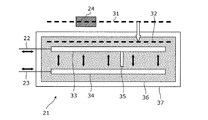
- FIG. 4 is a diagram showing a state in which the battery 21 shown in FIG. 3 is being inspected.
- the battery 21 shown in FIG. 4 includes a pair of electrode terminals 22 and 23, a pair of electrode plates 33 and 34, an electrolyte 36, and a metal package 37.
- the pair of electrode plates 33 and 34 and the electrolyte 36 are covered with a metal package 37.
- the measuring unit 12 measures the magnetic field via the TMR sensor 24 on the scanning target surface 31 above the battery 21 placed on the turntable 25.
- the generation unit 13 acquires information on the magnetic field measured on the scan target surface 31 from the measurement unit 12 and analyzes the acquired information, thereby acquiring information on the magnetic field on the reconstruction target surface 32. Good. That is, the generation unit 13 may acquire information on the magnetic field of the reconstruction target surface 32 based on the information on the magnetic field of the scanning target surface 31.
- Patent Document 2 Methods for analyzing magnetic field information are described in International Publication No. 2008/123432 (hereinafter, Patent Document 2), International Publication No. 2012/153696 (hereinafter, Patent Document 3), and the like. Specifically, Patent Document 2 and Patent Document 3 describe a method of analyzing magnetic field information using Maxwell's equations.
- the generation unit 13 may use a method described in Patent Document 2, Patent Document 3, or the like. Or the measurement part 12 may acquire the information of the magnetic field of the reconstruction object surface 32 using the method as described in patent document 2 or patent document 3. Then, the generation unit 13 may acquire information on the magnetic field of the reconstruction target surface 32 from the measurement unit 12.
- the current flowing inside the battery 21 generates a magnetic field outside the battery 21.
- the measuring unit 12 measures the magnetic field generated by the current flowing inside the battery 21 outside the battery 21. If the current flowing inside the battery 21 changes, the magnetic field outside the battery 21 also changes.
- a dendrite 35 may be formed inside the battery 21 by depositing metal on the electrode plate 33 or the electrode plate 34. That is, in the charging / discharging process of the battery 21, the dendrite 35 may be generated and grow.
- the conductivity of the dendrite 35 is higher than the conductivity of the electrolyte 36. Therefore, if the dendrite 35 is generated inside the battery 21, the electrical state inside the battery 21 changes. Thereby, the magnetic field outside the battery 21 also changes. If the battery inspection apparatus 10 can appropriately measure the magnetic field outside the battery 21, the state of generation and growth of the dendrite 35 can be inspected.
- Observation of the generation and growth of the dendrite 35 accompanying charging / discharging of the battery 21 may be useful for suppressing the generation and growth of the dendrite 35 accompanying charging / discharging of the battery 21.
- the dendrite 35 is generated and grown as the battery 21 is charged / discharged, the electrical state inside the battery 21 changes, and the magnetic field generated outside the battery 21 also changes. It is difficult to properly measure a magnetic field that changes over time.
- the battery inspection device 10 stops charging / discharging of the battery 21 in the charging / discharging process of the battery 21. Thereby, generation
- the current flowing inside the battery 21 by the AC voltage does not promote the generation and growth of the dendrite 35. Therefore, the electrical state inside the battery 21 is stabilized. Further, the current flowing inside the battery 21 by the AC voltage can generate a magnetic field outside the battery 21. In addition, since the electrical state inside the battery 21 is stable, changes in the magnetic field over time are suppressed. Therefore, the battery inspection apparatus 10 can appropriately measure the magnetic field in the charge / discharge process of the battery 21.
- the battery inspection apparatus 10 pauses charging / discharging in the charging / discharging process of the battery 21 and applies an alternating voltage to the battery 21 to suppress the generation and growth of the dendrite 35 and to apply the magnetic field over time. It can be measured appropriately.
- FIG. 5 is a diagram showing a transition of the current flowing in the battery 21 shown in FIG.
- the battery testing device 10 a DC voltage is applied to the battery 21 to the time T 1.
- the battery testing device 10 an AC voltage is applied to the battery 21 from time T 1 to time T 2.
- the battery testing device 10 applies a DC voltage to the battery 21 from the time T 2, until time T 3.
- the battery testing device 10 applies a DC voltage to the battery 21 from time T 4.
- charging of the battery 21 is performed until time T 1.
- the charging of the battery 21 is inhibited from time T 1 to time T 2.
- the charging of the battery 21 is performed from time T 2, until time T 3.
- the charging of the battery 21 is inhibited from time T 3 to time T 4.
- the charging of the battery 21 is performed from time T 4.
- the battery inspection device 10 measures the magnetic field around the battery 21 during the period when the growth of dendrites is stopped. That is, the battery inspection apparatus 10 measures the magnetic field in a state where an AC voltage is applied to the battery 21.
- FIG. 6 is a diagram showing the transition of the storage rate of the battery 21 shown in FIG.
- the example of FIG. 6 corresponds to the example of FIG. In FIG. 6, the storage rate is used on the vertical axis instead of the current.
- the power storage rate increases during the charging period. And in the period when charge is suppressed, the increase in an electrical storage rate is suppressed.
- the battery inspection device 10 can inspect the dendrite growth at a point in the middle of the charging process by measuring the magnetic field in a period in which the increase in the storage rate is suppressed. And the battery test
- inspection apparatus 10 can test
- the battery inspection device 10 may measure the magnetic field in each of the plurality of periods in which the increase in the power storage rate is suppressed, and generate an image indicating the magnetic field distribution or the current distribution based on the measured magnetic field. Good. That is, the battery inspection apparatus 10 may generate a plurality of images corresponding to a plurality of points in the middle of the charging process. And the battery test
- the battery inspection apparatus 10 can perform the same operation as the charging process in the discharging process. That is, the battery inspection apparatus 10 suppresses the discharge of the battery 21 and applies an AC voltage to the battery 21 in the discharge process of the battery 21.
- the battery inspection apparatus 10 can appropriately measure the magnetic field in the discharging process of the battery 21 by measuring the magnetic field in this state.
- FIG. 7 is a diagram showing a circuit for applying an AC voltage to the battery 21 shown in FIG.
- FIG. 7 shows the battery 21 and the application unit 11. Further, a capacitor C b , an electromotive force ⁇ o , an internal resistance ⁇ b , a DC voltage ⁇ e , an AC voltage ⁇ a cos ⁇ t, and an external resistance ⁇ are shown.
- the capacitor C b , the electromotive force ⁇ o , and the internal resistance ⁇ b are included in the battery 21.
- the internal resistance ⁇ b , the DC voltage ⁇ e , and the AC voltage ⁇ a cos ⁇ t are included in the application unit 11.
- AC voltage ⁇ a cos ⁇ t of t represents the time, the ⁇ of the AC voltage ⁇ a cos ⁇ t, shows the angular frequency.
- Is applied to the battery 21 with the external voltage ⁇ E (t) ⁇ e + ⁇ a cos ⁇ t superimposed thereon.
- the external voltage ⁇ E (t) is obtained by an external modulation bias (external modulation circuit and bias circuit).
- the application unit 11 repeats charging and discharging at the angular frequency ⁇ in a state in which the application unit 11 is balanced with respect to the output voltage ⁇ o (T) of the battery 21.
- the measurement unit 12 measures a magnetic field corresponding to a charge / discharge response component repeated at an angular frequency ⁇ .
- the battery 21 has a shielding portion that prevents the current inside the battery 21 from generating a magnetic field outside the battery 21.
- the magnetic field is shielded by the shielding portions such as the electrode plates 33 and 34 and the metal package 37 and does not leak outside the battery 21. .
- the application unit 11 superimposes the AC voltage ⁇ a cos ⁇ t corresponding to a frequency lower than the frequency determined based on the characteristics of the shielding unit on the DC voltage ⁇ e .
- the characteristics of the shielding part are the conductivity of the shielding part, the permeability of the shielding part, and the thickness (depth) of the shielding part.
- the application unit 11 has f ⁇ 1 / ( An alternating voltage ⁇ a cos ⁇ t corresponding to the frequency f satisfying ⁇ d 2 ) is superimposed.
- the thickness d of the shielding part is, for example, the total of the thickness of the electrode plate 33 and the thickness of the metal package 37.
- the application unit 11 may superimpose an AC voltage ⁇ a cos ⁇ t corresponding to a frequency lower than the above-described frequency determined based on the characteristics of the shielding unit and close to the above-described frequency. Thereby, the influence of charging / discharging is suppressed.
- the application unit 11 may superimpose an AC voltage ⁇ a cos ⁇ t corresponding to a frequency lower than the above frequency and higher than 1 ⁇ 2 of the above frequency.
- the application unit 11 may superimpose an AC voltage ⁇ a cos ⁇ t corresponding to the frequency f satisfying 1 / (2 ⁇ d 2 ) ⁇ f ⁇ 1 / ( ⁇ d 2 ).
- some of the conductivity of the shielding part, the magnetic permeability of the shielding part, and the thickness of the shielding part may be used as the characteristics of the shielding part, and other attributes of the shielding part may be used as the characteristics of the shielding part. It may be used.
- the application unit 11 may adjust the frequency of the AC voltage ⁇ a cos ⁇ t to a frequency lower than the frequency determined based on the characteristics of the shielding unit. For example, the application unit 11 adjusts the frequency low so that a magnetic field is generated outside the battery 21, that is, a magnetic field is generated beyond the shielding unit. Further, the application unit 11 may adjust the frequency so that the measurement unit 12 measures a magnetic field equal to or higher than a predetermined reference.
- the application unit 11 stops the superposition of the AC voltage and controls so that only one of charging and discharging is performed. For example, the application unit 11 applies a DC voltage larger than the output voltage of the battery 21 to charge the battery 21. Alternatively, the application unit 11 applies a DC voltage smaller than the output voltage of the battery 21 to discharge the battery 21. Alternatively, the application unit 11 may discharge the battery 21 without applying a voltage.
- the application unit 11 intermittently applies an external voltage in which an AC voltage is superimposed on a DC voltage for balancing the output voltage of the battery 21 in the charge / discharge process.
- the application unit 11 may apply an external voltage on which an alternating voltage is superimposed periodically (periodically) or irregularly.
- the application unit 11 may automatically apply an external voltage on which an alternating voltage is superimposed, or may apply it based on a manual operation.
- the measurement unit 12 measures the magnetic field around the battery 21 in a state where an external voltage on which an alternating voltage is superimposed is applied.
- each time for measuring the magnetic field in the charge / discharge process may be determined in advance.
- the application unit 11 applies an external voltage on which an alternating voltage is superimposed to the battery 21 at each predetermined time in the charge / discharge process.
- the measurement part 12 measures a magnetic field at each predetermined time in the charging / discharging process.
- the application unit 11 controls so that normal charging / discharging is performed. Thereby, the battery test
- Each time for measuring the magnetic field in the charge / discharge process may be determined based on the characteristics of the output voltage of the battery 21 or may be determined based on the characteristics of time. That is, the battery inspection apparatus 10 may measure the magnetic field for each predetermined output voltage, or may measure the magnetic field for each predetermined time interval.
- generation part 13 respond
- the application unit 11 and the measurement unit 12 may be linked using a synchronization signal. That is, the AC voltage superposition and the magnetic field measurement may be controlled to start at the same time and end at the same time by the synchronization signal.
- another processing unit may execute a process executed by a specific processing unit.
- the order in which the processes are executed may be changed, or a plurality of processes may be executed in parallel.
- the battery inspection device may be expressed as a battery inspection system.
- the application unit may be expressed as an application device or an application circuit.
- the measurement unit may be expressed as a measurement device or a measurement circuit.
- the generation unit may be expressed as a generation device or a generation circuit.
- the display unit may be expressed as a display device or a display circuit.
- the present invention can be realized not only as a battery inspection apparatus, but also as a method using a processing means constituting the battery inspection apparatus as a step. For example, these steps are performed by a computer.
- the present invention can be realized as a program for causing a computer to execute the steps included in these methods.
- the present invention can be realized as a non-transitory computer-readable recording medium such as a CD-ROM in which the program is recorded.
- the plurality of components included in the battery inspection device may be realized as an LSI (Large Scale Integration) that is an integrated circuit. These components may be individually made into one chip, or may be made into one chip so as to include a part or all of them. Although referred to here as an LSI, it may be referred to as an IC (Integrated Circuit), a system LSI, a super LSI, or an ultra LSI depending on the degree of integration.
- LSI Large Scale Integration
- the method of circuit integration is not limited to LSI, and implementation with a dedicated circuit or a general-purpose processor is also possible.
- An FPGA Field Programmable Gate Array
- a reconfigurable processor that can reconfigure the connection and setting of circuit cells inside the LSI may be used.
- the battery inspection apparatus and the battery inspection method according to the present invention can be used for battery inspection, and can be used for battery development and improvement.
Landscapes
- Engineering & Computer Science (AREA)
- Manufacturing & Machinery (AREA)
- Chemical & Material Sciences (AREA)
- Chemical Kinetics & Catalysis (AREA)
- Electrochemistry (AREA)
- General Chemical & Material Sciences (AREA)
- Secondary Cells (AREA)
- Tests Of Electric Status Of Batteries (AREA)
- Charge And Discharge Circuits For Batteries Or The Like (AREA)
Abstract
L'invention porte sur un dispositif d'inspection de batterie (10), lequel dispositif d'inspection de batterie comporte : une unité d'application (11), qui, pendant un processus de charge/décharge de la batterie, applique à la batterie une tension externe dans laquelle une tension alternative a été superposée à une tension continue, ladite tension externe servant à équilibrer la tension de sortie de la batterie ; et une unité de mesure (12), qui mesure le champ magnétique à l'extérieur de la batterie quand la tension externe dans laquelle une tension alternative a été superposée à une tension continue a été appliquée à la batterie. La batterie comprend une partie de blindage qui empêche le courant à l'intérieur de la batterie de générer un champ magnétique à l'extérieur de la batterie, et l'unité d'application (11) applique à la batterie une tension externe dans laquelle une tension alternative, qui correspond à une seconde fréquence qui est inférieure à une première fréquence qui est décidée sur la base des caractéristiques de la partie de blindage, a été superposée à une tension continue.
Priority Applications (1)
| Application Number | Priority Date | Filing Date | Title |
|---|---|---|---|
| JP2016507362A JP6461095B2 (ja) | 2014-03-13 | 2015-03-11 | 電池検査装置および電池検査方法 |
Applications Claiming Priority (2)
| Application Number | Priority Date | Filing Date | Title |
|---|---|---|---|
| JP2014-049798 | 2014-03-13 | ||
| JP2014049798 | 2014-03-13 |
Publications (1)
| Publication Number | Publication Date |
|---|---|
| WO2015136930A1 true WO2015136930A1 (fr) | 2015-09-17 |
Family
ID=54071387
Family Applications (1)
| Application Number | Title | Priority Date | Filing Date |
|---|---|---|---|
| PCT/JP2015/001343 Ceased WO2015136930A1 (fr) | 2014-03-13 | 2015-03-11 | Dispositif d'inspection de batterie et procédé d'inspection de batterie |
Country Status (2)
| Country | Link |
|---|---|
| JP (1) | JP6461095B2 (fr) |
| WO (1) | WO2015136930A1 (fr) |
Cited By (5)
| Publication number | Priority date | Publication date | Assignee | Title |
|---|---|---|---|---|
| CN109387564A (zh) * | 2018-08-29 | 2019-02-26 | 中国电力科学研究院有限公司 | 一种基于锂枝晶生长的锂离子电池在线检测方法及装置 |
| JP2019184296A (ja) * | 2018-04-04 | 2019-10-24 | スミダコーポレーション株式会社 | 微小電流検知装置 |
| CN113253135A (zh) * | 2021-05-11 | 2021-08-13 | 吉林大学 | 一种电池原位测试系统 |
| JPWO2024009894A1 (fr) * | 2022-07-07 | 2024-01-11 | ||
| WO2025004516A1 (fr) * | 2023-06-26 | 2025-01-02 | 株式会社 Integral Geometry Science | Dispositif d'inspection de batterie de stockage et procédé d'inspection de batterie de stockage |
Citations (4)
| Publication number | Priority date | Publication date | Assignee | Title |
|---|---|---|---|---|
| JP2001280249A (ja) * | 2000-03-31 | 2001-10-10 | Matsushita Electric Ind Co Ltd | 圧縮機および電動機 |
| JP2010080395A (ja) * | 2008-09-29 | 2010-04-08 | Panasonic Corp | リチウムイオン二次電池用電極板及びリチウムイオン二次電池 |
| JP2013032985A (ja) * | 2011-08-02 | 2013-02-14 | Pulstec Industrial Co Ltd | 2次電池の評価装置及び評価方法 |
| JP2013054984A (ja) * | 2011-09-06 | 2013-03-21 | Hitachi Ltd | 磁気計測装置および磁気計測方法 |
Family Cites Families (1)
| Publication number | Priority date | Publication date | Assignee | Title |
|---|---|---|---|---|
| US9184611B2 (en) * | 2011-10-10 | 2015-11-10 | Villanova University | Method and system for magnetic field probing for sealed-acid battery diagnosis |
-
2015
- 2015-03-11 WO PCT/JP2015/001343 patent/WO2015136930A1/fr not_active Ceased
- 2015-03-11 JP JP2016507362A patent/JP6461095B2/ja active Active
Patent Citations (4)
| Publication number | Priority date | Publication date | Assignee | Title |
|---|---|---|---|---|
| JP2001280249A (ja) * | 2000-03-31 | 2001-10-10 | Matsushita Electric Ind Co Ltd | 圧縮機および電動機 |
| JP2010080395A (ja) * | 2008-09-29 | 2010-04-08 | Panasonic Corp | リチウムイオン二次電池用電極板及びリチウムイオン二次電池 |
| JP2013032985A (ja) * | 2011-08-02 | 2013-02-14 | Pulstec Industrial Co Ltd | 2次電池の評価装置及び評価方法 |
| JP2013054984A (ja) * | 2011-09-06 | 2013-03-21 | Hitachi Ltd | 磁気計測装置および磁気計測方法 |
Cited By (10)
| Publication number | Priority date | Publication date | Assignee | Title |
|---|---|---|---|---|
| JP2019184296A (ja) * | 2018-04-04 | 2019-10-24 | スミダコーポレーション株式会社 | 微小電流検知装置 |
| JP7396787B2 (ja) | 2018-04-04 | 2023-12-12 | スミダコーポレーション株式会社 | 微小電流検出装置および微小電流検出方法 |
| CN109387564A (zh) * | 2018-08-29 | 2019-02-26 | 中国电力科学研究院有限公司 | 一种基于锂枝晶生长的锂离子电池在线检测方法及装置 |
| CN109387564B (zh) * | 2018-08-29 | 2023-07-21 | 中国电力科学研究院有限公司 | 一种基于锂枝晶生长的锂离子电池在线检测方法及装置 |
| CN113253135A (zh) * | 2021-05-11 | 2021-08-13 | 吉林大学 | 一种电池原位测试系统 |
| JPWO2024009894A1 (fr) * | 2022-07-07 | 2024-01-11 | ||
| WO2024009894A1 (fr) | 2022-07-07 | 2024-01-11 | 株式会社 Integral Geometry Science | Dispositif et procédé de mesure |
| KR20240110827A (ko) | 2022-07-07 | 2024-07-16 | 가부시키가이샤 인테그랄 지오메트리 사이언스 | 측정 장치 및 측정 방법 |
| JP7616735B2 (ja) | 2022-07-07 | 2025-01-17 | 株式会社 Integral Geometry Science | 測定装置および測定方法 |
| WO2025004516A1 (fr) * | 2023-06-26 | 2025-01-02 | 株式会社 Integral Geometry Science | Dispositif d'inspection de batterie de stockage et procédé d'inspection de batterie de stockage |
Also Published As
| Publication number | Publication date |
|---|---|
| JPWO2015136930A1 (ja) | 2017-04-06 |
| JP6461095B2 (ja) | 2019-01-30 |
Similar Documents
| Publication | Publication Date | Title |
|---|---|---|
| JP6461095B2 (ja) | 電池検査装置および電池検査方法 | |
| Oldenburger et al. | Investigation of the low frequency Warburg impedance of Li-ion cells by frequency domain measurements | |
| WO2021024859A1 (fr) | Dispositif et procédé d'inspection de batterie d'accumulateurs | |
| US20220357402A1 (en) | Battery characterisation and monitoring system | |
| JP6616987B2 (ja) | インピーダンス測定装置およびインピーダンス測定方法 | |
| US12352711B2 (en) | System and method for magnetic resonance mapping of physical and chemical changes in conducting structures | |
| CN106133515A (zh) | 检查探头、检查系统以及检查方法 | |
| CN104126117A (zh) | 涡流探伤方法以及装置 | |
| JP7616735B2 (ja) | 測定装置および測定方法 | |
| JP7312442B2 (ja) | 検査装置および検査方法 | |
| US11125832B2 (en) | Multi-phase simulation environment | |
| CN107656235A (zh) | 一种计量芯片基准电压的测量装置及方法 | |
| US9268000B2 (en) | System and method for improved accuracy in battery resistance measurement systems | |
| KR100448840B1 (ko) | 2차 전지 테스트용 다채널 임피던스 측정 장치 | |
| CN117330971A (zh) | 新能源设备的检测方法、装置及检测设备 | |
| CN109239607A (zh) | 电池检测方法、系统及电池分析装置 | |
| JP2012211883A (ja) | 測定装置、信号測定方法 | |
| JP2016219272A (ja) | 二次電池の検査方法 | |
| KR20260027885A (ko) | 축전지 검사 장치 및 축전지 검사 방법 | |
| CN104049148B (zh) | 用于电池电阻测量系统的改进的精度的系统和方法 | |
| RU2418302C1 (ru) | Устройство диагностики кабелей | |
| Melo et al. | Development and Validation of a Magnetic Sensor Array for Battery Diagnostics | |
| JP6320862B2 (ja) | 検査装置および検査方法 | |
| JP2024147617A (ja) | インピーダンス測定装置、測定方法および二次電池診断システム | |
| Rodrigues | Development of a miniaturized electrical conductivity gauge based on eddy currents testing |
Legal Events
| Date | Code | Title | Description |
|---|---|---|---|
| 121 | Ep: the epo has been informed by wipo that ep was designated in this application |
Ref document number: 15761511 Country of ref document: EP Kind code of ref document: A1 |
|
| ENP | Entry into the national phase |
Ref document number: 2016507362 Country of ref document: JP Kind code of ref document: A |
|
| NENP | Non-entry into the national phase |
Ref country code: DE |
|
| 122 | Ep: pct application non-entry in european phase |
Ref document number: 15761511 Country of ref document: EP Kind code of ref document: A1 |