WO2015136971A1 - 制御システム - Google Patents
制御システム Download PDFInfo
- Publication number
- WO2015136971A1 WO2015136971A1 PCT/JP2015/050944 JP2015050944W WO2015136971A1 WO 2015136971 A1 WO2015136971 A1 WO 2015136971A1 JP 2015050944 W JP2015050944 W JP 2015050944W WO 2015136971 A1 WO2015136971 A1 WO 2015136971A1
- Authority
- WO
- WIPO (PCT)
- Prior art keywords
- output
- time
- input
- sampling
- unit
- Prior art date
- Legal status (The legal status is an assumption and is not a legal conclusion. Google has not performed a legal analysis and makes no representation as to the accuracy of the status listed.)
- Ceased
Links
Images

Classifications
-
- G—PHYSICS
- G05—CONTROLLING; REGULATING
- G05B—CONTROL OR REGULATING SYSTEMS IN GENERAL; FUNCTIONAL ELEMENTS OF SUCH SYSTEMS; MONITORING OR TESTING ARRANGEMENTS FOR SUCH SYSTEMS OR ELEMENTS
- G05B19/00—Program-control systems
- G05B19/02—Program-control systems electric
- G05B19/04—Program control other than numerical control, i.e. in sequence controllers or logic controllers
- G05B19/05—Programmable logic controllers, e.g. simulating logic interconnections of signals according to ladder diagrams or function charts
- G05B19/056—Programming the PLC
-
- G—PHYSICS
- G05—CONTROLLING; REGULATING
- G05B—CONTROL OR REGULATING SYSTEMS IN GENERAL; FUNCTIONAL ELEMENTS OF SUCH SYSTEMS; MONITORING OR TESTING ARRANGEMENTS FOR SUCH SYSTEMS OR ELEMENTS
- G05B19/00—Program-control systems
- G05B19/02—Program-control systems electric
- G05B19/04—Program control other than numerical control, i.e. in sequence controllers or logic controllers
- G05B19/05—Programmable logic controllers, e.g. simulating logic interconnections of signals according to ladder diagrams or function charts
- G05B19/054—Input/output
-
- G—PHYSICS
- G05—CONTROLLING; REGULATING
- G05B—CONTROL OR REGULATING SYSTEMS IN GENERAL; FUNCTIONAL ELEMENTS OF SUCH SYSTEMS; MONITORING OR TESTING ARRANGEMENTS FOR SUCH SYSTEMS OR ELEMENTS
- G05B2219/00—Program-control systems
- G05B2219/10—Plc systems
- G05B2219/15—Plc structure of the system
- G05B2219/15115—Pc serves as plc, programming panel, monitoring panel
-
- G—PHYSICS
- G05—CONTROLLING; REGULATING
- G05B—CONTROL OR REGULATING SYSTEMS IN GENERAL; FUNCTIONAL ELEMENTS OF SUCH SYSTEMS; MONITORING OR TESTING ARRANGEMENTS FOR SUCH SYSTEMS OR ELEMENTS
- G05B2219/00—Program-control systems
- G05B2219/30—Nc systems
- G05B2219/34—Director, elements to supervisory
- G05B2219/34269—Programmable computer controller, plc implemented with pc
-
- G—PHYSICS
- G05—CONTROLLING; REGULATING
- G05B—CONTROL OR REGULATING SYSTEMS IN GENERAL; FUNCTIONAL ELEMENTS OF SUCH SYSTEMS; MONITORING OR TESTING ARRANGEMENTS FOR SUCH SYSTEMS OR ELEMENTS
- G05B2219/00—Program-control systems
- G05B2219/30—Nc systems
- G05B2219/34—Director, elements to supervisory
- G05B2219/34301—Nc system has direct access to I-O of pic, plc
Definitions
- the present invention relates to a control system capable of sampling input / output signals and internal variables.
- a control device that calculates and outputs an output signal based on an external input signal and controls a control target device by executing a task including a user program at a predetermined cycle.
- a function for tracking temporal changes in the input signal and output signal (input / output signal) is known.
- Patent Document 1 discloses a control device that collects variables that are referred to and updated in a user program when a task including the user program is executed.
- the tracing function of the conventional control device is used inside the control device, and acquires the input / output signal by sampling a variable associated with the input / output signal.
- the actual input signal input to the control device and the actual output signal output from the control device are sampled separately from the trace function. Therefore, the data obtained by the trace function is compared with the actual input signal and output signal sampling results (sampling data), the change of the variables used in the control device, the actual input signal and output It was difficult to compare with the signal.
- the control device when it is difficult to compare the variables used in the control device with the actual input signal and output signal, the control device, the device for acquiring the input signal (for example, the input unit), and The efficiency of adjustment of a device (for example, an output unit) that outputs an output signal is lowered.
- a device for example, an output unit
- An object of the present invention is to facilitate device adjustment in a control system.
- a control system includes a PLC system and a development support apparatus.
- the PLC system has an input unit, an output unit, and a control device.
- the input unit obtains actual sampling data stored in association with the first sampling value and the first sampling time.
- the first sampling value is a value obtained by sampling the input signal at the first timing.
- the first sampling time is the time when the input signal is sampled.
- the output unit outputs an output signal based on output instruction data including an output instruction time and an instruction output signal value.
- the instruction output signal value is an output signal value to be output at the output instruction time.
- the control device has a task execution unit and a sampling unit.
- the task execution unit repeatedly executes a task including an I / O refresh process and a user program execution process at a predetermined cycle.
- the I / O refresh process is a process of updating the value of the input variable associated with the input signal based on the input signal and updating the output signal based on the output variable associated with the output signal.
- the user program execution process calculates the value of the output variable by executing the user program based on the input variable, calculates the output instruction time and the instruction output signal value based on the value of the output variable, and outputs the output instruction data This is a process to send to the output unit.
- the sampling unit acquires variable sampling data that stores the second sampling value and the second sampling time in association with each other.
- the second sampling value is a value obtained by sampling the input variable, the output variable, and / or the internal variable at the second timing.
- the internal variable is a variable used in the user program.
- the second sampling time is a time at which the input variable, the output variable, and / or the internal variable is sampled.
- the development support apparatus includes an identical time series data creation unit and an identical time series data display unit.
- the temporary series data creation unit creates the same time series data.
- the first sampling time, the second sampling time, and the output instruction time are arranged on the same time series, and the first sampling value, the second sampling value, and the instruction output signal value are respectively the first time series data.
- This data is stored in association with the time on the same time series corresponding to the sampling time, the second sampling time, and the output instruction time.
- the same time series data display unit displays the same time series data on the same time axis.
- the input unit samples the input signal at the first timing to obtain the first sampling value, and samples the time when the input signal is sampled as the first sampling time.
- the actual sampling data is acquired by associating and storing one sampling time.
- a value obtained by sampling the input variable, the output variable, and / or the internal variable at the second timing by the sampling unit of the control device is set as the second sampling value, and the time when the variable is sampled is set to the second time. Sampling is performed as the sampling time, and the second sampling time and the second sampling time are stored in association with each other to obtain variable sampling data.
- the user program calculates the value of the output variable based on the input variable, the output instruction time and the output instruction based on the value of the output variable An instruction output signal value to be output at the time is calculated, and output instruction data including the output instruction time and the instruction output signal value is transmitted to the output unit.
- the same time series data creation unit arranges the first sampling time, the second sampling time, and the output instruction time on the same time series, and the first sampling value, the second sampling value, and the instruction output signal.
- the values are stored in association with the times on the same time series corresponding to the first sampling time, the second sampling time, and the output instruction time, respectively, and the same time series data is created.
- the same time series data display unit displays the same time series data.
- the actual sampling data, the variable sampling data, and the output instruction data are collected on the same time series to create one identical time series data.
- the same time series data is displayed on the same time axis. Thereby, the relationship between the sampling result and the instruction output signal value can be confirmed on the same time axis without going through a procedure for organizing individual data. As a result, the apparatus can be easily adjusted without imposing a heavy burden on the system developer.
- the input unit may include a high-speed sampling input unit.
- the high-speed sampling input unit is an input unit that samples a first sampling value every high-speed sampling cycle shorter than a predetermined cycle in which a task is executed, and uses a time determined by the high-speed sampling cycle as a first sampling time. As a result, the input signal can be sampled with higher accuracy in a cycle shorter than a predetermined cycle that is a task execution cycle.
- the input unit may include a change time acquisition input unit.
- the change time acquisition input unit uses the timing at which the input signal has changed a predetermined time as the first timing, the signal value of the input signal after the predetermined change as the first sampling value, and the time determined by the first timing. This is an input unit for the first sampling time. Thereby, it is possible to accurately sample the time at which the input signal has changed a predetermined time together with the input signal value at the time of the change, without being bound by the task execution cycle (predetermined cycle).
- the input unit may input an input signal at the specified input instruction time. Thereby, an input signal can be input without being restricted by the task execution period (predetermined period).
- the input unit may input an input signal with a time determined by a high-speed input cycle shorter than a predetermined cycle as an input instruction time.
- an input signal can be input at a higher speed than the task execution cycle without being restricted by the task execution cycle (predetermined cycle).
- the output unit may include a high-speed output unit.
- the high-speed output unit outputs an output signal using a time determined by a high-speed output cycle shorter than a predetermined cycle in which a task is executed as an output instruction time, and a signal value to be output every high-speed output cycle as an instruction output signal value. It is an output unit.
- the output signal can be controlled and output more finely in a cycle shorter than the predetermined cycle without being bound by the task execution cycle (predetermined cycle).
- the output unit may include a time designation output unit.
- the time designation output unit is an output unit that outputs an output signal using a predetermined time as an output instruction time and a signal value to be output at a predetermined time as an instruction output signal value.
- an output signal having an arbitrary signal value can be output at an arbitrary predetermined time without being bound by the task execution period (predetermined period).
- the above control system may further include a common time counting unit.
- the common time counting unit counts the first sampling time, the second sampling time, and the output instruction time at the common time.
- the output unit may store the sampling output signal value obtained by sampling the output signal at a predetermined timing and the output sampling time determined by the predetermined timing in the actual sampling data. Thereby, an actual output signal can be sampled.
- the time series data creation unit further arranges output sampling times on the same time series and creates the same time series data by storing the sampling output signal value in association with the time on the same time series corresponding to the output sampling time. May be. Thereby, the sampling result of the actual output signal can be displayed on the same time axis.
- a control system includes a PLC system and a development support apparatus.
- the PLC system includes an input unit, an output unit, and a control device.
- the input unit inputs an input signal.
- the output signal outputs an output signal.
- the control device has a task execution unit and a sampling unit.
- the task execution unit repeatedly executes a task including an I / O refresh process and a user program execution process at a predetermined cycle.
- the I / O refresh process is a process of updating the value of the input variable associated with the input signal based on the input signal and updating the output signal based on the value of the output variable associated with the output signal.
- the user program execution process is a process for calculating the value of the output variable by executing the user program based on the input variable.
- the sampling unit acquires variable sampling data that stores the second sampling value and the second sampling time in association with each other.
- the second sampling value is a value obtained by sampling the input variable, the output variable, and / or the internal variable at the second timing.
- the internal variable is a variable used in the user program.
- the second sampling time is a time at which the input variable, the output variable, and / or the internal variable is sampled.
- the development support apparatus includes an input / output change time prediction unit, a predicted input / output signal generation unit, and an identical time series data display unit.
- the input / output change time prediction unit performs predetermined operations in the input change time and / or output change time, the connection relationship between the input unit and / or output unit and the control device, the communication speed, and the input unit and / or output unit. Prediction is based on the operating speed and the second sampling time.
- the input change time is a time when the signal value of the input signal becomes a value corresponding to the value of the input variable at the second sampling time.
- the output change time is a time at which the signal value of the output signal becomes a value corresponding to the value of the output variable at the second sampling time.
- the predicted input / output signal generation unit generates predicted input signal data and / or predicted output signal data.
- the predicted input signal data is data generated by associating the value of the input variable at the second sampling time with the input change time.
- the predicted output signal data is data generated by associating the value of the output variable at the second sampling time with the output change time.
- the temporary series data display unit displays variable sampling data, predicted input signal data, and / or predicted output signal data on the same time axis.
- the sampling unit samples the input variable, the output variable, and / or the internal variable at the second timing to obtain the second sampling, and the input variable, the output variable, and / or the internal variable. Is sampled as the second sampling time, and variable sampling data is acquired.
- the input / output change time prediction unit is configured to input a change time and / or an output signal that is a time when the signal value of the input signal becomes a value corresponding to the value of the input variable at the second sampling time.
- the output change time which is the time when the signal value becomes a value corresponding to the value of the output variable at the second sampling time, is connected to the input unit and / or the output unit and the control device, the communication speed, the input unit and / or the output. Prediction is based on the operating speed at which the unit performs a predetermined operation and the second sampling time.
- the predicted input / output signal generation unit creates predicted input signal data by associating the input change time with the value of the input variable at the second sampling time, and associates the output change time with the value of the output variable at the second sampling time. Create predicted output signal data. Further, the same time series data display unit displays the variable sampling data, the predicted input signal data, and / or the predicted output signal data on the same time axis.
- the apparatus can be easily adjusted without imposing a heavy burden on the system developer.
- the development support device may further include an input / output time adjustment unit.
- the input / output time adjustment unit adjusts the input change time and / or the output change time. Thereby, the time when the input signal is input (input change time) and the time when the output signal is output (output change time) can be adjusted for each input unit and output unit. As a result, the apparatus can be adjusted more precisely and finely in the control system.
- the output unit may output an output signal based on output instruction data including an output instruction time and an instruction output signal value to be output at the output instruction time. Thereby, an output signal can be output without being restricted by the task execution cycle (predetermined cycle).
- the output instruction time may be the output change time, and the instruction output signal may be the value of the output variable at the second sampling time. Thereby, the output change time adjusted in the input / output time adjustment unit can be reflected in the output unit.
- the input instruction time may be an input change time. Thereby, the input change time adjusted in the input / output time adjustment unit can be reflected in the input unit.
- Equipment can be easily adjusted in the control system.
- the figure which shows the whole structure of a control system The figure which shows the input unit and output unit which are arrange
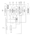
- FIG. 1 is a diagram illustrating an overall configuration of a control system.
- the control system 100 includes a PLC system 1 and a development support device 3.
- the PLC system 1 inputs a signal from a signal input unit 5 configured by, for example, a sensor or a switch.
- the PLC system 1 calculates an output signal for controlling the control target device 7 by executing a program (user program 1131) using an input signal from a signal input unit 5 (described later) as necessary.
- the development support apparatus 3 realizes various functions for creating a user program 1131 (FIG. 4) executed in the control apparatus 11 of the PLC system 1.
- the number of development support apparatuses 3 that can be connected to the PLC system 1 is not limited to one.
- any number of development support apparatuses 3 can be connected as long as the number of addresses that can be allocated to the development support apparatus 3 permits.
- the detailed structure of the PLC system 1, the control apparatus 11, and the development assistance apparatus 3 is each demonstrated.
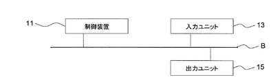
- the PLC system 1 includes a control device 11, an input unit 13, an output unit 15, and a power supply unit 17.
- the control device 11 is a CPU unit of a programmable logic controller (PLC).
- PLC programmable logic controller
- an input signal input to the input unit 13 (described later) is associated with an input variable used in the control device 11.
- an output signal to the output unit 15 (described later) is associated with an output variable used inside the control device 11.
- a predetermined task is repeatedly executed at a predetermined cycle.
- the tasks are an I / O refresh process for updating an input variable based on an input signal from the input unit 13 and an output signal to be output to the output unit 15 based on an output variable, a user program 1131, / Or a processing unit including processing for executing a system program 115a (described later).
- the user program 1131 executed in the control device 11 calculates the output variable using the input variable and, if necessary, the internal variable. Therefore, when the task is repeatedly executed at a predetermined cycle, the input signal, the output signal (input / output signal), and the variables including the input variable, the output variable, and the internal variable change with time. Further, during the user program execution process, the user program 1131 creates output instruction data (described later) using the output variables.
- the output instruction data is data instructing what output signal value is output at which timing in the output unit 15 (described later).
- the control device 11 determines the input variable value and the output variable value associated with the input / output signal, and the internal variable value. It has a function (trace function) for tracking temporal changes by sampling and storing the above variables.
- the input unit 13 inputs an input signal from the signal input unit 5 such as a sensor or a switch, and outputs the input signal to the control device 11.
- an input unit corresponding to the type of signal input from the signal input unit 5 can be used.
- the signal input unit 5 is configured by a thermocouple that measures temperature
- an input unit that uses a voltage generated in the thermocouple as an input signal can be used as the input unit 13.
- the signal input unit 5 is configured by an electrical switch
- an input unit that uses the ON / OFF state of the switch as an input signal can be used as the input unit 13.
- the input unit 13 has a function of sampling not only the input signal but also the input signal. Thereby, in the input unit 13, the temporal change of the actual input signal in the input unit 13 can be sampled. Details of the configuration of the input unit 13 will be described later.
- the input unit 13 can input an input signal at an instructed time (input instruction time). Thereby, an input signal can be input without being restricted by the task execution period (predetermined period).
- the output unit 15 outputs an output signal associated with the output variable of the control device 11 to the corresponding control target device 7. Thereby, the control apparatus 11 can control the control object apparatus 7 based on the output variable calculated by running a program. Further, the output unit 15 outputs an output signal of the signal value (instruction output signal value) designated at the time designated in the output instruction data transmitted from the control device 11 (output instruction time). Thereby, an output signal can be output without being restricted by the task execution cycle (predetermined cycle).
- the output unit 15 can be configured as an output unit corresponding to the type of output signal.
- an output unit having a motion controller function can be used.
- an output unit that outputs a signal for controlling a relay that controls the electric furnace for example, a signal for controlling an ON / OFF duty ratio
- the output unit 15 may have a function of sampling not only the output signal but also the output signal. Thereby, in the output unit 15, the temporal change of the actual output signal in the output unit 15 can be sampled. Details of the configuration of the output unit 15 will be described later.
- the power supply unit 17 supplies power to the control device 11, the input unit 13, and the output unit 15.
- the PLC system 1 may be a system in which all of the above-described components are incorporated in one housing, or each component is incorporated in an individual housing and connected to the components to form a PLC system. Also good.
- the PLC system 1 can connect a desired number of desired control target devices and signal input units.
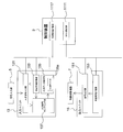
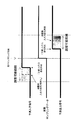
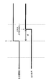
- FIG. 2A is a diagram showing an input unit and an output unit arranged on the I / O bus.
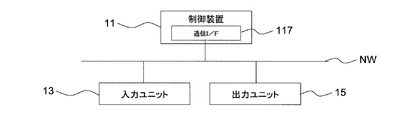
- FIG. 2B is a diagram showing the input unit and the output unit 15 connected to the control device by the communication network.
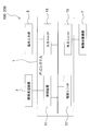
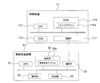
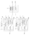
- FIG. 3 is a diagram illustrating the configuration of the control device and the development support device.
- FIG. 4 is a diagram illustrating a detailed configuration of the control device.
- the control device 11 is a CPU unit in the PLC system.
- the control device 11 provides a CPU 111 that performs arithmetic processing such as execution of a program, a RAM 113 that provides a storage area that can be written and read, and a storage area that is mainly intended for reading.
- ROM 115 to be used, and development support device 3 and / or communication interface 117 for performing data communication with input unit 13 and output unit 15.
- the communication interface 117 performs data transmission / reception using a data communication protocol such as TCP / IP (Transmission Control Protocol / Internet Protocol).
- a data communication protocol such as TCP / IP (Transmission Control Protocol / Internet Protocol).
- achieves the various functions of the control apparatus 11 is demonstrated in more detail using FIG.
- the function of each part of the control device 11 described below is realized by executing the system program 115a stored in the ROM 115 in the CPU 111 of the control device 11 shown in FIG.
- the control device 11 includes a task execution unit 1111, a sampling unit 1113, a common time counting unit 1117, and a transmission / reception unit 1119.
- the task execution unit 1111 refers to the user program 1131 stored in the RAM 113 and repeatedly executes a predetermined task including the execution process of the user program 1131 and the I / O refresh process in a predetermined cycle.
- input signal data 135a (described later) (in some cases, output signal data 155a) sampled in the input unit 13 (also the output unit 15 in some cases) 13 (and output unit 15) to control device 11.
- the task execution unit 1111 executes the task, to the input variable value associated with the input signal based on the input signal input from the input unit 13 and the output signal calculated by the execution of the user program 1131.
- the value of the associated output variable and, if necessary, the value of the internal variable used in the user program 1131 are stored in the variable storage area 1135 secured in a part of the storage area of the RAM 113.
- variable storage area 1135 when the input variable is updated based on the input signal from the input unit 13 and / or by executing the user program 1131 by repeatedly executing the above task at a predetermined cycle, and / or When the internal variables are updated, these updated variable values are stored in the variable storage area 1135.
- the user program 1131 determines the output instruction time and the instruction output signal value based on the value of the output variable stored in the variable storage area 1135. Is calculated and output instruction data is created. Then, the user program 1131 transmits the created output instruction data to the output unit 15.
- the user program 1131 creates output instruction data corresponding to the type of the output unit 15.
- Output instruction data for the high-speed output unit 15 can be created as follows. For example, the output instruction time is determined by dividing a task execution cycle (predetermined cycle) by a predetermined number and dividing it. Specifically, for example, when a predetermined period is divided into n, the first output instruction time is set to a predetermined period / n, the next output instruction time is set to 2 ⁇ (predetermined period / n), and so on. N output instruction times are generated.
- the instruction output signal value at each output instruction time can be calculated by linearly complementing the output variable value at the previous task execution and the output variable value at the current task execution.
- the output instruction data for the time designation output unit 15 includes, for example, an output variable value at the time of executing the current task as an instruction output signal value, and a time at which the instruction output signal value is desired to be output Can be created.
- the user program 1131 calculates the input instruction time and transmits it to the input unit 13. At this time, the user program 1131 calculates an input instruction time according to the type of the input unit 13.
- the input instruction time for the high-speed input unit 13 (described later) and the high-speed sampling input unit 13 (described later) is determined by dividing a task execution cycle (predetermined cycle) by a predetermined number and dividing it. Is the input instruction time. Specifically, for example, when a predetermined period is divided into n, the first input instruction time is set to a predetermined period / n, the next input instruction time is set to 2 ⁇ (predetermined period / n), and so on. N input instruction times are calculated.
- the input instruction time for the time designation input unit 13 is the time when the input signal is desired to be input.
- the input instruction value for which the change time is desired to be acquired is designated as the input instruction time.
- the sampling unit 1113 samples the input variable, the output variable, and / or the internal variable at the second timing.
- the sampling unit 1113 associates the value of the sampled variable (second sampling value) with the second sampling time that is the time when the input variable, the output variable, and / or the internal variable is sampled, and the variable sampling data 1137a. To remember.
- the sampling unit 1113 acquires the variable value of the input variable, the output variable, and / or the internal variable stored in the variable storage area 1135 at the second timing, and sets it as the second sampling value. .
- the sampling unit 1113 sets the time at which the variable value is acquired from the variable storage area 1135 as the second sampling time.
- the sampling unit 1113 uses the common time counted by the common time counting unit 1117 (described later) when the variable is sampled as the second sampling time. Thereby, the relationship between the temporal change of the input / output signal and the temporal change of the variable can be compared more accurately.
- sampling unit 1113 associates the acquired second sampling value with the second sampling time, and stores them in the sampling data storage area 1137 in which an area is secured in the RAM 113.
- variable sampling data 1137a configured by the time sequence of the second sampling time and the sampling value sequence of the second sampling value is acquired.
- the second timing is every predetermined cycle in which the task is executed.
- the second timing is not limited to this, and may be a desired timing such as a timing at which a predetermined trigger is generated or a timing specified in the user program 1131.
- sampling unit 1113 uses the input signal data 135a (output signal data 155a) transmitted from the input unit 13 (output unit 15) as the actual sampling data 1137b when the I / O refresh process is executed. 1137.
- the common time counting unit 1117 counts the common time.
- the input unit 13 and the output unit 15 also have common time counting units 133 and 153 (FIG. 6A) having the same function as the common time counting unit 1117, and the common time counting unit of the control device 11.
- 1117, the common time counting unit 133 (FIG. 6A) in the input unit 13, and the common time counting unit 153 (FIG. 6A) in the output unit are synchronized with each other.
- time is counted at the same time (common time).
- the difference between the time counted in the control device 11, the time counted in the input unit 13, and the count in the output unit 15 is reduced.
- the transmission / reception unit 1119 transmits / receives data to / from the development support apparatus 3 using the communication interface 117.
- the transmission / reception unit 1119 transmits and receives data to and from the input unit 13 and the output unit 15.
- control device 11 of the present embodiment includes the above-described components, the control device 11 includes an input variable associated with the input signal and an output variable associated with the output signal that are used internally.
- the internal variables used in the user program 1131 can be sampled at the second timing.
- the sampling results of the input signal and the output signal in the input unit 13 and the output unit 15 can be held in the control device 11.
- the actual sampling data 1137b can be output to the development support apparatus 3.
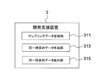
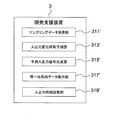
- FIG. 5 is a diagram illustrating a detailed configuration of the development support apparatus.
- the development support apparatus 3 is a computer such as a personal computer, for example. Therefore, as shown in FIG. 3, the development support apparatus 3 includes a CPU 31 that performs arithmetic processing such as program execution, a storage unit 33 that provides a storage area, and an operation configured by input means such as a keyboard and a mouse.
- a communication interface 37 that communicates with the control unit 11, and a display unit 39 that displays a trace result and the like.
- the development support apparatus 3 includes a sampling data receiving unit 311, an identical time series data creation unit 313, and an identical time series data display unit 315.
- the sampling data receiving unit 311 receives the variable sampling data 1137 a and the actual sampling data 1137 b stored in the sampling data storage area 1137 from the control device 11 connected to the communication interface 37, and the storage unit 33 of the development support device 3. To remember.
- the same time series data creation unit 313 creates the same time series data.
- the temporary series data includes a sampling value in the variable sampling data 1137a, a first sampling value in the actual sampling data 1137b, and an instruction output signal value in the output instruction data (or a sampling output signal value of the actual sampling data 1137b).
- the same time series data includes a first sampling time (described later), a second sampling time, and an output instruction time (or output sampling time) arranged on the same time series, and a first sampling value (described later).
- the second sampling value, and the instruction output signal value (or the sampling output signal value) correspond to the first sampling time, the second sampling time, and the output instruction time (or output sampling time), respectively. Data stored in association with the above time.
- the actual sampling data 1137b, the variable sampling data 1137a, and the output instruction data are collected on the same time series, and one identical time series data can be created.
- the same time series data display unit 315 displays the same time series data on the same time axis. Specifically, the same time series data display unit 315 displays the same time series data as a graph of time-sampling value coordinates. As a result, the relationship between the sampling result and the instruction output signal value can be represented on the same time axis without going through the procedure of organizing individual data (actual sampling data 1137b, variable sampling data 1137a, and output instruction data). Can be confirmed. As a result, each device in the control system 100 can be easily adjusted without imposing a heavy burden on the system developer or the like.
- FIG. 6A is a diagram illustrating a configuration of an input unit and an output unit.
- FIG. 6B is a diagram illustrating a configuration of an input unit and an output unit having a sampling function.
- the input unit 13 has an input signal input unit 131, a common time counting unit 133, an input data storage unit 135, and an input signal sampling unit 137.
- the input signal input unit 131 is connected to the signal input unit 5 and inputs an input signal from the signal input unit 5.
- the input signal input unit 131 transmits the input signal to the control device 11 when the task execution unit 1111 of the control device 11 executes the I / O refresh process. As a result, the control device 11 can reflect the value of the input signal input to the input variable during the I / O refresh process.
- the input signal input unit 131 can input an input signal at the specified input instruction time. Thereby, an input signal can be input without being restricted by the task execution period (predetermined period).
- the input signal input unit 131 can input an input signal at an instructed time by one of the following two methods.
- the first is a method of inputting an input signal with a time determined by a high-speed input cycle shorter than a predetermined cycle as an input instruction time.
- an input signal can be input faster than the task execution cycle.
- An input unit that inputs an input signal by this method is referred to as a “high-speed input unit”.
- the second is a method in which a predetermined time is used as the input instruction time.
- an input signal can be input at a designated arbitrary time.
- An input unit that inputs an input signal by this method is referred to as a “time designation input unit”.
- an input signal can be input at a higher speed than the task execution cycle without being restricted by the task execution cycle (predetermined cycle).
- the common time counting unit 133 counts the common time.
- the common time counting unit 133 is synchronized with a common time counting unit 1117 of the control device 11 and a common time counting unit 153 (described later) of the output unit, and the control device 11, the input unit 13, and the output unit 15. Can share the same time (common time).
- the input data storage unit 135 stores the input signal data 135a.
- the input signal data 135 a stored in the input data storage unit 135 is transmitted to the control device 11 when the control device 11 performs an I / O refresh process.
- the input signal sampling unit 137 samples the input signal at the input signal acquisition timing (an example of the first timing) to obtain an input signal sampling value (an example of the first sampling value). Further, the input signal sampling unit 137 sets the time when the input signal sampling value is sampled as the input signal sampling time (an example of the first sampling time). Here, the input signal sampling time is acquired at the common time counted by the common time counting unit 133.
- the input signal sampling unit 137 transmits the input signal sampling value and the input signal sampling time to the input data storage unit 135.
- the transmitted input signal sampling value and input signal sampling time are associated with each other and stored in the input signal data 135a.
- the input signal sampling unit 137 samples the input signal by one of the following two methods.
- the first method is to sample the input signal sampling value every cycle (high-speed sampling cycle) shorter than a predetermined cycle in which the task is executed, and to sample the time determined by the high-speed sampling cycle as the input signal sampling time (high-speed sampling). Method).
- An input unit that samples an input signal at a cycle shorter than a predetermined cycle in this way is referred to as a “high-speed sampling input unit”.
- the input signal acquisition timing is the timing when the input signal has changed a predetermined amount
- the signal value of the input signal after the predetermined change is the input signal sampling value
- the input signal has the predetermined change timing.
- the input unit that samples the time when the input signal changes to a predetermined value and the value of the input signal after the predetermined change is called a “change time acquisition input unit”.
- the input signal By sampling the input signal by the high-speed sampling input unit 13, the input signal can be sampled with higher accuracy in a cycle shorter than a predetermined cycle which is a task execution cycle.
- a predetermined cycle which is a task execution cycle.
- the time when the input signal changes without being restricted by the execution period (predetermined period) of the task is changed to the input signal when the change is made. Can be sampled accurately with the value.
- the output unit 15 includes a signal output unit 151 and a common time counting unit 153.
- the signal output unit 151 outputs an output signal to the control target device 7 based on the above output variable when the task execution unit 1111 of the control device 11 executes the I / O refresh process.
- the signal output unit 151 outputs an output signal based on the output instruction data generated based on the output signal transmitted from the control device 11 when the I / O refresh process is executed.
- an output signal is output by one of the following two methods.
- a time determined by a high-speed output period shorter than a predetermined period is used as an output instruction time, and a signal value to be output every high-speed output period is output as an instruction output signal value. It is.
- An output unit that outputs an output signal by this method will be referred to as a “high-speed output unit”.
- the second is a method of outputting an output signal using a predetermined time as an output instruction time and a signal value to be output at a predetermined time as an instruction output signal value.
- An output unit that outputs an output signal by this method will be referred to as a “time designation output unit”.
- the output signal By outputting the output signal by the high-speed output unit 15, the output signal can be controlled and output more finely in a cycle shorter than the predetermined cycle without being restricted by the task execution cycle (predetermined cycle).
- an output signal having an arbitrary signal value can be output at an arbitrary predetermined time without being restricted by the task execution period (predetermined period).
- the common time counting unit 153 has a configuration corresponding to the common time counting unit 133 of the input unit 13, a description thereof will be omitted.
- the output unit 15 of this embodiment does not have a sampling function, it is not restricted to this.
- the output unit 15 may have a sampling function.
- the output unit 15 further includes an output data storage unit 155 and an output signal sampling unit 157.
- the output data storage unit 155 stores the output signal data 155a.
- the output signal data 155a stored in the output data storage unit 155 is transmitted to the control device 11 when the I / O refresh process is executed.
- the output signal sampling unit 157 samples the output signal at a predetermined timing to obtain a sampling output signal value. Further, the output signal sampling unit 157 sets the sampling time of the sampling output signal value determined at a predetermined timing as the output sampling time.
- the output signal sampling unit 157 transmits the sampling output signal value and the output sampling time to the output data storage unit 155.
- the transmitted sampling output signal value and the output sampling time are associated with each other and stored in the output signal data 155a.
- the output unit 15 includes the high-speed sampling output unit 15 and the change time acquisition output unit 15 as in the input unit 13.
- the input unit 13 and the output unit 15 can sample the input signal and the output signal, and can sample the time when the signal is sampled.
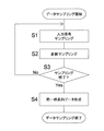
- FIG. 7 is a flowchart showing a data sampling operation in the control system.
- the input signal sampling unit 137 samples the input signal (step S1).
- the input signal is sampled by the high speed sampling method and / or the change time acquisition sampling method. Further, when there are a plurality of input units 13, the period (timing) for sampling the input signal may be different in each input unit 13.
- the sampling period is increased.
- the sampling period is increased. Can be small. As a result, it is possible to avoid acquiring the input signal with a short sampling period for all the input signals. As a result, it is possible to reduce an unnecessary increase in the operating load in the input unit 13.
- the sampling unit 1113 samples the value of the input variable, the value of the output variable, and / or the value of the output variable stored in the variable storage area 1135 (step S2).
- the sampling unit 1113 samples the above variables every predetermined period in which the task is executed.
- the output instruction data created by the user program 1131 is used as sampling data of the sampling value of the output signal.
- the sampling data (output signal data 155a) obtained by the sampling function is used as the sampling data of the sampling value of the output signal. Also good.
- the sampling unit 1113 stores the input signal data 135a (output signal data 155a) transmitted when the I / O refresh process is executed in the sampling data storage area 1137 as the actual sampling data 1137b. As a result, sampling data of the input signal (output signal) is acquired.
- step S3 it is confirmed whether or not the control device 11 has finished sampling. For example, whether sampling has been completed can be determined based on whether a predetermined sampling time has elapsed since sampling was started.
- step S3 If the control device 11 determines that sampling has not ended (in the case of “No” in step S3), the process returns to step S1 to continue data sampling.
- step S3 the process proceeds to step S4 (same time series data creation).
- variable sampling data 1137a After generating variable sampling data 1137a and actual sampling data 1137b, the same time series data is created (step S4). Specifically, first, variable sampling data 1137 a, actual sampling data 1137 b, and output instruction data stored in the sampling data storage area 1137 are transmitted to the development support apparatus 3 via the transmission / reception unit 1119.
- the same time series data creation unit 313 creates the same time series data. Specifically, first, the same time-series data creation unit 313 performs input signal sampling time (first sampling time), second sampling time, and output instruction time in the actual sampling data 1137b (or output sampling in the actual sampling data 1137b). Time) on the same time series. That is, the input signal sampling time, the second sampling time, and the output instruction time (or output sampling time) are rearranged in time order to obtain time data in the same time series data.
- the same time series data creation unit 313 performs actual sampling data 1137b and variable sampling for each of the input signal sampling time, the second sampling time, and the output instruction time (or output sampling time) rearranged in time order.
- the data 1137a and the corresponding sampling value and instruction output signal value of the output instruction data are stored in association with each other. Thereby, the actual sampling data 1137b, the variable sampling data 1137a, and the output instruction data can be unified into the same time series data.
- the same time series data generated by executing the above steps S1 to S4 can be displayed on the same time series data display unit 315 as necessary.
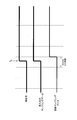
- the value of the variable (input variable) associated with the actual signal changes from 0 to 1 when the execution cycle of the next task after time t 0 is started.
- FIG. 8 is a diagram illustrating a display example when the same time series data is displayed on the same time axis.
- the apparatus can be easily adjusted without imposing a heavy burden on the system developer.
- the input unit 13 acquires the sampling time and the sampling value of the input signal, thereby confirming the temporal change of the actual input signal in the input unit 13. It was.
- the present invention is not limited to this, and the control system 200 according to the second embodiment predicts actual input signals and output signals without acquiring actual input signals and output signals.
- the control system 200 which concerns on 2nd Embodiment is demonstrated.
- the configuration other than the development support device 3 is the same as that of the control system 100 according to the first embodiment. Only the configuration will be described with reference to FIG.
- FIG. 9 is a diagram illustrating a detailed configuration of the development support apparatus of the control system according to the second embodiment.
- a configuration for sampling an input signal and an output signal may or may not have.
- the development support apparatus 3 includes a sampling data reception unit 311 ′, an input / output change time prediction unit 313 ′, a prediction input / output signal generation unit 315 ′, and the same time series. It has a data display unit 317 ′ and an input / output time adjustment unit 319 ′.
- the sampling data receiving unit 311 ′ receives the variable sampling data 1137a stored in the sampling data storage area 1137 from the control device 11 connected to the communication interface 37, and stores it in the storage unit 33 of the development support device 3.
- the input / output change time prediction unit 313 ′ predicts the input change time and / or the output change time based on the connection relationship between the input unit and / or the output unit and the control device, the communication speed, and the second sampling time, respectively.
- the input change time is a time when the signal value of the input signal becomes a value corresponding to the value of the input variable at the second sampling time.
- the output change time is a time at which the signal value of the output signal becomes a value corresponding to the value of the output variable at the second sampling time.
- the input / output change time prediction unit 313 ′ calculates the input change time and the output change time in consideration of the operation time for performing a predetermined operation in the input unit 13 and / or the output unit 15. For example, when the input unit 13 samples the input signal for a predetermined sampling time, the input unit 13 generates the sampling time and the input signal data 135a from the time when the signal requesting transmission of the input signal data 135a is received. It is predicted that sampling of the input signal will start at a time prior to the operation time required for.
- the time (the first time when the transmission request signal must be transmitted from the control device 11). (Corresponding to 2 sampling times) is the time before the transmission request signal reception time by the communication delay time.
- the communication delay between the control device 11 and the input unit 13 and / or the output unit 15 (determined by the connection relationship between the control device 11 and the input unit 13 and / or the output unit 15 and the communication speed). ) And the operation time in the input unit 13 and / or the output unit 15, the input change time and the output change time can be predicted.
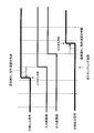
- the predicted input / output signal generation unit 315 ′ generates predicted input / output signal data.
- the predicted input signal data is data generated by associating the value of the input variable at the second sampling time with the input change time. Specifically, for example, as shown in FIG. 10, the predicted input / output signal generation unit 315 ′ shifts the time of the variable sampling data 1137 a forward by the communication delay and the operation time to perform the second sampling. It is obtained by matching the time with the input change time.
- the predicted output signal is data generated by associating the value of the output variable at the second sampling time with the output change time.
- the predicted input / output signal generation unit 315 ′ shifts the time of the variable sampling data 1137a backward in time by the communication delay and the operation time, and sets the second sampling time as the input / output change time. Obtained by matching.
- FIG. 10 is a diagram schematically illustrating generation of a predicted input / output signal.
- the predicted input / output signal generation unit 315 ′ By using the input change time and / or output change time predicted by the input / output change time prediction unit 313 ′, the predicted input / output signal generation unit 315 ′ generates predicted input signal data and / or predicted output signal data, Without sampling the input signal and the output signal, the actual input signal input to the input unit 13 and / or the actual output signal output from the output unit are predicted based on the variables used in the control device 11. it can.
- the same time series data display unit 317 displays the variable sampling data 1137a, the predicted input signal data, and / or the predicted output signal data on the same time axis. Thereby, the relationship between the sampling result of the variable and the predicted input signal and / or output signal can be confirmed on the same time axis without going through a procedure for organizing individual data. As a result, the apparatus can be easily adjusted without imposing a heavy burden on the system developer.
- the input variable a is associated with the input unit 13 connected to the signal input unit 5
- the output variable b is associated with the output unit 15 connected to the motor (control target device 7).
- FIG. 11 is a diagram illustrating an example in which a predicted input signal and a predicted input signal are displayed on the same time axis.
- the sampling data of the input variable a and the output variable b By displaying the sampling data of the input variable a and the output variable b, the sampling data of the input signal, the predicted input signal data and / or the predicted output signal data on the same time axis, for example, output from the output unit 15
- the response time (control delay) of the control target device with respect to the signal, and the change in the value of the variable, the output signal timing, and the response time of the control target device with respect to the input signal with respect to the input signal from the signal input unit 5 are visually I can confirm.
- the input change time and / or the output change time is adjusted, the above data is displayed on the same time axis to facilitate the adjustment.
- the input / output time adjustment unit 319 adjusts the input change time and / or the output change time. Specifically, as illustrated in FIG. 12, the input / output time adjustment unit 319 ′ does not shift the signal change timing in the prediction input signal to the time before the signal change timing of the prediction input signal, or The signal change timing in the output signal is shifted to a time after the signal change timing of the predicted output signal.
- the time when the input signal is input (input change time) and the time when the output signal is output (output change time) can be adjusted in units of the input unit 13 and the output unit 15, respectively.
- FIG. 12 is a diagram schematically illustrating an input / output change time adjustment method.
- the adjustment of the signal change timing in the input / output time adjustment unit 319 ′ described above is performed by using the same time series data display unit 317 ′ for the same time for the predicted input signal data and / or the predicted output signal data and the variable sampling data 1137a. It may be displayed on the axis. Further, when displaying the predicted input signal data and / or the predicted output signal data and the variable sampling data 1137a on the same time series data display unit 317 ′, the adjustable range of the input / output change time is displayed. (FIG. 12). Thereby, it is possible to visually know to what extent the input / output change time can be adjusted.
- the time designation input unit 13 and the time designation output unit 15 are used.
- FIG. 13 is a diagram illustrating a method for reflecting the adjusted output change time in the actual operation of the control system.
- the input / output time adjustment unit 319 ′ can adjust the input change time and / or the output change time, and the input change time and / or the adjustment after the adjustment by the time designation input unit 13 and / or the time designation output unit 15
- the input unit 13 and the output unit 15 unit respectively input signal input time (input change time) and output signal output time ( Output change time) can be adjusted.
- the apparatus can be adjusted more precisely and finely in the control system. That is, the input change time and the output change time can be individually adjusted for each input unit 13 and each output unit 15 based on the speed of the operation of each input unit 13 and each output unit 15.
- the input unit 13 when adjusting the input signal acquisition timing in the input unit 13 and the output signal output timing in the output unit 15, the input unit 13 that takes the longest time until the final processing in the control system 200 is completed. And / or the output unit 15 (which can be visually confirmed by displaying the predicted input signal data, the predicted output signal data, and the variable sampling data 1137a on the same time axis). it can.
- a control system 100 (an example of a control system) according to the first embodiment includes a PLC system 1 (an example of a PLC system) and a development support device 3 (an example of a development support device).
- the PLC system 1 includes an input unit 13 (an example of an input unit), an output unit 15 (an example of an output unit), and a control device 11 (an example of a control device).
- the input unit 13 acquires actual sampling data 1137b (an example of actual sampling data) that stores the first sampling value and the first sampling time in association with each other.
- the first sampling value is a value obtained by sampling the input signal at the first timing.
- the first sampling time is the time when the input signal is sampled.
- the output unit 15 outputs an output signal based on output instruction data including an output instruction time and an instruction output signal value.
- the instruction output signal value is an output signal value to be output at the output instruction time.
- the control device 11 includes a task execution unit 1111 (an example of a task execution unit) and a sampling unit 1113 (an example of a sampling unit).
- the task execution unit 1111 repeatedly executes a task including an I / O refresh process and a user program execution process at a predetermined cycle.
- the I / O refresh process is a process of updating the value of the input variable associated with the input signal based on the input signal and updating the output signal based on the output variable associated with the output signal.
- the user program execution process calculates a value of an output variable by executing a user program 1131 (an example of a user program) based on an input variable, and outputs an output instruction time and an instruction output signal value based on the value of the output variable. Is calculated, and the output instruction data is transmitted to the output unit 15.
- the sampling unit 1113 acquires variable sampling data 1137a (an example of variable sampling data) that stores the second sampling value and the second sampling time in association with each other.
- the second sampling value is a value obtained by sampling the input variable, the output variable, and / or the internal variable at the second timing.
- the internal variable is a variable used in the user program 1131.
- the second sampling time is a time at which the input variable, the output variable, and / or the internal variable is sampled.
- the development support apparatus 3 includes the same time series data creation unit 313 (an example of the same time series data creation unit) and the same time series data display unit 315 (an example of the same time series data display unit).
- the temporary series data creation unit 313 creates the same time series data.
- the first sampling time, the second sampling time, and the output instruction time are arranged on the same time series, and the first sampling value, the second sampling value, and the instruction output signal value are respectively the first time series data.
- This data is stored in association with the time on the same time series corresponding to the sampling time, the second sampling time, and the output instruction time.
- the temporary series data display unit 315 displays the same time series data on the same time axis.
- the input unit 13 samples the input signal at the first timing to obtain a first sampling value, samples the time when the input signal is sampled as the first sampling time, and samples the first sampling value and the first sampling value.
- the actual sampling data is acquired by associating and storing one sampling time.
- the sampling unit 1113 of the control device 11 sets a value obtained by sampling the input variable, the output variable, and / or the internal variable at the second timing as the second sampling value, and the time when the above variable is sampled. Sampling is performed as the second sampling time, and the variable sampling data 1137a is obtained by storing the second sampling time and the second sampling time in association with each other.
- the user program calculates the value of the output variable based on the input variable, and based on the value of the output variable, the output instruction time and The instruction output signal value to be output at the output instruction time is calculated, and output instruction data including the output instruction time and the instruction output signal value is transmitted to the output unit 15.
- the same time series data creation unit 313 arranges the first sampling time, the second sampling time, and the output instruction time on the same time series, and the first sampling value, the second sampling value, and the instruction
- the output signal value is stored in association with the time on the same time series corresponding to the first sampling time, the second sampling time, and the output instruction time, respectively, and the same time series data is created.
- the same time series data display unit 315 displays the same time series data.
- the actual sampling data 1137b, the variable sampling data 1137a, and the output instruction data are collected on the same time series to create one identical time series data.
- the same time series data is displayed on the same time axis. Thereby, the relationship between the sampling result and the instruction output signal value can be confirmed on the same time axis without going through a procedure for organizing individual data. As a result, the apparatus can be easily adjusted without imposing a heavy burden on the system developer.
- the input unit 13 may include a high-speed sampling input unit 13 (an example of a high-speed sampling input unit).
- the high-speed sampling input unit 13 is an input unit that samples the first sampling value every high-speed sampling period shorter than a predetermined period in which the task is executed, and uses the time determined by the high-speed sampling period as the first sampling time. As a result, the input signal can be sampled with higher accuracy in a cycle shorter than a predetermined cycle that is a task execution cycle.
- the input unit 13 may include a change time acquisition input unit 13 (an example of a change time acquisition input unit).
- the change time acquisition input unit 13 uses the timing at which the input signal has changed as a first timing, the signal value of the input signal after the change as a first sampling value, and a time determined by the first timing. Is an input unit having the first sampling time. Thereby, it is possible to accurately sample the time at which the input signal has changed a predetermined time together with the input signal value at the time of the change, without being bound by the task execution cycle (predetermined cycle).
- the input unit 13 may input an input signal at the instructed input instruction time. Thereby, an input signal can be input without being restricted by the task execution period (predetermined period).
- the input unit 13 may input an input signal using a time determined by a high-speed input cycle shorter than a predetermined cycle as an input instruction time. Thus, an input signal can be input at a higher speed than the task execution cycle without being restricted by the task execution cycle (predetermined cycle).
- the output unit 15 may include a high-speed output unit 15 (an example of a high-speed output unit).
- the high-speed output unit 15 outputs an output signal with a time determined by a high-speed output cycle shorter than a predetermined cycle in which a task is executed as an output instruction time, and a signal value to be output every high-speed output cycle as an instruction output signal value It is an output unit that performs.
- the output signal can be controlled and output more finely in a cycle shorter than the predetermined cycle without being bound by the task execution cycle (predetermined cycle).
- the output unit 15 may include a time designation output unit 15 (an example of a time and low output unit).
- the time designation output unit 15 is an output unit that outputs an output signal using a predetermined time as an output instruction time and a signal value to be output at a predetermined time as an instruction output signal value.
- an output signal having an arbitrary signal value can be output at an arbitrary predetermined time without being bound by the task execution period (predetermined period).
- the control system 100 of the first embodiment may further include common time counting units 1117, 133, and 153 (an example of a common time counting unit).
- the common time counting units 1117, 133, and 153 count the first sampling time, the second sampling time, and the output instruction time at the common time.
- deviation of the time counted in the input unit 13, the time counted in the output unit 15, and the time counted in the control apparatus 11 decreases.
- the output unit 15 may store the sampling output signal value obtained by sampling the output signal at a predetermined timing and the output sampling time determined by the predetermined timing in the actual sampling data 1137b. Thereby, an actual output signal can be sampled.
- the temporary series data creation unit 313 further arranges the output sampling time on the same time series, stores the sampling output signal value in association with the time on the same time series corresponding to the output sampling time, and stores the same time series data May be created. Thereby, the sampling result of the actual output signal can be displayed on the same time axis.
- a control system 200 (an example of a control system) according to the second embodiment includes a PLC system 1 (an example of a PLC system) and a development support device 3 (an example of a development support device).
- the PLC system 1 includes an input unit 13 (an example of an input unit), an output unit 15 (an example of an output unit), and a control device 11 (an example of a control device).
- the input unit 13 inputs an input signal.
- the output unit 15 outputs an output signal.
- the control device 11 includes a task execution unit 1111 (an example of a task execution unit) and a sampling unit 1113 (an example of a sampling unit).
- the task execution unit 1111 repeatedly executes a task including an I / O refresh process and a user program execution process at a predetermined cycle.
- the I / O refresh process is a process of updating the value of the input variable associated with the input signal based on the input signal and updating the output signal based on the value of the output variable associated with the output signal.
- the user program execution process is a process of calculating the value of the output variable by executing the user program 1131 (an example of a user program) based on the input variable.
- the sampling unit 1113 acquires variable sampling data 1137a (an example of variable sampling data) that stores the second sampling value and the second sampling time in association with each other.
- the second sampling value is a value obtained by sampling the input variable, the output variable, and / or the internal variable at the second timing.
- the internal variable is a variable used in the user program.
- the second sampling time is a time at which the input variable, the output variable, and / or the internal variable is sampled.
- the development support apparatus 3 includes an input / output change time prediction unit 313 ′ (an example of an input / output change time hot water side), a predicted input / output signal generation unit 315 ′ (an example of a prediction input / output signal generation unit), and the same time series.
- a data display unit 317 ′ (an example of the same time-series data display unit).
- the input / output change time prediction unit 313 ′ determines the input change time and / or the output change time, the connection relationship between the input unit 13 and / or the output unit 15 and the control device 11, the communication speed, the input unit 13 and / or the output unit. 15 is predicted based on the operation speed at which the predetermined operation at 15 is performed and the second sampling time.
- the input change time is a time when the signal value of the input signal becomes a value corresponding to the value of the input variable at the second sampling time.
- the output change time is a time at which the signal value of the output signal becomes a value corresponding to the value of the output variable at the second sampling time.
- the predicted input / output signal generation unit 315 ′ generates predicted input signal data and / or predicted output signal data.
- the predicted input signal data is data generated by associating the value of the input variable at the second sampling time with the input change time.
- the predicted output signal data is data generated by associating the value of the output variable at the second sampling time with the output change time.
- the temporary series data display unit 317 ′ displays variable sampling data, predicted input signal data, and / or predicted output signal data on the same time axis.
- the sampling unit 1113 samples the input variable, the output variable, and / or the internal variable at the second timing to obtain the second sampling, and the input variable, the output variable, and / or The time when the internal variable is sampled is sampled as the second sampling time, and variable sampling data 1137a is acquired.
- the input / output change time prediction unit 313 ′ has an input change time that is a time when the signal value of the input signal becomes a value corresponding to the value of the input variable at the second sampling time, and / or The output change time, which is the time when the signal value of the output signal becomes a value corresponding to the value of the output variable at the second sampling time, the connection relationship between the input unit and / or the output unit and the control device, the communication speed, and the second Predict based on sampling time.
- the predicted input / output signal generation unit 315 ′ creates predicted input signal data by associating the value of the input variable at the second sampling time with the input change time, and sets the value of the output variable at the second sampling time at the output change time. Predicted output signal data is created in association with each other. Further, the same time series data display unit 317 ′ displays the variable sampling data 1137a, the predicted input signal data, and / or the predicted output signal data on the same time axis.
- the input signal input / latch timing input to the input unit 13 and / or the output unit The actual output signal output from 15 can be predicted, and the relationship between the sampling result of the variable and the predicted input signal and / or output signal is on the same time axis without going through the procedure of organizing individual data. Can be confirmed.
- the apparatus can be easily adjusted without imposing a heavy burden on the system developer.
- the development support apparatus 3 may further include an input / output time adjustment unit 319 '(an example of an input / output time adjustment unit).
- the input / output time adjustment unit 319 ' adjusts the input change time and / or the output change time.
- the time when the input signal is input (input change time) and the time when the output signal is output (output change time) can be adjusted in units of the input unit 13 and the output unit 15, respectively.
- the apparatus can be adjusted more precisely and more finely.
- the output unit 15 may output an output signal based on output instruction data including an output instruction time and an instruction output signal value to be output at the output instruction time. Thereby, an output signal can be output without being restricted by the task execution cycle (predetermined cycle).
- the output instruction time may be the output change time, and the instruction output signal may be the value of the output variable at the second sampling time.
- the input instruction time may be an input change time. Thereby, the input change time adjusted in the input / output time adjustment unit 319 'can be reflected in the input unit.
Landscapes
- Physics & Mathematics (AREA)
- General Physics & Mathematics (AREA)
- Engineering & Computer Science (AREA)
- Automation & Control Theory (AREA)
- Programmable Controllers (AREA)
Abstract
Description
例えば、特許文献1には、ユーザプログラムを含むタスクを実行しているときに、ユーザプログラムにおいて参照および更新される変数を収集する制御装置が開示されている。
本発明の一見地に係る制御システムは、PLCシステムと開発支援装置とを備える。
PLCシステムは、入力ユニットと、出力ユニットと、制御装置と、を有する。入力ユニットは、第1サンプリング値と第1サンプリング時刻とを関連づけて記憶する実サンプリングデータを取得する。第1サンプリング値は、入力信号を第1タイミングにおいてサンプリングした値である。第1サンプリング時刻は、入力信号をサンプリングした時刻である。
出力ユニットは、出力指示時刻と指示出力信号値とを含む出力指示データに基づいて、出力信号を出力する。指示出力信号値は、出力指示時刻において出力すべき出力信号値である。
タスク実行部は、I/Oリフレッシュ処理とユーザプログラム実行処理とを含むタスクを、所定の周期にて繰り返し実行する。I/Oリフレッシュ処理は、入力信号に関連づけられた入力変数の値を入力信号に基づいて更新し、出力信号に関連づけられた出力変数に基づいて出力信号を更新する処理のことである。ユーザプログラム実行処理は、入力変数に基づいてユーザプログラムを実行することにより出力変数の値を算出し、出力変数の値に基づいて出力指示時刻と指示出力信号値とを算出し、出力指示データを出力ユニットに送信する処理である。
同一時系列データ作成部は、同一時系列データを作成する。同一時系列データは、第1サンプリング時刻と第2サンプリング時刻と出力指示時刻とが同一時系列上に配置され、第1サンプリング値と第2サンプリング値と指示出力信号値とが、それぞれ、第1サンプリング時刻と第2サンプリング時刻と出力指示時刻に対応する同一時系列上の時刻に関連づけられて記憶されるデータである。
同一時系列データ表示部は、同一時系列データを、同一時間軸上に表示する。
PLCシステムは、入力ユニットと、出力ユニットと、制御装置とを有する。入力ユニットは入力信号を入力する。出力信号は、出力信号を出力する。
タスク実行部は、I/Oリフレッシュ処理とユーザプログラム実行処理とを含むタスクを、所定の周期にて繰り返し実行する。I/Oリフレッシュ処理は、入力信号に関連づけられた入力変数の値を入力信号に基づいて更新し、出力信号に関連づけられた出力変数の値に基づいて出力信号を更新する処理のことである。ユーザプログラム実行処理は、入力変数に基づいてユーザプログラムを実行することにより出力変数の値を算出する処理である。
入出力変化時刻予測部は、入力変化時刻及び/又は出力変化時刻を、入力ユニット及び/又は出力ユニットと制御装置との接続関係、通信速度、入力ユニット及び/又は出力ユニットにおける所定の動作を行う動作速度、及び第2サンプリング時刻に基づいて予測する。入力変化時刻は、入力信号の信号値が第2サンプリング時刻における入力変数の値に対応する値となる時刻である。出力変化時刻は、出力信号の信号値が第2サンプリング時刻における出力変数の値に対応する値となる時刻である。
同一時系列データ表示部は、変数サンプリングデータ、予測入力信号データ、及び/又は予測出力信号データを同一時間軸上に表示する。
さらに、同一時系列データ表示部が、変数サンプリングデータ、予測入力信号データ、及び/又は予測出力信号データを同一時間軸上に表示する。
(1)制御システムの全体構成
まず、第1実施形態に係る制御システム100の全体構成について、図1を用いて説明する。図1は、制御システムの全体構成を示す図である。制御システム100は、PLCシステム1と開発支援装置3とを備える。
PLCシステム1は、例えば、センサやスイッチなどにより構成される信号入力部5から信号を入力する。また、PLCシステム1は、信号入力部5(後述)からの入力信号を必要の応じて用いプログラム(ユーザプログラム1131)を実行して、制御対象機器7を制御する出力信号を算出する。
以下に、PLCシステム1、制御装置11、及び開発支援装置3の詳細な構成についてそれぞれ説明する。
次に、PLCシステム1の詳細な構成について図1を用いて説明する。本実施形態に係るPLCシステム1は、制御装置11と、入力ユニット13と、出力ユニット15と、電源ユニット17と、を有する。
また、ユーザプログラム実行処理中、ユーザプログラム1131は、上記の出力変数を用いて出力指示データ(後述)を作成している。出力指示データは、出力ユニット15(後述)においてどのタイミングにおいて、どのような出力信号値を出力するかを指示するデータである。
また、出力ユニット15は、制御装置11から送信される出力指示データにおいて指示された時刻(出力指示時刻)に指示された信号値(指示出力信号値)の出力信号を出力する。これにより、タスクの実行周期(所定の周期)に束縛されることなく、出力信号を出力できる。
なお、PLCシステム1は、上記の構成要素の全てを1の筐体内に組み込んだシステムであってもよいし、各構成要素を個別の筐体に組み込んで当該構成要素を接続してPLCシステムとしてもよい。特に、入力ユニット13及び出力ユニット15を個別の構成要素とすることにより、PLCシステム1は、所望する制御対象機器及び信号入力部を所望の数接続できる。
次に、制御装置11の構成の詳細について、図3及び図4を用いて説明する。図3は、制御装置及び開発支援装置の構成を示す図である。図4は、制御装置の詳細構成を示す図である。
上記のように、制御装置11はPLCシステムにおけるCPUユニットである。図3に示すように、制御装置11は、プログラムの実行などの演算処理を行うCPU111と、書き込みと読み出しとが可能な記憶領域を提供するRAM113と、読み出しのみを主目的としている記憶領域を提供するROM115と、開発支援装置3、及び/又は、入力ユニット13及び出力ユニット15とデータ通信を行う通信インターフェース117と、を有する。
タスク実行部1111は、RAM113に記憶されたユーザプログラム1131を参照し、ユーザプログラム1131の実行処理と上記のI/Oリフレッシュ処理とを含んだ所定のタスクを所定の周期にて繰り返し実行する。
また、変化時刻取得入力ユニット13(後述)の場合は、入力指示時刻として、変化時刻を取得したい入力信号値の変化を指定する。
I.全体構成
次に、開発支援装置3の構成の詳細について、図3及び図5を用いて説明する。図5は、開発支援装置の詳細構成を示す図である。
開発支援装置3は、例えば、パーソナルコンピュータなどのコンピュータである。よって、図3に示すように、開発支援装置3は、プログラムの実行などの演算処理を行うCPU31と、記憶領域を提供する記憶部33と、キーボードやマウスなどの入力手段により構成されている操作部35と、制御装置11との通信を行う通信インターフェース37と、トレース結果などを表示する表示部39と、を有する。
図5に示すように、開発支援装置3は、サンプリングデータ受信部311と、同一時系列データ作成部313と、同一時系列データ表示部315と、を有する。
次に、PLCシステム1における入力ユニット13及び出力ユニット15の構成について、図6A及び6Bを用いて説明する。図6Aは、入力ユニット及び出力ユニットの構成を示す図である。図6Bは、入力ユニット及びサンプリング機能を有する出力ユニットの構成を示す図である。
まず、入力ユニット13の構成について説明する。入力ユニット13は、入力信号入力部131と、共通時刻計数部133と、入力データ保存部135と、入力信号サンプリング部137と、を有する。
入力信号入力部131は、信号入力部5に接続されており、信号入力部5から入力信号を入力する。入力信号入力部131は、制御装置11のタスク実行部1111においてI/Oリフレッシュ処理が実行された際に、入力した入力信号を、制御装置11へ送信する。これにより、制御装置11においては、I/Oリフレッシュ処理時において、入力した入力信号の値を入力変数へ反映できる。
2つめは、予め決められた時刻を入力指示時刻とする方法である。この方法においては、指定された任意の時刻にて入力信号を入力できる。この方法にて入力信号を入力する入力ユニットを、「時刻指定入力ユニット」と呼ぶことにする。これにより、タスクの実行周期(所定の周期)に束縛されることなく、タスクの実行周期よりも高速に入力信号を入力できる。
1つめは、タスクが実行される所定の周期より短い周期(高速サンプリング周期)毎に入力信号サンプリング値をサンプリングし、高速サンプリング周期により決定される時刻を入力信号サンプリング時刻としてサンプリングする方法(高速サンプリング方法)である。このように、所定の周期よりも短い周期にて入力信号をサンプリングする入力ユニットを、「高速サンプリング入力ユニット」と呼ぶことにする。
2つめは、入力信号取得タイミングを入力信号が所定の変化をしたタイミングとし、所定の変化をした後の入力信号の信号値を入力信号サンプリング値とし、入力信号が所定の変化をしたタイミングである入力信号取得タイミングにより決定される時刻を入力信号サンプリング時刻としてサンプリングする方法(変化時刻取得サンプリング方法)である。このように、入力信号が所定の変化をした際の時刻と所定の変化をした後の入力信号の値をサンプリングする入力ユニットを、「変化時刻取得入力ユニット」と呼ぶことにする。
一方、変化時刻取得入力ユニット13により入力信号をサンプリングすることにより、タスクの実行周期(所定の周期)に束縛されず、入力信号が所定の変化をした時刻を、当該変化をしたときの入力信号値とともに正確にサンプリングできる。
次に、出力ユニット15の構成について説明する。出力ユニット15は、信号出力部151と、共通時刻計数部153と、を有する。
2つめは、予め決められた時刻を出力指示時刻とし、予め決められた時刻に出力すべき信号値を指示出力信号値として出力信号を出力する方法である。この方法により出力信号を出力する出力ユニットを、「時刻指定出力ユニット」と呼ぶことにする。
一方、時刻指定出力ユニット15により出力信号を出力することにより、タスクの実行周期(所定の周期)に束縛されず、予め決められた任意の時刻にて、任意の信号値の出力信号を出力できる。
次に、本実施形態に係る制御システム100におけるデータサンプリング動作について、図7を用いて説明する。図7は、制御システムにおけるデータサンプリング動作を示すフローチャートである。
制御システム100においてデータサンプリングが開始されると、まず、入力ユニット13において、入力信号サンプリング部137が入力信号をサンプリングする(ステップS1)。
これにより、全ての入力信号に対して周期の短いサンプリング周期にて入力信号を取得することを避けられる。その結果、入力ユニット13における動作負荷が無駄に上昇することを低減できる。
なお、図6Bの変形例に示したように、出力ユニット15がサンプリング機能を有する場合には、サンプリング機能にて得られたサンプリングデータ(出力信号データ155a)を出力信号のサンプリング値のサンプリングデータとしてもよい。
例えば、図8に示す例においては、実信号が時刻t0のときに0から1へと変化している場合に、実サンプリングデータにおいては、時刻t0のときに信号値が0から1へと変化している。一方、上記の実信号に関連づけられている変数(入力変数)は、時刻t0の後の次のタスクの実行周期が開始されるときに、値が0から1へと変化している。
図8は、同一時系列データを同一時間軸上に表示したときの表示例を示す図である。
第1実施形態に係る制御システム100においては、入力ユニット13において入力信号のサンプリング時刻とサンプリング値とを取得することにより、入力ユニット13における実際の入力信号の時間的変化を確認していた。
しかし、これに限られず、第2実施形態に係る制御システム200においては、実際の入力信号及び出力信号を取得することなく、実際の入力信号及び出力信号を予測している。以下に、第2実施形態に係る制御システム200について説明する。なお、第2実施形態に係る制御システム200において、開発支援装置3以外の構成については、第1実施形態に係る制御システム100と同じであるため、ここでは説明を省略し、開発支援装置3の構成についてのみ、図9を用いて説明する。図9は、第2実施形態に係る制御システムの開発支援装置の詳細構成を示す図である。
サンプリングデータ受信部311’は、通信インターフェース37に接続された制御装置11から、サンプリングデータ格納領域1137に格納された変数サンプリングデータ1137aを受信し、開発支援装置3の記憶部33に記憶する。
例えば、入力ユニット13において所定のサンプリング時間だけ入力信号をサンプリングする際に、入力信号データ135aの送信を要求する信号を受信した時点から、入力ユニット13においてサンプリング時間と入力信号データ135aを作成するために必要な動作時間より時間的に前の時刻において、入力信号のサンプリングが開始されると予測される。また、入力ユニット13が入力信号データ135aの送信要求信号をある決まった時刻(送信要求信号受信時刻)に受信するためには、制御装置11から送信要求信号を送信しなくてはならない時刻(第2サンプリング時刻に対応)は、送信要求信号受信時刻から通信遅れ時間だけ前の時刻となる。
このようにして、制御装置11と入力ユニット13及び/又は出力ユニット15との間の通信遅れ(制御装置11と入力ユニット13及び/又は出力ユニット15との接続関係と、通信速度により決定される)と、入力ユニット13及び/又は出力ユニット15における動作時間とを考慮して、入力変化時刻及び出力変化時刻を予測できる。
一方、予測出力信号は、出力変化時刻に第2サンプリング時刻における出力変数の値を関連づけて生成されたデータである。具体的には、予測入出力信号生成部315’は、例えば、変数サンプリングデータ1137aの時刻を上記の通信遅れ及び動作時間分時間的に後ろへシフトさせて第2サンプリング時刻を入出力変化時刻に一致させることにより得られる。図10は、予測入出力信号の生成を模式的に示す図である。
入力変数a及び出力変数bのサンプリングデータと、入力信号のサンプリングデータと、予測入力信号データ及び/又は予測出力信号データとを同一時間軸上に表示することにより、例えば、出力ユニット15からの出力信号に対する制御対象機器の応答時間(制御遅れ)、及び、信号入力部5からの入力信号に対する、変数の値の変化、出力信号タイミング、及び、入力信号に対する制御対象機器の応答時間を視覚的に確認できる。
また、後述するように、入力変化時刻及び/又は出力変化時刻を調整する際にも、上記のデータを同一時間軸上に表示することにより、調整をしやすくなる。
この出力指示データ受信した時刻指定出力ユニット15は、タスク開始時刻Tから時間差dだけ後ろの時刻(調整後入出力変化時刻tA)において、出力信号を出力する。図13は、調整後出力変化時刻を、実際の制御システムの動作に反映させるための方法を示す図である。
例えば、入力ユニット13における入力信号取得タイミング、及び、出力ユニット15における出力信号出力タイミングなどを調整する場合に、制御システム200における、最終的な処理が終了するまでに最も時間がかかる入力ユニット13及び/又は出力ユニット15(これは、予測入力信号データ、予測出力信号データ、変数サンプリングデータ1137aを同一時間軸上に表示することにより視覚的に確認できる)に合わせて、上記のタイミングを容易に調整できる。
第1実施形態及び第2実施形態は、下記の構成及び機能を有している。
第1実施形態の制御システム100(制御システムの一例)は、PLCシステム1(PLCシステムの一例)と開発支援装置3(開発支援装置の一例)とを備える。
PLCシステム1は、入力ユニット13(入力ユニットの一例)と、出力ユニット15(出力ユニットの一例)と、制御装置11(制御装置の一例)と、を有する。入力ユニット13は、第1サンプリング値と第1サンプリング時刻とを関連づけて記憶する実サンプリングデータ1137b(実サンプリングデータの一例)を取得する。第1サンプリング値は、入力信号を第1タイミングにおいてサンプリングした値である。第1サンプリング時刻は、入力信号をサンプリングした時刻である。
出力ユニット15は、出力指示時刻と指示出力信号値とを含む出力指示データに基づいて、出力信号を出力する。指示出力信号値は、出力指示時刻において出力すべき出力信号値である。
タスク実行部1111は、I/Oリフレッシュ処理とユーザプログラム実行処理とを含むタスクを、所定の周期にて繰り返し実行する。I/Oリフレッシュ処理は、入力信号に関連づけられた入力変数の値を入力信号に基づいて更新し、出力信号に関連づけられた出力変数に基づいて出力信号を更新する処理のことである。ユーザプログラム実行処理は、入力変数に基づいてユーザプログラム1131(ユーザプログラムの一例)を実行することにより出力変数の値を算出するし、出力変数の値に基づいて出力指示時刻と指示出力信号値とを算出し、出力指示データを出力ユニット15に送信する処理である。
同一時系列データ作成部313は、同一時系列データを作成する。同一時系列データは、第1サンプリング時刻と第2サンプリング時刻と出力指示時刻とが同一時系列上に配置され、第1サンプリング値と第2サンプリング値と指示出力信号値とが、それぞれ、第1サンプリング時刻と第2サンプリング時刻と出力指示時刻に対応する同一時系列上の時刻に関連づけられて記憶されるデータである。
同一時系列データ表示部315は、同一時系列データを、同一時間軸上に表示する。
PLCシステム1は、入力ユニット13(入力ユニットの一例)と、出力ユニット15(出力ユニットの一例)と、制御装置11(制御装置の一例)とを有する。入力ユニット13は入力信号を入力する。出力ユニット15は、出力信号を出力する。
タスク実行部1111は、I/Oリフレッシュ処理とユーザプログラム実行処理とを含むタスクを、所定の周期にて繰り返し実行する。I/Oリフレッシュ処理は、入力信号に関連づけられた入力変数の値を入力信号に基づいて更新し、出力信号に関連づけられた出力変数の値に基づいて出力信号を更新する処理のことである。ユーザプログラム実行処理は、入力変数に基づいてユーザプログラム1131(ユーザプログラムの一例)を実行することにより出力変数の値を算出する処理である。
入出力変化時刻予測部313’は、入力変化時刻及び/又は出力変化時刻を、入力ユニット13及び/又は出力ユニット15と制御装置11との接続関係、通信速度、入力ユニット13及び/又は出力ユニット15における所定の動作を行う動作速度、及び第2サンプリング時刻に基づいて予測する。入力変化時刻は、入力信号の信号値が第2サンプリング時刻における入力変数の値に対応する値となる時刻である。出力変化時刻は、出力信号の信号値が第2サンプリング時刻における出力変数の値に対応する値となる時刻である。
同一時系列データ表示部317’は、変数サンプリングデータ、予測入力信号データ、及び/又は予測出力信号データを同一時間軸上に表示する。
さらに、同一時系列データ表示部317’が、変数サンプリングデータ1137a、予測入力信号データ、及び/又は予測出力信号データを同一時間軸上に表示する。
以上、本発明の一実施形態について説明したが、本発明は上記実施形態に限定されるものではなく、発明の要旨を逸脱しない範囲で種々の変更が可能である。特に、本明細書に書かれた複数の実施形態及び変形例は必要に応じて任意に組み合せ可能である。
1 PLCシステム
11 制御装置
111 CPU
1111 タスク実行部
1113 サンプリング部
1117 共通時刻計数部
1119 送受信部
113 RAM
1131 ユーザプログラム
1135 変数格納領域
1137 サンプリングデータ格納領域
1137a 変数サンプリングデータ
1137b 実サンプリングデータ
115 ROM
115a システムプログラム
117 通信インターフェース
13 入力ユニット
131 入力信号入力部
133 共通時刻計数部
135 入力データ保存部
135a 入力信号データ
137 入力信号サンプリング部
15 出力ユニット
151 信号出力部
153 共通時刻計数部
155 出力データ保存部
155a 出力信号データ
157 出力信号サンプリング部
17 電源ユニット
3 開発支援装置
31 CPU
311 サンプリングデータ受信部
311’ サンプリングデータ受信部
313 同一時系列データ作成部
313’ 入出力変化時刻予測部
315 同一時系列データ表示部
315’ 予測入出力信号生成部
317’ 同一時系列データ表示部
319’ 入出力時刻調整部
33 記憶部
33a 開発支援プログラム
35 操作部
37 通信インターフェース
39 表示部
5 信号入力部
7 制御対象機器
a 入力変数
b 出力変数
B I/Oバス
NW 通信ネットワーク
T タスク開始時刻
d 調整後時間差
tA 調整後入出力変化時刻
Claims (24)
- 入力信号を第1タイミングにおいてサンプリングした第1サンプリング値と、前記入力信号をサンプリングした時刻である第1サンプリング時刻とを関連づけて記憶する実サンプリングデータを取得する入力ユニットと、
出力指示時刻と前記出力指示時刻において出力すべき指示出力信号値とを含む出力指示データに基づいて、出力信号を出力する出力ユニットと、
前記入力信号に関連づけられた入力変数の値を前記入力信号に基づいて更新し、前記出力信号に関連づけられた出力変数に基づいて前記出力信号を更新するI/Oリフレッシュ処理と、前記入力変数に基づいてユーザプログラムを実行することにより前記出力変数の値を算出し、前記出力変数の値に基づいて前記出力指示時刻と前記指示出力信号値とを算出し、前記出力指示データを前記出力ユニットに送信するユーザプログラム実行処理とを含むタスクを、所定の周期にて繰り返し実行するタスク実行部と、
前記入力変数、前記出力変数、及び/又は前記ユーザプログラムにおいて用いられた内部変数を第2タイミングにおいてサンプリングした第2サンプリング値と、前記入力変数、前記出力変数、及び/又は前記内部変数をサンプリングした時刻である第2サンプリング時刻とを関連づけて記憶する変数サンプリングデータとして取得するサンプリング部と、
を有する制御装置と、
を有するPLCシステムと、
前記第1サンプリング時刻と前記第2サンプリング時刻と前記出力指示時刻とが同一時系列上に配置され、前記第1サンプリング値と前記第2サンプリング値と前記指示出力信号値とが、それぞれ、前記第1サンプリング時刻と前記第2サンプリング時刻と前記出力指示時刻に対応する前記同一時系列上の時刻に関連づけられて記憶される同一時系列データを作成する同一時系列データ作成部と、
前記同一時系列データを、同一時間軸上に表示する同一時系列データ表示部と、
を有する開発支援装置と、
を備える制御システム。 - 前記入力ユニットは、前記タスクが実行される前記所定の周期より短い高速サンプリング周期毎に前記第1サンプリング値をサンプリングし、前記高速サンプリング周期により決定される時刻を前記第1サンプリング時刻とする高速サンプリング入力ユニットを含む、請求項1に記載の制御システム。
- 前記入力ユニットは、前記入力信号が所定の変化をしたタイミングを前記第1タイミングとし、前記所定の変化をした後の前記入力信号の信号値を前記第1サンプリング値とし、前記第1タイミングにより決定される時刻を前記第1サンプリング時刻とする変化時刻取得入力ユニットを含む、請求項1又は2に記載の制御システム。
- 前記入力ユニットは、指示された入力指示時刻において前記入力信号を入力する、請求項1~3のいずれかに記載の制御システム。
- 前記入力ユニットは、前記所定の周期よりも短い高速入力周期により決定される時刻を前記入力指示時刻として入力信号を入力する、請求項4に記載の制御システム。
- 前記出力ユニットは、前記タスクが実行される前記所定の周期より短い高速出力周期により決定される時刻を前記出力指示時刻とし、前記高速出力周期毎に出力すべき信号値を前記指示出力信号値として前記出力信号を出力する、高速出力ユニットを含む請求項1~5のいずれかに記載の制御システム。
- 前記出力ユニットは、予め決められた時刻を前記出力指示時刻とし、前記予め決められた時刻に出力すべき信号値を前記指示出力信号値として前記出力信号を出力する、時刻指定出力ユニットを含む請求項1~6のいずれかに記載の制御システム。
- 前記第1サンプリング時刻と、前記第2サンプリング時刻と、前記出力指示時刻とを共通時刻にて計数する共通時刻計数部をさらに備える、請求項1~7のいずれかに記載の制御システム。
- 前記出力ユニットは、さらに、所定のタイミングにおいて前記出力信号をサンプリングしたサンプリング出力信号値と、前記所定のタイミングによって決定される出力サンプリング時刻とを関連づけて前記実サンプリングデータに記憶する、請求項1~8のいずれかに記載の制御システム。
- 前記同一時系列データ作成部は、さらに、前記同一時系列上に前記出力サンプリング時刻を配置し、前記サンプリング出力信号値を前記出力サンプリング時刻に対応する前記同一時系列上の時刻に関連づけて記憶して前記同一時系列データを作成する、請求項9に記載の制御システム。
- 入力信号を入力する入力ユニットと、
出力信号を出力する出力ユニットと、
前記入力信号に関連づけられた入力変数を前記入力信号に基づいて更新し、前記出力信号に関連づけられた出力変数に基づいて前記出力信号を更新するI/Oリフレッシュ処理と、前記入力変数に基づいてユーザプログラムを実行することにより前記出力変数の値を算出するユーザプログラム実行処理とを含むタスクを、所定の周期にて繰り返し実行するタスク実行部と、
前記入力変数、前記出力変数、及び/又は前記ユーザプログラムにおいて用いられた内部変数を第2タイミングにおいてサンプリングした第2サンプリング値と、前記入力変数、前記出力変数、及び/又は前記内部変数をサンプリングした時刻である第2サンプリング時刻とを変数サンプリングデータとして取得するサンプリング部と、を有する制御装置と、
を有するPLCシステムと、
前記入力信号の信号値が前記第2サンプリング時刻における前記入力変数の値に対応する値となる入力変化時刻、及び/又は、前記出力信号の信号値が前記第2サンプリング時刻における前記出力変数の値に対応する値となる出力変化時刻を、前記入力ユニット及び/又は前記出力ユニットと前記制御装置との接続関係、通信速度、前記入力ユニット及び/又は前記出力ユニットにおける所定の動作を行う動作速度、及び前記第2サンプリング時刻に基づいて予測する、入出力変化時刻予測部と、
前記入力変化時刻に前記第2サンプリング時刻における前記入力変数の値を関連づけて予測入力信号データを生成し、及び/又は、前記出力変化時刻に前記第2サンプリング時刻における前記出力変数の値を関連づけて予測出力信号データを生成する、予測入出力信号生成部と、
前記変数サンプリングデータ、前記予測入力信号データ、及び/又は前記予測出力信号データを同一時間軸上に表示する同一時系列データ表示部と、
を有する開発支援装置と、
を備える制御システム。 - 前記開発支援装置は、前記入力変化時刻及び/又は前記出力変化時刻を調整する入出力時刻調整部をさらに有する、請求項11に記載の制御システム。
- 前記出力ユニットは、出力指示時刻と前記出力指示時刻において出力すべき指示出力信号値とを含む出力指示データに基づいて前記出力信号を出力する、請求項11又は12に記載の制御システム。
- 前記出力指示時刻を前記出力変化時刻とし、前記指示出力信号を前記第2サンプリング時刻における前記出力変数の値とする、請求項13に記載の制御システム。
- 前記出力ユニットは、前記タスクが実行される前記所定の周期より短い高速出力周期により決定される時刻を前記出力指示時刻とし、前記高速出力周期毎に出力すべき信号値を前記指示出力信号値として前記出力信号を出力する、高速出力ユニットを含む請求項13又は14に記載の制御システム。
- 前記出力ユニットは、予め決められた時刻を前記出力指示時刻とし、前記予め決められた時刻に出力すべき信号値を前記指示出力信号値として前記出力信号を出力する、時刻指定出力ユニットを含む請求項13~15のいずれかに記載の制御システム。
- 前記出力ユニットは、所定のタイミングにおいて前記出力信号をサンプリングしたサンプリング出力信号値と、前記所定のタイミングによって決定される出力サンプリング時刻とを関連づけて実サンプリングデータに記憶する、請求項11~16のいずれかに記載の制御システム。
- 前記入力ユニットは指示された入力指示時刻において前記入力信号を入力する、請求項11~17のいずれかに記載の制御システム。
- 前記入力指示時刻は前記入力変化時刻である、請求項18に記載の制御システム。
- 前記入力ユニットは、前記所定の周期よりも短い高速入力周期により決定される時刻を前記入力指示時刻として入力信号を入力する、請求項18又は19に記載の制御システム。
- 前記入力変化時刻と、前記出力変化時刻と、前記第2サンプリング時刻とを共通時刻にて計数する共通時刻計数部をさらに備える、請求項11~20のいずれかに記載の制御システム。
- 前記入力ユニットは、前記入力信号を第1タイミングにおいてサンプリングした第1サンプリング値と、前記入力信号をサンプリングした時刻である第1サンプリング時刻とを関連づけて記憶する実サンプリングデータを取得する、請求項11~21のいずれかに記載の制御システム。
- 前記入力ユニットは、前記タスクが実行される前記所定の周期より短い高速サンプリング周期毎に前記第1サンプリング値をサンプリングし、前記高速サンプリング周期により決定される時刻を前記第1サンプリング時刻とする高速サンプリング入力ユニットを含む、請求項22に記載の制御システム。
- 前記入力ユニットは、前記入力信号が所定の変化をしたタイミングを前記第1タイミングとし、前記所定の変化をした後の前記入力信号の信号値を前記第1サンプリング値とし、前記第1タイミングにより決定される時刻を前記第1サンプリング時刻とする時刻取得入力ユニットを含む、請求項22又は23のいずれかに記載の制御システム。
Priority Applications (4)
| Application Number | Priority Date | Filing Date | Title |
|---|---|---|---|
| EP15762038.6A EP3101497B1 (en) | 2014-03-14 | 2015-01-15 | Control system |
| JP2016507379A JP6399082B2 (ja) | 2014-03-14 | 2015-01-15 | 制御システム |
| CN201580011828.XA CN106062647B (zh) | 2014-03-14 | 2015-01-15 | 控制系统 |
| US15/123,294 US10156837B2 (en) | 2014-03-14 | 2015-01-15 | Control systems for setting sampling timing |
Applications Claiming Priority (2)
| Application Number | Priority Date | Filing Date | Title |
|---|---|---|---|
| JP2014052819 | 2014-03-14 | ||
| JP2014-052819 | 2014-03-14 |
Publications (1)
| Publication Number | Publication Date |
|---|---|
| WO2015136971A1 true WO2015136971A1 (ja) | 2015-09-17 |
Family
ID=54071425
Family Applications (1)
| Application Number | Title | Priority Date | Filing Date |
|---|---|---|---|
| PCT/JP2015/050944 Ceased WO2015136971A1 (ja) | 2014-03-14 | 2015-01-15 | 制御システム |
Country Status (5)
| Country | Link |
|---|---|
| US (1) | US10156837B2 (ja) |
| EP (1) | EP3101497B1 (ja) |
| JP (1) | JP6399082B2 (ja) |
| CN (1) | CN106062647B (ja) |
| WO (1) | WO2015136971A1 (ja) |
Cited By (2)
| Publication number | Priority date | Publication date | Assignee | Title |
|---|---|---|---|---|
| JP2017079009A (ja) * | 2015-10-21 | 2017-04-27 | 株式会社キーエンス | プログラマブル・ロジック・コントローラのモニタ装置 |
| JP2020135183A (ja) * | 2019-02-15 | 2020-08-31 | 株式会社安川電機 | 通信システム、通信方法、及びプログラム |
Families Citing this family (6)
| Publication number | Priority date | Publication date | Assignee | Title |
|---|---|---|---|---|
| JP6859922B2 (ja) | 2017-10-24 | 2021-04-14 | オムロン株式会社 | 制御装置、制御装置の制御方法、情報処理プログラム、および記録媒体 |
| JP7074489B2 (ja) * | 2018-02-08 | 2022-05-24 | 株式会社Screenホールディングス | データ処理方法、データ処理装置、および、データ処理プログラム |
| US11169953B2 (en) * | 2018-02-28 | 2021-11-09 | SK Hynix Inc. | Data processing system accessing shared memory by using mailbox |
| WO2019180801A1 (ja) * | 2018-03-20 | 2019-09-26 | 三菱電機株式会社 | 表示装置、表示システム、および表示画面生成方法 |
| KR102763676B1 (ko) * | 2019-04-15 | 2025-02-05 | 엘에스일렉트릭(주) | Plc 시스템 및 이의 입출력 리프레시 주기 제어방법 |
| JP6950772B2 (ja) | 2020-03-13 | 2021-10-13 | 株式会社安川電機 | 生産システム、制御方法、及びプログラム |
Citations (3)
| Publication number | Priority date | Publication date | Assignee | Title |
|---|---|---|---|---|
| JP2000293208A (ja) * | 1999-04-02 | 2000-10-20 | Hitachi Ltd | シーケンス制御システム |
| JP2003248504A (ja) * | 2002-02-22 | 2003-09-05 | Digital Electronics Corp | 制御プログラムのデバッグ方法 |
| WO2014167726A1 (ja) * | 2013-04-12 | 2014-10-16 | 三菱電機株式会社 | プログラマブルコントローラの周辺装置およびデバッグ支援プログラム |
Family Cites Families (9)
| Publication number | Priority date | Publication date | Assignee | Title |
|---|---|---|---|---|
| GB2229536B (en) * | 1989-03-22 | 1993-04-07 | Ferranti Int Signal | Signal processing apparatus and method |
| US6977600B2 (en) * | 2004-02-20 | 2005-12-20 | Fujitsu Limited | Determining analog error using parallel path sampling |
| WO2007144936A1 (ja) | 2006-06-13 | 2007-12-21 | Mitsubishi Electric Corporation | プログラマブルロジックコントローラの周辺装置およびプログラムの自動検証方法 |
| KR101150791B1 (ko) | 2007-09-11 | 2012-06-13 | 도쿄엘렉트론가부시키가이샤 | 정보 처리 장치, 정보 처리 방법 및, 프로그램이 기록된 컴퓨터 판독가능 기록매체 |
| JP4883314B2 (ja) * | 2007-12-12 | 2012-02-22 | オムロン株式会社 | Plcを用いたデータトレースシステム |
| JP5246186B2 (ja) * | 2010-03-15 | 2013-07-24 | オムロン株式会社 | コントローラサポート装置、制御プログラムのシミュレーション方法、コントローラのサポートプログラムおよびコントローラのサポートプログラムを格納したコンピュータ読み取り可能な記憶媒体 |
| JP5252014B2 (ja) | 2011-03-15 | 2013-07-31 | オムロン株式会社 | 制御装置、制御システム、ツール装置および収集指示プログラム |
| JP2013008234A (ja) * | 2011-06-24 | 2013-01-10 | Omron Corp | データ比較装置、データ比較方法、制御プログラムおよび記録媒体 |
| JP6015178B2 (ja) * | 2012-07-11 | 2016-10-26 | オムロン株式会社 | 安全システム |
-
2015
- 2015-01-15 WO PCT/JP2015/050944 patent/WO2015136971A1/ja not_active Ceased
- 2015-01-15 EP EP15762038.6A patent/EP3101497B1/en active Active
- 2015-01-15 CN CN201580011828.XA patent/CN106062647B/zh active Active
- 2015-01-15 US US15/123,294 patent/US10156837B2/en active Active
- 2015-01-15 JP JP2016507379A patent/JP6399082B2/ja active Active
Patent Citations (3)
| Publication number | Priority date | Publication date | Assignee | Title |
|---|---|---|---|---|
| JP2000293208A (ja) * | 1999-04-02 | 2000-10-20 | Hitachi Ltd | シーケンス制御システム |
| JP2003248504A (ja) * | 2002-02-22 | 2003-09-05 | Digital Electronics Corp | 制御プログラムのデバッグ方法 |
| WO2014167726A1 (ja) * | 2013-04-12 | 2014-10-16 | 三菱電機株式会社 | プログラマブルコントローラの周辺装置およびデバッグ支援プログラム |
Cited By (3)
| Publication number | Priority date | Publication date | Assignee | Title |
|---|---|---|---|---|
| JP2017079009A (ja) * | 2015-10-21 | 2017-04-27 | 株式会社キーエンス | プログラマブル・ロジック・コントローラのモニタ装置 |
| JP2020135183A (ja) * | 2019-02-15 | 2020-08-31 | 株式会社安川電機 | 通信システム、通信方法、及びプログラム |
| US11640150B2 (en) | 2019-02-15 | 2023-05-02 | Kabushiki Kaisha Yaskawa Denki | Communication system, communication method, and information storage medium |
Also Published As
| Publication number | Publication date |
|---|---|
| CN106062647A (zh) | 2016-10-26 |
| EP3101497A4 (en) | 2018-04-11 |
| EP3101497B1 (en) | 2020-02-26 |
| JP6399082B2 (ja) | 2018-10-03 |
| US10156837B2 (en) | 2018-12-18 |
| JPWO2015136971A1 (ja) | 2017-04-06 |
| EP3101497A1 (en) | 2016-12-07 |
| CN106062647B (zh) | 2019-04-02 |
| US20170068236A1 (en) | 2017-03-09 |
Similar Documents
| Publication | Publication Date | Title |
|---|---|---|
| JP6399082B2 (ja) | 制御システム | |
| US10761515B2 (en) | Control system for controlling control object and control device for linking control applications in control system | |
| JP5784263B1 (ja) | シミュレーションシステム、プログラマブルコントローラ、シミュレーション装置、エンジニアリングツール | |
| EP3173881A1 (en) | Control parameter tuning device, control parameter tuning method, control parameter tuning program | |
| JP6493506B1 (ja) | 産業用制御システムとその支援装置、制御支援方法およびプログラム | |
| US10180674B2 (en) | Controller and control system | |
| JP6753278B2 (ja) | 制御システムおよび制御装置 | |
| US10768590B2 (en) | Plant operation support device, plant operation support method, and a program device | |
| CN110050237A (zh) | 数据收集装置、数据收集方法及程序 | |
| US10814486B2 (en) | Information processing device, information processing method, and non-transitory computer-readable recording medium | |
| CN108400743B (zh) | 控制装置、控制方法以及计算机存储介质 | |
| JP2019057253A (ja) | 制御装置、制御方法およびサポート装置 | |
| EP3291112A1 (en) | Master and slave architecture for co-simulation of control systems | |
| CN112567299B (zh) | 控制系统、支持装置、存储介质 | |
| CN106462139A (zh) | 可编程显示器以及绘图软件 | |
| US20140236317A1 (en) | Controller, time chart creation device, information storage medium, device control method, and time chart creation method | |
| Carvalho et al. | ISTTOK control system upgrade | |
| EP3361329B1 (en) | Information processing apparatus, system, method and recording medium for generating a user interface | |
| CN107132818A (zh) | 机床的数值控制装置 | |
| JP2023116902A (ja) | 情報処理システム、方法およびプログラム | |
| KR102049291B1 (ko) | 계측 시스템, 제어 장치, 계측 방법 | |
| CN114585979A (zh) | 控制装置 | |
| JP4905782B2 (ja) | プラント制御システム、プラント制御方法およびプラント制御のためのプログラム | |
| JP6248820B2 (ja) | 連携シミュレーション装置 | |
| JP2007536659A (ja) | 自動化システムのシミュレーションのための方法及び装置 |
Legal Events
| Date | Code | Title | Description |
|---|---|---|---|
| 121 | Ep: the epo has been informed by wipo that ep was designated in this application |
Ref document number: 15762038 Country of ref document: EP Kind code of ref document: A1 |
|
| ENP | Entry into the national phase |
Ref document number: 2016507379 Country of ref document: JP Kind code of ref document: A |
|
| REEP | Request for entry into the european phase |
Ref document number: 2015762038 Country of ref document: EP |
|
| WWE | Wipo information: entry into national phase |
Ref document number: 2015762038 Country of ref document: EP |
|
| WWE | Wipo information: entry into national phase |
Ref document number: 15123294 Country of ref document: US |
|
| NENP | Non-entry into the national phase |
Ref country code: DE |