WO2015137148A1 - Dispositif de capture d'image, dispositif d'iris, procédé de capture d'image, et programme - Google Patents
Dispositif de capture d'image, dispositif d'iris, procédé de capture d'image, et programme Download PDFInfo
- Publication number
- WO2015137148A1 WO2015137148A1 PCT/JP2015/055744 JP2015055744W WO2015137148A1 WO 2015137148 A1 WO2015137148 A1 WO 2015137148A1 JP 2015055744 W JP2015055744 W JP 2015055744W WO 2015137148 A1 WO2015137148 A1 WO 2015137148A1
- Authority
- WO
- WIPO (PCT)
- Prior art keywords
- light
- imaging
- optical filter
- aperture
- diaphragm
- Prior art date
- Legal status (The legal status is an assumption and is not a legal conclusion. Google has not performed a legal analysis and makes no representation as to the accuracy of the status listed.)
- Ceased
Links
Images





Classifications
-
- G—PHYSICS
- G03—PHOTOGRAPHY; CINEMATOGRAPHY; ANALOGOUS TECHNIQUES USING WAVES OTHER THAN OPTICAL WAVES; ELECTROGRAPHY; HOLOGRAPHY
- G03B—APPARATUS OR ARRANGEMENTS FOR TAKING PHOTOGRAPHS OR FOR PROJECTING OR VIEWING THEM; APPARATUS OR ARRANGEMENTS EMPLOYING ANALOGOUS TECHNIQUES USING WAVES OTHER THAN OPTICAL WAVES; ACCESSORIES THEREFOR
- G03B9/00—Exposure-making shutters; Diaphragms
- G03B9/02—Diaphragms
- G03B9/06—Two or more co-operating pivoted blades, e.g. iris type
-
- G—PHYSICS
- G02—OPTICS
- G02B—OPTICAL ELEMENTS, SYSTEMS OR APPARATUS
- G02B5/00—Optical elements other than lenses
- G02B5/005—Diaphragms
-
- G—PHYSICS
- G02—OPTICS
- G02B—OPTICAL ELEMENTS, SYSTEMS OR APPARATUS
- G02B5/00—Optical elements other than lenses
- G02B5/20—Filters
- G02B5/22—Absorbing filters
-
- G—PHYSICS
- G03—PHOTOGRAPHY; CINEMATOGRAPHY; ANALOGOUS TECHNIQUES USING WAVES OTHER THAN OPTICAL WAVES; ELECTROGRAPHY; HOLOGRAPHY
- G03B—APPARATUS OR ARRANGEMENTS FOR TAKING PHOTOGRAPHS OR FOR PROJECTING OR VIEWING THEM; APPARATUS OR ARRANGEMENTS EMPLOYING ANALOGOUS TECHNIQUES USING WAVES OTHER THAN OPTICAL WAVES; ACCESSORIES THEREFOR
- G03B11/00—Filters or other obturators specially adapted for photographic purposes
-
- G—PHYSICS
- G03—PHOTOGRAPHY; CINEMATOGRAPHY; ANALOGOUS TECHNIQUES USING WAVES OTHER THAN OPTICAL WAVES; ELECTROGRAPHY; HOLOGRAPHY
- G03B—APPARATUS OR ARRANGEMENTS FOR TAKING PHOTOGRAPHS OR FOR PROJECTING OR VIEWING THEM; APPARATUS OR ARRANGEMENTS EMPLOYING ANALOGOUS TECHNIQUES USING WAVES OTHER THAN OPTICAL WAVES; ACCESSORIES THEREFOR
- G03B33/00—Colour photography, other than mere exposure or projection of a colour film
- G03B33/08—Sequential recording or projection
-
- G—PHYSICS
- G03—PHOTOGRAPHY; CINEMATOGRAPHY; ANALOGOUS TECHNIQUES USING WAVES OTHER THAN OPTICAL WAVES; ELECTROGRAPHY; HOLOGRAPHY
- G03B—APPARATUS OR ARRANGEMENTS FOR TAKING PHOTOGRAPHS OR FOR PROJECTING OR VIEWING THEM; APPARATUS OR ARRANGEMENTS EMPLOYING ANALOGOUS TECHNIQUES USING WAVES OTHER THAN OPTICAL WAVES; ACCESSORIES THEREFOR
- G03B7/00—Control of exposure by setting shutters, diaphragms or filters, separately or conjointly
-
- H—ELECTRICITY
- H04—ELECTRIC COMMUNICATION TECHNIQUE
- H04N—PICTORIAL COMMUNICATION, e.g. TELEVISION
- H04N23/00—Cameras or camera modules comprising electronic image sensors; Control thereof
- H04N23/50—Constructional details
- H04N23/54—Mounting of pick-up tubes, electronic image sensors, deviation or focusing coils
-
- H—ELECTRICITY
- H04—ELECTRIC COMMUNICATION TECHNIQUE
- H04N—PICTORIAL COMMUNICATION, e.g. TELEVISION
- H04N23/00—Cameras or camera modules comprising electronic image sensors; Control thereof
- H04N23/50—Constructional details
- H04N23/55—Optical parts specially adapted for electronic image sensors; Mounting thereof
-
- H—ELECTRICITY
- H04—ELECTRIC COMMUNICATION TECHNIQUE
- H04N—PICTORIAL COMMUNICATION, e.g. TELEVISION
- H04N23/00—Cameras or camera modules comprising electronic image sensors; Control thereof
- H04N23/60—Control of cameras or camera modules
-
- H—ELECTRICITY
- H04—ELECTRIC COMMUNICATION TECHNIQUE
- H04N—PICTORIAL COMMUNICATION, e.g. TELEVISION
- H04N23/00—Cameras or camera modules comprising electronic image sensors; Control thereof
- H04N23/60—Control of cameras or camera modules
- H04N23/667—Camera operation mode switching, e.g. between still and video, sport and normal or high- and low-resolution modes
-
- H—ELECTRICITY
- H04—ELECTRIC COMMUNICATION TECHNIQUE
- H04N—PICTORIAL COMMUNICATION, e.g. TELEVISION
- H04N23/00—Cameras or camera modules comprising electronic image sensors; Control thereof
- H04N23/70—Circuitry for compensating brightness variation in the scene
- H04N23/75—Circuitry for compensating brightness variation in the scene by influencing optical camera components
-
- H—ELECTRICITY
- H04—ELECTRIC COMMUNICATION TECHNIQUE
- H04N—PICTORIAL COMMUNICATION, e.g. TELEVISION
- H04N23/00—Cameras or camera modules comprising electronic image sensors; Control thereof
- H04N23/80—Camera processing pipelines; Components thereof
- H04N23/84—Camera processing pipelines; Components thereof for processing colour signals
-
- H—ELECTRICITY
- H04—ELECTRIC COMMUNICATION TECHNIQUE
- H04N—PICTORIAL COMMUNICATION, e.g. TELEVISION
- H04N2209/00—Details of colour television systems
- H04N2209/04—Picture signal generators
- H04N2209/041—Picture signal generators using solid-state devices
- H04N2209/042—Picture signal generators using solid-state devices having a single pick-up sensor
- H04N2209/043—Picture signal generators using solid-state devices having a single pick-up sensor using an alternating colour separation filter, e.g. colour wheel or colour LCD
-
- H—ELECTRICITY
- H04—ELECTRIC COMMUNICATION TECHNIQUE
- H04N—PICTORIAL COMMUNICATION, e.g. TELEVISION
- H04N2209/00—Details of colour television systems
- H04N2209/04—Picture signal generators
- H04N2209/041—Picture signal generators using solid-state devices
- H04N2209/042—Picture signal generators using solid-state devices having a single pick-up sensor
- H04N2209/045—Picture signal generators using solid-state devices having a single pick-up sensor using mosaic colour filter
-
- H—ELECTRICITY
- H04—ELECTRIC COMMUNICATION TECHNIQUE
- H04N—PICTORIAL COMMUNICATION, e.g. TELEVISION
- H04N23/00—Cameras or camera modules comprising electronic image sensors; Control thereof
- H04N23/10—Cameras or camera modules comprising electronic image sensors; Control thereof for generating image signals from different wavelengths
- H04N23/11—Cameras or camera modules comprising electronic image sensors; Control thereof for generating image signals from different wavelengths for generating image signals from visible and infrared light wavelengths
Definitions
- the present disclosure relates to an imaging device, an iris device, an imaging method, and a program, and more particularly, to an imaging device, an iris device, an imaging method, and a program that can perform multispectral imaging with a smaller mechanism.
- a solid-state imaging device is configured by arranging, for example, color filters of three primary colors of red, green, and blue for each pixel by a Bayer array. And in a solid-state image sensor, the image comprised by three primary colors can be imaged, when a pixel receives the light of each color separated by the color filter.
- a plurality of images composed of the respective colors (hereinafter referred to as multispectral images as appropriate) are captured.
- An imaging device capable of performing the above has been developed.
- light that includes a plurality of image sensors divides light by a beam splitter, and picks up a plurality of multispectral images with light of a color that passes through a color filter fixed to each image sensor.
- An image pickup apparatus employing a division method has been developed.
- a time-division method for imaging a plurality of multispectral images by arranging a plurality of color filters in a mechanically switchable manner in front of one image sensor and sequentially switching the color filters.
- An image pickup apparatus that employs has been developed.
- Patent Document 1 discloses a configuration in which a filter is mounted on an iris blade in an imaging apparatus that simultaneously captures parallax images with a single optical system.
- Patent Document 1 does not disclose a configuration in which those filters are driven in a time-sharing manner.
- An imaging apparatus that employs the light splitting system as described above needs to include imaging elements as many as the number of lights to be split, and there is a concern that the apparatus will be large and costly. Furthermore, the number of multilayer films has increased, and it has been difficult to satisfy the accuracy of specifications.
- an imaging apparatus that employs the time-sharing method as described above needs to have a mechanism for switching color filters by a rotary type, a slide type, or the like, which not only increases the size of the apparatus but also increases power consumption. There is a concern that it may cause failure due to wear.
- the present disclosure has been made in view of such a situation, and enables multispectral imaging to be performed with a smaller mechanism.
- An imaging device includes an imaging element that images a subject, an optical system that forms an image of light from the subject on the imaging element, and an iris mechanism that limits a light amount of light passing through the optical system, And the iris mechanism is provided on at least one of the plurality of diaphragm blades for adjusting the size of the aperture through which the light from the subject passes and the light having a predetermined wavelength. And a plurality of openings at positions where the opening has a predetermined size in a state where the optical filter provided on the diaphragm blade is hidden by the other diaphragm blades other than the diaphragm blade. The diaphragm blades are driven, and the diaphragm blades provided with the predetermined optical filter are sequentially driven so as to cover the opening by the optical filter at a predetermined timing.
- An iris device limits an amount of light that passes through the optical system of an imaging device that includes an imaging device that captures an image of a subject and an optical system that forms an image of light from the subject on the imaging device.
- An iris device that is provided on at least one of the plurality of diaphragm blades for adjusting the size of the aperture through which light from the subject passes and the light of a predetermined wavelength.
- a plurality of optical filters arranged at positions where the opening has a predetermined size in a state where the optical filter provided on the diaphragm blades is hidden by the diaphragm blades other than the diaphragm blades. The diaphragm blades are driven, and the diaphragm blades provided with the predetermined optical filters are sequentially driven at predetermined timings so as to cover the openings by the optical filters.
- An imaging method or program includes an imaging device that images a subject, an optical system that forms an image of light from the subject on the imaging device, and an iris that restricts the amount of light passing through the optical system.
- the iris mechanism is provided on at least one of the plurality of diaphragm blades for adjusting the size of the aperture through which light from the subject passes and the plurality of diaphragm blades, and has a predetermined wavelength.
- the optical filter provided on the diaphragm blade is other than the diaphragm blade.
- a plurality of the diaphragm blades are driven to a position where the opening has a predetermined size while being hidden by the diaphragm blades, and the predetermined optical filter is provided.
- the diaphragm blade includes a step of sequentially driven so as to cover the opening by its optical filter at a predetermined timing.
- a plurality of diaphragm blades are driven to a position where the opening has a predetermined size in a state where the optical filter provided on the diaphragm blades is hidden by other diaphragm blades other than the diaphragm blades. Then, the diaphragm blades provided with the predetermined optical filter are sequentially driven at predetermined timing so as to cover the opening by the optical filter.
- multispectral imaging can be performed with a smaller mechanism.
- FIG. 1 is a block diagram illustrating a configuration example of a first embodiment of an imaging apparatus to which the present technology is applied.
- the imaging apparatus 11 includes a first optical system 21, a second optical system 22, an iris mechanism 23, an imaging element 24, an amplification unit 25, a signal processing unit 26, a control unit 27, and a driving unit 28. Configured. Further, as indicated by a broken line in FIG. 1, the imaging device 11 collects light from the subject to be imaged by the first optical system 21 and the second optical system 22 and images the subject.
- the first optical system 21 and the second optical system 22 constitute an optical system for condensing the light from the subject and forming an image on the light receiving surface of the image pickup device 24. And a plurality of lenses such as a correction lens and an imaging lens.
- the first optical system 21 is disposed closer to the subject than the iris mechanism 23, and the second optical system 22 is disposed closer to the image sensor 24 than the iris mechanism 23.
- the iris mechanism 23 is disposed between the first optical system 21 and the second optical system 22, and controls the amount of light passing through the optical system configured by the first optical system 21 and the second optical system 22.
- the iris mechanism 23 includes a plurality of diaphragm blades (see FIG. 2 to be described later), and changes the size of an opening formed by the diaphragm blades so that light passing through the optical system can be changed. The amount of light can be adjusted.
- the imaging device 24 is configured by, for example, a CCD (Charge-Coupled Device) or a CMOS (Complementary-Metal-Oxide-Semiconductor) image sensor, and captures an image of a subject formed on a light receiving surface on which a plurality of pixels are formed. The obtained image signal is output.
- the image sensor 24 can change the exposure time (shutter speed), which is the time during which the pixel is exposed with light that has passed through the optical system, and performs photoelectric conversion in the pixel, and is controlled by the control unit 27. Imaging is performed with the exposure time.
- the amplifying unit 25 amplifies the image signal output from the image sensor 24 with an amplification factor according to the control by the control unit 27 and supplies the amplified signal to the signal processing unit 26.
- the signal processing unit 26 performs signal processing such as white balance adjustment and gamma correction on the image signal amplified by the amplification unit 25, and outputs the processed signal to a subsequent circuit (not shown).
- the control unit 27 performs control for each block constituting the imaging device 11 and performs imaging processing for imaging the subject. For example, when the user operates an operation unit (not shown) and designates the imaging mode of the imaging device 11, the control unit 27 performs control so that an image is captured in the designated imaging mode.
- the drive unit 28 includes an actuator for driving a plurality of diaphragm blades constituting the iris mechanism 23, a mechanism for transmitting the power of the actuator, and the like. To drive.
- the control unit 27 causes the drive unit 28 to perform an iris mechanism so as to have an appropriate opening according to the brightness of the subject at that time. 23 is driven, and the image sensor 24 is exposed for a predetermined exposure time.
- the imaging device 11 captures an image composed of the three primary colors corresponding to the RGB (red, green, and blue three primary colors) color filters disposed on the light receiving surface of the imaging element 24 (hereinafter referred to as normal. Called imaging).
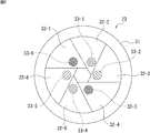
- the imaging device 11 can capture an image that is spectrally separated by more colors than the three primary colors (hereinafter referred to as multispectral imaging as appropriate). That is, as shown in FIG. 2, the plurality of diaphragm blades 32 constituting the iris mechanism 23 are provided with an optical filter 33 that transmits light in a specific wavelength range. Imaging with light having a wavelength transmitted through the filter 33 can be performed.
- the iris mechanism 23 is configured by attaching six diaphragm blades 32-1 to 32-6 to an iris outer shell 31, and each of the six diaphragm blades 32-1 to 32-6 has a structure.
- Six optical filters 33-1 to 33-6 are provided.
- FIG. 2 shows the iris mechanism 23 in the minimum stop state in which the aperture formed by the stop blades 32-1 to 32-6 is stopped so as to be the smallest.
- Aperture blades 32-1 to 32-6 are attached to the iris outline 31 so as to be openable and closable, and openings formed by the aperture blades 32-1 to 32-6 are formed in the first optical system 21 and the second optical system.
- An iris outline 31 is mounted on the imaging device 11 so as to be disposed on the optical axis of the system 22.
- a storage space for storing the diaphragm blades 32-1 to 32-6 in a maximum throttle state in which the opening is maximized is provided inside the iris outer shell 31, and the diaphragm blade 32-1 is provided.
- a mechanism for opening and closing 32 to 6 is incorporated.
- the aperture blades 32-1 to 32-6 are driven in conjunction with each other from the maximum aperture state to the minimum aperture state, thereby changing the size of the aperture through which the light irradiated to the image sensor 24 passes. Further, the diaphragm blades 32-1 to 32-6 are configured such that each of the diaphragm blades 32-1 to 32-6 can be driven independently in sequence when the aperture is in the minimum diaphragm state. For example, as will be described later with reference to FIG. 4, the diaphragm blades 32-1 to 32-6 are driven so that the optical filters 33-1 to 33-6 are sequentially disposed in the aperture in the minimum diaphragm state. .
- the optical filters 33-1 to 33-6 transmit light in a wavelength range narrower than the wavelength range transmitting the color filters of the RGB color filters arranged on the light receiving surface of the image sensor 24. Further, the optical filters 33-1 to 33-6 are arranged at positions hidden by the diaphragm blades 32-1 to 32-6 from the maximum aperture state to the minimum aperture state. During normal imaging, the optical filter 33-1 is disposed. Thru 33-6 are prevented from transmitting light. For example, the optical filter 33 provided on a predetermined diaphragm blade 32 is arranged at a position hidden by another diaphragm blade 32 adjacent to the diaphragm blade 32.
- FIG. 3 shows a state in which the diaphragm blades 32-1 to 32-6 are sequentially arranged one by one at the arrangement position in the minimum diaphragm state.
- FIG. 3A shows a state where the diaphragm blades 32-1 are arranged at the arrangement positions in the minimum diaphragm state
- FIG. 3B shows the diaphragm blades 32-1 and 32-2.
- a state of being arranged at an arrangement position in the minimum aperture state is shown.
- the optical filter 33-1 (A in FIG. 3) of the diaphragm blade 32-1 is hidden by the diaphragm blade 32-2 adjacent to the diaphragm blade 32-1.
- FIG. 3C shows a state in which the diaphragm blades 32-1 to 32-3 are arranged at the arrangement positions in the minimum diaphragm state, and the optical filter 33-2 ( 3B is hidden by the diaphragm blade 32-3 adjacent to the diaphragm blade 32-2.
- FIG. 3D shows a state in which the diaphragm blades 32-1 to 32-4 are arranged at the arrangement positions in the minimum diaphragm state, and the optical filter 33-3 of the diaphragm blade 32-3 is shown. (C in FIG. 3) is hidden by the diaphragm blade 32-4 adjacent to the diaphragm blade 32-3.
- FIG. 3E shows a state in which the diaphragm blades 32-1 to 32-5 are arranged at the arrangement positions in the minimum diaphragm state, and the optical filter 33-4 ( 3) is hidden by the diaphragm blade 32-5 adjacent to the diaphragm blade 32-4.
- FIG. 3F shows a state in which the diaphragm blades 32-1 to 32-6 are arranged at the arrangement positions in the minimum diaphragm state, and the optical filter 33-5 of the diaphragm blade 32-5 is shown. (E in FIG. 3) is hidden by the diaphragm blade 32-6 adjacent to the diaphragm blade 32-5. Further, the optical filter 33-6 of the diaphragm blade 32-6 is hidden by the diaphragm blade 32-1 adjacent to the diaphragm blade 32-6.
- the optical filters 33-1 to 33-6 are hidden from the maximum aperture state to the minimum aperture state.
- imaging is performed with light passing through the opening while the optical filters 33-1 to 33-6 are hidden.
- the optical filters 33-1 to 33-6 are sequentially disposed in the aperture of the minimum aperture state, and light transmitted through the optical filters 33-1 to 33-6, respectively. The imaging is performed by.
- FIG. 4A shows a state in which the optical filter 33-1 is disposed at the aperture in the minimum aperture state when the aperture blade 32-1 is driven from the minimum aperture state.
- FIG. 4B shows a state where the optical filter 33-2 is disposed in the aperture in the minimum aperture state by driving the aperture blade 32-2 from the minimum aperture state.
- FIG. 4C shows a state in which the optical filter 33-3 is disposed in the aperture in the minimum aperture state, and
- FIG. 4D shows the optical filter 33-4 in the minimum aperture state.
- positioned in opening of is shown.
- FIG. 4E shows a state in which the optical filter 33-5 is disposed in the minimum aperture state opening, and
- FIG. 4F illustrates the optical filter 33-6 in the minimum aperture state opening. The state of arrangement is shown.
- the optical filters 33-1 to 33-6 are sequentially disposed in the aperture in the minimum aperture state, and each of the optical filters 33-1 to 33-6 is transmitted. An image of light in the wavelength range to be captured can be taken in a time division manner.
- FIG. 5 shows the spectral sensitivity, which is the difference in sensitivity according to the wavelength of light, with the horizontal axis representing the wavelength and the vertical axis representing the spectral sensitivity.
- FIG. 5 shows peak distributions of red, green, and blue light sensitivities.
- the optical filters 33-1 to 33-6 transmit light in the wavelength ranges W1 to W6 obtained by dividing the predetermined range into six parts in the visible light range (for example, 380 nm to 780 nm).
- the optical filter 33-1 transmits light in the wavelength range W1 of about 400 nm to 445 nm
- the optical filter 33-2 transmits light in the wavelength range W2 of about 445 nm to 490 nm
- the optical filter 33-3 Transmits light in the wavelength range W3 of about 490 nm to 535 nm.
- the optical filter 33-4 transmits light in the wavelength range W4 of about 535 nm to 580 nm, the optical filter 33-5 transmits light in the wavelength range W5 of about 580 nm to 625 nm, and the optical filter 33-6 Transmits light in the wavelength range W6 of approximately 625 nm to 670 nm.
- the imaging device 11 spectrally separates light having a wavelength from the wavelength range W1 to the wavelength range W6 using the optical filters 33-1 to 33-6, and thereby, by time-sharing, images by light in the respective wavelength ranges.
- An image can be taken. That is, the imaging device 11 can capture an image with a higher wavelength resolution than, for example, a normal RGB color filter.
- FIG. 6A shows the iris mechanism 23 in the maximum aperture state that is opened so that the opening is maximized.
- the imaging device 11 performs imaging with the iris mechanism 23 set to the maximum aperture state.
- FIG. 6B shows the iris mechanism 23 in the minimum throttle state in which the aperture is throttled to be the smallest.
- the imaging device 11 performs imaging with the iris mechanism 23 in the minimum aperture state.
- FIG. 6C shows the iris mechanism 23 in a state where the predetermined optical filter 33 is disposed in the aperture in the minimum aperture state.
- the imaging device 11 performs imaging by arranging the optical filter 33 in the aperture in the minimum aperture state.
- FIG. 7 shows a flowchart for explaining the imaging process by the imaging apparatus 11.
- the control unit 27 selects the imaging mode in either the multispectral imaging mode for performing multispectral imaging or the normal imaging mode for performing normal imaging. Determine whether it is set.
- the user can set the imaging mode by operating an operation unit (not shown).
- step S11 when the control unit 27 determines that the imaging mode is set to the multispectral imaging mode, the process proceeds to step S12, and the control unit 27 minimizes the iris mechanism 23 with respect to the drive unit 28. Control is performed so that the aperture state is reached.
- the drive unit 28 drives the diaphragm blades 32-1 to 32-6 of the iris mechanism 23 to bring the iris mechanism 23 into the minimum diaphragm state as shown in FIG. 6B.
- step S13 the control unit 27 sets the amplification factor of the amplification unit 25 or the exposure time of the image sensor 24 to a value suitable for the multispectral imaging mode.
- the control unit 27 sets the amplification factor of the amplification unit 25 to be equivalent to the image brightness in normal imaging so that the brightness of an image captured in multispectral imaging is appropriate.
- the amplifying unit 25 amplifies the image signal so that the signal intensity of the image signal maintains the signal intensity of the image signal output during normal imaging.
- the exposure time of the image sensor 24 may be increased so that long exposure is performed.
- step S14 the control unit 27 determines whether or not the shutter operation has been performed by the user, and waits for processing until it is determined that the user has performed the shutter operation.
- the control unit 27 determines that the shutter operation has been performed, and the process proceeds to step S15.
- step S15 the control unit 27 sets 1 to a capture signal N that is a parameter for designating an Nth image among a plurality of images captured in multispectral imaging.
- a capture signal N that is a parameter for designating an Nth image among a plurality of images captured in multispectral imaging. For example, as shown in FIG. 2, when the iris mechanism 23 is provided with six optical filters 33-1 to 33-6, the capture signal N is sequentially set to values 1 to 6. Is done.
- step S16 the control unit 27 controls the driving unit 28 so as to close the Nth diaphragm blade 32-N among the diaphragm blades 32-1 to 32-6.
- the drive unit 28 drives the Nth aperture blade 32-N to close, and the optical filter 33-N is disposed in the aperture in the minimum aperture state as shown in FIG. 6C.
- step S17 the control unit 27 controls the imaging device 24 to perform imaging, and the imaging device 24 transmits light in a wavelength range that transmits the optical filter 33-N disposed in the opening of the iris mechanism 23. Perform imaging with.
- the amplification unit 25 amplifies the image signal output from the imaging element 24 according to the amplification factor set in step S13, and is imaged with light in the Nth wavelength range via the signal processing unit 26. An image is output.
- step S18 the control unit 27 controls the drive unit 28 to open the Nth diaphragm blade 32-N among the diaphragm blades 32-1 to 32-6, and the drive unit 28 controls the Nth aperture blade 32-N. Drive the blades 32-N to open.
- step S19 the control unit 27 determines whether or not imaging has been performed with light in the wavelength ranges of all of the optical filters 33-1 to 33-6, that is, all of the diaphragm blades 32-1 to 32-6 are sequentially applied. It is determined whether or not imaging is performed in the closed state.
- step S20 the control unit 27 determines whether the imaging mode is set to the multispectral imaging mode or the normal imaging mode. In step S20, when the control unit 27 determines that the imaging mode is set to the multispectral imaging mode, the process returns to step S14, and the same process is repeated thereafter.
- step S20 determines in step S20 that the imaging mode is set to the normal imaging mode
- the process proceeds to step S21, and the control unit 27 moves the iris mechanism 23 to the drive unit 28.
- Control to initialize.
- the drive unit 28 releases the minimum aperture state of the iris mechanism 23 set in step S12, and the iris mechanism 23 is controlled so as to have an opening corresponding to the brightness of the subject in normal imaging.
- step S22 the control unit 27 initializes the amplification factor of the amplification unit 25.
- the amplification unit 25 is controlled so as to cancel the amplification factor set in step S13 and achieve an amplification factor according to the brightness of the subject in normal imaging.
- step S22 After the process of step S22 or when the control unit 27 determines in step S11 that the imaging mode is set to the normal imaging mode, the process proceeds to step S23, and the control unit 27 performs normal imaging.
- Each block of the imaging device 11 is controlled. That is, the aperture size of the iris mechanism 23 is appropriately controlled according to the brightness of the subject, the exposure time of the image sensor 24 is controlled, and the amplification factor of the amplifying unit 25 is controlled to perform imaging. And a process is complete
- the imaging device 11 can perform imaging by switching between the multispectral imaging mode and the normal imaging mode.
- the optical filters 33-1 to 33-6 are sequentially arranged in the aperture of the minimum aperture state at a predetermined timing, and a plurality of sheets of light transmitted through the optical filters 33-1 to 33-6 are respectively used.
- Multiple spectral images can be taken in a time-sharing manner.
- the wavelength characteristics of the three primary color filters arranged for each pixel on the light receiving surface of the image sensor 24 and the wavelength characteristics of the optical filters 33-1 to 33-6 are overlapped to obtain the wavelength characteristics of light.
- a multispectral image is captured.
- the light from the subject has a large incident angle (high NA (Numerical Aperture)) with respect to the normal of the optical filter 33 , And the optical filter 33 is allowed to pass through the optical filter 33 with a small incident angle (low NA) with respect to the normal line of the optical filter 33, thereby reducing the influence of the incident angle dependence of the optical filter 33. it can. Thereby, the wavelength accuracy can be improved.
- high NA Numerical Aperture
- the imaging device 11 can output an image signal having the same signal strength as that during normal imaging by amplifying the image signal by the amplification unit 25.
- the imaging device 11 in addition to increasing the amplification factor of the amplification unit 25, for example, by increasing the exposure time of the imaging device 24 and increasing the image signal as frame integration, the signal intensity equivalent to that during normal imaging is obtained.
- the image signal can be output.
- the imaging device 11 realizes multispectral imaging only by providing the optical filters 33-1 to 33-6 on the diaphragm blades 32-1 to 32-6 of the iris mechanism 23, for example, as compared with the conventional imaging device. And there is no need to increase the number of new mounting components. Therefore, for example, the imaging device 11 has a more compact mechanism than the imaging device that realizes multispectral imaging by imaging light split by a beam splitter using a plurality of imaging elements. Can be realized.
- the imaging apparatus 11 is configured to include six optical filters 33-1 to 33-6, but the number of optical filters 33 is not limited to six, and is at least three (usually normal). More than RGB, and may be 6 or more or 6 or less. Further, it is not necessary that all the diaphragm blades 32-1 to 32-6 are provided with the optical filter 33, and the number of the diaphragm blades 32 and the number of the optical filters 33 may be different. For example, a configuration in which the optical filter 33 is provided on only four or five of the six diaphragm blades 32-1 to 32-6, or a plurality of optical filters 33 are provided on one diaphragm blade 32. A configuration or the like can be adopted.
- the optical filter 33 is set so as to transmit light in the wavelength range of visible light as shown in FIG. 5 described above and also transmit light in a wavelength range other than visible light (for example, infrared light). be able to.
- the image sensor 24 can be configured such that the color filters of the three primary colors as described above are not arranged for each pixel. That is, in this case, the image sensor 24 is configured to detect only the luminance signal, and captures an image with light having only the wavelength characteristics of the optical filters 33-1 to 33-6 disposed in the opening of the iris mechanism 23. Can do.
- FIG. 8 is a block diagram illustrating a configuration example of the second embodiment of the imaging apparatus to which the present technology is applied.
- the imaging apparatus 11A includes a first optical system 21, a second optical system 22, an imaging element 24, an amplification unit 25, a signal processing unit 26, a control unit 27, and a driving unit 28, as shown in FIG.
- the configuration is the same as that of the imaging device 11.
- the imaging device 11A has a different configuration from the imaging device 11 of FIG. 1 in that the imaging device 11A includes an iris mechanism 23A.
- the iris mechanism 23A is disposed between the first optical system 21 and the second optical system 22, and restricts the amount of light passing through the optical system, similar to the iris mechanism 23 of FIG.
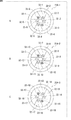
- the iris mechanism 23 in FIG. 1 is configured by six diaphragm blades 32-1 to 32-6, whereas the iris mechanism 23A is configured by stacking three iris mechanisms 23 to obtain eighteen diaphragm blades 32. -1 to 32-18.
- the iris mechanism 23A includes a first iris mechanism portion 23A-1, a second iris mechanism portion 23A-2, and a third iris mechanism portion 23A-3 as shown in FIG. Configured.
- the first iris mechanism portion 23A-1, the second iris mechanism portion 23A-2, and the third iris mechanism portion 23A-3 are each configured similarly to the iris mechanism 23 (FIG. 2).
- the first iris mechanism portion 23A-1 shown in FIG. 9A is configured by six optical filters 33-1 to 33-6 provided on six diaphragm blades 32-1 to 32-6, respectively. Is done.
- the second iris mechanism portion 23A-2 shown in FIG. 9B includes six diaphragm blades 32-7 to 32-12 and six optical filters 33-7 to 33-12, respectively. Is done.
- the third iris mechanism portion 23A-3 shown in FIG. 9C includes six diaphragm blades 32-13 to 32-18 and six optical filters 33-13 to 33-18, respectively. Is done.
- the aperture blades 32-1 to 32-18 are individually driven sequentially in order, and the optical filters 33-1 to 33-18 are driven. -18 is placed in the aperture in the minimum aperture state.
- the optical filters 33-1 to 33-18 transmit light in different wavelength ranges.
- imaging is performed with light transmitted through the optical filters 33-1 to 33-18. Thereby, the multispectral image by the light for each narrower wavelength range can be taken.
- the configuration in which the diaphragm blade 32 provided in the iris mechanism 23 is provided with the optical filter 33 has been described.
- a multi-spectral structure is obtained by combining a normal iris mechanism and an optical filter changer. Imaging may be performed.
- the normal iris mechanism 23B is configured without the optical filters 33-1 to 33-6.
- the optical filter changer 61 is configured such that the turret 62 provided with the optical filters 33-1 to 33-6 can rotate around the rotating portion 63.
- the optical filters 33-1 to 33-6 are sequentially arranged in the opening of the normal iris mechanism 23B by rotating the turret 62, and transmitted through the optical filters 33-1 to 33-6, respectively. Imaging with light can be performed.
- the turret 62 is formed with a large opening 64, and the large opening 64 is disposed on the optical axis during normal imaging.
- the normal iris mechanism 23B is configured without the optical filters 33-1 to 33-6.
- the optical filter changer 71 is configured such that the plate 72 provided with the optical filters 33-1 to 33-6 is slidable. At the time of multispectral imaging, the optical filters 33-1 to 33-6 are sequentially arranged by sliding the plate 72 through the opening of the normal iris mechanism 23B, and transmitted through the optical filters 33-1 to 33-6, respectively. Imaging with light can be performed.
- a large opening 73 is formed in the plate 72, and the large opening 73 is disposed on the optical axis during normal imaging.
- the processes described with reference to the flowcharts described above do not necessarily have to be processed in chronological order in the order described in the flowcharts, but are performed in parallel or individually (for example, parallel processes or objects). Processing).
- the program may be processed by one CPU, or may be distributedly processed by a plurality of CPUs.
- the above-described series of processing can be executed by hardware or can be executed by software.
- a program constituting the software executes various functions by installing a computer incorporated in dedicated hardware or various programs.
- the program is installed in a general-purpose personal computer from a program recording medium on which the program is recorded.
- control unit 27 in FIG. 1 includes a storage unit including a CPU (Central Processing Unit), a ROM (Read Only Memory), a RAM (Random Access Memory), a nonvolatile memory, and the like.
- a program stored in the ROM or the storage unit is loaded into the RAM and executed by the CPU, whereby the above-described series of processing is performed.
- the program can be downloaded via a communication unit or a removable medium, and can be installed or updated in the storage unit.
- this technique can also take the following structures.
- An image sensor for imaging a subject An optical system for imaging light from the subject onto the image sensor; An iris mechanism for limiting the amount of light passing through the optical system, The iris mechanism is A plurality of aperture blades for adjusting the size of the aperture through which light from the subject passes; An optical filter provided on at least one of the plurality of diaphragm blades and transmitting light of a predetermined wavelength; In a state where the optical filter provided on the diaphragm blade is hidden by the other diaphragm blades other than the diaphragm blade, a plurality of the diaphragm blades are driven to a position where the opening has a predetermined size, The imaging device in which the diaphragm blades provided with the predetermined optical filter are sequentially driven so as to cover the opening by the optical filter at a predetermined timing.
- the optical filters are sequentially arranged in the aperture, and the plurality of optical filters are
- the imaging apparatus according to (1) wherein multispectral imaging is performed in which a plurality of images are transmitted in a time-division manner using light that has passed through each.
- the image pickup device further includes an amplification unit that amplifies an image signal output by imaging the subject.
- the amplifying unit maintains the signal intensity of the image signal output at the time of imaging other than the multispectral imaging so that the signal intensity of the image signal output at the time of the multispectral imaging is maintained.
- the imaging device according to (2) wherein the signal is amplified.
- the imaging element is configured to maintain the signal intensity of the image signal output when imaging other than the multispectral imaging is performed, so that the signal intensity of the image signal output during the multispectral imaging is maintained.
- the imaging device according to (2) wherein an exposure time by light from the light is increased.
- a normal imaging mode in which an image is captured by light that does not pass through the optical filter of the iris mechanism; and a multispectral imaging mode in which a plurality of images are captured by light that respectively passes through the plurality of optical filters of the iris mechanism.
- the imaging device according to any one of (1) to (4).
- the iris mechanism is provided on at least one of the plurality of diaphragm blades that adjust the size of the aperture through which light from the subject passes and the light of a predetermined wavelength is transmitted.
- the imaging apparatus according to any one of (1) to (5), wherein a plurality of iris mechanism units each including an optical filter are configured to be stacked in the optical axis direction of the optical system.
- the imaging element is configured by arranging a color filter of three primary colors in a predetermined arrangement for each pixel arranged on a light receiving surface that receives light from the subject, and a plurality of the optical elements arranged in the opening.
- the imaging device according to any one of (1) to (6), wherein an image is captured by light having wavelength characteristics obtained by being superimposed on the wavelength characteristics of the filter.
- the imaging device according to any one of (1) to (6), wherein the imaging element captures an image using only light having a wavelength characteristic of the plurality of optical filters arranged in the opening.
- the iris mechanism is provided with at least three or more optical filters, and performs imaging with light dispersed into at least three or more wavelength ranges.
- Imaging device. (10) The optical filter transmits light in a wavelength range narrower than the wavelength range of light transmitted by each of the three primary color filters arranged on the light receiving surface of the image sensor. (1) to (9) The imaging device described in 1.
- the imaging device according to any one of (1) to (10), wherein the optical filter transmits light in a specific wavelength range in a wavelength range of visible light or a wavelength range other than visible light.
- An iris device that limits an amount of light that passes through the optical system of an imaging device that includes an imaging device that images a subject and an optical system that forms an image of light from the subject on the imaging device, A plurality of aperture blades for adjusting the size of the aperture through which light from the subject passes; An optical filter provided on at least one of the plurality of diaphragm blades and transmitting light of a predetermined wavelength; In a state where the optical filter provided on the diaphragm blade is hidden by the other diaphragm blades other than the diaphragm blade, a plurality of the diaphragm blades are driven to a position where the opening has a predetermined size, An iris device in which the diaphragm blades provided with the predetermined optical filter are sequentially driven so as to cover the opening by the optical filter at
- An imaging device that images a subject; an optical system that forms an image of light from the subject on the imaging device; and an iris mechanism that limits an amount of light that passes through the optical system, the iris mechanism including the subject
- An imaging apparatus comprising: a plurality of aperture blades that adjust the size of an aperture through which light from the light passes; and an optical filter that is provided on at least one of the plurality of aperture blades and transmits light of a predetermined wavelength
- the imaging method of comprising: driving the diaphragm blades provided with the predetermined optical filter so as to cover the opening with the optical filter sequentially at a predetermined timing.
- An imaging device that images a subject; an optical system that forms an image of light from the subject on the imaging device; and an iris mechanism that limits an amount of light that passes through the optical system, the iris mechanism including the subject
- An imaging apparatus comprising: a plurality of aperture blades that adjust the size of an aperture through which light from the light passes; and an optical filter that is provided on at least one of the plurality of aperture blades and transmits light of a predetermined wavelength
- a program to be executed by a computer for controlling In a state where the optical filter provided on the diaphragm blade is hidden by the other diaphragm blades other than the diaphragm blade, the plurality of diaphragm blades are driven to a position where the opening has a predetermined size
- a program that causes a computer to execute processing including a step of driving the diaphragm blades provided with a predetermined optical filter so as to cover the opening with the optical filter sequentially at a predetermined timing.
- imaging device 21 first optical system, 22 second optical system, 23 iris mechanism, 24 imaging element, 25 amplification unit, 26 signal processing unit, 27 control unit, 28 drive unit, 31 iris outline, 32-1 Thru 32-6 diaphragm blade, 33-1 thru 33-6 optical filter, 61 optical filter changer, 62 turret, 63 rotating part, 64 large opening, 71 optical filter changer, 72 plate, 73 large opening
Landscapes
- Physics & Mathematics (AREA)
- General Physics & Mathematics (AREA)
- Engineering & Computer Science (AREA)
- Multimedia (AREA)
- Signal Processing (AREA)
- Optics & Photonics (AREA)
- Blocking Light For Cameras (AREA)
- Studio Devices (AREA)
- Diaphragms For Cameras (AREA)
- Exposure Control For Cameras (AREA)
- Color Television Image Signal Generators (AREA)
Abstract
Priority Applications (3)
| Application Number | Priority Date | Filing Date | Title |
|---|---|---|---|
| JP2016507444A JP6478126B2 (ja) | 2014-03-14 | 2015-02-27 | 撮像装置、アイリス装置、撮像方法、およびプログラム |
| CN201580011922.5A CN106063259B (zh) | 2014-03-14 | 2015-02-27 | 成像设备、可变光圈装置、成像方法和程序 |
| US15/123,717 US10018890B2 (en) | 2014-03-14 | 2015-02-27 | Imaging apparatus, iris device and imaging method |
Applications Claiming Priority (2)
| Application Number | Priority Date | Filing Date | Title |
|---|---|---|---|
| JP2014-051897 | 2014-03-14 | ||
| JP2014051897 | 2014-03-14 |
Publications (1)
| Publication Number | Publication Date |
|---|---|
| WO2015137148A1 true WO2015137148A1 (fr) | 2015-09-17 |
Family
ID=54071596
Family Applications (1)
| Application Number | Title | Priority Date | Filing Date |
|---|---|---|---|
| PCT/JP2015/055744 Ceased WO2015137148A1 (fr) | 2014-03-14 | 2015-02-27 | Dispositif de capture d'image, dispositif d'iris, procédé de capture d'image, et programme |
Country Status (4)
| Country | Link |
|---|---|
| US (1) | US10018890B2 (fr) |
| JP (1) | JP6478126B2 (fr) |
| CN (1) | CN106063259B (fr) |
| WO (1) | WO2015137148A1 (fr) |
Cited By (1)
| Publication number | Priority date | Publication date | Assignee | Title |
|---|---|---|---|---|
| WO2022137896A1 (fr) * | 2020-12-23 | 2022-06-30 | ソニーセミコンダクタソリューションズ株式会社 | Dispositif d'imagerie |
Families Citing this family (9)
| Publication number | Priority date | Publication date | Assignee | Title |
|---|---|---|---|---|
| US10077885B2 (en) * | 2015-06-15 | 2018-09-18 | Martin Professional Aps | Iris diaphragm system |
| EP3285116B1 (fr) * | 2016-08-17 | 2020-07-08 | Leica Instruments (Singapore) Pte. Ltd. | Dispositif d'iris multispectral |
| EP3440989A1 (fr) * | 2017-08-09 | 2019-02-13 | Koninklijke Philips N.V. | Système d'imagerie d'un il |
| WO2020163492A1 (fr) * | 2019-02-06 | 2020-08-13 | California Institute Of Technology | Spectromètre hyperspectral compact dans l'infrarouge moyen |
| JP7309640B2 (ja) * | 2020-03-18 | 2023-07-18 | 株式会社東芝 | 光学検査装置 |
| DE102020127996A1 (de) * | 2020-10-23 | 2022-04-28 | Bayerische Motoren Werke Aktiengesellschaft | Vorrichtung zum Auswerten von Bilddaten in einem Kraftfahrzeug |
| US20250060576A1 (en) * | 2021-12-21 | 2025-02-20 | Leica Instruments (Singapore) Pte. Ltd. | Microscope System and Corresponding Method |
| CN116400550A (zh) * | 2023-03-20 | 2023-07-07 | 南京理工大学 | 一种基于可变光圈编码的成像系统及超分辨方法 |
| EP4506752A1 (fr) * | 2023-08-09 | 2025-02-12 | Yuk Sum Chan | Mécanisme d'arrêt d'ouverture et module de lentille |
Citations (3)
| Publication number | Priority date | Publication date | Assignee | Title |
|---|---|---|---|---|
| JPS6439180A (en) * | 1987-08-04 | 1989-02-09 | Brother Ind Ltd | Color image pickup device |
| JPH1042303A (ja) * | 1996-07-25 | 1998-02-13 | Mitsubishi Electric Corp | 撮像装置 |
| JP2003134533A (ja) * | 2001-10-30 | 2003-05-09 | Pentax Corp | ステレオ画像撮像装置 |
Family Cites Families (15)
| Publication number | Priority date | Publication date | Assignee | Title |
|---|---|---|---|---|
| GB9515328D0 (en) * | 1995-07-26 | 1995-09-20 | Willson Peter D W | Apparatus for modifying light quality:-diaphagm,colour changer and dimmer |
| JP3697047B2 (ja) * | 1998-02-02 | 2005-09-21 | キヤノン株式会社 | 撮像装置 |
| US7567286B2 (en) * | 1998-02-02 | 2009-07-28 | Canon Kabushiki Kaisha | Image pickup apparatus |
| JP2002049073A (ja) * | 2000-08-07 | 2002-02-15 | Asahi Precision Co Ltd | Cctvカメラ用レンズの絞り装置 |
| US20070047803A1 (en) * | 2005-08-30 | 2007-03-01 | Nokia Corporation | Image processing device with automatic white balance |
| JP4818721B2 (ja) * | 2005-12-28 | 2011-11-16 | キヤノン電子株式会社 | 光学部材 |
| JP2010164803A (ja) * | 2009-01-16 | 2010-07-29 | Olympus Corp | 光調節装置 |
| WO2011007435A1 (fr) * | 2009-07-16 | 2011-01-20 | 株式会社山野光学 | Butée douverture |
| US8398263B2 (en) * | 2010-01-20 | 2013-03-19 | Ikonisys, Inc. | Filter wheel |
| EP2666402B1 (fr) * | 2011-01-20 | 2020-04-15 | VS Technology Corporation | Un dispositif de source lumineuse ayant un diaphragme d'ouverture d'éclairage |
| WO2013125768A1 (fr) * | 2012-02-21 | 2013-08-29 | 중앙대학교 산학협력단 | Appareil et procédé pour détecter automatiquement un objet et des informations de profondeur d'image photographiée par un dispositif de capture d'image ayant une ouverture de filtre à couleurs multiples |
| CN103344333A (zh) * | 2013-06-18 | 2013-10-09 | 中国计量学院 | 一种快速准连续多光谱成像系统及其成像方法 |
| CA3028775C (fr) * | 2014-03-04 | 2020-01-07 | Novadaq Technologies ULC | Ouvertures de filtrage spatial et spectral et systemes d'imagerie optique comportant lesdites ouvertures |
| WO2015174295A1 (fr) * | 2014-05-14 | 2015-11-19 | ソニー株式会社 | Dispositif et procédé de capture d'images |
| US20160341372A1 (en) * | 2015-05-22 | 2016-11-24 | Stcube, Inc. | Led lamp capable of freely converting color temperature and method for converting color temperature using the same |
-
2015
- 2015-02-27 WO PCT/JP2015/055744 patent/WO2015137148A1/fr not_active Ceased
- 2015-02-27 US US15/123,717 patent/US10018890B2/en active Active
- 2015-02-27 JP JP2016507444A patent/JP6478126B2/ja not_active Expired - Fee Related
- 2015-02-27 CN CN201580011922.5A patent/CN106063259B/zh not_active Expired - Fee Related
Patent Citations (3)
| Publication number | Priority date | Publication date | Assignee | Title |
|---|---|---|---|---|
| JPS6439180A (en) * | 1987-08-04 | 1989-02-09 | Brother Ind Ltd | Color image pickup device |
| JPH1042303A (ja) * | 1996-07-25 | 1998-02-13 | Mitsubishi Electric Corp | 撮像装置 |
| JP2003134533A (ja) * | 2001-10-30 | 2003-05-09 | Pentax Corp | ステレオ画像撮像装置 |
Cited By (1)
| Publication number | Priority date | Publication date | Assignee | Title |
|---|---|---|---|---|
| WO2022137896A1 (fr) * | 2020-12-23 | 2022-06-30 | ソニーセミコンダクタソリューションズ株式会社 | Dispositif d'imagerie |
Also Published As
| Publication number | Publication date |
|---|---|
| JP6478126B2 (ja) | 2019-03-06 |
| US20170017135A1 (en) | 2017-01-19 |
| CN106063259A (zh) | 2016-10-26 |
| US10018890B2 (en) | 2018-07-10 |
| JPWO2015137148A1 (ja) | 2017-04-06 |
| CN106063259B (zh) | 2018-11-02 |
Similar Documents
| Publication | Publication Date | Title |
|---|---|---|
| JP6478126B2 (ja) | 撮像装置、アイリス装置、撮像方法、およびプログラム | |
| US9681057B2 (en) | Exposure timing manipulation in a multi-lens camera | |
| US20200084363A1 (en) | Temporally aligned exposure bracketing for high dynamic range imaging | |
| US9787915B2 (en) | Method and apparatus for multi-spectral imaging | |
| US8259203B2 (en) | Method and apparatus for achieving panchromatic response from a color-mosaic imager | |
| WO2005088984A1 (fr) | Dispositif d'analyse d'images multi-spectre et lentille d'adaptation | |
| WO2017104411A1 (fr) | Élément d'imagerie, dispositif et procédé de traitement d'image, et programme associé | |
| JP2006211416A (ja) | 画像処理装置及び方法 | |
| US20130038767A1 (en) | Imaging apparatus and method of driving solid-state imaging device | |
| US20130076947A1 (en) | Single-shot high dynamic range imaging | |
| CN108496360B (zh) | 图像处理装置、图像处理方法和记录了程序的介质 | |
| JP5199736B2 (ja) | 画像撮像装置 | |
| US10178327B2 (en) | Imaging device, method for controlling imaging device, and control program | |
| JP2010258669A (ja) | 全方位撮像装置 | |
| JP5681589B2 (ja) | 撮像装置及び画像処理方法 | |
| WO2016052101A1 (fr) | Dispositif de capture d'images et programme de génération de données d'images | |
| US10178360B2 (en) | Imaging sensor coupled with layered filters | |
| GB2548460A (en) | Imaging apparatus and control method thereof | |
| JP4415318B2 (ja) | カラー画像の色ずれ補正方法及びカラー画像撮像装置 | |
| JP4239219B2 (ja) | オートホワイトバランス調整方法及び装置 | |
| JP2003287674A (ja) | カメラ | |
| JP4043379B2 (ja) | 撮像装置 | |
| RU2736780C1 (ru) | Устройство для формирования цветного изображения (варианты) | |
| JP2016066985A (ja) | 二板式カラーまたは白黒撮像装置と二板式カラーまたは白黒撮像装置の画像処理方法 | |
| JP2011188387A (ja) | 撮像装置および電子情報機器 |
Legal Events
| Date | Code | Title | Description |
|---|---|---|---|
| 121 | Ep: the epo has been informed by wipo that ep was designated in this application |
Ref document number: 15762217 Country of ref document: EP Kind code of ref document: A1 |
|
| ENP | Entry into the national phase |
Ref document number: 2016507444 Country of ref document: JP Kind code of ref document: A |
|
| WWE | Wipo information: entry into national phase |
Ref document number: 15123717 Country of ref document: US |
|
| NENP | Non-entry into the national phase |
Ref country code: DE |
|
| 122 | Ep: pct application non-entry in european phase |
Ref document number: 15762217 Country of ref document: EP Kind code of ref document: A1 |