WO2015137184A1 - Disposiitf de tête d'aspiration et de manipulation de feuilles - Google Patents
Disposiitf de tête d'aspiration et de manipulation de feuilles Download PDFInfo
- Publication number
- WO2015137184A1 WO2015137184A1 PCT/JP2015/056135 JP2015056135W WO2015137184A1 WO 2015137184 A1 WO2015137184 A1 WO 2015137184A1 JP 2015056135 W JP2015056135 W JP 2015056135W WO 2015137184 A1 WO2015137184 A1 WO 2015137184A1
- Authority
- WO
- WIPO (PCT)
- Prior art keywords
- suction
- groove
- sheet
- grooves
- suction surface
- Prior art date
- Legal status (The legal status is an assumption and is not a legal conclusion. Google has not performed a legal analysis and makes no representation as to the accuracy of the status listed.)
- Ceased
Links
Images






Classifications
-
- H—ELECTRICITY
- H01—ELECTRIC ELEMENTS
- H01G—CAPACITORS; CAPACITORS, RECTIFIERS, DETECTORS, SWITCHING DEVICES, LIGHT-SENSITIVE OR TEMPERATURE-SENSITIVE DEVICES OF THE ELECTROLYTIC TYPE
- H01G13/00—Apparatus specially adapted for manufacturing capacitors; Processes specially adapted for manufacturing capacitors not provided for in groups H01G4/00 - H01G11/00
-
- B—PERFORMING OPERATIONS; TRANSPORTING
- B28—WORKING CEMENT, CLAY, OR STONE
- B28B—SHAPING CLAY OR OTHER CERAMIC COMPOSITIONS; SHAPING SLAG; SHAPING MIXTURES CONTAINING CEMENTITIOUS MATERIAL, e.g. PLASTER
- B28B11/00—Apparatus or processes for treating or working the shaped or preshaped articles
- B28B11/14—Apparatus or processes for treating or working the shaped or preshaped articles for dividing shaped articles by cutting
-
- B—PERFORMING OPERATIONS; TRANSPORTING
- B65—CONVEYING; PACKING; STORING; HANDLING THIN OR FILAMENTARY MATERIAL
- B65H—HANDLING THIN OR FILAMENTARY MATERIAL, e.g. SHEETS, WEBS, CABLES
- B65H3/00—Separating articles from piles
- B65H3/08—Separating articles from piles using pneumatic force
- B65H3/0808—Suction grippers
- B65H3/0816—Suction grippers separating from the top of pile
-
- H—ELECTRICITY
- H01—ELECTRIC ELEMENTS
- H01G—CAPACITORS; CAPACITORS, RECTIFIERS, DETECTORS, SWITCHING DEVICES, LIGHT-SENSITIVE OR TEMPERATURE-SENSITIVE DEVICES OF THE ELECTROLYTIC TYPE
- H01G4/00—Fixed capacitors; Processes of their manufacture
- H01G4/30—Stacked capacitors
Definitions
- the present invention relates to a suction head, and more particularly to a suction head having a suction surface for holding a ceramic green sheet.
- the present invention also relates to a sheet handling apparatus, and in particular, a ceramic having a base having a mounting surface on which a carrier sheet (carrier film) holding a ceramic green sheet is mounted, and a suction surface facing the mounting surface.
- the present invention relates to a sheet handling apparatus including a suction head that sucks a green sheet.
- a ceramic green sheet formed in a carrier sheet shape is prepared, and the ceramic green sheet having a predetermined dimension is cut out and then peeled off from the carrier sheet. And the ceramic green sheet peeled from the carrier sheet is laminated
- An example of a suction head and a sheet handling apparatus that can be used in this step is disclosed in Patent Document 1.
- the suction head is connected to a specific one of the suction holes, and an opening larger than the diameter of the suction holes is positioned on the suction surface.
- the suction grooves are provided so as to be intermittently distributed in the portion corresponding to the peripheral portion of the ceramic green sheet. By forming such suction grooves, it is said that the ceramic green sheet can be reliably and easily peeled off from the carrier film.
- a main object of the present invention is to provide a suction head and a sheet handling device capable of reliably and easily peeling a ceramic green sheet from a carrier film while suppressing sheet damage due to suction.
- a suction head according to the present invention (14: reference numeral corresponding to the embodiment; the same applies hereinafter) is a suction head (14) having a suction surface for holding a ceramic green sheet (20), and the suction surface includes a plurality of suction surfaces.
- Suction holes (HL, HL, ...) and a plurality of grooves (GR, GR, 7), the plurality of grooves on at least one side of the end region in the suction surface and on the outer periphery of the suction surface
- a suction hole provided in a direction along the suction hole and disposed in an end region in the suction surface among the plurality of suction holes is provided so as to pass through the groove.
- the groove width of the groove is smaller than the diameter of the suction hole arranged in the end region in the suction surface.
- the groove provided on the outermost periphery of the suction surface is provided further outside than the outermost suction hole arranged on the outermost side among the plurality of suction holes, and It is provided in contact with the outer periphery of the outermost suction hole.
- the distance between the groove provided on the outermost periphery of the suction surface and the end of the suction surface among the plurality of grooves is adjusted by adjusting the groove width of the groove provided on the outermost periphery. Yes.
- a connecting groove for connecting the plurality of grooves is further provided.
- each of the plurality of grooves has a chamfered end portion in the width direction.
- each edge of the plurality of suction holes is chamfered.
- the sheet handling apparatus (10) is: The substrate (12) having a placement surface on which the carrier sheet (18) holding the ceramic green sheet (20) is placed, and the suction surface facing the placement surface, sucking the ceramic green sheet
- a sheet handling device comprising a suction head (14),
- the suction surface has a plurality of suction holes (HL, HL, ...) and a plurality of grooves (GR, GR, 7),
- the plurality of grooves are provided on at least one side of the end region in the suction surface in a direction along the outer periphery of the suction surface; Of the plurality of suction holes, a suction hole disposed in an end region within the suction surface is provided so as to pass through the groove.
- a suction head and a sheet handling apparatus capable of reliably and easily peeling a ceramic green sheet from a carrier film while suppressing sheet damage due to suction.
- FIG. 1 is a perspective view showing a part of the sheet handling apparatus of the present invention.
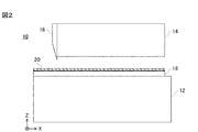
- FIG. 2 is a view of the sheet handling apparatus shown in FIG. 1 when viewed in the Y-axis direction, and shows an example of a state in which a carrier sheet having a ceramic green sheet formed on the upper surface is disposed under the suction head.
- FIG. 3 is an illustrative view showing an example of a state in which a ceramic green sheet on a carrier sheet is cut with a cutting blade.
- FIG. 4 is an illustrative view showing an example of a state in which the cut sheet piece is sucked by the suction head and peeled off from the carrier sheet.
- FIG. 1 is a perspective view showing a part of the sheet handling apparatus of the present invention.
- FIG. 2 is a view of the sheet handling apparatus shown in FIG. 1 when viewed in the Y-axis direction, and shows an example of a state in which a carrier sheet having a ceramic green sheet formed on the upper surface is
- FIG. 5A is an enlarged perspective view showing a part of an example of the shape of the suction head
- FIG. 5B is an enlarged view showing a part of a groove and a suction hole provided on the suction surface of the suction head
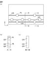
- FIG. 6A is an enlarged plan view showing a part of the suction surface of the suction head.
- 6 (b) is a cross-sectional view taken along the line AA in FIG. 6 (a)
- FIG. 6 (c) is a cross-sectional view taken along the line BB in FIG. 6 (a).
- 7 (a) and 7 (b) are cross-sectional views taken along arrows BB in FIG. 6 (a) of the modified groove shape.
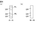
- FIG. 8 is a cross-sectional view of a modification of the groove shape.
- 8A is an arrow cross-sectional view at a position corresponding to AA in FIG. 6A
- FIG. 8B is a cross-sectional view at a position corresponding to BB in FIG. 6A.
- FIG. FIG. 9A and FIG. 9B are enlarged plan views showing a part of the suction surface of the suction head of another example.
- FIG. 10A is an enlarged view showing a part of a groove and a suction hole provided on the suction surface of another example of the suction head.
- FIG. 10B is an enlarged plan view showing a part of the suction surface of the suction head.
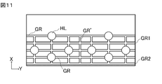
- FIG. 11 is an enlarged plan view showing a part of the suction surface of the suction head of still another example.
- the sheet handling apparatus 10 of this embodiment includes a rectangular parallelepiped base 12.
- the X axis, the Y axis, and the Z axis are assigned to the length direction, the width direction, and the height direction of the rectangular parallelepiped forming the base 12.
- the carrier sheet 18 has a width corresponding to the width of the base 12 and an arbitrary length, and is intermittently conveyed from the negative side to the positive side in the X-axis direction by a conveyance roller (not shown).
- a ceramic green sheet 20 is entirely formed on the upper surface of the carrier sheet 18.
- the ceramic green sheet 20 is referred to as “green sheet 20”.
- a rectangular parallelepiped suction head 14 is disposed above the base 12.
- the length direction, the width direction, and the height direction of the rectangular parallelepiped forming the suction head 14 are along the X axis, the Y axis, and the Z axis, respectively.
- the suction head 14 has four side surfaces, and a cutting blade 16 is provided on each side surface.
- the blade length of the cutting blade 16 coincides with the length or width dimension of the suction head 14.
- FIG. 1 only the cutting blade 16 provided on the negative side surface in the X-axis direction of the suction head 14 is illustrated for easy explanation.
- the carrier sheet 18 is intermittently conveyed from the negative side to the positive side in the X-axis direction.
- a downward suction force is generated on the mounting surface of the base 12, and then the suction head 14 is lowered.
- the green sheet 20 formed on the upper surface of the carrier sheet 18 is cut by a cutting blade when the suction head 14 is lowered (see FIGS. 2 to 3).
- the size of the main surface of the sheet piece 22 obtained by cutting matches the size of the suction surface of the suction head 14.
- the sheet piece 22 is held on the suction surface by the suction force generated in the suction head 14.
- the downward suction force generated on the mounting surface of the base 12 is released after the sheet piece 22 is held on the suction surface.
- the suction head 14 is then raised to the original position before the descent.
- the sheet piece 22 held on the suction surface is peeled off from the carrier sheet 18 and rises as the suction head 14 rises (see FIG. 4).
- the suction force generated in the suction head 14 is released when the sheet piece 22 is moved to another process.
- a plurality of suction holes HL and a plurality of grooves GR are formed on the suction surface of the suction head 14.
- the plurality of suction holes HL are connected to a vacuum source (not shown).
- the plurality of grooves GR are provided in the end region in the suction surface in a direction along the outer periphery of the suction surface. In the figure, the groove GR is provided along the outer periphery of each side in the suction surface and is connected at the four corners, but it may be provided at least on one side.
- suction holes arranged in the end region within the suction surface are provided so as to pass through the groove GR.
- the groove GR is preferably provided in the Y-axis direction.
- the sheet piece 22 is gradually peeled from the vicinity of the outer periphery toward the center with respect to the carrier film 18.
- the groove GR is continuously formed on at least one side of the end region of the suction surface, one end of the sheet piece 22 can be fixed over the entire side, and the sheet piece 22 is fixed to the carrier sheet. It becomes possible to peel from 18 stably.
- the opening shape of the suction hole HL is circular, and the groove width of the groove GR is preferably smaller than the diameter of the suction hole HL arranged in the end region in the suction surface.
- the diameter of the suction hole arranged in the end region is preferably in the range of 0.1 mm to 1 mm.
- the groove width is preferably in the range of 0.05 mm to 0.5 mm. If the groove GR occupies the same area on the suction surface, for example, it is more difficult to provide a large number of narrow grooves than a few wide grooves, so that the green sheet is less likely to penetrate into the groove during suction. It is preferable because the deformation of the green sheet can be suppressed.
- FIG. 6A is an enlarged plan view showing a part of the suction surface of the suction head shown in FIG. 6 (b) is a cross-sectional view taken along the line AA in FIG. 6 (a), and FIG. 6 (c) is a cross-sectional view taken along the line BB in FIG. 6 (a).
- the depth of the groove GR is preferably in the range of 0.01 mm to 0.5 mm.
- the cross-sectional shape of the groove GR in the width direction is a rectangular shape, but as shown in FIG. 7A, the cross-sectional shape may be an arc shape (R shape). It may be V-shaped as shown in 7 (b). It is preferable that the corner portion of the groove has an R shape because the green sheet 20 can be hardly damaged even if the green sheet 20 is deformed so as to be in close contact with the inner surface of the groove GR in the local peeling step.
- both ends in the width direction of the groove GR are chamfered.
- the corners forming the ends are dropped and a curved surface finish is applied.
- each edge of the plurality of suction holes HL is chamfered.
- FIG. 8A a cross-sectional view taken along the line AA in FIG. 6A is shown in FIG. 8A, for example, at the position corresponding to BB.
- FIG. 8B the cross-sectional view taken along the arrow shows that the width direction end of the groove GR and the edge of the suction hole HL are curved.
- the groove GRO provided on the outermost periphery can be provided further outside the outermost suction hole HLO disposed on the outermost side of the suction surface so as to be in contact with the outer periphery of the outermost suction hole HLO.
- the position of the groove GRO provided on the outermost periphery of the suction surface is preferably closer to the end of the suction surface.
- the distance between the groove GRO provided on the outermost periphery and the end of the suction surface can be adjusted by adjusting the groove width of the groove GRO provided on the outermost periphery.
- the sheet piece 22 can be held at the end portion even though the suction hole arrangement is the same as that in FIG.
- FIG. 10 is a view showing another example of the suction head of the present invention.
- FIG. 10A is an enlarged view showing a part of a groove and a suction hole provided on the suction surface of the suction head of this example.
- FIG. 10B is an enlarged plan view showing a part of the suction surface of the suction head.
- a connecting groove GR ′ that connects the plurality of grooves GL is further provided.
- the connecting groove GR ′ is provided in a direction orthogonal to the groove GR, but the shape and direction are not limited to this as long as the grooves GL are connected to each other.
- connecting groove GR ′ for connecting the grooves GL in this way, it is possible to provide the groove GR1 that can suck and hold the green sheet 20 (sheet piece 22) without passing through the suction hole. Therefore, by providing the connecting groove GR ', it is possible to adjust the interval and number of grooves regardless of the number and position of the suction holes.
- FIG. 11 is an enlarged plan view showing a part of the suction surface of the suction head of still another example of the suction head of the present invention.
- the connection groove GR ′ by providing the connection groove GR ′, the green sheet 20 (sheet piece 22) is sucked and held also in the region at the extreme end of the suction surface where it is difficult to form a suction hole. It is possible to provide a groove GR2 that can be used.
- the ceramic green sheet is suppressed while suppressing sheet damage due to suction. Can be reliably and easily peeled off from the carrier film.
- the suction pressure is ⁇ 60 kPa
- a green sheet having a thickness of about 1 to 3 ⁇ m can be peeled well, and even a thinner green sheet can be handled by adjusting the suction pressure and the like. is there.
- the suction area increases when suction is performed in the groove GR, a desired suction force can be ensured even if the number of suction holes HL is small. Thereby, the cost for processing the suction head 14 can be suppressed.
Landscapes
- Engineering & Computer Science (AREA)
- Power Engineering (AREA)
- Manufacturing & Machinery (AREA)
- Microelectronics & Electronic Packaging (AREA)
- Mechanical Engineering (AREA)
- Structural Engineering (AREA)
- Chemical & Material Sciences (AREA)
- Ceramic Engineering (AREA)
- Devices For Post-Treatments, Processing, Supply, Discharge, And Other Processes (AREA)
- Fixed Capacitors And Capacitor Manufacturing Machines (AREA)
- Ceramic Capacitors (AREA)
- Producing Shaped Articles From Materials (AREA)
Abstract
Priority Applications (3)
| Application Number | Priority Date | Filing Date | Title |
|---|---|---|---|
| KR1020167023306A KR101851546B1 (ko) | 2014-03-13 | 2015-03-03 | 흡인 헤드 및 시트 취급 장치 |
| JP2016507461A JP6213664B2 (ja) | 2014-03-13 | 2015-03-03 | 吸引ヘッドおよびシート取扱装置 |
| CN201580013467.2A CN106103025B (zh) | 2014-03-13 | 2015-03-03 | 抽吸头及片材处理装置 |
Applications Claiming Priority (2)
| Application Number | Priority Date | Filing Date | Title |
|---|---|---|---|
| JP2014050208 | 2014-03-13 | ||
| JP2014-050208 | 2014-03-13 |
Publications (1)
| Publication Number | Publication Date |
|---|---|
| WO2015137184A1 true WO2015137184A1 (fr) | 2015-09-17 |
Family
ID=54071632
Family Applications (1)
| Application Number | Title | Priority Date | Filing Date |
|---|---|---|---|
| PCT/JP2015/056135 Ceased WO2015137184A1 (fr) | 2014-03-13 | 2015-03-03 | Disposiitf de tête d'aspiration et de manipulation de feuilles |
Country Status (4)
| Country | Link |
|---|---|
| JP (1) | JP6213664B2 (fr) |
| KR (1) | KR101851546B1 (fr) |
| CN (1) | CN106103025B (fr) |
| WO (1) | WO2015137184A1 (fr) |
Cited By (1)
| Publication number | Priority date | Publication date | Assignee | Title |
|---|---|---|---|---|
| US20220161323A1 (en) * | 2020-11-26 | 2022-05-26 | S.A.S 3Dceram-Sinto | Machine for manufacturing green parts from ceramic or metallic material |
Citations (2)
| Publication number | Priority date | Publication date | Assignee | Title |
|---|---|---|---|---|
| JPS61200212U (fr) * | 1985-06-03 | 1986-12-15 | ||
| JP2000269075A (ja) * | 1999-03-19 | 2000-09-29 | Murata Mfg Co Ltd | セラミックグリーンシートの取扱装置および取扱方法ならびに積層セラミック電子部品の製造方法 |
Family Cites Families (3)
| Publication number | Priority date | Publication date | Assignee | Title |
|---|---|---|---|---|
| JP4061852B2 (ja) | 2001-03-06 | 2008-03-19 | 株式会社村田製作所 | セラミックグリーンシートの取扱方法および取扱装置 |
| CN201896027U (zh) * | 2010-11-24 | 2011-07-13 | 山东科芯电子有限公司 | 一种真空吸盘 |
| CN203006472U (zh) * | 2012-12-07 | 2013-06-19 | 上海敬开德精密陶瓷有限公司 | 陶瓷真空吸盘 |
-
2015
- 2015-03-03 WO PCT/JP2015/056135 patent/WO2015137184A1/fr not_active Ceased
- 2015-03-03 KR KR1020167023306A patent/KR101851546B1/ko active Active
- 2015-03-03 JP JP2016507461A patent/JP6213664B2/ja active Active
- 2015-03-03 CN CN201580013467.2A patent/CN106103025B/zh active Active
Patent Citations (2)
| Publication number | Priority date | Publication date | Assignee | Title |
|---|---|---|---|---|
| JPS61200212U (fr) * | 1985-06-03 | 1986-12-15 | ||
| JP2000269075A (ja) * | 1999-03-19 | 2000-09-29 | Murata Mfg Co Ltd | セラミックグリーンシートの取扱装置および取扱方法ならびに積層セラミック電子部品の製造方法 |
Cited By (2)
| Publication number | Priority date | Publication date | Assignee | Title |
|---|---|---|---|---|
| US20220161323A1 (en) * | 2020-11-26 | 2022-05-26 | S.A.S 3Dceram-Sinto | Machine for manufacturing green parts from ceramic or metallic material |
| US11794249B2 (en) * | 2020-11-26 | 2023-10-24 | S.A.S 3Dceram-Sinto | Machine for manufacturing green parts from ceramic or metallic material with rectangular parallelepiped applicator |
Also Published As
| Publication number | Publication date |
|---|---|
| CN106103025B (zh) | 2018-03-23 |
| KR101851546B1 (ko) | 2018-04-24 |
| KR20160113670A (ko) | 2016-09-30 |
| CN106103025A (zh) | 2016-11-09 |
| JPWO2015137184A1 (ja) | 2017-04-06 |
| JP6213664B2 (ja) | 2017-10-18 |
Similar Documents
| Publication | Publication Date | Title |
|---|---|---|
| JP6128459B2 (ja) | 金属箔から半導体チップを剥離する方法 | |
| US5783026A (en) | Apparatus for stacking sheets by carriers | |
| JP2019029650A (ja) | 半導体チップのピックアップ装置、半導体チップの実装装置および実装方法 | |
| US9799610B2 (en) | Plurality of stiffeners with thickness variation | |
| JP6213664B2 (ja) | 吸引ヘッドおよびシート取扱装置 | |
| US11479030B2 (en) | Apparatus for supporting debonding and debonding method using the same | |
| JP6282662B2 (ja) | 吸引ヘッドおよびシート取扱装置 | |
| JPS63102216A (ja) | 積層コンデンサ用生シ−トの加工方法 | |
| JP3365336B2 (ja) | 積層セラミック電子部品の製造方法 | |
| JP3567802B2 (ja) | 積層セラミック電子部品の製造方法 | |
| JP7218635B2 (ja) | 電子部品製造装置 | |
| KR20170088288A (ko) | 유지 테이블 | |
| JP3498205B2 (ja) | セラミックグリーンシートの取扱装置および取扱方法ならびに積層セラミック電子部品の製造方法 | |
| JP2001196258A (ja) | 積層セラミック電子部品の製造方法 | |
| JP4061852B2 (ja) | セラミックグリーンシートの取扱方法および取扱装置 | |
| JP3918352B2 (ja) | セラミックグリーンシートの取扱方法および取扱装置ならびに積層セラミック電子部品の製造方法 | |
| US10622332B1 (en) | Substrate separation system and method | |
| JP4003708B2 (ja) | セラミックグリーンシートの取扱方法および取扱装置ならびに積層セラミック電子部品の製造方法 | |
| JP4629296B2 (ja) | 積層セラミック電子部品の製造方法 | |
| JP2005306582A (ja) | カード状シートの受け渡し方法および受け渡し装置 | |
| JP6568444B2 (ja) | セラミック基板の製造方法 | |
| JP6383849B2 (ja) | フィルム積層体の製造方法 | |
| CN104916566A (zh) | 半导体制造装置 | |
| JPH09129501A (ja) | 積層型電子部品の製造方法 | |
| JP2012006226A (ja) | キャリアフィルム付グリーンシート |
Legal Events
| Date | Code | Title | Description |
|---|---|---|---|
| 121 | Ep: the epo has been informed by wipo that ep was designated in this application |
Ref document number: 15761987 Country of ref document: EP Kind code of ref document: A1 |
|
| ENP | Entry into the national phase |
Ref document number: 2016507461 Country of ref document: JP Kind code of ref document: A Ref document number: 20167023306 Country of ref document: KR Kind code of ref document: A |
|
| NENP | Non-entry into the national phase |
Ref country code: DE |
|
| 122 | Ep: pct application non-entry in european phase |
Ref document number: 15761987 Country of ref document: EP Kind code of ref document: A1 |