WO2015137273A1 - Mécanisme d'alimentation en huile de graissage - Google Patents
Mécanisme d'alimentation en huile de graissage Download PDFInfo
- Publication number
- WO2015137273A1 WO2015137273A1 PCT/JP2015/056805 JP2015056805W WO2015137273A1 WO 2015137273 A1 WO2015137273 A1 WO 2015137273A1 JP 2015056805 W JP2015056805 W JP 2015056805W WO 2015137273 A1 WO2015137273 A1 WO 2015137273A1
- Authority
- WO
- WIPO (PCT)
- Prior art keywords
- oil
- lubricating oil
- head
- supply mechanism
- supercharger
- Prior art date
- Legal status (The legal status is an assumption and is not a legal conclusion. Google has not performed a legal analysis and makes no representation as to the accuracy of the status listed.)
- Ceased
Links
Images

Classifications
-
- F—MECHANICAL ENGINEERING; LIGHTING; HEATING; WEAPONS; BLASTING
- F01—MACHINES OR ENGINES IN GENERAL; ENGINE PLANTS IN GENERAL; STEAM ENGINES
- F01M—LUBRICATING OF MACHINES OR ENGINES IN GENERAL; LUBRICATING INTERNAL COMBUSTION ENGINES; CRANKCASE VENTILATING
- F01M1/00—Pressure lubrication
- F01M1/12—Closed-circuit lubricating systems not provided for in groups F01M1/02 - F01M1/10
-
- F—MECHANICAL ENGINEERING; LIGHTING; HEATING; WEAPONS; BLASTING
- F01—MACHINES OR ENGINES IN GENERAL; ENGINE PLANTS IN GENERAL; STEAM ENGINES
- F01M—LUBRICATING OF MACHINES OR ENGINES IN GENERAL; LUBRICATING INTERNAL COMBUSTION ENGINES; CRANKCASE VENTILATING
- F01M1/00—Pressure lubrication
- F01M1/02—Pressure lubrication using lubricating pumps
-
- F—MECHANICAL ENGINEERING; LIGHTING; HEATING; WEAPONS; BLASTING
- F01—MACHINES OR ENGINES IN GENERAL; ENGINE PLANTS IN GENERAL; STEAM ENGINES
- F01M—LUBRICATING OF MACHINES OR ENGINES IN GENERAL; LUBRICATING INTERNAL COMBUSTION ENGINES; CRANKCASE VENTILATING
- F01M1/00—Pressure lubrication
- F01M1/10—Lubricating systems characterised by the provision therein of lubricant venting or purifying means, e.g. of filters
-
- F—MECHANICAL ENGINEERING; LIGHTING; HEATING; WEAPONS; BLASTING
- F01—MACHINES OR ENGINES IN GENERAL; ENGINE PLANTS IN GENERAL; STEAM ENGINES
- F01M—LUBRICATING OF MACHINES OR ENGINES IN GENERAL; LUBRICATING INTERNAL COMBUSTION ENGINES; CRANKCASE VENTILATING
- F01M1/00—Pressure lubrication
- F01M1/16—Controlling lubricant pressure or quantity
-
- F—MECHANICAL ENGINEERING; LIGHTING; HEATING; WEAPONS; BLASTING
- F02—COMBUSTION ENGINES; HOT-GAS OR COMBUSTION-PRODUCT ENGINE PLANTS
- F02B—INTERNAL-COMBUSTION PISTON ENGINES; COMBUSTION ENGINES IN GENERAL
- F02B39/00—Component parts, details, or accessories relating to, driven charging or scavenging pumps, not provided for in groups F02B33/00 - F02B37/00
- F02B39/14—Lubrication of pumps; Safety measures therefor
-
- F—MECHANICAL ENGINEERING; LIGHTING; HEATING; WEAPONS; BLASTING
- F01—MACHINES OR ENGINES IN GENERAL; ENGINE PLANTS IN GENERAL; STEAM ENGINES
- F01M—LUBRICATING OF MACHINES OR ENGINES IN GENERAL; LUBRICATING INTERNAL COMBUSTION ENGINES; CRANKCASE VENTILATING
- F01M1/00—Pressure lubrication
- F01M1/02—Pressure lubrication using lubricating pumps
- F01M2001/0207—Pressure lubrication using lubricating pumps characterised by the type of pump
- F01M2001/0215—Electrical pumps
-
- F—MECHANICAL ENGINEERING; LIGHTING; HEATING; WEAPONS; BLASTING
- F01—MACHINES OR ENGINES IN GENERAL; ENGINE PLANTS IN GENERAL; STEAM ENGINES
- F01M—LUBRICATING OF MACHINES OR ENGINES IN GENERAL; LUBRICATING INTERNAL COMBUSTION ENGINES; CRANKCASE VENTILATING
- F01M1/00—Pressure lubrication
- F01M1/12—Closed-circuit lubricating systems not provided for in groups F01M1/02 - F01M1/10
- F01M2001/123—Closed-circuit lubricating systems not provided for in groups F01M1/02 - F01M1/10 using two or more pumps
Definitions
- the present invention relates to a lubricating oil supply mechanism that supplies lubricating oil to an engine and a supercharger attached to the engine.
- lubricating oil is supplied to an engine and a turbocharger attached to the engine, for example, from an oil pan provided in the engine (see, for example, Patent Document 1).
- lubricating oil is supplied to an engine and a supercharger by a main oil pump that is driven by transmission of power from the engine.
- a main oil pump that is driven by transmission of power from the engine.
- the amount of lubricating oil supplied by the main oil pump is not sufficient (for example, the viscosity of the lubricating oil increases due to operating conditions or the like, and a larger amount of lubricating oil than usual is generated. If necessary, drive the auxiliary oil pump.
- the lubricating oil contains a lot of sludge.
- the present invention has been made in view of the above situation, and provides a lubricating oil supply mechanism capable of improving the mechanical efficiency of a supercharger.
- the lubricating oil supply mechanism of the present invention is a lubricating oil supply mechanism that supplies lubricating oil to an engine and a supercharger attached to the engine, and is a first oil for supplying lubricating oil to a cylinder block of the engine.
- a first oil pan disposed on the path of the first oil path and storing the lubricating oil flowing through the first oil path; and a first oil pan for supplying the supercharger with the lubricating oil.
- a second oil pan that is disposed on the second oil passage and stores lubricating oil flowing through the second oil passage, and the first oil passage. And the second oil passage are configured as independent oil passages.
- the lubricating oil supply mechanism of the present invention is disposed in a state immersed in the lubricating oil stored in the second oil pan, and an electric oil pump that pumps the lubricating oil stored in the second oil pan; Are further provided.
- the second oil passage is formed as an oil passage for supplying lubricating oil stored in the second oil pan to the cylinder head of the engine. It is.
- the second oil pan is disposed below the supercharger.
- the mechanical efficiency of the supercharger can be improved.
- the mechanical efficiency of the supercharger can be effectively improved.
- the mechanical efficiency of the members arranged in the cylinder head can be improved.
- the lubricating oil can be circulated efficiently.
- the engine according to this embodiment includes a cylinder block 110, a cylinder head 120, and the like.
- a supercharger 130 is attached to one side surface of the cylinder head 120 of the engine.
- the engine is mounted on a vehicle such as an automobile.
- the cylinder block 110 is provided with a crankshaft 112, a piston 114, and the like.
- the cylinder head 120 is provided with an exhaust camshaft 122, an intake camshaft 124, and the like.
- the supercharger 130 is for increasing the pressure of the intake air of the engine.
- the supercharger 130 according to the present embodiment compresses air using engine exhaust gas, and sends the compressed air into the engine.
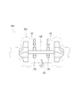
- the turbocharger 130 is a turbo-type supercharger, and is supported at both ends of the turbine shaft 134, a turbine shaft 134 disposed in the housing 132, two bearings 136 and 138 that support a midway portion of the turbine shaft 134. (See FIG. 2).
- the kind of supercharger is not limited to this embodiment, For example, you may be a mechanical supercharger which drives by transmitting the motive power of an engine.
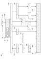
- the lubricating oil supply mechanism 1 supplies lubricating oil A1 and A2 to such an engine (cylinder block 110 and cylinder head 120) and the supercharger 130.
- the lubricating oil supply mechanism 1 includes a block side oil pan 10, a block side oil pump 12, a block side oil passage 14, a head side oil pan 20, a head side oil pump 22, a head side oil passage 24, and the like.
- the block-side oil pan 10 is attached to the lower part of the cylinder block 110.
- the block-side oil pan 10 stores lubricating oil A1.
- the block side oil pump 12 is disposed in the cylinder block 110 of the engine.
- the block-side oil pump 12 is configured by, for example, a tocoloid pump that is connected to the crankshaft 112 of the engine and is driven by the rotation of the crankshaft 112. That is, the block-side oil pump 12 is driven by the engine and is driven at a rotational speed corresponding to the rotational speed of the engine.
- a relief valve (not shown) for returning the lubricating oil A1 from the discharge side of the block side oil pump 12 to the suction side according to the discharge pressure of the block side oil pump 12 is provided in the block side oil pump 12. .
- the block-side oil pump 12 communicates with the block-side oil pan 10 via an oil strainer 10a and piping.
- the block side oil pump 12 is driven by the engine to suck the lubricating oil A1 from the block side oil pan 10 and pumps the lubricating oil A1 toward the crankshaft 112 of the cylinder block 110 and the like.
- the lubricating oil A1 pumped by the block-side oil pump 12 is supplied to a main oil hole (not shown) that is a hole formed in the cylinder block 110 via the oil filter 12a.
- the oil filter 12a is provided with a relief valve (not shown) for circulating the lubricating oil A1 when the oil filter 12a is clogged.
- Lubricating oil A1 supplied to the main oil hole of the cylinder block 110 is branched and supplied to members arranged in the cylinder block 110, such as the crankshaft 112, the piston 114, the chain tensioner 116, the timing chain 118, and the like. Is done.
- the cylinder block 110 is formed with a plurality of passages that branch out from the main oil hole toward the crankshaft 112, the piston 114, and the like.
- the lubricating oil A1 is supplied to the cylinder block 110 through the passages.
- Lubricating oil A ⁇ b> 1 is collected in the block-side oil pan 10 after being supplied to the cylinder block 110.
- an oil drop (not shown) is formed as a passage that extends from below the crankshaft 112 and the piston 114 toward the block-side oil pan 10 and opens above the block-side oil pan 10.
- the lubricating oil A1 is collected in the block-side oil pan 10 through the oil drop.
- the block-side oil passage 14 is a route of the lubricating oil A1 that is supplied from the block-side oil pan 10 to the crankshaft 112, the piston 114, and the like of the cylinder block 110 and then recovered to the block-side oil pan 10.
- the block-side oil passage 14 includes a pipe that connects the block-side oil pump 12 and the oil strainer 10a, a main oil hole of the cylinder block 110, each passage formed in the cylinder block 110, and an oil drop. Composed of etc.
- the block side oil passage 14 functions as a first oil passage for supplying the lubricating oil A1 to the cylinder block 110 of the engine.
- block-side oil pan 10 is disposed on the block-side oil passage 14 and functions as a first oil pan in which the lubricating oil A1 flowing through the block-side oil passage 14 is stored.
- the head-side oil pan 20 is attached to the same side as the side to which the engine supercharger 130 is attached, for example, and is disposed below the supercharger 130. That is, the head side oil pan 20 is attached to one side surface of the cylinder head 120 of the engine.
- the head-side oil pan 20 stores lubricating oil A2.
- the head side oil pump 22 is composed of a commercially available electric pump.
- the head-side oil pump 22 is electrically connected to, for example, an ECU (Engine Control Unit) and a battery (not shown) mounted on the vehicle, and is driven by applying a voltage from the battery by an electric signal from the ECU.
- ECU Engine Control Unit
- battery not shown
- the head-side oil pump 22 is arranged inside the head-side oil pan 20, more specifically, in a state where the head-side oil pan 20 is immersed in the lubricating oil A2 of the head-side oil pan 20.
- the head-side oil pump 22 communicates with an oil hole (not shown) that is a hole formed in the cylinder head 120 via a pipe or the like.
- the head-side oil pump 22 is driven to pump the lubricating oil A2 from the head-side oil pan 20 toward the cylinder head 120.
- the head-side oil pump 22 functions as an oil pump that pumps the lubricating oil A2 stored in the head-side oil pan 20.
- the lubricating oil A2 pumped by the head-side oil pump 22 is branched into members disposed in the cylinder head 120 through the oil holes of the cylinder head 120, such as the exhaust camshaft 122 and the intake camshaft 124, respectively. Supplied.
- the cylinder head 120 is formed with a plurality of passages that branch out from the oil hole and extend toward the exhaust cam shaft 122 and the intake cam shaft 124 of the cylinder head 120.
- the lubricating oil A2 is supplied to the cylinder head 120 through each passage.
- Lubricating oil A ⁇ b> 2 is collected in the head-side oil pan 20 after being supplied to the cylinder head 120.
- an oil drop (not shown) is formed as a passage extending from below the exhaust cam shaft 122 and the intake cam shaft 124 toward the head side oil pan 20 and communicating with the head side oil pan 20.
- the lubricating oil A2 is collected in the head-side oil pan 20 through the oil drop.
- the lubricating oil A ⁇ b> 2 pumped by the head side oil pump 22 passes through the oil hole of the cylinder head 120 and is disposed in the supercharger 130, for example, the housing 132.
- the two bearings 136 and 138 that support the turbine shaft 134 are also branched and supplied.
- the cylinder head 120 is formed with a passage (not shown) that branches from the oil hole toward the supercharger 130 and extends.
- the housing 132 of the supercharger 130 is formed with a passage (not shown) that communicates with the passage of the cylinder head 120 and branches and extends toward the bearings 136 and 138 and the like.
- the lubricating oil A2 is supplied to the supercharger 130 through the passages (see arrow A2 shown on the upper side of FIG. 2).
- Lubricating oil A ⁇ b> 2 is collected in the head-side oil pan 20 after being supplied to the supercharger 130.
- an oil drop (not shown) is formed as a passage that extends from below the bearings 136 and 138 toward the head-side oil pan 20 and opens above the head-side oil pan 20. ing.
- the lubricating oil A2 passes through the oil drop and is collected in the head-side oil pan 20 (see arrow A2 shown on the lower side of FIG. 2).
- the head-side oil passage 24 is a route of the lubricating oil A2 that is supplied from the head-side oil pan 20 to the cylinder head 120 and the supercharger 130 and then collected by the head-side oil pan 20.
- the head side oil passage 24 includes a pipe that connects the head side oil pump 22 and the cylinder head 120, an oil hole of the cylinder head 120, each passage of the cylinder head 120 and the supercharger 130, and oil. Composed by dropping.
- the head side oil passage 24 functions as a second oil passage for supplying the lubricating oil A2 to the supercharger 130.
- the head-side oil pan 20 is disposed on the head-side oil passage 24 and functions as a second oil pan in which the lubricating oil A2 flowing through the head-side oil passage 24 is stored.
- the head-side oil pan 20 is disposed below the supercharger 130.
- the lubricating oil supply mechanism 1 can return the lubricating oil A2 to the head-side oil pan 20 only by dropping the lubricating oil A2 that lubricates the bearings 136 and 138 of the supercharger 130 by its own weight.
- the lubricating oil supply mechanism 1 can recover the lubricating oil A2 efficiently (without being separately pumped to the head-side oil pan 20 by a pump or the like).
- the lubricant oil A1 when the lubricant oil A1 is supplied to the cylinder block 110, the lubricant oil A1 contains a lot of sludge.
- the lubricating oil supply mechanism 1 does not supply one oil pan lubricating oil to the cylinder block 110 and the supercharger 130 by branching one oil passage, but two independent oils.
- the lubricating oils A1 and A2 of the two oil pans 10 and 20 are separately supplied from the paths 14 and 24.
- the lubricating oil supply mechanism 1 divides the lubricating oil passage into two parts so that the lubricating oil A1 supplied to the cylinder block 110 is not supplied to the supercharger 130. Yes.
- the lubricating oil supply mechanism 1 supplies the lubricating oil A1 containing a large amount of sludge only to the cylinder block 110. That is, the lubricating oil supply mechanism 1 can supply the supercharger 130 with the lubricating oil A2 that does not contain much sludge.
- the lubricating oil supply mechanism 1 can effectively lubricate the bearings 136 and 138 that support the turbine shaft 134 of the supercharger 130, and can suppress the occurrence of coking in the bearings 136 and 138.
- the lubricating oil supply mechanism 1 can improve the oxidation deterioration resistance of the lubricating oil A2 supplied to the supercharger 130.
- the lubricating oil supply mechanism 1 can improve the mechanical efficiency of the supercharger 130.
- the lubricating oil supply mechanism 1 configures the block side oil passage 14 and the head side oil passage 24 as independent oil passages.
- the head-side oil pump 22 is disposed in a state of being immersed in the lubricating oil A2 stored in the head-side oil pan 20.
- the lubricating oil supply mechanism 1 warms the lubricating oil A2 of the head side oil pan 20 by utilizing the heat generated by the head side oil pump 22 when driving the engine placed in a low temperature environment. be able to.
- the lubricating oil supply mechanism 1 can quickly reduce the viscosity of the lubricating oil A2 even in a low temperature environment, the friction of the supercharger 130 can be reduced.
- the oil pump according to the present invention does not suck air in the second oil pan (head-side oil pan 20 according to the present embodiment) during driving. What is necessary is just to be immersed in the lubricating oil of a 2nd oil pan.
- the “state immersed in the lubricating oil A2” indicates a state where the suction port of the head side oil pump 22 is immersed in the lubricating oil A2 when the head side oil pump 22 is driven. Accordingly, the head-side oil pump 22 does not necessarily have to be entirely immersed in the lubricating oil A2 of the head-side oil pan 20 during driving. For example, the upper end portion may protrude from the oil surface during driving. .
- the lubricating oil supply mechanism 1 employs an electric oil pump as such a head-side oil pump 22.
- the head side oil pump 22 can pump the amount of the lubricating oil A2 according to the applied voltage.
- the head-side oil pump 22 can stably supply the lubricating oil A2 to the supercharger 130 regardless of the rotational speed of the crankshaft 112, that is, the operating state of the engine. That is, the head-side oil pump 22 can always supply the lubricating oil A2 adjusted to an appropriate amount to the supercharger 130.
- the lubricating oil supply mechanism 1 can reduce the friction of the supercharger 130, the mechanical efficiency of the supercharger 130 can be effectively improved.
- the lubricating oil supply mechanism 1 can cool the head-side oil pump 22 by the lubricating oil A2 stored in the head-side oil pan 20. Therefore, the lubricating oil supply mechanism 1 can improve the cooling efficiency of the head-side oil pump 22.
- the lubricating oil supply mechanism 1 has a seal for preventing the lubricating oil A2 from leaking to the head side oil pump 22 as compared with the case where the head side oil pump 22 is arranged at a position away from the head side oil pan 20. There is no need to attach a member.
- the lubricating oil supply mechanism 1 can improve the mechanical efficiency of the supercharger 130 by disposing the electric head-side oil pump 22 soaked in the lubricating oil A2 of the head-side oil pan 20.
- the life of the head-side oil pump 22 can be extended and the number of parts can be reduced.
- the lubricating oil supply mechanism 1 also supplies the cylinder head 120 with the lubricating oil A2 that lubricates the supercharger 130.
- the lubricating oil supply mechanism 1 can supply the cylinder head 120 with the lubricating oil A2 that does not contain much sludge. For this reason, the lubricating oil supply mechanism 1 can effectively lubricate the exhaust camshaft 122, the intake camshaft 124, and the like of the cylinder head 120.
- the lubricating oil supply mechanism 1 can improve the oxidation deterioration resistance of the lubricating oil A2 supplied to the cylinder head 120.
- the lubricating oil supply mechanism 1 can improve the mechanical efficiency of members (for example, the exhaust camshaft 122 and the intake camshaft 124) disposed in the cylinder head 120.
- the head side oil passage 24 is formed as an oil passage for supplying the lubricating oil A2 stored in the head side oil pan 20 to the cylinder head 120 of the engine.
- the configuration of the lubricating oil supply mechanism is not limited to the present embodiment as long as the lubricating oil passage supplied to the cylinder block and the lubricating oil supply passage supplied to the supercharger are isolated from each other. .
- the lubricating oil supply mechanism includes a first oil passage 214 that supplies the lubricating oil A 201 to the cylinder block 110 and the cylinder head 120, as in the lubricating oil supply mechanism 201 according to another embodiment shown in FIG.
- a second oil passage 224 for supplying the lubricating oil A202 only to the machine 130 may be provided.
- the present invention can be applied to a lubricating oil supply mechanism that supplies lubricating oil to an engine and a supercharger attached to the engine.
- Lubricating oil supply mechanism 10 Block side oil pan (first oil pan) 14 Block side oil passage (first oil passage) 20 Head side oil pan (second oil pan) 24 Head side oil passage (second oil passage) 110 Cylinder block 130 Supercharger A1 Lubricating oil (lubricating oil flowing through the first oil passage) A2 Lubricating oil (Lubricating oil flowing through the second oil passage)
Landscapes
- Engineering & Computer Science (AREA)
- Mechanical Engineering (AREA)
- General Engineering & Computer Science (AREA)
- Chemical & Material Sciences (AREA)
- Combustion & Propulsion (AREA)
- Lubrication Of Internal Combustion Engines (AREA)
- Lubrication Details And Ventilation Of Internal Combustion Engines (AREA)
- Supercharger (AREA)
Abstract
L'invention concerne un mécanisme d'alimentation en huile de graissage qui peut améliorer l'efficacité mécanique d'un compresseur d'alimentation. Un mécanisme d'alimentation en huile de graissage (1) qui fournit de l'huile de graissage (A1, A2) à un moteur et à un compresseur d'alimentation (130) qui est fixé sur le moteur, et qui comporte un trajet d'huile côté bloc (14) qui est destiné à fournir l'huile de graissage (A1) à un bloc-cylindres (110) du moteur, un carter d'huile côté bloc (10) qui est agencé le long de l'itinéraire du trajet d'huile côté bloc (14) et qui collecte l'huile de graissage (A1) qui s'écoule dans le trajet d'huile côté bloc (14), un trajet d'huile côté tête (24) qui est destiné à fournir l'huile de graissage (A2) au compresseur d'alimentation (130) et un carter d'huile côté tête (20) qui est agencé le long de l'itinéraire du trajet d'huile côté tête (24) et qui collecte l'huile de graissage (A2) qui s'écoule dans le trajet d'huile côté tête. (24). Le trajet d'huile côté bloc (14) et le trajet d'huile côté tête (24) sont configurés en tant que trajets d'huile indépendants.
Priority Applications (3)
| Application Number | Priority Date | Filing Date | Title |
|---|---|---|---|
| US15/112,874 US20160341081A1 (en) | 2014-03-14 | 2015-03-09 | Lubricant feed mechanism |
| CN201580013407.0A CN106103922A (zh) | 2014-03-14 | 2015-03-09 | 润滑油供给机构 |
| EP15761769.7A EP3118428A4 (fr) | 2014-03-14 | 2015-03-09 | Mécanisme d'alimentation en huile de graissage |
Applications Claiming Priority (2)
| Application Number | Priority Date | Filing Date | Title |
|---|---|---|---|
| JP2014051540A JP6259688B2 (ja) | 2014-03-14 | 2014-03-14 | 潤滑油供給機構 |
| JP2014-051540 | 2014-03-14 |
Publications (1)
| Publication Number | Publication Date |
|---|---|
| WO2015137273A1 true WO2015137273A1 (fr) | 2015-09-17 |
Family
ID=54071718
Family Applications (1)
| Application Number | Title | Priority Date | Filing Date |
|---|---|---|---|
| PCT/JP2015/056805 Ceased WO2015137273A1 (fr) | 2014-03-14 | 2015-03-09 | Mécanisme d'alimentation en huile de graissage |
Country Status (5)
| Country | Link |
|---|---|
| US (1) | US20160341081A1 (fr) |
| EP (1) | EP3118428A4 (fr) |
| JP (1) | JP6259688B2 (fr) |
| CN (1) | CN106103922A (fr) |
| WO (1) | WO2015137273A1 (fr) |
Cited By (3)
| Publication number | Priority date | Publication date | Assignee | Title |
|---|---|---|---|---|
| WO2017081123A1 (fr) * | 2015-11-13 | 2017-05-18 | Total Marketing Services | Méthode de lubrification séparée d'un système de motorisation pour véhicule automobile |
| WO2017081142A1 (fr) * | 2015-11-13 | 2017-05-18 | Total Marketing Services | Système de motorisation et véhicule automobile associé |
| WO2018037101A1 (fr) * | 2016-08-26 | 2018-03-01 | Total Marketing Services | Système de motorisation et procédé de lubrification et de refroidissement associé |
Families Citing this family (4)
| Publication number | Priority date | Publication date | Assignee | Title |
|---|---|---|---|---|
| JP6142885B2 (ja) * | 2015-03-05 | 2017-06-07 | マツダ株式会社 | エンジンのオイル供給装置、エンジンの製造方法及びエンジンの給油路構造 |
| JP6631590B2 (ja) * | 2017-05-31 | 2020-01-15 | トヨタ自動車株式会社 | 内燃機関のオイル循環装置 |
| JP6669131B2 (ja) * | 2017-05-31 | 2020-03-18 | トヨタ自動車株式会社 | 内燃機関のオイル循環装置 |
| DE102017114609A1 (de) * | 2017-06-30 | 2019-01-03 | Man Diesel & Turbo Se | Abgasturbolader mit gekammertem Ölverteilerraum |
Citations (4)
| Publication number | Priority date | Publication date | Assignee | Title |
|---|---|---|---|---|
| JPS56171635U (fr) * | 1980-05-22 | 1981-12-18 | ||
| JPS604705U (ja) * | 1983-06-23 | 1985-01-14 | 日産自動車株式会社 | 内燃機関のバルブリフト制御装置 |
| JPH11257585A (ja) * | 1997-12-15 | 1999-09-21 | Caterpillar Inc | エンジン |
| JP2009074394A (ja) * | 2007-09-19 | 2009-04-09 | Toyota Central R&D Labs Inc | 内燃機関 |
Family Cites Families (3)
| Publication number | Priority date | Publication date | Assignee | Title |
|---|---|---|---|---|
| JPS62193140U (fr) * | 1986-05-30 | 1987-12-08 | ||
| JPH08270428A (ja) * | 1995-03-29 | 1996-10-15 | Toyota Motor Corp | 内燃機関の潤滑装置 |
| CN1632293A (zh) * | 2004-12-20 | 2005-06-29 | 粱文利 | 用于涡轮增压器的供油装置 |
-
2014
- 2014-03-14 JP JP2014051540A patent/JP6259688B2/ja not_active Expired - Fee Related
-
2015
- 2015-03-09 CN CN201580013407.0A patent/CN106103922A/zh active Pending
- 2015-03-09 EP EP15761769.7A patent/EP3118428A4/fr not_active Withdrawn
- 2015-03-09 WO PCT/JP2015/056805 patent/WO2015137273A1/fr not_active Ceased
- 2015-03-09 US US15/112,874 patent/US20160341081A1/en not_active Abandoned
Patent Citations (4)
| Publication number | Priority date | Publication date | Assignee | Title |
|---|---|---|---|---|
| JPS56171635U (fr) * | 1980-05-22 | 1981-12-18 | ||
| JPS604705U (ja) * | 1983-06-23 | 1985-01-14 | 日産自動車株式会社 | 内燃機関のバルブリフト制御装置 |
| JPH11257585A (ja) * | 1997-12-15 | 1999-09-21 | Caterpillar Inc | エンジン |
| JP2009074394A (ja) * | 2007-09-19 | 2009-04-09 | Toyota Central R&D Labs Inc | 内燃機関 |
Cited By (8)
| Publication number | Priority date | Publication date | Assignee | Title |
|---|---|---|---|---|
| WO2017081123A1 (fr) * | 2015-11-13 | 2017-05-18 | Total Marketing Services | Méthode de lubrification séparée d'un système de motorisation pour véhicule automobile |
| WO2017081142A1 (fr) * | 2015-11-13 | 2017-05-18 | Total Marketing Services | Système de motorisation et véhicule automobile associé |
| FR3043718A1 (fr) * | 2015-11-13 | 2017-05-19 | Total Marketing Services | Methode de lubrification separee d'un systeme de motorisation pour vehicule automobile |
| FR3043717A1 (fr) * | 2015-11-13 | 2017-05-19 | Total Marketing Services | Systeme de motorisation et vehicule automobile associe |
| CN108350773A (zh) * | 2015-11-13 | 2018-07-31 | 道达尔销售服务公司 | 用于对机动车辆的驱动系统进行单独润滑的方法 |
| US10513953B2 (en) | 2015-11-13 | 2019-12-24 | Total Marketing Services | Drive system and associated motor vehicle |
| WO2018037101A1 (fr) * | 2016-08-26 | 2018-03-01 | Total Marketing Services | Système de motorisation et procédé de lubrification et de refroidissement associé |
| FR3055359A1 (fr) * | 2016-08-26 | 2018-03-02 | Total Marketing Services | Systeme de motorisation, haut-moteur et procede de lubrification et de refroidissement associe |
Also Published As
| Publication number | Publication date |
|---|---|
| US20160341081A1 (en) | 2016-11-24 |
| JP6259688B2 (ja) | 2018-01-10 |
| JP2015175272A (ja) | 2015-10-05 |
| EP3118428A1 (fr) | 2017-01-18 |
| EP3118428A4 (fr) | 2017-11-29 |
| CN106103922A (zh) | 2016-11-09 |
Similar Documents
| Publication | Publication Date | Title |
|---|---|---|
| JP6259688B2 (ja) | 潤滑油供給機構 | |
| US8303359B2 (en) | Outboard motor | |
| JP5632049B1 (ja) | 無段変速機の制御用油圧回路 | |
| JP6436289B2 (ja) | クランクシャフトの支持部構造 | |
| WO2006000269A8 (fr) | Moteur a combustion interne a lubrification par circulation forcee selon le principe de la lubrification a carter sec | |
| JP2010203347A (ja) | 過給機の潤滑装置 | |
| US20190162182A1 (en) | Gear Pump That Removes Air From Pumped Oil | |
| KR101081104B1 (ko) | 오일펌프의 분리형 아이들러 기어 샤프트 어셈블리 | |
| CN102052118A (zh) | 包括次油泵和泵安装结构的发动机组件 | |
| CN106321187A (zh) | 一种发动机、发动机润滑系统及发动机润滑方法 | |
| JP5578050B2 (ja) | エンジンのオイルポンプ配置構造 | |
| JP2011075010A (ja) | パワーユニット | |
| JP2011127443A (ja) | 内燃機関の潤滑装置 | |
| JP2010071221A (ja) | エンジン構造 | |
| JP7189838B2 (ja) | 発電機能付きエンジンユニット | |
| US20170044972A1 (en) | Bearing housing body assembly of an exhaust-gas turbocharger | |
| CN101598045A (zh) | 发动机组 | |
| WO2013176939A1 (fr) | Circuit d'huile de grande efficacité | |
| GB2591272A (en) | Internal combustion engine for a vehicle | |
| RU2555920C2 (ru) | Маслоснабжающее устройство | |
| KR100410497B1 (ko) | 자동차의 윤활장치 | |
| JP4323897B2 (ja) | 内燃機関の潤滑装置 | |
| JP6327055B2 (ja) | エンジンの潤滑オイル供給構造 | |
| TR200806401U (tr) | İlk çalışma öncesi pilot yağlama. | |
| JP2019105186A (ja) | エンジンのオイル供給システム |
Legal Events
| Date | Code | Title | Description |
|---|---|---|---|
| 121 | Ep: the epo has been informed by wipo that ep was designated in this application |
Ref document number: 15761769 Country of ref document: EP Kind code of ref document: A1 |
|
| REEP | Request for entry into the european phase |
Ref document number: 2015761769 Country of ref document: EP |
|
| WWE | Wipo information: entry into national phase |
Ref document number: 2015761769 Country of ref document: EP |
|
| WWE | Wipo information: entry into national phase |
Ref document number: 15112874 Country of ref document: US |
|
| NENP | Non-entry into the national phase |
Ref country code: DE |