WO2015137277A1 - 磁気センサー - Google Patents
磁気センサー Download PDFInfo
- Publication number
- WO2015137277A1 WO2015137277A1 PCT/JP2015/056826 JP2015056826W WO2015137277A1 WO 2015137277 A1 WO2015137277 A1 WO 2015137277A1 JP 2015056826 W JP2015056826 W JP 2015056826W WO 2015137277 A1 WO2015137277 A1 WO 2015137277A1
- Authority
- WO
- WIPO (PCT)
- Prior art keywords
- magnetization
- ferromagnetic metal
- free layer
- magnetic field
- magnetic
- Prior art date
- Legal status (The legal status is an assumption and is not a legal conclusion. Google has not performed a legal analysis and makes no representation as to the accuracy of the status listed.)
- Ceased
Links
Images


Classifications
-
- G—PHYSICS
- G01—MEASURING; TESTING
- G01R—MEASURING ELECTRIC VARIABLES; MEASURING MAGNETIC VARIABLES
- G01R33/00—Arrangements or instruments for measuring magnetic variables
- G01R33/02—Measuring direction or magnitude of magnetic fields or magnetic flux
- G01R33/06—Measuring direction or magnitude of magnetic fields or magnetic flux using galvano-magnetic devices
- G01R33/09—Magnetoresistive devices
- G01R33/098—Magnetoresistive devices comprising tunnel junctions, e.g. tunnel magnetoresistance sensors
Definitions
- the present invention relates to a magnetic sensor suitable for sensing a weak magnetic field.
- TMR tunnel magnetoresistive element
- the tunnel magnetoresistive element includes a ferromagnetic metal magnetization fixed layer whose magnetization direction is fixed, a ferromagnetic metal magnetization free layer whose magnetization direction changes under the influence of an external magnetic field, and a ferromagnetic metal magnetization fixed layer And an insulating layer disposed between the ferromagnetic metal magnetization free layer and insulating by a tunnel effect according to the angular difference between the magnetization direction of the ferromagnetic metal magnetization fixed layer and the magnetization direction of the ferromagnetic metal magnetization free layer Change the resistance of the layer.
- the invention described in Patent Document 1 has an easy magnetization axis of a ferromagnetic metal magnetization free layer with a detection magnetic field of zero in order to achieve high sensitivity. It is characterized by being in a twisted position with respect to the easy magnetization axis of the metal magnetization fixed layer.
- the resistance changes proportionally up and down according to changes in the positive magnetic field and the negative magnetic field from the zero detection magnetic field (neutral position). It is required to wake up.
- the easy magnetization axis of the free layer at zero detection magnetic field is in a twisted position with respect to the easy magnetization axis of the fixed layer.
- the resistance can be changed proportionally up and down. In this case, as shown in FIG.
- the TMR element exhibits a resistance change according to the strength of the magnetic field in the direction Y2 orthogonal to the direction Y1 of the magnetization of the free layer 104 in a state where the detection magnetic field is zero. Used to detect the magnetic field in the direction Y2.
- the sensitivity can be expressed as a resistance change rate of the TMR element / 2Hk.
- 2Hk corresponds to a magnetic field necessary for reversing the magnetization direction of the free layer in the difficult magnetization axis direction. Therefore, it has been considered to increase the sensitivity by reducing 2Hk and increasing the resistance change rate of the TMR element.
- the state in which the magnetization direction Y1 is oriented in the easy magnetization axis direction (G3 in FIG. 9) and the resistance change with respect to the magnetic field before and after that Shows a linear change characteristic, but shows a non-linear change in the vicinity of the state (G2 or G4 in FIG. 9) in which the magnetization direction Y1 is oriented in the direction of the difficult magnetization axis, which is a reliable magnetic field measurement.
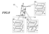
- the resistance value at the detection magnetic field zero is stable at the upper limit value or the lower limit value of the resistance, and the magnetic field from the detection magnetic field zero is It was thought that the change could not be measured (see G1 in FIG. 8).
- the present invention has been made in view of the above problems in the prior art, and in a magnetic sensor using a tunnel magnetoresistive element, it is possible to achieve high sensitivity and to measure a weak magnetic change with high accuracy.
- An object is to provide a magnetic sensor.
- the invention described in claim 1 for solving the above-described problems is a ferromagnetic metal magnetization fixed layer in which the magnetization direction is fixed, and the ferromagnetic metal magnetization free in which the magnetization direction changes under the influence of an external magnetic field.
- an insulating layer disposed between the ferromagnetic metal magnetization fixed layer and the ferromagnetic metal magnetization free layer, the magnetization direction of the ferromagnetic metal magnetization fixed layer and the ferromagnetic metal magnetization free
- a magnetic sensor including a tunnel magnetoresistive element that changes a resistance of the insulating layer by a tunnel effect according to an angle difference with a magnetization direction of the layer, By controlling a magnetic field generation source that changes the magnetization direction of the ferromagnetic metal magnetization free layer, the magnetization direction of the ferromagnetic metal magnetization free layer is rotated from the easy magnetization axis of the ferromagnetic metal magnetization free layer.
- a feedback circuit that stabilizes the ferromagnetic metal magnetization fixed layer at a twist position having a predetermined twist angle with respect to the easy magnetization axis of the ferromagnetic metal magnetization fixed layer
- the magnetic sensor is characterized in that a fluctuating detected magnetic signal is output from the feedback circuit.
- the “twisted position” refers to a positional relationship in which two straight lines in the space are not parallel and do not intersect, that is, a positional relationship between two straight lines that cannot exist on the same plane.
- a straight line perpendicular to the two straight lines at the position of twist is called “twist axis”, and the relative angle of the other straight line to one straight line around the twist axis is called “twist angle”.
- the invention according to claim 2 stabilizes the feedback circuit so that the torsion angle is not affected by disturbance outside the fluctuation frequency range of the detected magnetic signal, 2.
- the feedback circuit is stabilized so that the torsion angle is not affected by disturbance including a fluctuation frequency range of the detected magnetic signal, 2.
- the invention according to claim 4 is characterized in that the easy magnetization axis of the ferromagnetic metal magnetization free layer is parallel to the easy magnetization axis of the ferromagnetic metal magnetization fixed layer. It is a magnetic sensor as described in any one of these.
- the feedback circuit applies a magnetic field from the magnetic field generation source in the direction of the hard magnetization axis of the ferromagnetic metal magnetization free layer to change the magnetization direction of the ferromagnetic metal magnetization free layer.
- the feedback circuit applies a magnetic field from the magnetic field generation source in the direction of the easy magnetization axis of the ferromagnetic metal magnetization free layer to change the magnetization direction of the ferromagnetic metal magnetization free layer.
- the invention according to claim 7 is the magnetic sensor according to any one of claims 1 to 6, wherein the predetermined twist angle is between 45 degrees and 135 degrees.
- the invention according to claim 8 is the magnetic sensor according to any one of claims 1 to 7, wherein the insulating layer is made of MgO.
- the magnetic field generation source that changes the magnetization direction of the free layer is controlled, and the magnetization direction of the free layer is rotated from the easy magnetization axis of the free layer so as to be the easy magnetization axis of the fixed layer.
- a neutral position for detecting magnetism zero point in measurement
- the detection magnetic signal can be output by extracting from a control signal for controlling the magnetic field generation source of the feedback circuit.
- the direction of magnetization of the free layer and the easy magnetization axis of the fixed layer have a predetermined twist angle, so that the resistance change of the tunnel magnetoresistive element with respect to the magnetic field shows a linear change characteristic Magnetism can be measured in the region, high sensitivity is achieved, and weak magnetic changes can be measured with high accuracy.
- a magnetic field from a magnetic field generation source is applied in the direction of the easy magnetization axis of the free layer to stabilize the magnetization direction of the free layer at a twisted position having a predetermined twist angle and to be in a neutral position.
- the resistance change with respect to the magnetic field of the tunnel magnetoresistive element becomes remarkable, and the sensitivity can be significantly increased.
- FIG. 4 is a schematic perspective view showing an HR characteristic curve of a TMR element and a state of magnetization directions of the TMR element at three points on the characteristic curve according to one embodiment of the present invention.
- FIG. 4 is a schematic perspective view showing an HR characteristic curve of a TMR element and a state of magnetization directions of the TMR element at three points on the characteristic curve according to one embodiment of the present invention.
- FIG. 10 is a schematic perspective view showing an HR characteristic curve of a TMR element and a state of a magnetization direction of the TMR element at three points on the characteristic curve according to a conventional example.
- FIG. 1 shows an example of a laminated structure of a TMR module 1 in which two TMR elements are configured.
- the TMR module 1 includes a base layer 3, a ferromagnetic metal magnetization free layer 4, an insulating layer 5, a ferromagnetic metal magnetization fixed layer 6, a pinned layer 7, a buffer layer 8, an upper part on a silicon substrate 2. It has a laminated structure in which the electrode layers 9 are sequentially laminated.
- the ferromagnetic metal magnetization free layer 4 includes a soft magnetic layer 41, a barrier layer 42, and a ferromagnetic layer 43.
- the ferromagnetic metal magnetization fixed layer 6 includes a ferromagnetic layer 61, a barrier layer 62, and a ferromagnetic layer 63.
- the ferromagnetic metal magnetization fixed layer 6, the pinned layer 7, the buffer layer 8, and the upper electrode layer constitute two upper stacked bodies 11 and 12 that are independent of each other.
- the ferromagnetic metal magnetization fixed layer 6 formed in one upper laminate 11, the insulating layer 5 therebelow, and the ferromagnetic metal magnetization free layer 4 constitute one TMR element.
- one TMR element is constituted by the ferromagnetic metal magnetization fixed layer 6 formed in the other upper laminated body 12, the insulating layer 5 therebelow, and the ferromagnetic metal magnetization free layer 4.
- TMR module 1 By connecting one of the anode side and the cathode side of the applied voltage to the upper electrode layer 9 configured in the upper laminate 11 and connecting the other to the upper electrode layer 9 configured in the upper laminate 12, These two TMR elements are used in series. Further, by connecting a plurality of TMR modules 1 in series, four or more TMR elements can be used in series. However, the structure of the TMR module 1 described above is merely an example, and by providing the lower electrode layer on the base of the ferromagnetic metal magnetization free layer 4, it can be applied from one TMR element as a minimum unit.
- the insulating layer 5 is disposed between the ferromagnetic metal magnetization fixed layer 6 and the ferromagnetic metal magnetization free layer 4.
- various insulating materials can be used.
- MgO, AlOx, or the like can be used. From the viewpoint of improving the sensitivity of the element, MgO is preferable.
- MgO film in order to detect a weak magnetic field such as a biomagnetic signal by the TMR element, it is preferable to use an MgO film as the insulating layer 5.
- the thickness of the insulating layer 5 is desirably about 1 nm to 10 nm.
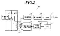
- a bridge is configured as shown in FIG. 2 or FIG. 3, and a magnetic center 10A or 10B including a feedback circuit is configured.
- the constant resistance R1 and the constant resistance R2 are connected in series, and the constant resistance R3 and the TMR module 1 are connected in series between the electrodes to which the reference voltage V1 is applied.
- An electrode between the constant resistance R1 and the constant resistance R2 and an electrode between the constant resistance R3 and the TMR module 1 are taken out by the instrumentation amplifier a1, and the instrumentation amplifier a1 detects a potential difference between these electrodes, and a voltage amplifier Output to a2.
- the magnetic center 10A shown in FIG. 2 further has the following configuration.
- the output signal of the voltage amplifier a2 is output to the low pass filter a3 and the buffer circuit a7.
- the output signal of the low-pass filter a3 is compared with the reference value by the comparator a4, and a control signal corresponding to the comparison result with the reference value is output to the power amplifier a5.
- the power amplifying unit a5 Based on the control signal, the power amplifying unit a5 generates electric power for causing a current to flow through the magnetic field generating coil a6, and applies a magnetic field to the TMR module 1 by the magnetic field generating coil a6.
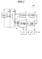
- the magnetic center 10B shown in FIG. 3 further has the following configuration.
- the output signal of the voltage amplifier a2 is compared with a reference value by the comparator a4, and a control signal corresponding to the comparison result with the reference value is output to the power amplifier a5.
- the power amplifying unit a5 Based on the control signal, the power amplifying unit a5 generates electric power for causing a current to flow through the magnetic field generating coil a6, and applies a magnetic field to the TMR module 1 by the magnetic field generating coil a6.
- the magnetic field generating coil a6 is a magnetic field generating source that changes the magnetization direction of the ferromagnetic metal magnetization free layer 4.
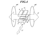
- FIG. 4 schematically shows the free layer 4 and the fixed layer 6.
- the illustration of the insulating layer between the free layer 4 and the fixed layer 6 is omitted.
- the magnetization direction c2 coincides with the easy magnetization axis c1 direction, and the magnetization direction c2 is fixed.
- a TMR element in which the easy magnetization axis c4 of the free layer 4 is parallel to the easy magnetization axis c1 is applied.
- the magnetization direction c5 before application of the control magnetic field c3 coincides with the easy magnetization axis c4.
- the free layer 4 rotates from the easy magnetization axis c4 by application of the control magnetic field c3 substantially orthogonal to the easy magnetization axis c4.
- the magnetization direction c6 is in a direction substantially perpendicular to the easy magnetization axis c4.
- the position of this twist is a neutral position for detecting magnetism.
- the control magnetic field c3 is a magnetic field generated by the above-described magnetic field generation coil a6, and is controlled by a feedback circuit including a comparator a4 with a reference value.
- the magnetic field generating coil a6 is denoted by reference numeral a61 in FIGS. 4, 5, and 6A.
- a configuration in which the free layer 4 is surrounded by a coil a63 shown in FIG. 6C can be given.
- Each magnetic field line is indicated by a line with an arrow.
- a reference value is set to form the neutral position as described above. That is, the reference value is set so that the difference between the signal input to the comparator a4 and the reference value becomes zero in the neutral position. If a difference occurs between the signal input to the comparator a4 and the reference value, feedback control is performed so that the difference converges to zero, that is, the magnetization direction c6 of the free layer 4 is stabilized at the neutral position.
- the direction (c7) perpendicular to the magnetization direction c6 at the neutral position is the direction of the detected magnetic field. That is, the magnetic sensors 10A and 10B detect the strength of the magnetic field in the direction of the detection axis c7. As can be seen from FIG.
- the feedback circuit of the magnetic sensors 10 ⁇ / b> A and 10 ⁇ / b> B applies the magnetic field c ⁇ b> 3 from the magnetic field generating coil a ⁇ b> 61 in the direction of the hard magnetization axis of the free layer 4.
- the direction c6 is stabilized at a twisted position having a predetermined twist angle.
- the neutral position shown in FIG. 4 is referred to as “neutral position forced by a control magnetic field in the direction of the hard magnetization axis”.
- FIG. 5 shows a configuration in which the is stabilized at a twisted position having a predetermined twist angle. That is, in FIG. 4, the easy magnetization axes c1 and c4 are orthogonal to the control magnetic field c3, but in FIG. 5, the easy magnetization axes c1 and c4 are arranged so as to coincide with the direction of the control magnetic field c3.
- the neutral position shown in FIG. 5 is referred to as a “neutral position forced by a control magnetic field in the direction of the easy magnetization axis”.
- the above-mentioned “neutral position forced by the control magnetic field in the direction of the difficult magnetization axis” (FIG. 4) is the state at the point (H0, R0) on the HR characteristic curve G1 of the TMR element shown in FIG. It corresponds to.
- H0 is a magnetic field generated by the magnetic field generating coil a61.
- the magnetization direction c6 of the free layer 4 swings as indicated by arc arrows d1 and d2 in G3 of FIG.
- the fact that the magnetization direction c6 of the free layer 4 oscillates in the direction of the circular arc arrow d1 indicates that the slope from the point (H0, R0) as shown by the linear arrow d1 on the HR characteristic curve G1 of the TMR element shown in FIG. If it shakes greatly, it corresponds to approaching the state shown in the inset G4 from the state shown in the inset G3. On the contrary, the magnetization direction c6 of the free layer 4 fluctuates in the direction of the circular arc arrow d2 as indicated by the straight line arrow d2 (H0, R0) on the HR characteristic curve G1 of the TMR element shown in FIG. From the state shown in the inset G3 to the state shown in the inset G2.
- the above-mentioned “neutral position forced by the control magnetic field in the direction of the easy magnetization axis” (FIG. 5) is the state at the point (H0, R0) on the HR characteristic curve G1 of the TMR element shown in FIG. It corresponds to.
- H0 is a magnetic field generated by the magnetic field generating coil a61.
- the magnetization direction c6 of the free layer 4 swings as indicated by arc arrows d1 and d2 in G3 of FIG.
- the fact that the magnetization direction c6 of the free layer 4 oscillates in the direction of the circular arc arrow d1 indicates that the slope from the point (H0, R0) as shown by the linear arrow d1 on the HR characteristic curve G1 of the TMR element shown in FIG. If it shakes greatly, it corresponds to approaching the state shown in the inset G4 from the state shown in the inset G3.
- the magnetization direction c6 of the free layer 4 fluctuates in the direction of the circular arc arrow d2 as indicated by the straight line arrow d2 (H0, R0) on the HR characteristic curve G1 of the TMR element shown in FIG. From the state shown in the inset G3 to the state shown in the inset G2.
- the vertical axis R represents the resistance of the TMR element
- the horizontal axis H represents the external magnetic field acting on the TMR element.
- Inset G2 shows magnetization directions C2 and C6 in a parallel state
- inset G4 shows magnetization directions C2 and C6 in an antiparallel state
- inset G3 shows a state in which magnetization directions C2 and C6 are twisted to a neutral position.
- the resistance R is the lower limit Rb when the magnetization directions C2 and C6 are parallel
- the resistance R is the upper limit Ra when the magnetization directions C2 and C6 are antiparallel.
- the magnetic sensors 10A and 10B are applied to a test object in a biomagnetic signal such as brain magnetism or a non-destructive test apparatus and leak from the test object.
- a magnetic signal forming a pulse waveform of a predetermined frequency can be measured.
- magnetic field fluctuations that gradually change due to disturbances such as temperature changes are removed so as not to be detected.
- a large number of magnetic sensors 10A and 10B are arranged on the outer surface of a living body such as a cranium to be measured and the outer surface of an object to be inspected in a nondestructive inspection apparatus such as a pipe or a wall so that the detection values of each sensor can be mapped. Configure and implement the measurement system.
- the signal is output as a detected magnetic signal via the instrumentation amplifier a1, the voltage amplifier a2, and the buffer circuit a7.
- the cut-off frequency of the low-pass filter a3 it is possible to detect a magnetic signal to be measured by eliminating disturbances such as temperature changes.
- the feedback circuit of the magnetic sensor 10A stabilizes the twist angle between the magnetization directions C2 and C6 so that the twist angle between the magnetization directions C2 and C6 is not affected by the disturbance outside the fluctuation frequency range of the detected magnetic signal. Then, the magnetic sensor 10A outputs a signal corresponding to the fluctuation of the twist angle in the fluctuation frequency range of the detection magnetic signal as the detection magnetic signal.
- the magnetic sensor 10B shown in FIG. 3 since no filter is provided between the TMR module 1 and the comparator a4, the magnetization directions C2 and C6 are caused by disturbance including the fluctuation frequency range of the detected magnetic signal.
- the torsion angle is stabilized at the neutral position indicated by the point (H0, R0).
- the magnetic sensor 10B passes a relatively high-frequency signal component from the control signal for controlling the magnetic field generating coil a6 through the high-pass filter b1, and outputs it as a detected magnetic signal via the buffer circuit b2.
- the cut-off frequency of the high-pass filter b1 it is possible to detect a magnetic signal to be measured by excluding a signal component due to a disturbance such as a temperature change.
- the feedback circuit of the magnetic sensor 10B stabilizes the twist angle between the magnetization directions C2 and C6 so as not to be affected by the disturbance including the fluctuation frequency range of the detected magnetic signal. Then, the magnetic sensor 10B extracts a signal in the fluctuation frequency range of the detected magnetic signal from the control signal for controlling the magnetic field generation source, and outputs it as a detected magnetic signal.
- a region showing a linear change characteristic including the point (H0, R0). can be used to measure magnetism, achieve high sensitivity, and measure weak magnetic changes with high accuracy.
- the predetermined twist angle with respect to the easy magnetization axis of the fixed layer in the magnetization direction of the free layer at the neutral position may be between 45 degrees and 135 degrees. preferable. More preferably, it is 60 to 120 degrees. In particular, as shown in FIG.
- a magnetic field from a magnetic field generation source is applied in the direction of the easy magnetization axis c4 of the free layer 4 to stabilize the magnetization direction of the free layer 4 at a twisted position having a predetermined twist angle.
- the resistance change with respect to the magnetic field of the TMR element becomes significant as shown in FIG. 8, and the sensitivity can be significantly increased. That is, in the HR characteristic with high hysteresis as shown in FIG. 8, the change in the magnetization direction of the free layer, and hence the resistance change is very abrupt. 8) can be taken to the point (H0, R0) on the steep slope shown in G1 of FIG. 8 in the twisted state shown in G3 of FIG.
- the measurement using the HR characteristics shown in FIG. 9 and the measurement using the HR characteristics in the vicinity of the points (H0, R0) shown in FIG. 7 require a dynamic range of the magnetic field.
- the measurement using the HR characteristics in the vicinity of the point (H0, R0) and its vicinity shown in FIG. 8 is suitable for detection of an extremely weak magnetic field such as a brain magnetic field.
- the magnetic sensor 10A shown in FIG. 2 is configured to form a state in the “neutral position forced by the control magnetic field in the direction of the difficult magnetization axis” shown in FIG. R0) and the HR characteristics in the vicinity thereof may be used for measurement, or a state of “a neutral position forced by a control magnetic field in the direction of the easy magnetization axis” shown in FIG. 5 may be formed. It is also possible to make the measurement using the HR characteristics in the vicinity of the point (H0, R0) shown in FIG. Further, the magnetic sensor 10B shown in FIG. 3 is configured to form a state in the “neutral position forced by the control magnetic field in the direction of the difficult magnetization axis” shown in FIG.
- H0, R0 and the HR characteristics in the vicinity thereof may be used for measurement, or the “neutral position forced by the control magnetic field in the direction of the easy magnetization axis” shown in FIG. 5 is formed.
- the measurement may be performed using the point (H0, R0) shown in FIG. 8 and the HR characteristics in the vicinity thereof.
- the present invention can be used to measure a weak magnetic change with high accuracy.
Landscapes
- Physics & Mathematics (AREA)
- Condensed Matter Physics & Semiconductors (AREA)
- General Physics & Mathematics (AREA)
- Hall/Mr Elements (AREA)
- Measuring Magnetic Variables (AREA)
Abstract
トンネル磁気抵抗素子を利用した磁気センサーにおいて、高感度化を達成し、微弱な磁気変化を高精度に計測する。磁気センサーは、強磁性金属磁化自由層4の磁化の向きに変化を与える磁場発生源a61を制御して、強磁性金属磁化自由層の磁化の向きを、強磁性金属磁化自由層の容易磁化軸c4から回転させて、強磁性金属磁化固定層6の容易磁化軸に対して所定のねじれ角を有したねじれの位置に安定化させるフィードバック回路を備える。例えば、強磁性金属磁化自由層の容易磁化軸が強磁性金属磁化固定層の容易磁化軸c1に対し平行で、所定のねじれ角は90度である。このねじれの位置を、磁気を検出するための中立位置(計測上のゼロ点)にし、磁気信号に変動があれば、これをフィードバック回路のループからはじき出すか、フィードバック回路の磁場発生源を制御する制御信号から抽出して、検出磁気信号を出力する。
Description
本発明は、微弱な磁場を感知することに適した磁気センサーに関する。
特許文献1にも記載されるように、常温で使用可能で、小型軽薄化、高密度化等が可能なセンサーデバイスとして、トンネル磁気抵抗素子(TMR(Tunnel Magneto Resistive)素子)を生体磁気の計測に適用することが提案されている。
トンネル磁気抵抗素子は、磁化の向きが固定された強磁性金属磁化固定層、外部からの磁場の影響を受けて磁化の向きが変化する強磁性金属磁化自由層、及び、強磁性金属磁化固定層と強磁性金属磁化自由層との間に配置された絶縁層を有し、強磁性金属磁化固定層の磁化の向きと強磁性金属磁化自由層の磁化の向きとの角度差に従ってトンネル効果により絶縁層の抵抗を変化させる。
特許文献1に記載の発明は、このようなトンネル磁気抵抗素子を含む生体磁気センサーにおいて、高感度化を図るために、検出磁場ゼロでの強磁性金属磁化自由層の容易磁化軸は、強磁性金属磁化固定層の容易磁化軸に対してねじれの位置にあることを特徴とする。
トンネル磁気抵抗素子は、磁化の向きが固定された強磁性金属磁化固定層、外部からの磁場の影響を受けて磁化の向きが変化する強磁性金属磁化自由層、及び、強磁性金属磁化固定層と強磁性金属磁化自由層との間に配置された絶縁層を有し、強磁性金属磁化固定層の磁化の向きと強磁性金属磁化自由層の磁化の向きとの角度差に従ってトンネル効果により絶縁層の抵抗を変化させる。
特許文献1に記載の発明は、このようなトンネル磁気抵抗素子を含む生体磁気センサーにおいて、高感度化を図るために、検出磁場ゼロでの強磁性金属磁化自由層の容易磁化軸は、強磁性金属磁化固定層の容易磁化軸に対してねじれの位置にあることを特徴とする。
TMR素子を、磁場の強弱を精度よく計測する磁気センサーとして使用していくためには検出磁場ゼロの状態(中立位置)からプラス磁場、マイナス磁場の変化に応じて上下に比例的に抵抗変化を起こすことが求められる。
特許文献1に記載の発明によれば、検出磁場ゼロでの自由層の容易磁化軸が、固定層の容易磁化軸に対してねじれの位置にあるため、検出磁場ゼロの状態からプラス磁場、マイナス磁場の変化に応じて上下に比例的に抵抗変化を起こすことができる。
この場合、TMR素子は、図9に示すように検出磁場ゼロの状態での自由層104の磁化の方向Y1に対して直交方向Y2の磁場の強弱に応じた抵抗変化を示し、この困難磁化軸方向Y2の磁場を検出するように用いられる。
このようにTMR素子をその自由層の困難磁化軸方向の磁場を検出するように用いる場合、その感度は、TMR素子の抵抗変化率/2Hkとして表すことができる。ここで、2Hkは、自由層の磁化の向きを困難磁化軸方向に反転させるのに必要な磁場に相当する。
したがって、2Hkを小さくすること、TMR素子の抵抗変化率を大きくすることで感度を上げることが考えられた。
しかしながら、TMR素子によりその自由層の困難磁化軸方向Y2の磁場を検出する場合、磁化の方向Y1が容易磁化軸方向に向いている状態(図9のG3)及びその前後での磁場に対する抵抗変化は、直線的な変化特性を示すものの、磁化の方向Y1が困難磁化軸方向に向いている状態(図9のG2又はG4)の付近では非線形な変化を示し、信頼性のある磁場の測定には適さないという問題がある。
また、TMR素子によりその自由層の容易磁化軸の磁場を検出しようとする場合は、検出磁場ゼロでの抵抗値は抵抗の上限値か下限値に安定しており、検出磁場ゼロからの磁場の変化を測定することはできないと考えられた(図8のG1参照)。
本発明は以上の従来技術における問題に鑑みてなされたものであって、トンネル磁気抵抗素子を利用した磁気センサーにおいて、高感度化を達成し、微弱な磁気変化を高精度に計測することができる磁気センサーを提供することを課題とする。
以上の課題を解決するための請求項1記載の発明は、磁化の向きが固定された強磁性金属磁化固定層、外部からの磁場の影響を受けて磁化の向きが変化する強磁性金属磁化自由層、及び、前記強磁性金属磁化固定層と前記強磁性金属磁化自由層との間に配置された絶縁層を有し、前記強磁性金属磁化固定層の磁化の向きと前記強磁性金属磁化自由層の磁化の向きとの角度差に従ってトンネル効果により前記絶縁層の抵抗を変化させるトンネル磁気抵抗素子を含む磁気センサーにおいて、
前記強磁性金属磁化自由層の磁化の向きに変化を与える磁場発生源を制御して、前記強磁性金属磁化自由層の磁化の向きを、前記強磁性金属磁化自由層の容易磁化軸から回転させて、前記強磁性金属磁化固定層の容易磁化軸に対して所定のねじれ角を有したねじれの位置に安定化させるフィードバック回路を備え、
変動する検出磁気信号を、前記フィードバック回路から出力することを特徴とする磁気センサーである。
ここで、「ねじれの位置」とは、空間内の2直線が平行でなく、かつ、交わっていない位置関係、すなわち、同一平面に存在できない2直線の位置関係をいう。ねじれの位置にある2直線に直交する直線を「ねじれの軸」といい、ねじれの軸まわりの一方の直線に対する他方の直線の相対角を「ねじれの角」という。
請求項2記載の発明は、前記フィードバック回路は、前記検出磁気信号の変動周波数域外での外乱によって前記ねじれ角が影響を受けないように安定化させ、
前記検出磁気信号の変動周波数域での前記ねじれ角の変動に応じた信号を、前記検出磁気信号として出力することを特徴とする請求項1に記載の磁気センサーである。
前記検出磁気信号の変動周波数域での前記ねじれ角の変動に応じた信号を、前記検出磁気信号として出力することを特徴とする請求項1に記載の磁気センサーである。
請求項3記載の発明は、前記フィードバック回路は、前記検出磁気信号の変動周波数域を含めて外乱によって前記ねじれ角が影響を受けないように安定化させ、
前記磁場発生源を制御する制御信号から前記検出磁気信号の変動周波数域にある信号を抽出して前記検出磁気信号として出力することを特徴とする請求項1に記載の磁気センサーである。
前記磁場発生源を制御する制御信号から前記検出磁気信号の変動周波数域にある信号を抽出して前記検出磁気信号として出力することを特徴とする請求項1に記載の磁気センサーである。
請求項4記載の発明は、前記強磁性金属磁化自由層の容易磁化軸が前記強磁性金属磁化固定層の容易磁化軸に対し平行の関係にあることを特徴とする請求項1から請求項3のうちいずれか一に記載の磁気センサーである。
請求項5記載の発明は、前記フィードバック回路は、前記強磁性金属磁化自由層の困難磁化軸の方向に前記磁場発生源からの磁場を作用させて前記強磁性金属磁化自由層の磁化の向きを前記所定のねじれ角を有したねじれの位置に安定化させることを特徴とする請求項4に記載の磁気センサーである。
請求項6記載の発明は、前記フィードバック回路は、前記強磁性金属磁化自由層の容易磁化軸の方向に前記磁場発生源からの磁場を作用させて前記強磁性金属磁化自由層の磁化の向きを前記所定のねじれ角を有したねじれの位置に安定化させることを特徴とする請求項4に記載の磁気センサーである。
請求項7記載の発明は、前記所定のねじれ角を、45度から135度の間とすることを特徴とする請求項1から請求項6のうちいずれか一に記載の磁気センサーである。
請求項8記載の発明は、前記絶縁層がMgOからなることを特徴とするより請求項1から請求項7のうちいずれか一に記載の磁気センサーである。
本発明によれば、自由層の磁化の向きに変化を与える磁場発生源を制御して、自由層の磁化の向きを、自由層の容易磁化軸から回転させて、固定層の容易磁化軸に対して所定のねじれ角を有したねじれの位置に安定化させることで、磁気を検出するための中立位置(計測上のゼロ点)にし、磁気信号に変動があれば、これをフィードバック回路のループからはじき出すか、フィードバック回路の磁場発生源を制御する制御信号から抽出して、検出磁気信号を出力することができる。
磁気を検出するための中立位置で、自由層の磁化の向きと固定層の容易磁化軸とが所定のねじれ角を有するので、トンネル磁気抵抗素子の磁場に対する抵抗変化が直線的な変化特性を示す領域で磁気を計測でき、高感度化が達成され、微弱な磁気変化を高精度に計測することができる。
特に、自由層の容易磁化軸の方向に磁場発生源からの磁場を作用させて自由層の磁化の向きを所定のねじれ角を有したねじれの位置に安定化させて中立位置にする場合には、トンネル磁気抵抗素子の磁場に対する抵抗変化が顕著となり、顕著に高感度化することができる。
磁気を検出するための中立位置で、自由層の磁化の向きと固定層の容易磁化軸とが所定のねじれ角を有するので、トンネル磁気抵抗素子の磁場に対する抵抗変化が直線的な変化特性を示す領域で磁気を計測でき、高感度化が達成され、微弱な磁気変化を高精度に計測することができる。
特に、自由層の容易磁化軸の方向に磁場発生源からの磁場を作用させて自由層の磁化の向きを所定のねじれ角を有したねじれの位置に安定化させて中立位置にする場合には、トンネル磁気抵抗素子の磁場に対する抵抗変化が顕著となり、顕著に高感度化することができる。
以下に本発明の一実施形態につき図面を参照して説明する。以下は本発明の一実施形態であって本発明を限定するものではない。
まず、図1に2つのTMR素子が構成されたTMRモジュール1の積層構造の例を示す。図1に示すようにTMRモジュール1は、シリコン基板2上に、下地層3、強磁性金属磁化自由層4、絶縁層5、強磁性金属磁化固定層6、ピンド層7、バッファー層8、上部電極層9が順次積層された積層構造を有する。強磁性金属磁化自由層4は軟磁性層41、バリア層42、強磁性層43からなる。強磁性金属磁化固定層6は、強磁性層61、バリア層62、強磁性層63からなる。
図1に示すように強磁性金属磁化固定層6、ピンド層7、バッファー層8及び上部電極層は、互いに独立した2つの上部積層体11,12を構成する。一方の上部積層体11に構成された強磁性金属磁化固定層6と、その下の絶縁層5と強磁性金属磁化自由層4とで、1つのTMR素子が構成される。同様に他方の上部積層体12に構成された強磁性金属磁化固定層6と、その下の絶縁層5と強磁性金属磁化自由層4とで、1つのTMR素子が構成される。
印加電圧の陽極側及び陰極側のうち一方を、上部積層体11に構成された上部電極層9に接続し、他方を上部積層体12に構成された上部電極層9に接続することで、以上の2つのTMR素子を直列にして利用する。
さらに複数のTMRモジュール1を直列に接続することで、4つ以上のTMR素子を直列にして使用することができる。
但し、以上のTMRモジュール1の構造は一例であって、強磁性金属磁化自由層4の下地に下部電極層を設けることで、最少単位として1つのTMR素子から適用できる。
印加電圧の陽極側及び陰極側のうち一方を、上部積層体11に構成された上部電極層9に接続し、他方を上部積層体12に構成された上部電極層9に接続することで、以上の2つのTMR素子を直列にして利用する。
さらに複数のTMRモジュール1を直列に接続することで、4つ以上のTMR素子を直列にして使用することができる。
但し、以上のTMRモジュール1の構造は一例であって、強磁性金属磁化自由層4の下地に下部電極層を設けることで、最少単位として1つのTMR素子から適用できる。
絶縁層5は、強磁性金属磁化固定層6と強磁性金属磁化自由層4との間に配置される。絶縁層5としては、各種の絶縁材料を用いることができ、例えば、MgO、AlOx等が使用できる。素子の感度を向上させるという観点からはMgOが好ましく、特に、生体磁気信号のような微弱磁場をTMR素子で検出するためには、絶縁層5としてMgO膜を用いることが好ましい。絶縁層5の層厚は、1nm~10nm程度にすることが望ましい。
以上のようなTMRモジュール1を用いて、図2又は図3に示すようにブリッジを構成し、フィードバック回路を備えた磁気センター10A又は10Bを構成する。
図2及び図3に示すように、基準電圧V1が印加される電極間に、定抵抗R1及び定抵抗R2が直列に、定抵抗R3及びTMRモジュール1が直列にそれぞれ接続される。
定抵抗R1と定抵抗R2の間の電極、及び定抵抗R3とTMRモジュール1の間の電極が計装増幅器a1に取り出され、計装増幅器a1がそれらの電極間の電位差を検出し、電圧増幅器a2に出力する。
図2及び図3に示すように、基準電圧V1が印加される電極間に、定抵抗R1及び定抵抗R2が直列に、定抵抗R3及びTMRモジュール1が直列にそれぞれ接続される。
定抵抗R1と定抵抗R2の間の電極、及び定抵抗R3とTMRモジュール1の間の電極が計装増幅器a1に取り出され、計装増幅器a1がそれらの電極間の電位差を検出し、電圧増幅器a2に出力する。
図2に示す磁気センター10Aにあっては、さらに次の構成を有する。
電圧増幅器a2の出力信号は、ローパスフィルターa3及びバッファー回路a7に出力される。ローパスフィルターa3の出力信号は比較器a4で基準値と比較され、基準値との比較結果に応じた制御信号が電力増幅部a5に出力される。
電力増幅部a5が制御信号に基づき、磁場発生コイルa6に電流を流すための電力を生成し、磁場発生コイルa6によってTMRモジュール1に磁場を与える。
電圧増幅器a2の出力信号は、ローパスフィルターa3及びバッファー回路a7に出力される。ローパスフィルターa3の出力信号は比較器a4で基準値と比較され、基準値との比較結果に応じた制御信号が電力増幅部a5に出力される。
電力増幅部a5が制御信号に基づき、磁場発生コイルa6に電流を流すための電力を生成し、磁場発生コイルa6によってTMRモジュール1に磁場を与える。
図3に示す磁気センター10Bにあっては、さらに次の構成を有する。
電圧増幅器a2の出力信号は、比較器a4で基準値と比較され、基準値との比較結果に応じた制御信号が電力増幅部a5に出力される。
電力増幅部a5が制御信号に基づき、磁場発生コイルa6に電流を流すための電力を生成し、磁場発生コイルa6によってTMRモジュール1に磁場を与える。
なお、磁場発生コイルa6は、強磁性金属磁化自由層4の磁化の向きに変化を与える磁場発生源である。
電圧増幅器a2の出力信号は、比較器a4で基準値と比較され、基準値との比較結果に応じた制御信号が電力増幅部a5に出力される。
電力増幅部a5が制御信号に基づき、磁場発生コイルa6に電流を流すための電力を生成し、磁場発生コイルa6によってTMRモジュール1に磁場を与える。
なお、磁場発生コイルa6は、強磁性金属磁化自由層4の磁化の向きに変化を与える磁場発生源である。
次に、図4、図5を参照して、磁気を検出するための中立位置の磁化の向きと、上記の基準値との関係を説明する。
図4に自由層4と固定層6を模式的に示す。自由層4と固定層6との間の絶縁層の図示を省略する。
図4に示すように固定層6においては、容易磁化軸c1方向に磁化の向きc2が一致しており、磁化の向きc2は固定されている。この容易磁化軸c1に対し自由層4の容易磁化軸c4が平行であるTMR素子を適用する。
自由層4においては、制御磁場c3の付与前の磁化の向きc5は容易磁化軸c4方向に一致しているが、容易磁化軸c4に略直交した制御磁場c3の付与によって容易磁化軸c4から回転させ、磁化の向きc6は容易磁化軸c4に略直交した方向に向いている。このねじれの位置を、磁気を検出するための中立位置とする。制御磁場c3は、上述した磁場発生コイルa6によって発生した磁場であって、基準値との比較器a4を含めたフィードバック回路によって制御されたものである。
なお、磁場発生コイルa6は、図4、図5及び図6Aにおいては符号a61で示す。
磁場発生源の形態としては、図6Aに示す同軸配置されたコイルa61,a61で自由層4を挟んだ構成、図6Bに示す逆方向電流が流される平行導線a62,a62で自由層4を挟んだ構成、図6Cに示すコイルa63で自由層4を囲んだ構成を挙げることができる。それぞれ磁力線を矢印付線で示す。
磁場発生源の形態としては、図6Aに示す同軸配置されたコイルa61,a61で自由層4を挟んだ構成、図6Bに示す逆方向電流が流される平行導線a62,a62で自由層4を挟んだ構成、図6Cに示すコイルa63で自由層4を囲んだ構成を挙げることができる。それぞれ磁力線を矢印付線で示す。
以上のような中立位置を形成するために基準値を設定する。すなわち、この中立位置にある状態で比較器a4に入力される信号と基準値との差がゼロとなるように、基準値を設定する。比較器a4に入力される信号と基準値とに差が生じれば、差がゼロに収束するように、すなわち、自由層4の磁化の向きc6が中立位置に安定するようにフィードバック制御する。
図4において中立位置にある磁化の向きc6に直交する方向(c7)が、検出磁場の方向となる。すなわち、本磁気センサー10A,10Bは、検出軸c7の方向の磁場の強弱を検出する。図4からわかるように、この構成では、容易磁化軸c4と平行な方向の外部磁場の変動を検出することとなる。
以上のように図4に示す構成では、本磁気センサー10A,10Bのフィードバック回路は、自由層4の困難磁化軸の方向に磁場発生コイルa61からの磁場c3を作用させて自由層4の磁化の向きc6を所定のねじれ角を有したねじれの位置に安定化させる。
説明の明確化のために、以上の図4に示した中立位置を、「困難磁化軸の方向の制御磁場によって強制した中立位置」と呼ぶ。
図4に示す構成と異なり、本磁気センサー10A,10Bのフィードバック回路が、自由層4の容易磁化軸c4の方向に磁場発生コイルa61からの磁場c3を作用させて自由層4の磁化の向きc6を所定のねじれ角を有したねじれの位置に安定化させる構成は、図5に示す通りである。
すなわち、図4では、容易磁化軸c1、c4が制御磁場c3に直交しているが、図5では、容易磁化軸c1、c4が制御磁場c3の方向と一致するように配置する。
説明の明確化のために、以上の図5に示した中立位置を、「容易磁化軸の方向の制御磁場によって強制した中立位置」と呼ぶ。
すなわち、図4では、容易磁化軸c1、c4が制御磁場c3に直交しているが、図5では、容易磁化軸c1、c4が制御磁場c3の方向と一致するように配置する。
説明の明確化のために、以上の図5に示した中立位置を、「容易磁化軸の方向の制御磁場によって強制した中立位置」と呼ぶ。
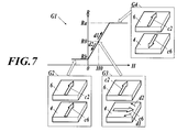
上記の「困難磁化軸の方向の制御磁場によって強制した中立位置」にある状態(図4)は、図7に示すTMR素子のH-R特性曲線G1上の点(H0,R0)にある状態に相当する。H0は磁場発生コイルa61よって発生した磁場である。
検出対象となる外部磁場が検出軸c7(図4)について変動すると、図7のG3において円弧矢印d1、d2で示すように自由層4の磁化の向きc6が振れる。円弧矢印d1方向に自由層4の磁化の向きc6が振れることは、図7に示すTMR素子のH-R特性曲線G1上で、直線矢印d1で示すように点(H0,R0)からスロープを上がることに相当し、大きく振れれば挿入図G3に示す状態から挿入図G4に示す状態に近づくことに相当する。反対に、円弧矢印d2方向に自由層4の磁化の向きc6が振れることは、図7に示すTMR素子のH-R特性曲線G1上で、直線矢印d2で示すように点(H0,R0)からスロープを下ることに相当し、大きく振れれば挿入図G3に示す状態から挿入図G2に示す状態に近づくことに相当する。
検出対象となる外部磁場が検出軸c7(図4)について変動すると、図7のG3において円弧矢印d1、d2で示すように自由層4の磁化の向きc6が振れる。円弧矢印d1方向に自由層4の磁化の向きc6が振れることは、図7に示すTMR素子のH-R特性曲線G1上で、直線矢印d1で示すように点(H0,R0)からスロープを上がることに相当し、大きく振れれば挿入図G3に示す状態から挿入図G4に示す状態に近づくことに相当する。反対に、円弧矢印d2方向に自由層4の磁化の向きc6が振れることは、図7に示すTMR素子のH-R特性曲線G1上で、直線矢印d2で示すように点(H0,R0)からスロープを下ることに相当し、大きく振れれば挿入図G3に示す状態から挿入図G2に示す状態に近づくことに相当する。
上記の「容易磁化軸の方向の制御磁場によって強制した中立位置」にある状態(図5)は、図8に示すTMR素子のH-R特性曲線G1上の点(H0,R0)にある状態に相当する。H0は磁場発生コイルa61よって発生した磁場である。
検出対象となる外部磁場が検出軸c7(図5)について変動すると、図8のG3において円弧矢印d1、d2で示すように自由層4の磁化の向きc6が振れる。円弧矢印d1方向に自由層4の磁化の向きc6が振れることは、図8に示すTMR素子のH-R特性曲線G1上で、直線矢印d1で示すように点(H0,R0)からスロープを上がることに相当し、大きく振れれば挿入図G3に示す状態から挿入図G4に示す状態に近づくことに相当する。反対に、円弧矢印d2方向に自由層4の磁化の向きc6が振れることは、図8に示すTMR素子のH-R特性曲線G1上で、直線矢印d2で示すように点(H0,R0)からスロープを下ることに相当し、大きく振れれば挿入図G3に示す状態から挿入図G2に示す状態に近づくことに相当する。
検出対象となる外部磁場が検出軸c7(図5)について変動すると、図8のG3において円弧矢印d1、d2で示すように自由層4の磁化の向きc6が振れる。円弧矢印d1方向に自由層4の磁化の向きc6が振れることは、図8に示すTMR素子のH-R特性曲線G1上で、直線矢印d1で示すように点(H0,R0)からスロープを上がることに相当し、大きく振れれば挿入図G3に示す状態から挿入図G4に示す状態に近づくことに相当する。反対に、円弧矢印d2方向に自由層4の磁化の向きc6が振れることは、図8に示すTMR素子のH-R特性曲線G1上で、直線矢印d2で示すように点(H0,R0)からスロープを下ることに相当し、大きく振れれば挿入図G3に示す状態から挿入図G2に示す状態に近づくことに相当する。
なお、図7及び図8で、縦軸RはTMR素子の抵抗を、横軸HはTMR素子に作用する外部磁場を示す。挿入図G2では磁化の向きC2,C6が平行状態、挿入図G4では磁化の向きC2,C6が反平行状態、挿入図G3では磁化の向きC2,C6が中立位置までねじれた状態を示す。磁化の向きC2,C6が平行状態では抵抗Rは下限Rbとなり、磁化の向きC2,C6が反平行状態では抵抗Rは上限Raとなる。
以上説明したTMR素子のH-R特性を利用して本磁気センサー10A、10Bは、脳磁気などの生体磁気信号や、非破壊検査装置において検査対象物に印加され当該検査対象物から漏れてくる所定周波のパルス波形などを形成する磁気信号を測定することができる。
一方、温度変化等の外乱により緩やかに変化する磁場変動についてはこれを検出しないように除去する。
測定対象とする頭蓋などの生体外面や、配管、壁などの非破壊検査装置における検査対象物の外面に、本磁気センサー10A、10Bを多数配置して、各センサーの検出値をマッピングできるように測定システムを構成して実施する。
一方、温度変化等の外乱により緩やかに変化する磁場変動についてはこれを検出しないように除去する。
測定対象とする頭蓋などの生体外面や、配管、壁などの非破壊検査装置における検査対象物の外面に、本磁気センサー10A、10Bを多数配置して、各センサーの検出値をマッピングできるように測定システムを構成して実施する。
図2に示した磁気センサー10Aにあっては、温度変化等の外乱により緩やかに変化する磁場変動については、点(H0,R0)で示す中立位置から矢印d1,d2に示すように磁化の向きC2とC6とのねじれ角、従ってTMR素子抵抗が変化しようとしても、ローパスフィルターa3を通過する信号となるので、上述したフィードバック制御により、点(H0,R0)で示す中立位置に安定化させる。
ローパスフィルターa3を通過しない比較的高周波の磁気変動については、磁場発生コイルa6までフィードバクされないので、磁化の向きC2とC6とのねじれ角、従ってTMR素子抵抗の変化を許し、その変化に応じた信号が計装増幅器a1、電圧増幅器a2、バッファー回路a7を介して、検出磁気信号として出力される。
ローパスフィルターa3のカットオフ周波数の設定により、温度変化等の外乱を除外し測定対象とする磁気信号を検出することができる。
以上のように、磁気センサー10Aのフィードバック回路は、検出磁気信号の変動周波数域外での外乱によって磁化の向きC2とC6とのねじれ角が影響を受けないように安定化させる。そして、磁気センサー10Aは、検出磁気信号の変動周波数域での当該ねじれ角の変動に応じた信号を、検出磁気信号として出力する。
図3に示した磁気センサー10Bにあっては、TMRモジュール1から比較器a4までの間にフィルターを設けていないので、検出磁気信号の変動周波数域を含めて外乱によって磁化の向きC2とC6とのねじれ角が影響を受けないように上述したフィードバック制御により、点(H0,R0)で示す中立位置に安定化する。
さらに磁気センサー10Bは、磁場発生コイルa6を制御する制御信号から比較的高周波の信号成分をハイパスフィルターb1で通過させ、バッファー回路b2を介して検出磁気信号として出力する。
ハイパスフィルターb1のカットオフ周波数の設定により、温度変化等の外乱による信号成分を除外し測定対象とする磁気信号を検出することができる。
以上のように、磁気センサー10Bのフィードバック回路は、検出磁気信号の変動周波数域を含めて外乱によって磁化の向きC2とC6とのねじれ角が影響を受けないように安定化させる。そして、磁気センサー10Bは、磁場発生源を制御する制御信号から検出磁気信号の変動周波数域にある信号を抽出して検出磁気信号として出力する。
以上説明したように本実施形態の磁気センサーによれば、図7又は図8に示したTMR素子のH-R特性のうち、点(H0,R0)を含んだ直線的な変化特性を示す領域を利用して磁気を計測でき、高感度化が達成され、微弱な磁気変化を高精度に計測することができる。直線的な変化特性を示す領域を利用するために、上記の中立位置における自由層の磁化の向きの固定層の容易磁化軸に対する所定のねじれ角を、45度から135度の間とすることが好ましい。より好ましくは、60度から120度である。
特に、図5に示すように自由層4の容易磁化軸c4の方向に磁場発生源からの磁場を作用させて自由層4の磁化の向きを所定のねじれ角を有したねじれの位置に安定化させて中立位置にする場合には、図8に示すようにTMR素子の磁場に対する抵抗変化が顕著となり、顕著に高感度化することができる。すなわち、図8に示すようなヒステリシスの高いH-R特性においては自由層の磁化の向きの変化、従って抵抗変化は非常に急激であり、制御磁場H0を与えることにより、検出磁場ゼロ(計測上のゼロ点)を図8のG3に示すねじり状態であって図8のG1に示す急勾配上の点(H0,R0)に持っていくことができ、極微小な検出磁場の変化に伴ってより急峻に磁化反転、従って抵抗を変化させることができるから、顕著に高感度化することができる。
なお、図9に示したH-R特性を利用した測定や、図7に示した点(H0,R0)及びその付近のH-R特性を利用した測定は、磁場のダイナミックレンジを要するような非破壊検査などに、図8に示した点(H0,R0)及びその付近のH-R特性を利用した測定は、脳磁場のような超微弱磁場の検出に向いている。
図2に示した磁気センサー10Aを、図4に示した「困難磁化軸の方向の制御磁場によって強制した中立位置」にある状態を形成するように構成して図7に示した点(H0,R0)及びその付近のH-R特性を利用して測定するようにしてもよいし、図5に示した「容易磁化軸の方向の制御磁場によって強制した中立位置」にある状態を形成するように構成して図8に示した点(H0,R0)及びその付近のH-R特性を利用して測定するようにしてもよい。
また、図3に示した磁気センサー10Bを、図4に示した「困難磁化軸の方向の制御磁場によって強制した中立位置」にある状態を形成するように構成して図7に示した点(H0,R0)及びその付近のH-R特性を利用して測定するようにしてもよいし、図5に示した「容易磁化軸の方向の制御磁場によって強制した中立位置」にある状態を形成するように構成して図8に示した点(H0,R0)及びその付近のH-R特性を利用して測定するようにしてもよい。
また、図3に示した磁気センサー10Bを、図4に示した「困難磁化軸の方向の制御磁場によって強制した中立位置」にある状態を形成するように構成して図7に示した点(H0,R0)及びその付近のH-R特性を利用して測定するようにしてもよいし、図5に示した「容易磁化軸の方向の制御磁場によって強制した中立位置」にある状態を形成するように構成して図8に示した点(H0,R0)及びその付近のH-R特性を利用して測定するようにしてもよい。
本発明は、微弱な磁気変化を高精度に計測することに利用することができる。
1 TMRモジュール
2 シリコン基板
3 下地層
4 強磁性金属磁化自由層
5 絶縁層
6 強磁性金属磁化固定層
7 ピンド層
8 バッファー層
9 上部電極層
10A 磁気センター
10B 磁気センター
41 軟磁性層
42 バリア層
43 強磁性層
61 強磁性層
62 バリア層
63 強磁性層
a6 磁場発生コイル
c1 容易磁化軸
c3 制御磁場
c4 容易磁化軸
c7 検出軸
R1 定抵抗
R2 定抵抗
R3 定抵抗
2 シリコン基板
3 下地層
4 強磁性金属磁化自由層
5 絶縁層
6 強磁性金属磁化固定層
7 ピンド層
8 バッファー層
9 上部電極層
10A 磁気センター
10B 磁気センター
41 軟磁性層
42 バリア層
43 強磁性層
61 強磁性層
62 バリア層
63 強磁性層
a6 磁場発生コイル
c1 容易磁化軸
c3 制御磁場
c4 容易磁化軸
c7 検出軸
R1 定抵抗
R2 定抵抗
R3 定抵抗
Claims (8)
- 磁化の向きが固定された強磁性金属磁化固定層、外部からの磁場の影響を受けて磁化の向きが変化する強磁性金属磁化自由層、及び、前記強磁性金属磁化固定層と前記強磁性金属磁化自由層との間に配置された絶縁層を有し、前記強磁性金属磁化固定層の磁化の向きと前記強磁性金属磁化自由層の磁化の向きとの角度差に従ってトンネル効果により前記絶縁層の抵抗を変化させるトンネル磁気抵抗素子を含む磁気センサーにおいて、
前記強磁性金属磁化自由層の磁化の向きに変化を与える磁場発生源を制御して、前記強磁性金属磁化自由層の磁化の向きを、前記強磁性金属磁化自由層の容易磁化軸から回転させて、前記強磁性金属磁化固定層の容易磁化軸に対して所定のねじれ角を有したねじれの位置に安定化させるフィードバック回路を備え、
変動する検出磁気信号を、前記フィードバック回路から出力することを特徴とする磁気センサー。 - 前記フィードバック回路は、前記検出磁気信号の変動周波数域外での外乱によって前記ねじれ角が影響を受けないように安定化させ、
前記検出磁気信号の変動周波数域での前記ねじれ角の変動に応じた信号を、前記検出磁気信号として出力することを特徴とする請求項1に記載の磁気センサー。 - 前記フィードバック回路は、前記検出磁気信号の変動周波数域を含めて外乱によって前記ねじれ角が影響を受けないように安定化させ、
前記磁場発生源を制御する制御信号から前記検出磁気信号の変動周波数域にある信号を抽出して前記検出磁気信号として出力することを特徴とする請求項1に記載の磁気センサー。 - 前記強磁性金属磁化自由層の容易磁化軸が前記強磁性金属磁化固定層の容易磁化軸に対し平行の関係にあることを特徴とする請求項1から請求項3のうちいずれか一に記載の磁気センサー。
- 前記フィードバック回路は、前記強磁性金属磁化自由層の困難磁化軸の方向に前記磁場発生源からの磁場を作用させて前記強磁性金属磁化自由層の磁化の向きを前記所定のねじれ角を有したねじれの位置に安定化させることを特徴とする請求項4に記載の磁気センサー。
- 前記フィードバック回路は、前記強磁性金属磁化自由層の容易磁化軸の方向に前記磁場発生源からの磁場を作用させて前記強磁性金属磁化自由層の磁化の向きを前記所定のねじれ角を有したねじれの位置に安定化させることを特徴とする請求項4に記載の磁気センサー。
- 前記所定のねじれ角を、45度から135度の間とすることを特徴とする請求項1から請求項6のうちいずれか一に記載の磁気センサー。
- 前記絶縁層がMgOからなることを特徴とするより請求項1から請求項7のうちいずれか一に記載の磁気センサー。
Applications Claiming Priority (2)
| Application Number | Priority Date | Filing Date | Title |
|---|---|---|---|
| JP2014-047740 | 2014-03-11 | ||
| JP2014047740A JP2017083173A (ja) | 2014-03-11 | 2014-03-11 | 磁気センサー |
Publications (1)
| Publication Number | Publication Date |
|---|---|
| WO2015137277A1 true WO2015137277A1 (ja) | 2015-09-17 |
Family
ID=54071721
Family Applications (1)
| Application Number | Title | Priority Date | Filing Date |
|---|---|---|---|
| PCT/JP2015/056826 Ceased WO2015137277A1 (ja) | 2014-03-11 | 2015-03-09 | 磁気センサー |
Country Status (2)
| Country | Link |
|---|---|
| JP (1) | JP2017083173A (ja) |
| WO (1) | WO2015137277A1 (ja) |
Cited By (2)
| Publication number | Priority date | Publication date | Assignee | Title |
|---|---|---|---|---|
| CN105486943A (zh) * | 2015-11-19 | 2016-04-13 | 江西洪都航空工业集团有限责任公司 | 一种复杂环境下电子部件干扰磁场的测量方法 |
| CN108780130A (zh) * | 2016-03-23 | 2018-11-09 | Tdk株式会社 | 磁传感器 |
Families Citing this family (3)
| Publication number | Priority date | Publication date | Assignee | Title |
|---|---|---|---|---|
| JP2019132719A (ja) * | 2018-01-31 | 2019-08-08 | 旭化成エレクトロニクス株式会社 | 磁気検出装置 |
| JP7082590B2 (ja) * | 2018-07-02 | 2022-06-08 | 旭化成エレクトロニクス株式会社 | 磁場測定装置、磁場測定方法、および磁場測定プログラム |
| US10983179B2 (en) | 2018-07-02 | 2021-04-20 | Asahi Kasei Microdevices Corporation | Magnetic field measuring device, magnetic field measurement method, and recording medium having recorded thereon magnetic field measurement program |
Citations (5)
| Publication number | Priority date | Publication date | Assignee | Title |
|---|---|---|---|---|
| JPH11316919A (ja) * | 1998-04-30 | 1999-11-16 | Hitachi Ltd | スピントンネル磁気抵抗効果型磁気ヘッド |
| JP2006296829A (ja) * | 2005-04-22 | 2006-11-02 | Meisei Electric Co Ltd | 生体磁気計測装置用の磁力計 |
| JP2013105825A (ja) * | 2011-11-11 | 2013-05-30 | Konica Minolta Advanced Layers Inc | 生体磁気センサー及びその製造方法 |
| JP2013137301A (ja) * | 2011-11-04 | 2013-07-11 | Honeywell Internatl Inc | 弱い磁場を検出するための2次調和検出モードの磁気抵抗センサを使用する方法 |
| JP2013238580A (ja) * | 2011-12-28 | 2013-11-28 | Tdk Corp | 電流センサ |
-
2014
- 2014-03-11 JP JP2014047740A patent/JP2017083173A/ja active Pending
-
2015
- 2015-03-09 WO PCT/JP2015/056826 patent/WO2015137277A1/ja not_active Ceased
Patent Citations (5)
| Publication number | Priority date | Publication date | Assignee | Title |
|---|---|---|---|---|
| JPH11316919A (ja) * | 1998-04-30 | 1999-11-16 | Hitachi Ltd | スピントンネル磁気抵抗効果型磁気ヘッド |
| JP2006296829A (ja) * | 2005-04-22 | 2006-11-02 | Meisei Electric Co Ltd | 生体磁気計測装置用の磁力計 |
| JP2013137301A (ja) * | 2011-11-04 | 2013-07-11 | Honeywell Internatl Inc | 弱い磁場を検出するための2次調和検出モードの磁気抵抗センサを使用する方法 |
| JP2013105825A (ja) * | 2011-11-11 | 2013-05-30 | Konica Minolta Advanced Layers Inc | 生体磁気センサー及びその製造方法 |
| JP2013238580A (ja) * | 2011-12-28 | 2013-11-28 | Tdk Corp | 電流センサ |
Cited By (2)
| Publication number | Priority date | Publication date | Assignee | Title |
|---|---|---|---|---|
| CN105486943A (zh) * | 2015-11-19 | 2016-04-13 | 江西洪都航空工业集团有限责任公司 | 一种复杂环境下电子部件干扰磁场的测量方法 |
| CN108780130A (zh) * | 2016-03-23 | 2018-11-09 | Tdk株式会社 | 磁传感器 |
Also Published As
| Publication number | Publication date |
|---|---|
| JP2017083173A (ja) | 2017-05-18 |
Similar Documents
| Publication | Publication Date | Title |
|---|---|---|
| US11733317B2 (en) | Bipolar chopping for 1/f noise and offset reduction in magnetic field sensors | |
| CN105093138B (zh) | 磁场检测传感器及使用其的磁场检测装置 | |
| JP4807535B2 (ja) | 磁気センサ | |
| JP4722934B2 (ja) | 所定の温度係数を有する抵抗器 | |
| CN104076302B (zh) | 三轴磁场传感器、制作磁场感测结构的方法与感测电路 | |
| CN107076784B (zh) | 电流传感器 | |
| WO2015146656A1 (ja) | 磁気センサー | |
| WO2015137277A1 (ja) | 磁気センサー | |
| JP2011027683A (ja) | 磁気センサ | |
| US20130082698A1 (en) | Current sensor | |
| JP6845247B2 (ja) | スピンホール現象を利用した磁界測定装置および方法 | |
| JP6299069B2 (ja) | 磁気センサ装置 | |
| CN106645797A (zh) | 一种基于间隙改变的隧道磁阻效应加速度计装置 | |
| JP2016130686A (ja) | 磁気センサ | |
| JP2018146314A (ja) | 磁気センサ、磁気センサ装置 | |
| JP2015219227A (ja) | 磁気センサ | |
| JP2019132719A (ja) | 磁気検出装置 | |
| JP6460372B2 (ja) | 磁気センサ及びその製造方法、並びにそれを用いた計測機器 | |
| US11009569B2 (en) | Magnetic field sensing device | |
| JP2012063203A (ja) | 磁気センサ | |
| JP6969751B2 (ja) | トンネル磁気抵抗素子及び磁化方向補正回路 | |
| US20200333408A1 (en) | Magnetoresistive Magnetic Field Sensor Bridge with Compensated Cross-Axis Effect | |
| CN215639260U (zh) | 一种磁阻电路结构及角度传感器 | |
| JP2022538754A (ja) | 磁気抵抗差動フルブリッジを備える磁気電流磁場センサ | |
| TWI479171B (zh) | 磁場感測裝置及方法 |
Legal Events
| Date | Code | Title | Description |
|---|---|---|---|
| 121 | Ep: the epo has been informed by wipo that ep was designated in this application |
Ref document number: 15761551 Country of ref document: EP Kind code of ref document: A1 |
|
| NENP | Non-entry into the national phase |
Ref country code: DE |
|
| 122 | Ep: pct application non-entry in european phase |
Ref document number: 15761551 Country of ref document: EP Kind code of ref document: A1 |
|
| NENP | Non-entry into the national phase |
Ref country code: JP |