WO2015137341A1 - Dispositif de projection de lumière et procédé de projection de lumière - Google Patents
Dispositif de projection de lumière et procédé de projection de lumière Download PDFInfo
- Publication number
- WO2015137341A1 WO2015137341A1 PCT/JP2015/057018 JP2015057018W WO2015137341A1 WO 2015137341 A1 WO2015137341 A1 WO 2015137341A1 JP 2015057018 W JP2015057018 W JP 2015057018W WO 2015137341 A1 WO2015137341 A1 WO 2015137341A1
- Authority
- WO
- WIPO (PCT)
- Prior art keywords
- light projecting
- light
- unit
- projection
- shape
- Prior art date
- Legal status (The legal status is an assumption and is not a legal conclusion. Google has not performed a legal analysis and makes no representation as to the accuracy of the status listed.)
- Ceased
Links
Images


Classifications
-
- G—PHYSICS
- G03—PHOTOGRAPHY; CINEMATOGRAPHY; ANALOGOUS TECHNIQUES USING WAVES OTHER THAN OPTICAL WAVES; ELECTROGRAPHY; HOLOGRAPHY
- G03B—APPARATUS OR ARRANGEMENTS FOR TAKING PHOTOGRAPHS OR FOR PROJECTING OR VIEWING THEM; APPARATUS OR ARRANGEMENTS EMPLOYING ANALOGOUS TECHNIQUES USING WAVES OTHER THAN OPTICAL WAVES; ACCESSORIES THEREFOR
- G03B21/00—Projectors or projection-type viewers; Accessories therefor
- G03B21/14—Details
- G03B21/147—Optical correction of image distortions, e.g. keystone
-
- G—PHYSICS
- G03—PHOTOGRAPHY; CINEMATOGRAPHY; ANALOGOUS TECHNIQUES USING WAVES OTHER THAN OPTICAL WAVES; ELECTROGRAPHY; HOLOGRAPHY
- G03B—APPARATUS OR ARRANGEMENTS FOR TAKING PHOTOGRAPHS OR FOR PROJECTING OR VIEWING THEM; APPARATUS OR ARRANGEMENTS EMPLOYING ANALOGOUS TECHNIQUES USING WAVES OTHER THAN OPTICAL WAVES; ACCESSORIES THEREFOR
- G03B17/00—Details of cameras or camera bodies; Accessories therefor
- G03B17/48—Details of cameras or camera bodies; Accessories therefor adapted for combination with other photographic or optical apparatus
- G03B17/54—Details of cameras or camera bodies; Accessories therefor adapted for combination with other photographic or optical apparatus with projector
-
- G—PHYSICS
- G03—PHOTOGRAPHY; CINEMATOGRAPHY; ANALOGOUS TECHNIQUES USING WAVES OTHER THAN OPTICAL WAVES; ELECTROGRAPHY; HOLOGRAPHY
- G03B—APPARATUS OR ARRANGEMENTS FOR TAKING PHOTOGRAPHS OR FOR PROJECTING OR VIEWING THEM; APPARATUS OR ARRANGEMENTS EMPLOYING ANALOGOUS TECHNIQUES USING WAVES OTHER THAN OPTICAL WAVES; ACCESSORIES THEREFOR
- G03B21/00—Projectors or projection-type viewers; Accessories therefor
- G03B21/54—Accessories
-
- H—ELECTRICITY
- H04—ELECTRIC COMMUNICATION TECHNIQUE
- H04N—PICTORIAL COMMUNICATION, e.g. TELEVISION
- H04N9/00—Details of colour television systems
- H04N9/12—Picture reproducers
- H04N9/31—Projection devices for colour picture display, e.g. using electronic spatial light modulators [ESLM]
- H04N9/3179—Video signal processing therefor
- H04N9/3185—Geometric adjustment, e.g. keystone or convergence
Definitions
- the present invention relates to a light projecting device that projects light of a predetermined shape onto the surface of an object.
- Projection mapping is a video technique that synchronizes the real and the video, so there is an attractive world view created by the fusion of the real and the video.
- a projected image is projected according to the surface shape of the three-dimensional object that is the projection target so that when the image is projected, the projected image is exactly superimposed on the three-dimensional object that is the projection target Is changed.
- Fantastic and illusion that makes the viewer feel as if the three-dimensional object moves, deforms, or emits light by moving or changing the image that overlaps the three-dimensional object that is the projection target.
- Realistic images are expressed.
- Patent Document 1 requires that the optical axes of the camera and the projector coincide with each other. Further, the technique disclosed in Patent Document 1 cannot control the light projecting direction of the projector when the moving speed of the projection target is fast and is not captured in the captured image of the camera.
- the projected image needs to be changed according to the surface shape of the projection object. If this process takes time, the image will not catch up with the movement of the object. May not be mapped to the object.
- the present invention is an invention made in view of the above-described circumstances, and the present invention provides a light projecting apparatus and a method capable of projecting light (video) having a predetermined shape onto a moving object. For the purpose.
- the light projecting device includes a light projecting optical system that projects light, a light projecting unit that projects light of a predetermined shape onto the light projecting object, and a three-dimensional position of the light projecting object.
- a position detecting unit to detect, a light projecting direction changing unit for changing the light projecting direction of the light projecting unit, and a position detected by the position detecting unit by causing the light projecting direction changing unit to change the light projecting direction.
- a projection direction control unit that projects light onto the projection target object, a shape calculation unit that calculates the shape of light projected onto the surface of the projection target object at the position detected by the position detection unit, A shape control unit that causes the light projecting unit to project light having the shape calculated by the shape calculating unit. Therefore, when the light projecting object moves, it is possible to quickly project the light projecting object.
- FIG. 1 It is a figure which shows the example of the functional block of the light projection apparatus by embodiment of this invention. It is a figure for demonstrating the external appearance of the light projector shown in FIG. 1, and a light projection part. It is a figure which shows an example (shift of a lens group) of the light projection part of the light projector shown in FIG. It is a figure which shows an example (rotation of a mirror) of the light projection part of the light projector shown in FIG. It is a figure which shows an example of the light projection direction change part of the light projection apparatus shown in FIG. It is a figure for demonstrating the conventional tracking method. It is a time chart of the light projection process of the conventional tracking method. It is a figure for demonstrating the asynchronous method of the light projection apparatus shown in FIG.
- FIG. 1 is a diagram illustrating an example of functional blocks of a light projecting device 100 according to an embodiment of the present invention.
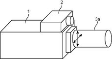
- 2 shows an external view of the light projecting device 100
- FIGS. 3 and 4 show an example of a light projecting unit 3 to be described later
- FIG. 5 shows an example of a light projecting direction changing unit 4.
- the light projecting device 100 includes a light projecting main body unit 1, a position detecting unit 2, a light projecting unit 3, a light projecting direction changing unit 4, and an interface unit 5.
- the light projecting device 100 is a device that acquires a video from the external video content storage unit 6 and projects a video based on the acquired video to the projection target object Ob.
- the light projecting body unit 1 performs overall control of the light projecting device 100, and includes a video content acquisition unit 11, an image processing unit 12 (shape calculation unit), a video display control unit 13 (shape control unit), and a light projection direction.
- a control unit 14 is provided.
- the video content acquisition unit 11 acquires video from the video content storage unit 6.
- the video content storage unit 6 is a portable recording medium such as a USB (Universal Serial Bus) memory, for example, and the video content acquisition unit 11 includes a connection unit corresponding to the recording medium and implements a read / write function. It is.
- USB Universal Serial Bus
- the image processing unit 12 generates a video that has been changed according to an instruction from the video display control unit 13 from the video acquired by the video content acquisition unit 11. For example, the image processing unit 12 changes the shape of the image in accordance with a change (for example, rotation) of the shape of the projection object Ob, or changes the size of the image according to the distance to the projection object Ob. Or perform necessary calculation processing such as keystone correction and luminance correction.
- the image processing unit 12 includes a shape deformation processing unit 121.
- the shape transformation processing unit 121 performs a part of the image processing performed by the image processing unit 12, for example, a process of changing the shape of the video in accordance with the appearance of the projected object Ob.
- the shape deformation processing unit 121 is configured to deform the shape of the video as a part of the image processing. In the case of changing, for example, a rough shape change such as no rotation may be performed as part of the processing.
- the video display control unit 13 instructs the image processing unit 12 to perform image processing according to the position coordinates (x, y, z) of the projection object Ob detected by the position detection unit 2, and image processing by the image processing unit 12 is performed.
- the subsequent image is projected to the light projecting unit 3.
- the video display control unit 13 includes a transmissive liquid crystal panel and a light source, displays video on the liquid crystal panel, transmits irradiation light from the light source, and outputs the transmitted light to the light projecting unit 3.
- the video display control unit 13 notifies the projection direction control unit 14 of the end of the image processing by the video display control unit 13 when the synchronization processing is instructed by the user via the interface unit 5.
- the synchronization process is described in the section ⁇ Follow-up process>.
- the light projecting direction control unit 14 instructs the light projecting direction changing unit 4 to direct the light projecting direction of the light projecting unit 3 to the position of the light projecting object Ob detected by the position detecting unit 2.
- the position detection unit 2 repeatedly detects the position coordinates (for example, coordinates in the world coordinate system) of the projection object Ob at a predetermined cycle, and outputs the position coordinates to the video display control unit 13 and the projection direction control unit 14.
- the position detection unit 2 is, for example, an IR (infrared) camera, and includes a light source and an image sensor.
- the position detection unit 2 measures the time until the irradiation light from the light source is reflected by the projection object Ob and returns. A distance image of the light object Ob is created.
- the position detection unit 2 is not limited to the IR camera, and may be a stereo camera, for example, and may detect the position coordinates of the projection object Ob by a distance measuring method using parallax of a stereo image.
- the IR camera (position detecting unit 2) is installed on the upper surface of the projector main body (projecting main body unit 1). It may be built in or may be installed at a location away from the projector body.
- the IR camera (position detection unit 2) may be installed in a place where the position of the projection object Ob can be detected.
- the IR camera (position detecting unit 2) and the projector main body (light projecting main unit 1) have a function of transmitting and receiving position coordinates detected by the position detecting unit 2.
- the position detection unit 2 by mounting the position detection unit 2 on the light projecting device 100, the operability such as carrying is improved, and the light projection directions of the position detection unit 2 and the light projection unit 3 are matched, that is, the position detection unit. 2 can be directed toward the light projecting object Ob.
- the light projecting unit 3 has a light projecting optical system 31 and projects the video input from the video display control unit 13 onto the light projecting object Ob.
- the light projecting optical system 31 includes one or a plurality of lens groups that are one or a plurality of optical lenses along the optical axis, and may further include a mirror or the like as necessary.
- the light projecting direction changing unit 4 changes (corrects) the light projecting direction of the light projecting unit 3 in accordance with an instruction from the light projecting direction control unit 14.
- the light projection direction is changed by the following four methods.
- the lens barrel 3a itself, which is an example of the light projecting unit 3, has two horizontal directions or vertical directions in the direction of the arrows (perpendicular to the optical axis of the light projecting unit 3 and perpendicular to each other.
- the projection direction is changed by shifting to (direction).
- the light projecting direction changing unit 4 in this case is a drive device such as an actuator using a piezoelectric element or an actuator using a voice coil for shifting the lens barrel.
- the shift direction of the lens barrel 3a is not limited to the arrow direction, and may be a direction orthogonal to the optical axis of the light projecting unit 3.
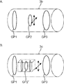
- the lens group (projecting optical system 31) in the lens barrel (projecting unit 3) is perpendicular to the optical axis of the projecting optical system 31 and is mutually orthogonal.
- the light projection direction is changed by shifting in two orthogonal directions (horizontal direction or vertical direction).
- the lens barrel 3b of FIG. 3A includes three lens groups GP1, GP2, and GP3 each including one optical lens as the light projecting optical system 31, and the lens group GP2 is shifted as necessary.
- the 3B includes lens groups GP1 and G3 among the three lens groups, each including one optical lens, the lens group GP2 ′ including a plurality of optical lenses, and the lens group GP2 ′ including the lens group GP2 ′. Shifted by group.
- the light projecting direction changing unit 4 in this case is a driving device for shifting the lens group.
- the shift direction of the lens groups GP2 and GP2 ′ is not limited to the arrow direction, and may be a direction orthogonal to the optical axis of the light projecting optical system 31.
- FIG. 4A is a front view of the lens barrel 3d including the mirror M1 and the mirror M2 as the light projecting optical system 31 as viewed from the light projecting object Ob side.
- FIG. 4B is a perspective view of the lens barrel 3d.
- the lens barrel 3d is formed by connecting three cylindrical portions, a first cylindrical portion, a second cylindrical portion, and a third cylindrical portion.
- the other end of the first cylindrical portion and the one end of the second cylindrical portion are connected by the first connecting portion so that the central axes of the respective cylindrical portions are orthogonal to each other.
- the other end of the second cylindrical portion and the one end of the third cylindrical portion are perpendicular to the central axis of each cylindrical portion, and the central axis of the third cylindrical portion is the central axis of the first cylindrical portion and the second cylinder. They are connected by the second connecting part so as to coincide with the normal line of the plane constituted by the central axis of the part.
- the first connecting portion is provided with a mirror M1 having a rotation axis AX1 in a direction coinciding with a normal line of a plane formed by the central axis of the first cylindrical portion and the central axis of the second cylindrical portion, and the second connecting portion.
- a mirror M2 having a rotation axis AX2 in a direction coinciding with a normal line of a plane constituted by the central axis of the second cylindrical part and the central axis of the third cylindrical part is installed in the part.
- the light beam L is incident from one end of the first cylindrical portion, is reflected by the mirror M1, is incident on the mirror M2, is reflected by the mirror 2, and is emitted from the other end of the third cylindrical portion.
- the light projecting direction changing unit 4 in this case is a drive device that rotates the mirror.
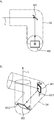
- the pan / tilt head includes a pan driving unit 41 and a tilt driving unit 42.
- the pan drive unit 41 rotates in the pan direction (see an arrow) about the pan rotation axis AX41.
- the tilt drive unit 42 rotates in the tilt direction (see an arrow) about the tilt rotation shaft 42 orthogonal to the pan rotation axis AX41.
- the light projecting direction changing unit 4 in this case is a pan / tilt head.
- the interface unit 5 includes an input unit that inputs an instruction from the user to the light projecting device 100, and an output unit that notifies the user of a message or the like from the light projecting device 100.
- the interface unit 5 is, for example, a touch panel.
- the input unit is a position input device that detects and inputs an operation position such as a resistance film method or a capacitance method
- the output unit is a display device.
- one or a plurality of input content candidates that can be input such as buttons are displayed on the display surface of the display device, and when the user touches a button that displays the input content that the user wants to input, the button displays the input content.
- the displayed contents are input to the light projecting device 100 as user operation input contents.
- the light projecting device 100 includes two methods as a light projecting method (hereinafter also referred to as “following method”) to the moving body, as described in the section ⁇ Following method>.
- following method a light projecting method to the moving body, as described in the section ⁇ Following method>.
- the user instructs the light projecting device 100 through the interface unit 5 which tracking method to use.
- the light projecting main unit 1 is constituted by, for example, a microcomputer including a microprocessor, a memory, and peripheral circuits thereof.
- the memory is used for controlling a program for performing image processing and the entire light projecting device 100.
- Various programs such as control programs and various data such as data necessary for program execution are stored, and a microprocessor such as a so-called CPU (Central Processing Unit) executes a program stored in the memory. All or part of each functional unit is realized.
- a microcomputer including a microprocessor, a memory, and peripheral circuits thereof.
- the memory is used for controlling a program for performing image processing and the entire light projecting device 100.
- Various programs such as control programs and various data such as data necessary for program execution are stored, and a microprocessor such as a so-called CPU (Central Processing Unit) executes a program stored in the memory. All or part of each functional unit is realized.
- CPU Central Processing Unit
- the light projecting device 100 can execute two following methods.
- the first method is a method of following the moving body by directing the light projecting direction of the light projecting unit 3 toward the light projecting object Ob every time the position detecting unit 2 detects the position of the light projecting object Ob. is there.
- the second method is to move the light projecting direction of the light projecting unit 3 toward the light projecting object Ob between the time when only the shape deformation process of the image process is completed and the time when the image process is completed. It is a method of following the body.
- the first method is referred to as “asynchronous method”
- the second method is referred to as “synchronous method”. Directing the light projecting direction of the light projecting unit 3 toward the light projecting object Ob is called “optical correction”.
- a conventional method that is, a case of following a moving object by performing image processing and changing an image without performing optical correction will be described with reference to FIGS.
- the case of following the moving object using the “method” will be described with reference to FIGS.
- the image projected on the projection object is created only by image processing.
- the position of the projection object is detected by a camera or the like, and image processing for correcting the projected image according to the detected position, for example, in the projected image
- a predetermined image is cut out, and an image to be projected is created by performing processing such as creating an image whose position is changed, and the created image is projected.
- the image processing time tends to become longer as the projected image becomes more complicated and as the surface shape of the projection object becomes more complicated. Therefore, when such image processing takes time, if the projection target is a moving object, the projected video is not projected onto the projection target, that is, the projected video is It may be removed from the projection object Ob.
- the delay time also occurs, so that there are more cases where the video is not projected onto the projection target. .
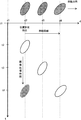
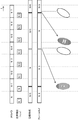
- FIG. 6 shows an example in which an image is projected onto a moving body by a conventional method.
- the horizontal axis indicates the position of the projection object, and the vertical axis indicates the time.
- the projection object is indicated by an ellipse, and the projected image is indicated by a lattice pattern without a frame.
- the result of the ideal project matching that is, an ellipse with a lattice pattern in which the image fits perfectly with the moving projection object is shown.
- FIG. 7 is a timing chart of the light projection processing by the conventional method.
- the uppermost “IR camera” indicates position detection processing by an IR (infrared) camera (distance image camera) of the position detection unit 2, and a rectangle indicates a distance image detection cycle.
- the second stage “position detection” indicates a process for calculating the position coordinates (x, y, z) of the projection object from the distance image detected by the IR camera, and the rectangle indicates the calculation time.
- “N”, “N + 1”, etc. in the rectangle indicate identifiers of the positions of the projection objects Ob detected by the IR camera (hereinafter referred to as “positions“ N ””, etc.).
- the third level “image formation” indicates image processing performed by the image processing unit 12 according to the position coordinates of the projection object, and the rectangle indicates the processing time. “N” or the like in the rectangle indicates image processing according to the position “N” or the like.
- the fourth “frame Buf” indicates an image stored in the frame buffer. “N” or the like in the rectangle indicates that an image processed according to the position “N” is stored. Here, for convenience of explanation, it is assumed that there is one frame buffer.
- the bottom row shows the projected image and the projection object.
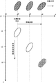
- FIG. 8 shows an example in which light is projected onto a moving body by the “asynchronous method” of the light projecting device 100.
- the position of the projection target at position d2 is detected at time t2.
- the image-processed video is projected onto the light projecting object moving to the position d4 at time t4.
- FIG. 9 is a timing chart of the light projection processing by the “asynchronous method” of the light projector 100.
- the first to fourth charts in FIG. 9 are the same as the first to fourth charts in FIG.
- the fifth stage “optical tracking” indicates the timing of optical correction.
- “N” or the like in the rectangle indicates the position of the projection object Ob detected by the IR camera, that is, the direction in which the projection direction of the projection unit 3 is changed.
- the bottom row shows the projected image and the projection object Ob.
- the ellipse at the bottom indicates the optically corrected projection object Ob, the lattice pattern without a frame indicates the projected image, and “N” and the like therein indicate the projection target at the position “N”.
- the video image-processed according to the object Ob is shown.
- the light projecting device 100 performs optical correction asynchronously with image processing. That is, the light projecting device 100 performs optical correction as soon as the position is detected by the IR camera (position detection unit 2) without waiting for the end of the image processing. Further, it is not affected by the delay time due to the frame buffer of the projector. Accordingly, it is possible to project an image on the projection object Ob that moves at high speed.
- the light projecting device 100 projects an image on the light projecting object Ob by optical correction before the image processing is completed, it cannot project a perfect image corresponding to the position of the light projecting object Ob.
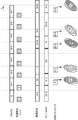
- FIG. 10 shows an example in which light is projected onto a moving body by the “synchronization method” of the light projecting device 100.
- the image processing when the time from the time t2 to the time t3 is required as the time for the shape deformation process, the image after the shape deformation process is projected onto the light projecting object moving to the position d3 at the time t3. .
- An image for which only shape processing has been completed is indicated by a dot pattern without a frame, and an image for which image processing has been completed is indicated by a lattice pattern without a frame.
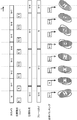
- FIG. 11 is a timing chart of the light projecting process by the “synchronization method” of the light projecting device 100.
- the first to fifth charts in FIG. 11 are the same as the first to fifth charts in FIG.
- “(N)” and the like indicate shape processing in the image processing at the position “N”, and “(N)” in the fourth-stage “frame Buf”. Etc. indicate that an image for which only shape processing has been completed is stored.
- the light projecting device 100 performs optical correction in synchronization with image processing. That is, the light projecting device 100 performs the optical correction so that the light projecting direction is directed to the position of the most recently detected light projecting object Ob at the time when the shape processing is completed in the image processing, and the image processing is completed. At the time, further, optical correction is performed so that the light projection direction is directed to the position of the light projection object Ob detected most recently. Since only the shape processing is completed in a relatively short time, when the moving speed of the projection object Ob is relatively low, the light projection device is obtained by synchronizing the optical correction and the shape processing. 100 can project an image that exactly matches the projection object Ob.
- a predetermined image projected on a moving object is cut out from one frame image, and the predetermined image is moved to the position detected by the position detection unit 2.
- the light projecting device 100 does not need to perform this process by performing optical correction.
- the predetermined image is moved within one frame image, the number of pixels of the predetermined image must be reduced.
- more pixels are allocated to the predetermined image.
- the resolution is improved, and the light projecting device 100 can project a clearer image.
- the light projecting device 100 performs the next image processing after the image processing including the shape processing is completed. It may be performed in parallel with image processing. For example, the light projecting device 100 performs the process “(N)” in parallel with the process “N-3”. Although resources and the like for performing parallel processing are required, image processing can be performed in a shorter time. Therefore, the light projecting device 100 projects an image on the light projecting object Ob that moves faster. Is possible.
- FIG. 12 is a flowchart of the light projection process.
- the flowchart on the left side of FIG. 12 is a process performed by the video display control unit 13, and the flowchart on the right side is a process performed by the light projection direction control unit 14.
- the video display control unit 13 and the light projecting direction control unit 14 operate independently without synchronizing, and perform tracking by the “synchronous method”. When performing, it operates in synchronization.
- the user operates the interface unit 5 to instruct a follow-up method of either “synchronization method” or “asynchronous method”. And a user inputs the command which instruct
- the light projecting main body unit 1 that has detected that a command for instructing the start of the light projection process is input via the interface unit 5 first reads the video content from the video content storage unit 6 to the video content acquisition unit 11. The start of operation is instructed to the position detection unit 2, the light projecting unit 3, and the light projecting direction changing unit 4. In addition, the light projecting main body unit 1 follows the user-instructed tracking method, that is, the “synchronizing method” or “asynchronous” to the image processing unit 12, the video display control unit 13, and the light projection direction control unit 14. One of "method” is notified.
- the video content acquisition unit 11 Upon receiving the instruction, the video content acquisition unit 11 reads the video data from the video content storage unit 6 and starts output to the image processing unit 12. In addition, the position detection unit 2 starts detecting the position of the projection object Ob, and periodically detects the position coordinates of the projection object Ob detected at a predetermined period, and the image display control unit 13 and the projection direction control. To the unit 14.
- the video display control unit 13 that has input the position coordinates of the projection object Ob from the position detection unit 2 (step S10) outputs the input position coordinates to the image processing unit 12.
- step S11: Yes the image processing unit 12 that has input the video data from the video content acquisition unit 11 has the latest projection object Ob input from the video display control unit 13. Image processing using the position coordinates is started.
- step S12: No the image processing unit 12 responds to the position coordinates of the light projecting object Ob with respect to the video data. Perform image processing. Then, the image processing unit 12 stores the image-processed video in the frame buffer (step S13).
- the video display control unit 13 reads the video from the frame buffer and displays it at a predetermined frame rate (step S16). In the flowchart of FIG. 12, for convenience of explanation, it is described that video is displayed in step S16. However, the video display control unit 13 always reads video from the frame buffer and displays it at a predetermined frame rate. It is assumed that
- step S12 when “synchronization method” is notified as the follow-up method from the light projecting main body unit 1 in step S12 (step S12: Yes), the image processing unit 12 performs the shape transformation process in the video data. And stored in the frame buffer (step S14). Then, the image processing unit 12 notifies the video display control unit 13 that the shape deformation process has been completed. Upon receiving the notification, the video display control unit 13 outputs a synchronization signal to the light projection direction control unit 14.
- the image processing unit 12 performs image processing other than the shape deformation processing on the video data and stores it in the frame buffer (step S15). Then, the image processing unit 12 notifies the video display control unit 13 that the shape deformation process has been completed. Upon receiving the notification, the video display control unit 13 outputs a synchronization signal to the light projection direction control unit 14.
- the video display control unit 13 reads the video from the frame buffer and displays it at a predetermined frame rate (step S16).
- the video display control unit 13 displays the video after the shape transformation process when the video subjected to the shape transformation process is stored in the frame buffer, and the video after the whole image processing is stored in the frame buffer. If so, display the video.
- the projection direction control unit 14 that has input the position coordinates of the projection object Ob from the position detection unit 2 (step S20) is notified of the “asynchronous method” as the follow-up method from the projection main unit 1 ( Step S21: No), in accordance with the light projection direction changing unit 4, the instruction data for directing the light projection direction of the light projecting unit 3 to the position coordinates of the light projection object Ob input from the position detection unit 2 is created. And output to the light projecting direction changing unit 4. For example, when the light projecting direction changing unit 4 is a pan / tilt head as shown in FIG. 5, pan angle information and tilt angle information are calculated and output to the light projecting direction changing unit 4.
- the light projecting direction changing unit 4 Upon receiving the instruction, the light projecting direction changing unit 4 operates based on the instruction data input from the light projecting direction control unit 14, and changes the light projecting direction of the light projecting unit 3 (step S23).
- step S21: Yes when “synchronization method” is notified as the follow-up method from the light projecting main body unit 1 in step S21 (step S21: Yes), the light projection direction control unit 14 receives the synchronization signal from the video display control unit 13. Is input (step S22: No), and when a synchronization signal is input (step S22: Yes), the light projecting unit is set to the position coordinates of the latest projecting object Ob input from the position detecting unit 2. 3 is generated in accordance with the light projecting direction changing unit 4 and is output to the light projecting direction changing unit 4. Upon receiving the instruction, the light projecting direction changing unit 4 operates based on the instruction data input from the light projecting direction control unit 14, and changes the light projecting direction of the light projecting unit 3 (step S23). However, if the latest position coordinates are not different from the previous position coordinates by a predetermined threshold value or less, the light projection direction is maintained.
- the light projecting device 100 performs the tracking process of the moving body by providing a function of changing the light projecting direction of the lens barrel (light projecting unit) 3.
- the lens barrel (light projecting unit) 3 is provided with not only a function of changing the light projecting direction but also a zoom function and a focus function.
- FIG. 13 shows an example when the light projecting object Ob approaches the light projecting device 100.
- the light projection object Ob (ellipse) becomes larger.
- the image (lattice pattern without a frame) is the size of the light projecting object Ob at the time t2, it is smaller than the light projecting object Ob and becomes a blurred image.
- FIG. 3 An example in which a zoom function and a focus function are added to the lens barrel (light projecting unit) 3 is shown in FIG.
- an image that matches the size of the projection object Ob is displayed for the projection object Ob that is apparently larger than that at time t2.
- the projection optical system 31 is changed to the wide angle side by the zoom function, and a large image is projected onto the projection object Ob.
- the focus function corrects a focus shift due to a change in the distance between the light projecting object Ob and the light projecting device 100.
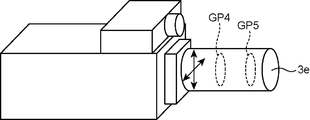
- FIG. 15 is a diagram illustrating an example of a lens barrel (light projecting unit) 3e according to the second embodiment.
- the lens barrel (light projecting unit) 3e has two groups of lens groups GP4 and GP5, and performs zooming by moving the lens groups GP4 and GP5, and changes the focal position.
- the light projecting direction control unit 14 instructs the light projecting direction changing unit 4 to change the angle of view and the focal length in addition to the change of the light projecting direction according to the distance to the light projecting object Ob. Then, the size of the image projected by the light projecting unit 3 is changed, and the focus is adjusted.
- the change in the size of the video accompanying the change in the distance between the light projecting object Ob and the light projecting device 100 can also be performed by image processing.
- the image processing unit 12 cuts out a predetermined image and converts it into a size corresponding to the apparent size of the projection object Ob.
- the light projection unit 3 is provided with a zoom function and optically zooms, the moving body can be moved at high speed. Since it is impossible to adjust the focal length by image processing, the focus function needs to be performed optically.
- the user selects to use the “synchronizing method” or “asynchronous method” as the follow-up method, and the user instructs the light projecting device 100 via the interface unit 5.
- the light projecting body unit 1 (switching unit) calculates the moving speed of the light projecting object Ob based on the position coordinates of the light projecting object Ob periodically detected by the position detecting unit 2, and the moving speed is predetermined.
- the “asynchronous method” may be used when the threshold is equal to or higher than the threshold, and the “synchronous method” may be used when the calculated moving speed is lower than the threshold.
- the predetermined threshold is determined from various conditions such as the detection period of the position detection unit 2 and the time required to change the light projection direction of the light projection unit 3.
- a light projecting device includes a light projecting optical system that projects light, a light projecting unit that projects light of a predetermined shape onto a light projecting object, and a three-dimensional position of the light projecting object.
- a position detecting unit to detect, a light projecting direction changing unit for changing the light projecting direction of the light projecting unit, and a position detected by the position detecting unit by causing the light projecting direction changing unit to change the light projecting direction.
- a projection direction control unit that projects light onto the projection target object, a shape calculation unit that calculates the shape of light projected onto the surface of the projection target object at the position detected by the position detection unit, A shape control unit that causes the light projecting unit to project light having the shape calculated by the shape calculating unit.
- a light projecting method includes a light projecting optical system that projects light, and a light projecting device that includes a light projecting unit that projects light of a predetermined shape onto a light projecting target.
- the method includes a position detecting step of detecting a three-dimensional position of the light projecting object, a light projecting direction changing step of changing the light projecting direction of the light projecting unit, and a light projecting direction changing step.
- a light projection direction control step of changing the light direction to project light onto the light projection object at the position detected in the position detection step, and a surface of the light projection object at the position detected in the position detection step A shape calculating step for calculating the shape of the light to be projected onto the light source, and a shape control step for causing the light projecting unit to project the light having the shape calculated in the shape calculating step.
- the light projecting device changes the light projecting direction of the light projecting unit and projects light onto the light projecting object. Therefore, when the light projecting object moves, the light projecting object quickly Can be projected.
- an asynchronous mode in which the light projecting direction control unit causes the light projecting direction changing unit to change the light projecting direction is asynchronous with the timing at which the shape control unit projects light onto the light projecting unit.
- the light projecting direction of the light projecting unit is changed without synchronizing with the timing of projecting the light projecting object, that is, without depending on the end of the video processing.
- the light projecting device can quickly project the light projecting object.
- the light projecting direction control unit causes the light projecting direction changing unit to change the light projecting direction in synchronization with the timing at which the shape control unit projects light onto the light projecting unit.
- a synchronization mode and when the shape control unit finishes a part of the process performed by the shape calculation unit, the shape control unit projects light from the part of the process to the light projecting unit, and performs all the processes. When the process is completed, the light from all the processes is projected onto the light projecting unit.
- the projection object moves at a low speed because it synchronizes with the timing of projecting the projection object, that is, the projection direction of the projection unit is changed according to the end of the video processing.
- the light projecting device can project the light obtained by part of the processing of the shape calculating unit and the light obtained by the entire process onto the light projecting object.
- the light projecting device further includes a switching unit that switches between the synchronous mode and the asynchronous mode according to a moving speed of the light projecting object, and when the mode is switched to the synchronous mode,
- the direction control unit changes the projection direction to the projection direction change unit in synchronization with the timing at which the shape control unit projects the projection unit, and is switched to the asynchronous mode
- the light projecting direction control unit is configured to set the light projecting direction to the light projecting direction changing unit every time the position detecting unit detects a position, asynchronously with the timing at which the shape control unit projects light onto the light projecting unit. Change it.
- the light projecting device can project the light projecting object in an appropriate mode according to the moving speed of the light projecting object. That is, when the light projecting object moves at high speed, the light projecting device projects light in the asynchronous mode so that the light is not removed. When the light projecting object moves at low speed, the light projecting object has a desired shape as much as possible. The light projecting device projects light in a synchronous mode so as to project light onto a light projecting object.
- the position detection unit is mounted on the own device.
- the position detection unit since the position detection unit is mounted on the light projecting device, the operability such as carrying is improved, and the light projecting direction of the light projecting unit, that is, the direction of the light projecting object, The position detection unit can be directed.
- the position detection unit is mounted on a device different from the own device.
- the light projection device can detect a more accurate three-dimensional position. It becomes. As a result, the light projecting device can project light following the moving light projecting object.
- the light projecting optical system includes one or a plurality of lens groups including one or a plurality of optical lenses
- the light projecting direction changing unit includes at least one lens group
- the projection direction of the projection unit is changed by moving the projection unit in a direction orthogonal to the optical axis of the projection optical system.
- the light projecting optical system includes one or a plurality of mirrors, and the light projecting direction changing unit rotates the mirror, thereby causing the light projecting direction of the light projecting unit to be the light projecting direction. To change.
- the light projecting direction changing unit moves the light projecting unit in a direction orthogonal to the optical axis of the light projecting optical system, thereby changing the light projecting direction of the light projecting unit. change.
- the light projecting device can easily change the light projecting direction of the light projecting unit.
- the light projecting unit is a lens barrel, and the light projecting direction changing unit is built in the lens barrel.
- the light projecting device can be easily replaced with a lens barrel that is suitable for projecting the light projecting object.
- the light projecting direction changing unit further includes a zoom function for causing the light projecting unit to change a focal length of the light projecting optical system, and a function for projecting the light projecting object to the light projecting unit.
- a focusing function for focusing the light of the predetermined shape projected on the surface is provided.
- the light projecting device when the distance between the light projecting object and the light projecting device is changed, the light projecting device quickly transmits light of a predetermined shape having a size corresponding to the object to the moving object. It is possible to project in-focus light (video).
- light (video) having a predetermined shape can be projected onto a moving object.
Landscapes
- Physics & Mathematics (AREA)
- General Physics & Mathematics (AREA)
- Projection Apparatus (AREA)
Abstract
Un dispositif de projection de lumière selon la présente invention est équipé : d'une unité de projection de lumière équipée d'un système optique de projection de lumière permettant de projeter de la lumière, l'unité de projection de lumière projetant de la lumière d'une forme prescrite sur un objet sur lequel la lumière doit être projetée ; d'une unité de détection de position permettant de détecter la position tridimensionnelle de l'objet sur lequel la lumière doit être projetée ; d'une unité de modification de direction de projection de lumière permettant de modifier la direction de la lumière projetée par l'unité de projection de lumière ; d'une unité de commande de direction de projection de lumière permettant d'amener l'unité de modification de direction de projection de lumière à modifier la direction de la lumière projetée et d'amener la lumière projetée sur l'objet sur lequel la lumière doit être projetée à une position détectée par l'unité de détection de position ; d'une unité de calcul de forme permettant de calculer la forme de la lumière projetée sur la surface de l'objet sur lequel la lumière doit être projetée à une position détectée par l'unité de détection de position ; et d'une unité de commande de forme permettant d'amener l'unité de projection de lumière à projeter une lumière de la forme calculée par l'unité de calcul de forme.
Applications Claiming Priority (2)
| Application Number | Priority Date | Filing Date | Title |
|---|---|---|---|
| JP2014048823 | 2014-03-12 | ||
| JP2014-048823 | 2014-03-12 |
Publications (1)
| Publication Number | Publication Date |
|---|---|
| WO2015137341A1 true WO2015137341A1 (fr) | 2015-09-17 |
Family
ID=54071784
Family Applications (1)
| Application Number | Title | Priority Date | Filing Date |
|---|---|---|---|
| PCT/JP2015/057018 Ceased WO2015137341A1 (fr) | 2014-03-12 | 2015-03-10 | Dispositif de projection de lumière et procédé de projection de lumière |
Country Status (1)
| Country | Link |
|---|---|
| WO (1) | WO2015137341A1 (fr) |
Cited By (1)
| Publication number | Priority date | Publication date | Assignee | Title |
|---|---|---|---|---|
| FR3048786A1 (fr) * | 2016-03-10 | 2017-09-15 | Julien Berta | Reglage dynamique de la nettete d'au moins une image projetee sur un objet |
Citations (4)
| Publication number | Priority date | Publication date | Assignee | Title |
|---|---|---|---|---|
| JPH0418613A (ja) * | 1990-02-19 | 1992-01-22 | Dentsu Purotsukusu:Kk | 自動追尾投影装置 |
| JP2005189733A (ja) * | 2003-12-26 | 2005-07-14 | Nikon Corp | プロジェクタ |
| JP2007312026A (ja) * | 2006-05-17 | 2007-11-29 | Nippon Telegr & Teleph Corp <Ntt> | 移動体追従撮影投影装置 |
| JP2009049007A (ja) * | 2007-07-26 | 2009-03-05 | Panasonic Electric Works Co Ltd | 照明装置 |
-
2015
- 2015-03-10 WO PCT/JP2015/057018 patent/WO2015137341A1/fr not_active Ceased
Patent Citations (4)
| Publication number | Priority date | Publication date | Assignee | Title |
|---|---|---|---|---|
| JPH0418613A (ja) * | 1990-02-19 | 1992-01-22 | Dentsu Purotsukusu:Kk | 自動追尾投影装置 |
| JP2005189733A (ja) * | 2003-12-26 | 2005-07-14 | Nikon Corp | プロジェクタ |
| JP2007312026A (ja) * | 2006-05-17 | 2007-11-29 | Nippon Telegr & Teleph Corp <Ntt> | 移動体追従撮影投影装置 |
| JP2009049007A (ja) * | 2007-07-26 | 2009-03-05 | Panasonic Electric Works Co Ltd | 照明装置 |
Cited By (1)
| Publication number | Priority date | Publication date | Assignee | Title |
|---|---|---|---|---|
| FR3048786A1 (fr) * | 2016-03-10 | 2017-09-15 | Julien Berta | Reglage dynamique de la nettete d'au moins une image projetee sur un objet |
Similar Documents
| Publication | Publication Date | Title |
|---|---|---|
| US8310652B2 (en) | Image taking system and lens apparatus | |
| EP2957997B1 (fr) | Dispositif d'affichage d'image | |
| US20130077059A1 (en) | Determining motion of projection device | |
| CN112655202B (zh) | 用于头戴式显示器的鱼眼镜头的减小带宽立体失真校正 | |
| US20120038592A1 (en) | Input/output device and human-machine interaction system and method thereof | |
| US20150271414A1 (en) | Display apparatus and display method | |
| WO2020031740A1 (fr) | Dispositif de commande, procédé de commande et programme | |
| JP2016085379A (ja) | 制御装置、制御方法、及び、プログラム | |
| CN109997067A (zh) | 使用便携式电子设备的显示装置和方法 | |
| JP2017083916A (ja) | ジェスチャー認識装置、ヘッドマウントディスプレイ、および携帯端末 | |
| JP6394107B2 (ja) | キャリブレーション装置、キャリブレーション方法、表示制御装置および表示制御方法 | |
| JP2016085380A (ja) | 制御装置、制御方法、及び、プログラム | |
| TWI768672B (zh) | 投影機對焦方法及投影機對焦系統 | |
| JP4199641B2 (ja) | プロジェクタ装置 | |
| WO2015137341A1 (fr) | Dispositif de projection de lumière et procédé de projection de lumière | |
| KR20060022107A (ko) | 스테레오 스코프 촬영 장치 및 방법 | |
| WO2015146805A1 (fr) | Dispositif et procédé de projection de lumière | |
| EP3599539B1 (fr) | Rendu d'objets dans des vues virtuelles | |
| JP2017118365A (ja) | 投影装置及び投影方法 | |
| EP3547663B1 (fr) | Système de vision panoramique avec atténuation de parallaxe | |
| CN104423038A (zh) | 电子设备及其焦点信息获取方法 | |
| CN105578163B (zh) | 一种信息处理方法及电子设备 | |
| JP2014115179A (ja) | 測長装置、書画カメラおよび測長方法 | |
| US9083955B2 (en) | Three-dimensional image pickup system | |
| CN116016877B (zh) | 投影校正方法、投影设备、投影系统以及存储介质 |
Legal Events
| Date | Code | Title | Description |
|---|---|---|---|
| 121 | Ep: the epo has been informed by wipo that ep was designated in this application |
Ref document number: 15760990 Country of ref document: EP Kind code of ref document: A1 |
|
| NENP | Non-entry into the national phase |
Ref country code: DE |
|
| 122 | Ep: pct application non-entry in european phase |
Ref document number: 15760990 Country of ref document: EP Kind code of ref document: A1 |
|
| NENP | Non-entry into the national phase |
Ref country code: JP |