WO2015137487A1 - Manche de brosse à dents, brosse à dents, et procédé de fabrication de brosse à dents - Google Patents
Manche de brosse à dents, brosse à dents, et procédé de fabrication de brosse à dents Download PDFInfo
- Publication number
- WO2015137487A1 WO2015137487A1 PCT/JP2015/057481 JP2015057481W WO2015137487A1 WO 2015137487 A1 WO2015137487 A1 WO 2015137487A1 JP 2015057481 W JP2015057481 W JP 2015057481W WO 2015137487 A1 WO2015137487 A1 WO 2015137487A1
- Authority
- WO
- WIPO (PCT)
- Prior art keywords
- toothbrush
- handle
- handle body
- cavity
- extending
- Prior art date
- Legal status (The legal status is an assumption and is not a legal conclusion. Google has not performed a legal analysis and makes no representation as to the accuracy of the status listed.)
- Ceased
Links
Images







Classifications
-
- A—HUMAN NECESSITIES
- A46—BRUSHWARE
- A46B—BRUSHES
- A46B5/00—Brush bodies; Handles integral with brushware
- A46B5/002—Brush bodies; Handles integral with brushware having articulations, joints or flexible portions
- A46B5/0033—Brush bodies; Handles integral with brushware having articulations, joints or flexible portions bending or stretching or collapsing
- A46B5/0037—Flexible resilience by plastic deformation of the material
-
- A—HUMAN NECESSITIES
- A46—BRUSHWARE
- A46B—BRUSHES
- A46B5/00—Brush bodies; Handles integral with brushware
-
- A—HUMAN NECESSITIES
- A46—BRUSHWARE
- A46B—BRUSHES
- A46B5/00—Brush bodies; Handles integral with brushware
- A46B5/002—Brush bodies; Handles integral with brushware having articulations, joints or flexible portions
- A46B5/0033—Brush bodies; Handles integral with brushware having articulations, joints or flexible portions bending or stretching or collapsing
- A46B5/005—Brushes with a telescopic or similarly moveable portion
-
- A—HUMAN NECESSITIES
- A46—BRUSHWARE
- A46B—BRUSHES
- A46B5/00—Brush bodies; Handles integral with brushware
- A46B5/002—Brush bodies; Handles integral with brushware having articulations, joints or flexible portions
- A46B5/0054—Brush bodies; Handles integral with brushware having articulations, joints or flexible portions designed to allow relative positioning of the head to body
- A46B5/0062—Brush bodies; Handles integral with brushware having articulations, joints or flexible portions designed to allow relative positioning of the head to body being flexible or resilient during use
-
- A—HUMAN NECESSITIES
- A46—BRUSHWARE
- A46B—BRUSHES
- A46B9/00—Arrangements of the bristles in the brush body
- A46B9/02—Position or arrangement of bristles in relation to surface of the brush body, e.g. inclined, in rows, in groups
- A46B9/04—Arranged like in or for toothbrushes
Definitions
- the present invention relates to a toothbrush handle body, a toothbrush, and a method for manufacturing a toothbrush handle body.
- the toothbrush includes a handle portion, a handle portion for a toothbrush provided with a handle portion, a neck portion extended to the handle portion, and a head portion provided at the tip of the neck portion, and a hair bundle planted in the head portion.
- a handle body for a toothbrush the neck portion is usually reduced in diameter relative to the handle portion.
- the toothbrush is required to improve operability in the oral cavity in order to make it easier to scrub the back teeth and the back side of the front teeth.
- those having a smaller head, a thinner head, or a thinner neck are known.
- a toothbrush is known in which the handle portion is covered with an elastomer resin to prevent a finger from slipping and the operability is improved.
- the handle body for toothbrushes is made of polyolefin such as polypropylene (PP).
- PP polypropylene
- a toothbrush handle body if the head portion is made smaller, the head portion is made thinner, or the neck portion is made thinner, the head portion and the neck portion are likely to be damaged during use. In addition, the head portion is likely to be damaged when the hair bundle is planted with the flat wire type planting.
- a toothbrush in which a handle body for a toothbrush is formed of a high-strength resin (bending elastic modulus of 2000 MPa or more) such as polyacetal resin (POM) has been proposed (for example, Patent Document 1).
- Patent Document 2 discloses that a hair bundle is cleaned by changing the cross-sectional contour of the neck portion to a specific shape as it goes from the head portion toward the handle portion, and gradually regulating the bending direction of the neck portion. A toothbrush that can be appropriately brought into contact with a target portion and cleaned with an appropriate brushing pressure is disclosed.
- an object of the present invention is to provide a toothbrush handle body, a toothbrush, and a method for manufacturing a toothbrush handle body that can scrub a site to be cleaned with a more appropriate brushing pressure during use.
- the present inventor has provided an elastomer resin between the first member having the head portion and the second member having the handle portion, so that the handle for the toothbrush is excellent in bending of the neck portion. It was found that a body was obtained and the present invention was completed. That is, this invention has the following aspects.
- a toothbrush handle body having a handle portion, a neck portion extended to the handle portion, and a head portion provided at a tip of the neck portion, and the head portion and the head
- a first member provided with an extending part extending from the part, and a second part forming the handle part, extending in the longitudinal direction, and formed with a cavity part surrounded by a wall part opened to one side
- a part of the extended portion is inserted into the cavity, and an elastomer resin is provided between the first member and the second member in the cavity.
- Toothbrush handle body [2]
- the extension portion is provided with a first protrusion protruding in a direction intersecting with the longitudinal direction, and a tip of the first protrusion is formed on an inner surface of the wall portion surrounding the cavity portion.
- the extended portion is provided with a second convex portion protruding in a direction intersecting with the longitudinal direction, and the second convex portion penetrates the wall portion surrounding the cavity portion.
- [1] or [2] toothbrush handle body [4] A third convex portion protruding in the extending direction is formed at an end of the extended portion, and a concave portion corresponding to the third convex portion is formed in the second member.
- a toothbrush comprising the toothbrush handle body according to any one of [1] to [4], and a bristle bundled in the head portion.
- a second step between the first member and the second member, an elastomer resin is filled, and at the same time, a covering portion that covers a part of the handle portion is formed. 6] The manufacturing method of the handle body for toothbrushes of description.
- a toothbrush handle body a toothbrush
- a method for manufacturing a toothbrush handle body that are excellent in bending of the neck portion during use.
- FIG. 2 is a sectional view taken along the line A-A ′ of the embodiment of FIG. 1.
- FIG. 2 is a B-B ′ sectional view of the embodiment of FIG. 1.
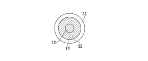
- FIG. 2 is a sectional view taken along the line C-C ′ of the embodiment of FIG. 1.
- FIG. 2 is a sectional view taken along the line D-D ′ of the embodiment of FIG. 1.
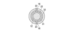
- FIG. 2 is an E-E ′ sectional view of the embodiment of FIG. 1.
- FIG. 2 is an F-F ′ cross-sectional view of the embodiment of FIG. 1.
- FIG. 2 is a G-G ′ sectional view of the embodiment of FIG. 1.
- FIG. 2 is an H-H ′ cross-sectional view of the embodiment of FIG. 1. It is the fragmentary sectional view which cut
- the toothbrush of the present invention includes a toothbrush handle body and a hair bundle.
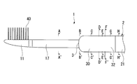
- a toothbrush 1 according to an embodiment of the present invention will be described with reference to FIGS. 1 to 6H, but the present invention is not limited to this.
- the toothbrush 1 shown in FIG. 1 is provided with a bristle bundle 40 on a long handle body 2.
- the toothbrush handle body 2 of this embodiment includes a handle portion 21, a neck portion 17 extending from the handle portion 21, and a head portion 11 provided at the tip of the neck portion 17.
- the shape is long in the direction from the handle portion 21 to the head portion 11.
- the neck portion 17 has a reduced diameter with respect to the handle portion 21.
- the boundary between the handle portion 21 and the neck portion 17 is referred to as a boundary portion 3.
- a part of the outer surface on the handle part 21 side from the boundary part 3 and the outer surface of the second member 20 is covered with a covering part 32.
- the length of the toothbrush handle body 2 of the present embodiment is not particularly limited, and is, for example, 120 to 200 mm.
- the width of the head portion 11 is not particularly limited, and is preferably 7 to 13 mm, and more preferably 8 to 12 mm, for example. If it is more than the said lower limit, the area which transplants the hair
- the width of the head portion means the maximum value of the length from the end portion to the end portion in the direction perpendicular to the length direction.
- the length of the head portion 11 is not particularly limited, and is preferably 10 to 30 mm, for example, and more preferably 12 to 28 mm.
- the length of the head portion means the length from the edge of the hair bundle 40 on the end portion 5 side to the tip of the head portion.
- the thickness of the head portion 11 can be determined in consideration of the material and the like. For example, the thickness is preferably 2 to 6 mm, and more preferably 2.5 to 4 mm. If it is more than the said lower limit, the intensity
- the thickness of the head portion means the minimum thickness of the head portion.
- the thickness of the neck portion 17 can be determined in consideration of the material and the like, and is preferably 3 to 6 mm, and more preferably 3.5 to 4.5 mm. If it is more than the said lower limit, the intensity
- the thickness of the neck portion means the minimum value of the diameter in a cross section when cut perpendicular to the length direction.
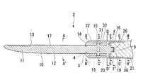
- the handle body 2 for a toothbrush of the present embodiment is formed with a first member 10 having a head portion 11 and an extending portion 12 extending from the head portion 11, and a handle portion 21.
- a second member 20 and a filling portion 31 made of an elastomer resin are provided.
- a part of the extending portion 12 (from the boundary portion 3 to the end portion 5 of the first member 10) is inserted into the cavity portion 4.
- the neck portion 17 is an exposed portion of the extended portion 12. Specifically, it means a portion from the edge of the hair bundle 40 on the end portion 5 side to the boundary portion 3.
- the filling portion 31 is provided between the first member 10 and the second member 20 in the cavity portion 4.
- the alphabets in FIG. 2 indicate locations corresponding to the locations indicated by the alphabets in FIG.
- bristle bundle 40 is abbreviate
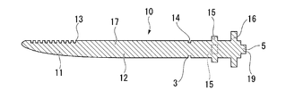
- a flock hole 13 is formed in the head portion 11.
- the extending portion 12 has a cylindrical shape.
- an annular recess 14, a first protrusion 15, and a second protrusion 15 are formed from the boundary 3 of the first member 10 to the end 5 of the extended portion 12.
- a convex portion 16 and a third convex portion 19 are provided in this order.
- the boundary portion 3 is formed with an annular recess 14 that goes around the extending portion 12.
- the annular recessed part 14 may be formed and does not need to be formed.
- the first convex portion 15 is a direction intersecting in the longitudinal direction from the extending portion 12, and the direction of the hair bundle 40 side and the back side thereof (vertical direction in FIG.
- the direction intersecting with the longitudinal direction means a direction perpendicular to the length direction. It is preferable that an opposing line connecting the first convex portions protruding in the four directions is provided so as to pass through the center of the extending portion 12. It is preferable that the opposing lines connecting the first protrusions protruding in the four directions intersect perpendicularly.
- the first convex portions 15 may be formed at the same interval in the circumferential direction of the extending portion, or may be formed at different intervals.
- the shape of the first convex portion 15 may be a prismatic shape or a cylindrical shape.
- the first convex portion 15 is preferably formed so that the center thereof is positioned 10 to 50 mm from the boundary portion 3.
- the first convex portion 15 is preferably formed so that the center thereof is positioned 10 to 50 mm from the end portion 5.
- the second convex portion 16 extends from the extending portion 12 in the longitudinal direction in the direction of the hair bundle 40 side and the back side thereof (up and down direction in FIG. 6D). Projects in two directions. It is preferable that a line connecting the second protrusions protruding in two directions passes through the center of the extension part 12.
- the shape of the second convex portion 16 may be a prismatic shape or a cylindrical shape.
- the 2nd convex part 16 may protrude in parallel with what protrudes in the direction of the hair
- the second convex portion 16 is preferably formed so that the center thereof is positioned 20 to 80 mm from the boundary portion 3.
- the second convex portion 16 is preferably formed so that the center thereof is positioned 10 to 50 mm from the end portion 5.
- the third convex portion 19 protrudes in the extending direction of the extending portion 12 at the end portion 5.
- the shape of the third convex portion 15 may be a prismatic shape or a cylindrical shape.
- the first member 10 is made of a first resin.
- the first resin is selected in consideration of the rigidity and mechanical characteristics required for the head portion 11 and the neck portion 17.
- the first resin include resins having a flexural modulus (JIS K7203) of 500 MPa or more and 3000 MPa or less.
- polyester such as PBT, polyethylene terephthalate (PET), polycyclohexylene dimethylene terephthalate (PCT); POM Polyolefins such as PP and polyethylene (PE); polystyrene (PS); acrylonitrile / butadiene / styrene resin (ABS), cellulose propionate (CP), polyarylate, polycarbonate, acrylonitrile / styrene copolymer resin (AS), etc.
- a resin mainly composed of one or more selected from polyester and POM is preferable, polyester and POM are more preferable, and PBT and POM are further preferable. Since polyester and POM have higher rigidity, sufficient strength can be obtained even if the head portion 11 is made thinner.
- main component means containing 50% by mass or more.
- the second member 20 of the present embodiment forms a handle portion 21 and has a long shape.
- the second member 20 is formed with a cavity 4 having an opening 25 in the direction of the neck 17.
- the cavity 4 is surrounded by a wall 22.
- the wall portion 22 is formed so that a part of the extending portion 12 (from the boundary portion 3 to the end portion 5 of the first member 10) can be inserted into the hollow portion 4.
- An extending slit 23 is formed.
- a first recess 26 is formed on the inner wall surface of the cavity 4 as viewed from the opening 25 side.
- the first concave portion 26 has a shape corresponding to the third convex portion 19.
- the second member 20 Since the thickness of the second member 2 is provided with the covering portion 32, the wall portion 22 and the vicinity thereof are thinner than the other portions (FIGS. 4, 6G, and 6H).
- the vicinity of the wall portion 22 means a portion of 10 to 50 mm from the wall portion 22 side in the handle portion.
- the second member 20 has a columnar shape behind the wall portion 22.
- the ratio of the diameter of the cross section obtained by cutting the thickest part of the handle portion in the width direction to the diameter of the cross section cut in the width direction in the vicinity of the wall portion 22 is preferably 10: 6 to 20:19.
- the ratio of the length of the wall portion to the length of the wall portion 22 and the vicinity thereof is preferably 20: 1 to 2: 1.
- the second member 20 is made of a second resin.
- the second resin is determined in consideration of the rigidity required for the handle portion 21 and the adhesiveness with the elastomer resin.
- the second resin include those similar to the first resin. Among these, polyolefin is preferable, and PP is more preferable. If it is polyolefin, the adhesiveness of the 2nd member 20 and elastomer resin can be improved.
- the second resin may be the same as or different from the first resin.
- the first resin is a resin mainly composed of one or more selected from polyester and POM, and the second resin is a polyolefin.
- the first resin is preferably PBT or POM, and the second resin is PP.
- the head portion 11 is made thinner, the extending portion 12 is made thinner to improve the operability in the oral cavity, and the adhesion between the second member 20 and the elastomer resin is improved. It is done.
- the first resin may be a non-translucent resin and the second resin may be a translucent resin. By setting it as such a combination, the design variation of the toothbrush handle body 2 can be diversified.
- the neck portion 17 is an exposed portion of the extended portion 12 (that is, a portion of the extended portion 12 excluding a portion from the boundary portion 3 to the end portion 5).
- the annular recess 14 is provided with an elastomer resin that constitutes the covering portion 32.
- all or part of the tip of the first convex portion 15 is in contact with the inner surface of the wall portion 22 in the hollow portion 4.
- the 1st convex part 15 does not need to be provided.
- flexibility of the movement of the 1st member 10 improves more by the filling part 31 which consists of elastomer resins, and a brushing pressure becomes more favorable.
- the shape of the tip of the first convex portion 15 preferably corresponds to the shape of the inner surface of the wall portion 22.
- the cross-sectional shape when cut in the width direction of the inner surface of the wall portion 22 is an arc shape
- the cross-sectional shape when cut in the width direction of the tip of the first convex portion 15 is also An arc shape is preferred.
- the height (thickness) of the first convex portion is preferably 0.1 to 2.0 mm, and more preferably 0.5 to 1.5 mm.
- the height (thickness) of the filling portion 31 corresponds to the height (thickness) of the first convex portion.
- the ratio of the height (thickness) of the filling portion 31 to the height (thickness) of the wall portion 22 is preferably 2: 1 to 20: 1.
- the ratio of the length of the neck portion 17 to the length of a part of the extended portion 12 (from the boundary portion 3 to the end portion 5 of the first member 10) is preferably 8: 5 to 8: 1.
- the second convex portion 16 passes through the wall portion 22 through the slit 23.
- the tip of the second convex portion 16 is flush with the outer surface of the covering portion 32.
- the width of the slit 23 may be the same as the width of the second protrusion 16 or may be wider than the width of the second protrusion 16.
- the height (thickness) of the second convex part 16 is the sum of the height (thickness) of the filling part 31, the height (thickness) of the wall part 22, and the height (thickness) of the covering part 32. Is preferably the same.
- the length of the slit may be the same as or different from the length of the wall portion 22.
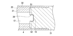
- a fitting structure is formed in which the third convex portion 19 is fitted into the first concave portion 26.
- the third convex portion 19 has a columnar shape
- the first concave portion 26 has a shape corresponding to the shape.
- the fitting structure may be an undercut structure.
- the undercut structure is such that the third protrusion 19 of the first member 10 has a columnar shape, and the fourth protrusion 51 in the circumferential direction of the side surface of the columnar shape. Is provided, and the second concave portion 52 corresponding to the fourth convex portion 51 is provided in the circumferential direction of the inner surface of the concave portion of the second member 20.
- the fourth convex portion 51 is inserted into the second concave portion 52, the first member 10 is less likely to be displaced not only in the direction intersecting the longitudinal direction but also in the longitudinal direction.
- an undercut structure is employ
- adopted the connection of the 1st member 10 and the 2nd member 20 can be strengthened more, and it can prevent that the 1st member 10 slips out of the 2nd member 20 at the time of use.
- a filling portion 31 is provided between the first member 10 and the second member 20 in the cavity portion 4.
- the filling portion 31 is made of an elastomer resin. That is, an elastomer resin is provided between the first member 10 and the second member 20 in the cavity 4.
- “between the first member 10 and the second member 20 in the cavity 4” is between the extended portion 12 and the wall portion 22 shown in FIGS. 6C to 6E.
- Examples of the type of elastomer resin constituting the filling portion 31 include olefin-based elastomers, styrene-based elastomers, polyester-based elastomers, polyurethane-based thermoplastic elastomers, and the like. Of these, styrene-based elastomers are preferable. Since the styrene elastomer is particularly excellent in elasticity, the operability in the oral cavity and the polishing comfort can be further enhanced. These resins may be used alone or in combination of two or more.
- the Shore hardness of the elastomer resin is preferably 10-60. The Shore hardness can be measured by the method of JIS K 6253 Shore A.
- the handle portion 21 is provided with a covering portion 32 in a region including the wall portion 22.
- the covering portion 32 is made of an elastomer resin, like the filling portion 31.
- the type of elastomer resin that constitutes the covering portion 32 is the same as that of the elastomer resin that constitutes the filling portion 31.
- the filling portion 31 and the covering portion 32 are connected through the slit 23 and the opening portion 25.
- the first member 10 and the second member 20 are mainly composed of a connection between the filling portion 31 and the covering portion 32 through the opening 25 and the slit 23, and an adhesive force or friction between the elastomer resin and the second member 20. It is firmly connected by force.
- the toothbrush 1 of the present embodiment includes the above-described toothbrush handle body 2 and a plurality of hair bundles 40 planted in the head portion 11.
- the hair bundle 40 is implanted in the flock hole 13 shown in FIG.
- the hair bundle 40 is a bundle of a plurality of hairs.
- the length (hair length) from the flocked surface of the head portion 11 to the tip of the hair bundle 40 can be determined in consideration of the hair and the like required for the hair bundle 40, and is, for example, 6 to 13 mm. All the hair bundles 40 may have the same hair length or may be different from each other.
- the thickness (hair bundle diameter) of the hair bundle 40 can be determined in consideration of the hair and the like required for the hair bundle 40, and is, for example, 1 to 3 mm. All the hair bundles 40 may have the same hair bundle diameter or may be different from each other.
- the diameter gradually decreases toward the hair tip the hair having a sharp hair tip (tapered hair), and the diameter is approximately from the flocked surface toward the hair tip.
- the hair for the same (straight hair) etc. are mentioned.
- Examples of the straight hair include those in which the hair tip is a flat surface substantially parallel to the flocked surface and those in which the hair tip is rounded into a hemisphere.
- the number of hairs for forming one hair bundle is preferably 10 to 180.
- the material of the hair is, for example, polyamide such as 6-12 nylon (6-12NY), 6-10 nylon (6-10NY), PET, PBT, polytrimethylene terephthalate (PTT), polyethylene naphthalate (PEN), Examples thereof include polyesters such as polybutylene naphthalate (PBN), polyolefins such as PP, elastomer resins such as polyolefin elastomers and styrene elastomers. These resin materials can be used singly or in combination of two or more.
- the bristle include polyester bristle having a multi-core structure having a core part and at least one or more sheath parts provided outside the core part.
- the cross-sectional shape of the hair is not particularly limited, and may be a circle such as a perfect circle or an ellipse, a polygon, a star, a three-leaf clover, a four-leaf clover, or the like.
- the cross-sectional shapes of all the hairs may be the same or different.
- the toothbrush handle body 2 is formed by insert molding or the like. For example, a first step of inserting a part of the extended portion 12 of the first member 10 into the cavity portion 4 of the second member 20, and a second step of filling the filling portion 31 with an elastomer resin. Thus, the toothbrush handle body 2 is obtained. Next, the hair bundle 40 is implanted in the head portion 11 of the toothbrush handle body 2 to obtain the toothbrush 1.
- the first member 10 and the second member 20 may be obtained by a known molding method such as injection molding.
- a known molding method such as injection molding.
- an example of the manufacturing method of the toothbrush 1 of this invention when performing a 2nd process by insert molding is demonstrated.
- the second member 20 is placed in the mold. Inside the mold, a cavity having a shape corresponding to the covering portion 32 is formed in a state where the first member 10 and the second member 20 are arranged.
- a part of the extended portion 12 of the first member 10 (from the boundary portion 3 to the end portion 5 of the first member 10) is moved so that the second convex portion 16 moves in the slit 23.
- the first member 10 is inserted into the cavity 4 of the member 20 (first step), and the tip of the third protrusion 19 is fitted into the first recess 26 of the second member 20.
- the mold is then closed.
- the first member 10 and the second member 20 are arranged in the mold, the first convex portion 15 comes into contact with the inner surface of the wall portion 22 of the second member 20, and the wall portion of the second convex portion 16. Since the tip protruding outside 22 contacts the mold, the first member 10 is not easily displaced when the elastomer resin is injected.
- the elastomer resin is injected into the mold in a state where the first member 10 and the second member 20 are disposed inside the mold.
- the elastomer resin injected into the mold passes through the slit 23 and the opening 25 and fills the filling portion 31 (second step).
- covers a part of handle part 21 and the outer side of the wall part 22 is formed by desired thickness.
- the first member 10 and the second member 20 are fixed to each other by providing the filling portion 31 and the covering portion 32 with the elastomer resin.
- the temperature of the mold when the elastomer resin is injected into the mold is preferably 20 to 80 ° C.
- a toothbrush is formed by performing a step (third step) of flocking the hair bundle 40 in the flock hole 13.
- the third step may be performed after the second step or may be performed before the first step.
- a method for flocking the hair bundle 40 the hair bundle 40 is folded in half, and a flat wire sandwiched between the two is driven into the flock hole 13 so that the hair bundle 40 is planted.
- the toothbrush handle body 2 and the toothbrush 1 that can be cleaned with an appropriate brushing pressure are obtained.
- the use of an elastomer resin, which is a highly flexible resin, in the filling portion 31 reduces the brushing pressure during use. Therefore, if the toothbrush 1 of this embodiment is used, since the bristle bundle 40 can be appropriately brought into contact with the site to be cleaned and cleaned with an appropriate brushing pressure, the scrubbing effect is further enhanced.
- the first member 10 is formed in order to make the head portion 11 small, the head portion 11 thin, or the neck portion 17 further narrowed. Even if a high-strength resin such as POM is used, cleaning can be performed with a more appropriate brushing pressure, and a good scrubbing effect can be obtained. In the present embodiment, if a high-strength resin such as POM is used for the first member 10, the head portion 11 is damaged when the hair bundle 40 is implanted by flat-wire-type flocking, and the strength of the head portion 11 is reduced. It is possible to prevent damage to the head portion 11 during use.
- a high-strength resin such as POM
- the first convex portion 15 comes into contact with the inner surface of the wall portion 22 and passes through the slit 23. Since the tip of the second convex portion 16 penetrating the wall portion 22 comes into contact with the mold, a deviation that may occur in the direction in which the first member 10 intersects the longitudinal direction occurs when the elastomer resin is injected. Hateful.
- a through-hole through which the elastomer resin can pass between the boundary portion 3 and the end portion 5 of the extending portion 12 of the present embodiment for example, in the direction of the hair bundle 40 side and the back side thereof. During production, the elastomer resin is easily filled. Further, by providing the elastomer resin in the through hole, the connection between the first member 10 and the second member 20 is further strengthened.
- the present invention is not limited to the embodiment described above.
- the 1st convex part 15 may be provided and does not need to be provided.
- the first convex portion 15 is provided, and that at least two locations are provided. More preferred. More preferably, at least four places are provided.
- the 2nd convex part 16 may be provided and does not need to be provided.
- the 2nd convex part 16 is provided, and it is more preferable that at least 2 places are provided.
- the end portion 5 other than the tip of the third convex portion 19 abuts on the second member 20. If the clearance is provided and the clearance is provided (see FIG. 7), the elastomer resin is filled in the clearance, so that the amount of deflection of the neck portion 17 during use can be further increased.
- bristle bundle 40 can be further contact
- the covering portion 32 may or may not be provided.
- the first member 10 and the second member 20 are more firmly connected to each other, and the fingers 32 are less likely to slip during use, so that the covering portion 32 is preferably provided.
- the thickness of the covering portion 32 is preferably 0.5 to 2.0 mm.
- the slit 23 may or may not be formed.
- the 2nd convex part 16 in order to make it easy to insert the 1st member 10 in the 2nd member 20 in the case of manufacture, it is preferable that the slit 23 is formed.
- the slit 23 is not formed. In the case where the slit 23 is not formed, it is preferable to form a through hole in the wall portion 22 through which the elastomer resin can pass in order to make it easy to fill the filling portion 31 with the elastomer resin during manufacturing.
- the extension part 12 is cylindrical, in this invention, an extension part is not restricted to a column shape.
- the extending portion include a polygonal column shape. In the case of a polygonal column shape, the corners are preferably rounded. That is, the extending portion 12 can select a desired shape as long as the effects of the present invention are not lost.
- the second member 20 is cylindrical, but in the present invention, the second member is not limited to a cylindrical shape. Examples of other aspects of the second member include a polygonal column shape. In the case of a polygonal column shape, the corners are preferably rounded. That is, the desired shape of the second member 20 can be selected as long as the effects of the present invention are not lost.
- the manufacturing method of the handle body for toothbrushes, the toothbrush, and the toothbrush handle body excellent in the bending of a neck part at the time of use can be provided.
Landscapes
- Brushes (AREA)
Abstract
Priority Applications (3)
| Application Number | Priority Date | Filing Date | Title |
|---|---|---|---|
| JP2016507847A JPWO2015137487A1 (ja) | 2014-03-14 | 2015-03-13 | 歯ブラシ用ハンドル体、歯ブラシ、及び歯ブラシ用ハンドル体の製造方法 |
| CN201580013085.XA CN106102514A (zh) | 2014-03-14 | 2015-03-13 | 牙刷用柄体、牙刷、以及牙刷用柄体的制造方法 |
| KR1020167019599A KR20160134643A (ko) | 2014-03-14 | 2015-03-13 | 칫솔용 핸들체, 칫솔, 및 칫솔용 핸들체의 제조방법 |
Applications Claiming Priority (2)
| Application Number | Priority Date | Filing Date | Title |
|---|---|---|---|
| JP2014-051551 | 2014-03-14 | ||
| JP2014051551 | 2014-03-14 |
Publications (1)
| Publication Number | Publication Date |
|---|---|
| WO2015137487A1 true WO2015137487A1 (fr) | 2015-09-17 |
Family
ID=54071923
Family Applications (1)
| Application Number | Title | Priority Date | Filing Date |
|---|---|---|---|
| PCT/JP2015/057481 Ceased WO2015137487A1 (fr) | 2014-03-14 | 2015-03-13 | Manche de brosse à dents, brosse à dents, et procédé de fabrication de brosse à dents |
Country Status (4)
| Country | Link |
|---|---|
| JP (1) | JPWO2015137487A1 (fr) |
| KR (1) | KR20160134643A (fr) |
| CN (1) | CN106102514A (fr) |
| WO (1) | WO2015137487A1 (fr) |
Cited By (2)
| Publication number | Priority date | Publication date | Assignee | Title |
|---|---|---|---|---|
| KR20200090938A (ko) * | 2016-03-09 | 2020-07-29 | 라이온 가부시키가이샤 | 칫솔 |
| KR20200106228A (ko) * | 2016-03-09 | 2020-09-11 | 라이온 가부시키가이샤 | 칫솔 |
Families Citing this family (1)
| Publication number | Priority date | Publication date | Assignee | Title |
|---|---|---|---|---|
| JP7370179B2 (ja) * | 2019-06-28 | 2023-10-27 | ライオン株式会社 | 歯ブラシ |
Citations (7)
| Publication number | Priority date | Publication date | Assignee | Title |
|---|---|---|---|---|
| JP2831401B2 (ja) * | 1988-11-29 | 1998-12-02 | ブレンダックス、ゲゼルシャフト、ミット、ベシュレンクテル、ハフツング | 歯ブラシ |
| JP2000004944A (ja) * | 1998-06-26 | 2000-01-11 | Lion Corp | 歯ブラシ |
| JP2000510711A (ja) * | 1995-03-23 | 2000-08-22 | スミスクライン・ビーチャム・コンシューマー・ヘルスケア・ゲゼルシャフト・ミット・ベシュレンクテル・ハフツング | 歯ブラシ |
| JP2001517512A (ja) * | 1997-09-26 | 2001-10-09 | スミスクライン・ビーチャム・ゲゼルシャフト・ミット・ベシュレンクテル・ハフツング・ウント・コムパニー・コマンディットゲゼルシャフト | 歯ブラシ |
| JP2003500091A (ja) * | 1999-05-24 | 2003-01-07 | グラクソスミスクライン・コンシューマー・ヘルスケア・ゲゼルシャフト・ミット・ベシュレンクテル・ハフツング・ウント・コムパニー・コマンディットゲゼルシャフト | 歯ブラシ |
| JP2003516782A (ja) * | 1999-12-14 | 2003-05-20 | グラクソスミスクライン・コンシューマー・ヘルスケア・ゲゼルシャフト・ミット・ベシュレンクテル・ハフツング・ウント・コムパニー・コマンディットゲゼルシャフト | 歯ブラシ |
| JP2004538029A (ja) * | 1999-12-14 | 2004-12-24 | グラクソスミスクライン・コンシューマー・ヘルスケア・ゲゼルシャフト・ミット・ベシュレンクテル・ハフツング・ウント・コムパニー・コマンディットゲゼルシャフト | 歯ブラシ |
Family Cites Families (8)
| Publication number | Priority date | Publication date | Assignee | Title |
|---|---|---|---|---|
| JP3387591B2 (ja) | 1993-11-22 | 2003-03-17 | ジョンソン・エンド・ジョンソン株式会社 | 歯ブラシ |
| JPH10215950A (ja) * | 1997-02-03 | 1998-08-18 | Lion Corp | ブラッシング圧コントロール歯ブラシ |
| US6502272B1 (en) * | 2000-05-24 | 2003-01-07 | Colgate-Palmolive Company | Replaceable head toothbrush providing controlled brushing pressure |
| NO322158B1 (no) * | 2002-07-26 | 2006-08-21 | Jordan As | Tannborste |
| JP2005144033A (ja) * | 2003-11-19 | 2005-06-09 | Lion Corp | 歯ブラシ |
| GB201104024D0 (en) * | 2011-03-09 | 2011-04-20 | Glaxosmithkline Consumer Healt | Novel device |
| JP5806922B2 (ja) | 2011-12-07 | 2015-11-10 | ライオン株式会社 | 歯ブラシ |
| JP6170802B2 (ja) * | 2013-10-02 | 2017-07-26 | ライオン株式会社 | 歯ブラシ用のハンドル体及びその製造方法ならびに歯ブラシ |
-
2015
- 2015-03-13 WO PCT/JP2015/057481 patent/WO2015137487A1/fr not_active Ceased
- 2015-03-13 JP JP2016507847A patent/JPWO2015137487A1/ja not_active Ceased
- 2015-03-13 KR KR1020167019599A patent/KR20160134643A/ko not_active Withdrawn
- 2015-03-13 CN CN201580013085.XA patent/CN106102514A/zh active Pending
Patent Citations (7)
| Publication number | Priority date | Publication date | Assignee | Title |
|---|---|---|---|---|
| JP2831401B2 (ja) * | 1988-11-29 | 1998-12-02 | ブレンダックス、ゲゼルシャフト、ミット、ベシュレンクテル、ハフツング | 歯ブラシ |
| JP2000510711A (ja) * | 1995-03-23 | 2000-08-22 | スミスクライン・ビーチャム・コンシューマー・ヘルスケア・ゲゼルシャフト・ミット・ベシュレンクテル・ハフツング | 歯ブラシ |
| JP2001517512A (ja) * | 1997-09-26 | 2001-10-09 | スミスクライン・ビーチャム・ゲゼルシャフト・ミット・ベシュレンクテル・ハフツング・ウント・コムパニー・コマンディットゲゼルシャフト | 歯ブラシ |
| JP2000004944A (ja) * | 1998-06-26 | 2000-01-11 | Lion Corp | 歯ブラシ |
| JP2003500091A (ja) * | 1999-05-24 | 2003-01-07 | グラクソスミスクライン・コンシューマー・ヘルスケア・ゲゼルシャフト・ミット・ベシュレンクテル・ハフツング・ウント・コムパニー・コマンディットゲゼルシャフト | 歯ブラシ |
| JP2003516782A (ja) * | 1999-12-14 | 2003-05-20 | グラクソスミスクライン・コンシューマー・ヘルスケア・ゲゼルシャフト・ミット・ベシュレンクテル・ハフツング・ウント・コムパニー・コマンディットゲゼルシャフト | 歯ブラシ |
| JP2004538029A (ja) * | 1999-12-14 | 2004-12-24 | グラクソスミスクライン・コンシューマー・ヘルスケア・ゲゼルシャフト・ミット・ベシュレンクテル・ハフツング・ウント・コムパニー・コマンディットゲゼルシャフト | 歯ブラシ |
Cited By (4)
| Publication number | Priority date | Publication date | Assignee | Title |
|---|---|---|---|---|
| KR20200090938A (ko) * | 2016-03-09 | 2020-07-29 | 라이온 가부시키가이샤 | 칫솔 |
| KR20200106228A (ko) * | 2016-03-09 | 2020-09-11 | 라이온 가부시키가이샤 | 칫솔 |
| KR102384895B1 (ko) | 2016-03-09 | 2022-04-11 | 라이온 가부시키가이샤 | 칫솔 |
| KR102418461B1 (ko) | 2016-03-09 | 2022-07-08 | 라이온 가부시키가이샤 | 칫솔 |
Also Published As
| Publication number | Publication date |
|---|---|
| KR20160134643A (ko) | 2016-11-23 |
| CN106102514A (zh) | 2016-11-09 |
| JPWO2015137487A1 (ja) | 2017-04-06 |
Similar Documents
| Publication | Publication Date | Title |
|---|---|---|
| JP6170802B2 (ja) | 歯ブラシ用のハンドル体及びその製造方法ならびに歯ブラシ | |
| KR102577531B1 (ko) | 칫솔 | |
| JP6385027B1 (ja) | 歯ブラシ | |
| TWI766856B (zh) | 牙刷 | |
| JP5879118B2 (ja) | 歯ブラシ | |
| KR20180058218A (ko) | 칫솔 | |
| JPWO2016199853A1 (ja) | 歯ブラシ | |
| WO2017155045A1 (fr) | Brosse à dents | |
| WO2017169967A1 (fr) | Corps de manche pour brosse à dents et brosse à dents | |
| JP7203882B2 (ja) | 歯ブラシ | |
| WO2015137487A1 (fr) | Manche de brosse à dents, brosse à dents, et procédé de fabrication de brosse à dents | |
| JP6478384B2 (ja) | 歯ブラシ用ハンドル体及び歯ブラシ | |
| KR102737286B1 (ko) | 칫솔 | |
| JP5785819B2 (ja) | 歯ブラシ | |
| JP2003144232A (ja) | 歯ブラシハンドルの製造方法 | |
| JPWO2019230845A1 (ja) | 歯ブラシ | |
| JP6858123B2 (ja) | 歯ブラシ | |
| JP5977942B2 (ja) | 歯ブラシ | |
| KR20200051640A (ko) | 칫솔 | |
| JP2024054019A (ja) | 歯ブラシ | |
| JP2018075269A (ja) | 歯ブラシ |
Legal Events
| Date | Code | Title | Description |
|---|---|---|---|
| 121 | Ep: the epo has been informed by wipo that ep was designated in this application |
Ref document number: 15762198 Country of ref document: EP Kind code of ref document: A1 |
|
| ENP | Entry into the national phase |
Ref document number: 2016507847 Country of ref document: JP Kind code of ref document: A |
|
| ENP | Entry into the national phase |
Ref document number: 20167019599 Country of ref document: KR Kind code of ref document: A |
|
| NENP | Non-entry into the national phase |
Ref country code: DE |
|
| WWE | Wipo information: entry into national phase |
Ref document number: IDP00201606132 Country of ref document: ID |
|
| 122 | Ep: pct application non-entry in european phase |
Ref document number: 15762198 Country of ref document: EP Kind code of ref document: A1 |