WO2015140843A1 - 情報処理装置、影響過程抽出方法および記録媒体 - Google Patents
情報処理装置、影響過程抽出方法および記録媒体 Download PDFInfo
- Publication number
- WO2015140843A1 WO2015140843A1 PCT/JP2014/003227 JP2014003227W WO2015140843A1 WO 2015140843 A1 WO2015140843 A1 WO 2015140843A1 JP 2014003227 W JP2014003227 W JP 2014003227W WO 2015140843 A1 WO2015140843 A1 WO 2015140843A1
- Authority
- WO
- WIPO (PCT)
- Prior art keywords
- time
- abnormality
- information
- relationship
- information processing
- Prior art date
- Legal status (The legal status is an assumption and is not a legal conclusion. Google has not performed a legal analysis and makes no representation as to the accuracy of the status listed.)
- Ceased
Links
Images






Classifications
-
- G—PHYSICS
- G06—COMPUTING OR CALCULATING; COUNTING
- G06F—ELECTRIC DIGITAL DATA PROCESSING
- G06F11/00—Error detection; Error correction; Monitoring
- G06F11/30—Monitoring
- G06F11/34—Recording or statistical evaluation of computer activity, e.g. of down time, of input/output operation ; Recording or statistical evaluation of user activity, e.g. usability assessment
- G06F11/3447—Performance evaluation by modeling
-
- G—PHYSICS
- G06—COMPUTING OR CALCULATING; COUNTING
- G06F—ELECTRIC DIGITAL DATA PROCESSING
- G06F11/00—Error detection; Error correction; Monitoring
- G06F11/30—Monitoring
- G06F11/34—Recording or statistical evaluation of computer activity, e.g. of down time, of input/output operation ; Recording or statistical evaluation of user activity, e.g. usability assessment
- G06F11/3466—Performance evaluation by tracing or monitoring
- G06F11/3476—Data logging
-
- H—ELECTRICITY
- H04—ELECTRIC COMMUNICATION TECHNIQUE
- H04L—TRANSMISSION OF DIGITAL INFORMATION, e.g. TELEGRAPHIC COMMUNICATION
- H04L41/00—Arrangements for maintenance, administration or management of data switching networks, e.g. of packet switching networks
- H04L41/06—Management of faults, events, alarms or notifications
- H04L41/0631—Management of faults, events, alarms or notifications using root cause analysis; using analysis of correlation between notifications, alarms or events based on decision criteria, e.g. hierarchy, tree or time analysis
-
- H—ELECTRICITY
- H04—ELECTRIC COMMUNICATION TECHNIQUE
- H04L—TRANSMISSION OF DIGITAL INFORMATION, e.g. TELEGRAPHIC COMMUNICATION
- H04L41/00—Arrangements for maintenance, administration or management of data switching networks, e.g. of packet switching networks
- H04L41/06—Management of faults, events, alarms or notifications
- H04L41/0677—Localisation of faults
-
- H—ELECTRICITY
- H04—ELECTRIC COMMUNICATION TECHNIQUE
- H04L—TRANSMISSION OF DIGITAL INFORMATION, e.g. TELEGRAPHIC COMMUNICATION
- H04L63/00—Network architectures or network communication protocols for network security
- H04L63/14—Network architectures or network communication protocols for network security for detecting or protecting against malicious traffic
- H04L63/1408—Network architectures or network communication protocols for network security for detecting or protecting against malicious traffic by monitoring network traffic
- H04L63/1416—Event detection, e.g. attack signature detection
-
- H—ELECTRICITY
- H04—ELECTRIC COMMUNICATION TECHNIQUE
- H04L—TRANSMISSION OF DIGITAL INFORMATION, e.g. TELEGRAPHIC COMMUNICATION
- H04L63/00—Network architectures or network communication protocols for network security
- H04L63/14—Network architectures or network communication protocols for network security for detecting or protecting against malicious traffic
- H04L63/1408—Network architectures or network communication protocols for network security for detecting or protecting against malicious traffic by monitoring network traffic
- H04L63/1425—Traffic logging, e.g. anomaly detection
-
- G—PHYSICS
- G06—COMPUTING OR CALCULATING; COUNTING
- G06F—ELECTRIC DIGITAL DATA PROCESSING
- G06F2201/00—Indexing scheme relating to error detection, to error correction, and to monitoring
- G06F2201/875—Monitoring of systems including the internet
Definitions
- the present invention relates to an information processing apparatus, an influence process extraction method, and a recording medium.
- Patent Document 1 describes an attack determination device that estimates an attack source and an attack path of an attack on a monitored network using a plurality of types of evaluation parameters based on a log generated by a device in the monitored network. ing.
- Patent Document 2 describes a method of detecting a fault location using a dependency graph that formally expresses a dependency relationship between services latent in a network.
- the method is a method of detecting a failure location by tracing a dependency relationship on a dependency graph and extracting and limiting a set of services on a network device that causes a failure or affects the failure. .
- JP 2010-152773 A Japanese Patent Laid-Open No. 11-259331
- the present invention has been made in view of the above problems, and an object of the present invention is to provide an information processing apparatus that more appropriately extracts an abnormality influencing process even when an abnormality is found at a plurality of locations. It is in.
- An information processing apparatus is a relationship graph representing a relationship between a plurality of elements included in a system, and information indicating a position on the system where an abnormality is detected, on the relationship graph Using the position information indicating the plurality of positions of the plurality of positions, starting from each of the plurality of positions, a path on the relation graph including the set of elements having a direct or indirect relationship from the position
- An information processing apparatus is a relationship graph representing a relationship between a plurality of elements included in a system, and information indicating a position on the system where an abnormality is detected, on the relationship graph
- the element having a relationship directly or indirectly from the position, starting from the position, using an acquisition means for acquiring position information indicating the position of the position, and the relationship graph and the position information acquired by the acquisition means Reachable range extraction means for extracting a path on the relation graph consisting of a set of as an influence process of abnormality.
- An influence process extraction method includes a relationship graph representing a relationship between a plurality of elements included in a system, and information indicating a position on the system where an abnormality is detected, the relationship graph Using the position information indicating the plurality of positions above, starting from each of the plurality of positions, the route on the relation graph consisting of the set of elements having a direct or indirect relationship from the position is reached.
- An influence process of an abnormality is extracted by extracting a range that is common to a predetermined number or more of a plurality of routes on the relationship graph extracted as a range and extracted as the reach range.
- An influence process extraction method is an influence process extraction method for an information processing device, which is a relation graph representing a relationship between a plurality of elements included in a system, and on the system where an abnormality is detected.
- the position information indicating the position of the relationship graph is acquired, and the position information indicating the position on the relationship graph is acquired, and using the acquired relationship graph and the position information, the position is used as a starting point, directly or indirectly from the position.
- a path on the relation graph consisting of the set of elements having a relation is extracted as an abnormal influence process.
- FIG. 1 is a diagram showing an example of the configuration of the information processing apparatus 100 according to the first embodiment of the present invention.
- the information processing apparatus 100 includes a reach range extraction unit 110 and a common range extraction unit 120.
- FIG. 2 is a diagram illustrating an example of the configuration of the information processing system 1 according to the present embodiment.
- the information processing system 1 includes an information processing apparatus 100 and a monitoring target system (also simply referred to as “system”) 900.
- the information processing apparatus 100 and the monitoring target system 900 are connected via a network (not shown).
- a plurality of monitoring target systems 900 may be connected to the information processing apparatus 100.
- the monitored system 900 includes a plurality of elements 920. Each of the elements 920 has some relationship with each of the other elements 920.
- the monitoring target system 900 is an information processing system that includes a plurality of hosts (not shown) connected via a network, and a process (not shown) operates on the hosts.
- the monitoring target system 900 may be a social network.
- the monitoring target system 900 may be a set of data items (elements 920) having a certain structure.
- a set of data items having some structure is, for example, a set of files having a relationship between a hyperlink and a hyperlink.
- the monitoring target system 900 may be an arbitrary system.
- the reach range extraction unit 110 illustrates a relationship graph representing a relationship between a plurality of nodes (also referred to as elements) included in the monitoring target system 900 and information (position information) indicating a plurality of positions on the relationship graph. Not received from external device. This position information is information indicating a position on the monitoring target system 900 where an abnormality is detected.
- the reachable range extraction unit 110 may be configured to acquire the relationship graph and the position information from other means (not shown) in the information processing apparatus 100.
- the method for acquiring the relationship graph and the position information is not particularly limited.
- FIG. 3 is a diagram illustrating an example of a relationship graph representing a relationship between a plurality of elements included in the monitoring target system 900.
- the relationship graph is a graph in which each of the elements 920 is a vertex (also referred to as an element or a node), and the relationship between the elements 920 is an edge (also referred to as a link, an edge, or a branch).
- the relationship graph represents the relationship between the elements 920 in the monitoring target system 900.
- the relationship is, for example, a data transmission relationship that “data is transmitted between elements in a certain period” or a state in which data transmission can be performed between elements at a certain moment (or period).
- Data transmission relationship As shown in FIG. 3, the relationship graph is composed of records including vertex identifiers and edges.
- the vertex identifier is an identifier of the element 920 that becomes the vertex.
- the side is information indicating a relationship between a vertex (element 920) specified by each vertex identifier and another vertex (element 920).
- the vertex identifier “E1” specifies the element 920 whose identifier is “E1”. Then, “E2; L0, E3; L1; L1” on the side corresponding to the vertex identifier “E1” indicates the following. First, the element 920 “E1” has a side representing the relationship with the element 920 “E2”, and the attribute of the side is “L0”. Second, the element 920 “E1” has two sides representing the relationship with the element 920 “E3”, and the attributes of these sides are both “L1”.
- the fact that the side is blank indicates that the element 920 “E4” has no side (does not relate to) any other element 920.
- the side indicates, for example, that the preparation for executing communication is completed between the elements 920 having the side.
- the attribute of the side indicates, for example, a protocol type of communication executed on the side.
- the side and the type of side are not limited to the above-described example, and may be any definition that indicates the relationship between the elements 920.
- the relationship graph may be a relationship graph in an arbitrary format regardless of the above-described example.
- FIG. 4 is a conceptual diagram showing the relationship between the elements 920 represented by the relationship graph.
- the vertices are shown as circles, and the vertex identifiers are shown in the circles.
- the sides are indicated by line segments connecting the circles.
- a line segment indicated by a solid line indicates a side whose type is “L0”.
- a line segment indicated by an alternate long and short dash line indicates a side whose type is “L1”.
- a line segment indicated by a two-dot chain line indicates an edge of type “L2”.
- An arrow indicates a direction from the side that generates the relationship to the outside.
- relationship graph may be shown in an arbitrary format regardless of the above example.
- the relationship graph may take a data structure such as an adjacency list or an adjacency matrix.
- the reach range extraction unit 110 acquires information indicating an element and / or information indicating a side as position information.
- the information indicating the element is, for example, a vertex identifier.
- the information indicating the side is information represented by vertex identifiers connected to both ends of the side, for example. Note that the position information is not limited to these, and may be information indicating the position on the relationship graph.
- the position on the monitoring target system 900 where an abnormality is detected is, for example, the position on the monitoring target system 900 where it is detected that infection has occurred. It is not limited to.
- the reach range extraction unit 110 extracts a path on the relation graph including a set of elements that are directly or indirectly related from the position, starting from each position on the relation graph indicated by the position information. To do.
- the reach range extraction unit 110 scans and extracts a path (a range having a direct or indirect relationship with the start point) on the relation graph reaching from each start point using a backtrace or the like.
- the back trace is to trace the directed edge in the reverse direction when the relation graph is a directed graph.
- the back trace is also called backward search.
- the route extraction method is not limited to the above, and may be, for example, the Dijkstra method. Then, the reach range extraction unit 110 supplies the common range extraction unit 120 with the paths (reach ranges) on the relationship graph extracted for each position on the relationship graph where the abnormality is detected.
- the common range extraction unit 120 receives, from the reach range extraction unit 110, a route on the relationship graph extracted for each position on the relationship graph where an abnormality is detected. Then, the common range extraction unit 120 extracts a common range among a plurality of routes on the extracted relation graph by a predetermined number of routes or more.
- the extracted common range may be an element, a side, or a set of these. Then, the common range extraction unit 120 extracts an abnormal influence process from the extracted common range.
- the predetermined number or more of routes may be all routes or a predetermined number or proportion of routes.
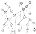
- FIG. 5 is a diagram for explaining the operation of the information processing apparatus 100.
- the diagram shown in FIG. 5 is an example of a relationship graph.
- the relationship graph shown in FIG. 5 includes elements indicated by vertex identifiers E1 to E22, C1 and C2, and directed line segments (sides) connecting the elements.
- elements indicated by vertex identifiers E1 to E22 are indicated by circles, and elements indicated by vertex identifiers C1 and C2 are indicated by squares.
- the reach range extraction unit 110 starts from C1 and is a path on the relation graph that reaches from C1. To extract. Then, the reach range extraction unit 110 extracts the range (route) surrounded by the one-dot chain line in FIG. 5 as the reach range that reaches from C1.
- the reach range extraction unit 110 extracts a route (reach range) on the relation graph reaching from C2 with C2 as a starting point. And the reach range extraction part 110 extracts the range enclosed with the broken line of FIG. 5 as the reach range from C2.
- the reach range extraction unit 110 supplies information indicating the reach range from C1 and information indicating the reach range from C2 to the common range extractor 120.
- the common range extraction unit 120 extracts a common range between the two supplied ranges. As shown in FIG. 5, the range common to the range surrounded by the alternate long and short dash line and the range surrounded by the broken line is a portion including elements (E11 to E14) indicated by hatching.
- the common range extraction unit 120 extracts the influence process of the abnormality from the extracted common range. For example, in FIG. 5, a route between E5 and E14 is assumed for E6 included in the reach from C1. Here, since the common range is E14, the common range extraction unit 120 extracts that the path affected by the abnormality from E6 is the path E14 out of E5 and E14. As described above, the common range extraction unit 120 can extract the abnormal influence process using the extracted common range.
- the range that the common range extraction unit 120 extracts as the common range may be a plurality of elements or a single element.
- the common range extraction unit 120 may extract a side connecting the elements as a common range.
- the description has been given by taking as an example that there are two positions on the relation graph where an abnormality is detected, but the present invention is not limited to this. There may be a plurality of positions on the relation graph where the abnormality is detected. Further, in the present embodiment, the description has been given by taking as an example that the position on the relation graph where the abnormality is detected is an element, but the present invention is not limited to this. The position where the abnormality is detected may be a side.
- effect According to the information processing apparatus 100 according to the present embodiment, it is possible to more appropriately extract an abnormality influencing process even when an abnormality is found at a plurality of locations.
- the reach range extraction unit 110 uses the relationship graph and information indicating the position on the monitoring target system 900 where the abnormality is detected, and using the position information indicating the plurality of positions on the relationship graph, This is because, starting from each position, a route on the relation graph composed of the set of elements having a direct or indirect relationship from the position is extracted as a reachable range. Then, the common range extraction unit 120 extracts the influence process of the abnormality by extracting a plurality of extracted routes that are common to a predetermined number or more of the routes on the relation graph. Because.
- the reach range extraction unit 110 uses the relation graph from the position on the monitoring target system 900 where the abnormality is detected to extract the range that reaches from the position, so that the abnormality affects which range of the system. Can be extracted.
- the common range extraction unit 120 extracts an abnormal influence process by extracting a range common to a predetermined number or more of routes from each of a plurality of positions on the relation graph where the abnormality is detected. By doing so, it is possible to easily extract the abnormal influence process.
- the information processing apparatus 100 arrives from the position where the abnormality is detected by performing backtrace from a plurality of positions (C1 and C2 in FIG. 5) on the relation graph where the abnormality is detected.
- the reach range extraction unit 110 of the information processing apparatus 100 may extract the reach range by performing forward tracing from the position where the abnormality is detected.
- forward tracing refers to tracing a directed edge in the positive direction when the relation graph is a directed graph.
- forward tracing is also referred to as forward search.
- the information processing apparatus 100 can extract the abnormal influence process more suitably.
- FIG. 6 is a functional block diagram illustrating an example of a functional configuration of the information processing apparatus 101 according to the present embodiment.
- the information processing apparatus 101 includes a common range extraction unit 120 and a reach range extraction unit 130.
- the information processing apparatus 101 according to the present embodiment includes a reach range extracting unit 130 instead of the reach range extracting unit 110 in the information processing apparatus 100 according to the first embodiment as illustrated in FIG. I have.
- the reach range extraction unit 130 is a relationship graph representing a relationship between a plurality of elements included in the monitoring target system 900, and information indicating a position on the monitoring target system 900 where an abnormality has been detected. Position information indicating a plurality of positions is received from an external device (not shown).
- the position information indicating the position on the relation graph where the abnormality in the first embodiment described above is detected is a plurality of positions on the monitoring target system 900 where the occurrence of the abnormality is detected, and Although description has been given taking as an example the position information indicating a plurality of positions on the graph, the present invention is not limited to this.
- the position information used in the present embodiment is different from the position information input to the information processing apparatus 100 in the first embodiment.
- the position information includes information (first position information) indicating one or a plurality of positions on the relation graph where the occurrence of the abnormality is detected, and on the relation graph detected as a possibility of the cause of the abnormality.
- Information indicating the one or more positions (second position information).
- the first position information and the second position information are not limited to this, and may be information detected as an abnormality, and the contents of the abnormality may be different.
- the position on the relation graph where the occurrence of the abnormality is detected is, for example, the position on the relation graph where the infection with malware or the like is detected.
- the position on the relationship graph that may be the cause of the abnormality may be, for example, a position on the relationship graph that indicates an element that is detected as having the possibility of being vulnerable, It may be a position on a relation graph indicating an element or the like detected as performing a different behavior.
- the reachable range extraction unit 130 may be configured to acquire the relationship graph and the position information from other means (not shown) in the information processing apparatus 101. The method for acquiring the relationship graph and the position information is not particularly limited.
- the reach range extraction unit 130 includes a first extraction unit 131 and a second extraction unit 132, as shown in FIG.
- the 1st extraction part 131 extracts the range on the relationship graph which reaches
- the second extraction unit 132 uses the method different from the first position information from the other position information (for example, the second position information) as a reachable range on the relation graph. Extract.
- FIG. 7 is a diagram for explaining the operation of the reach range extraction unit 130 in the information processing apparatus 101.
- the diagram shown in FIG. 7 is an example of a relationship graph.
- the relation graph shown in FIG. 7 includes elements indicated by vertex identifiers E1 to E11, E13 to 23, C1 and C3, and directed line segments (sides) connecting the elements.
- elements indicated by vertex identifiers E1 to E11 and E13 to E23 are indicated by circles
- elements indicated by vertex identifiers C1 and C3 are indicated by graphics indicating files.
- the first extraction unit 131 of the reach range extraction unit 130 scans a range on the relation graph that reaches from C1, starting from C1.
- the method in which the 1st extraction part 131 scans the range on the relationship graph which arrives from C1 is assumed to be a back trace, for example, this invention is not limited to this.
- the 1st extraction part 131 extracts that it is the range (1st reachable range) which reaches
- the second extraction unit 132 of the reach range extraction unit 130 scans a range on the relation graph that arrives from C3, starting from C3.
- the method in which the second extraction unit 132 scans the range on the relation graph reaching from C3 is, for example, forward tracing, but the present invention is not limited to this.
- the second extraction unit 132 only needs to scan the range using a method different from that of the first extraction unit 131.
- the 2nd extraction part 132 extracts that it is the range (2nd reachable range) which reaches
- the common range extracting unit 120 extracts a common range between the first reachable range and the second reachable range extracted by the reachable range extracting unit 130 as a common range.
- the common range between the range surrounded by the alternate long and short dash line and the range surrounded by the broken line is a portion including elements (E6 to 8, E13, E14, C3, C1) indicated by hatching. . Therefore, the common range extraction unit 120 extracts the common range described by the oblique lines as an abnormal influence process.
- the path (abnormal influence process) between the position on the relation graph indicated by the first position information and the position on the relation graph indicated by the second position information is shown.
- the route is extracted by, for example, the bidirectional Dijkstra method using the position on the relation graph indicated by the first position information and the position on the relation graph indicated by the second position information. It may be.
- the route extraction method is not particularly limited.
- effect According to the information processing apparatus 101 according to the present embodiment, it is possible to more appropriately extract an abnormality influencing process even when an abnormality is found at a plurality of locations.
- the reach extraction unit 130 starts a path on a relation graph including a set of elements that are directly or indirectly related from the positions (1) and (2) below. This is because it is extracted as a reachable range.
- the reach range extraction unit 130 starts from each position on the relation graph where the abnormality is detected even when the contents of the abnormality found in a plurality of places are different. In addition, it is possible to extract a range reaching from the position.
- the common range extraction unit 120 extracts the path between the positions on the relation graph indicated by the first and second position information as an abnormal influence process.
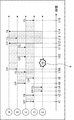
- FIG. 8 is a diagram for explaining a relationship with respect to a time axis between elements included in the monitoring target system 900.
- the horizontal axis represents the time axis.
- a to E are vertex identifiers, and a circle indicates an element represented by each vertex identifier.
- OP indicates that a certain process is opened from each element to another element
- CL indicates that the certain process is closed. That is, a certain element and another element have a relationship from open to close.
- the element having the vertex identifier “C” (hereinafter referred to as the element (C)) is “t1” to “t2” and “t6” to “t15” with respect to the element (D). ”.
- the element (D) is related to the element (E) between “t3” and “t4”.
- the element (E) has a relationship with respect to the element (A) between “t12” and “t14”.
- the element (A) has a relationship with respect to the element (B) between “t8” and “t13”.
- the element (B) has a relationship with respect to the element (C) from “t5” to “t7” and from “t10” to “t11”.
- the relationship graph used in the information processing apparatus 102 has time information (first time information) as an edge attribute, as shown in FIG.
- the time information indicated as the attribute of each side includes the time when the first process is opened and the time when the last process is closed from one element to another.
- the side from the element (C) to the element (D) includes a time “t1” when the first process is opened and a time “t15” when the last process is closed.
- the time “t1” when the first process is opened and the time “t15” when the last process is closed are described as (t1, t15).
- the time when the first process between certain elements is opened is also referred to as t first
- the time when the last process is closed is also referred to as t last
- the attribute information of each side is represented as (t first , t last ).
- FIG. 10 is a functional block diagram illustrating an example of a functional configuration of the information processing apparatus 102 according to the present embodiment.
- the information processing apparatus 102 according to the present embodiment includes a reach range extraction unit 140 and a data acquisition unit 150.
- the information processing apparatus 102 according to the present embodiment replaces the reach range extracting unit 110 in the information processing apparatus 100 according to the first embodiment with the reach range extracting unit 140 and The data acquisition unit 150 is provided, and the common range extraction unit 120 is not provided.
- the data acquisition unit 150 includes a relationship graph representing a relationship between a plurality of elements included in the monitoring target system 900, and information indicating a position on the monitoring target system 900 where an abnormality has been detected.
- the position information indicating the position of is acquired from an external device (not shown).
- the data acquisition unit 150 may be configured to acquire the relationship graph and the position information from other means (not shown) in the information processing apparatus 102.
- the method for acquiring the relationship graph and the position information is not particularly limited.
- the relationship graph has time information as an edge attribute.
- the position information includes information (second time information) indicating the time when the abnormality is detected.
- the data acquisition unit 150 is a function included in the reach range extraction unit 110 or the reach range extraction unit 130 described above.
- the data acquisition unit 150 supplies the acquired relationship graph and the position information to the reach range extraction unit 140.
- the reach range extraction unit 140 receives the relation graph and the position information from the data acquisition unit 150. Based on the time when the abnormality included in the position information is detected, the reach range extracting unit 140 starts from the position on the relation graph indicated by the position information including the information indicating the time, and starts from the position. The upper route (reach range) is extracted.
- the operation of the reach range extraction unit 140 in the information processing apparatus 102 will be described more specifically.
- the reach range extraction unit 140 receives the relationship graph as shown in FIG. 9 and the position information indicating the element (E) including the time “t9”.
- the time “t9” is a time after t8 and a time before t10 as shown by a star-shaped heptagon (position indicated by reference numeral 9) in FIG.
- the reach range extraction unit 140 performs a backward search and a forward search from the position, starting from the position on the relation graph of the element (E) at the time t9 indicated by the position information.
- a side between elements is described as, for example, a side (D, E).
- the first element in parentheses indicates the vertex identifier of the element at the starting point of the directed arrow
- the second element indicates the vertex identifier of the element at the end point of the directed arrow.
- the reach range extraction unit 140 first obtains the oldest time (referred to as the minimum time) acquired at the present time.
- the oldest time acquired at the present time indicates the last time when the detected abnormality can be affected.
- the current minimum value is referred to as t min .
- the initial value is the time indicated by the position information. Therefore, the initial value of the minimum value (t min ) is t9.
- the attribute information of the side (D, E) is (t3, t4) as shown in FIG. Therefore, t first of the side (D, E) is t3. Since t3 ⁇ t9 is satisfied, the reach range extraction unit 140 determines that the element (D) has a relationship with the element (E), and sets the element (D) as a target for backward search.
- the reach range extraction unit 140 obtains the last time that the element (D) was able to influence the detected abnormality. That is, the reach range extraction unit 140 obtains a new minimum value (t min ) using MIN (t min , t last ).
- the reach range extraction unit 140 checks whether or not t first ⁇ t min is satisfied for the side (B, C). Since t5> t4 and the above condition is not satisfied, the reach range extraction unit 140 does not set the element (B) as a target for backward search. Thereby, the reach range extraction unit 140 ends the backward search.
- the reach range extraction unit 140 first obtains the newest time (referred to as the maximum time) acquired at the present time.
- the most recent time acquired at the present time indicates the first time when the detected abnormality can be affected.
- the current maximum value is referred to as tmax .
- the initial value is the time indicated by the position information. Therefore, the initial value of the maximum value (t max ) is t9.
- the attribute information of the side (E, A) is (t12, t14) as shown in FIG. Therefore, t last of side (E, A) is t14.
- the reach range extraction unit 140 determines that the element (E) has a relationship with the element (A), and sets the element (A) as a forward search target.
- the reach range extraction unit 140 obtains the first time that the element (A) was able to influence the detected abnormality. That is, the reach range extraction unit 140 obtains a new maximum value (t max ) using MAX (t max , t first ).
- the reach range extraction unit 140 checks whether or not t max ⁇ t last is satisfied for the side (B, C). Since t12> t11 and the above condition is not satisfied, the reach range extraction unit 140 does not consider the element (C) as a forward search target. Thereby, the reach range extraction unit 140 ends the forward search.
- the reach range extraction unit 140 extracts the path on the relation graph extracted by the forward search and the backward search as described above as the abnormal influence process for each position on the relation graph indicated by the position information.
- the reach range extraction part 140 demonstrated performing forward search after performing backward search, this invention is not limited to this.
- the reach range extraction unit 140 may perform a backward search and a forward search simultaneously, or may perform a backward search after the forward search.
- effect According to the information processing apparatus 102 according to the present embodiment, it is possible to extract an abnormal influence process more suitably. Further, by extracting the abnormal influence process using the time information, the information processing apparatus 102 can reduce the search time for the abnormal influence process.
- Patent Document 1 or 2 has a possibility that the specified abnormality range is insufficient or too wide.
- the technology described in Patent Document 1 or 2 does not consider the dependency on the service or device in which the abnormality is detected when the abnormality is detected. That is, in the techniques of Patent Documents 1 and 2, even if the entire system has a dependency relationship, a service or device that does not have a dependency relationship with respect to the service or device in which the abnormality is detected at the time when the abnormality is detected. May also be extracted as an abnormal influence process. Therefore, it is required to more appropriately specify the influence process of the abnormality.
- the information processing apparatus 102 can also solve the above problems.
- FIG. 11 is a diagram illustrating an example of a relationship graph used in the information processing apparatus 102 according to the present modification. Note that the information processing apparatus 102 according to this modification has the same functional configuration as the information processing apparatus 102 illustrated in FIG.
- time information is included as an edge attribute
- the present invention is not limited to this.
- the time information may be included as an element attribute.
- FIG. 11 shows that a plurality of vertices (A 1 , B 1 , C 1 , D 1 , E 1 ) are generated at time t0 (initial state). Each vertex is generated from another element when a certain process is opened. In other words, every time an element M enters a state in which another element N can be newly affected, a vertex M i representing a state at a certain point in M and a vertex N j representing a state at a certain point in N Vertices N j + 1 representing the new state of element N with directed edges from.
- i and j are natural numbers. For example, in FIG.
- the processing from element (C) to element (D) is open at time “t1”. Therefore, as shown in FIG. 11, the relationship graph includes vertices D 2 to the position of the time "t1”. Furthermore, the relationship graph includes sides (sides from C 1 to D 2 and sides from D 1 to D 2 ) indicating the relationship between the vertices.
- a vertex (C 3 ) and a vertex (D 4 ) are newly generated.
- the relationship graph illustrated in FIG. 11 includes a vertex (C 3 ) having information of time “t10”.
- the processing from the element (C) to the element (D) is continuously performed at the time “t10”. Therefore, the process from the element (C) to the element (D) may be affected by the process on the element (C) by the element (B). Therefore, the relationship graph shown in FIG. 11 includes the vertex (D 4 ) at the same time “t10” as the time when the vertex (C 3 ) is included.
- the reach range extraction unit 140 uses the position on the relationship graph indicated by the position information and time as a starting point to indicate a path on the relationship graph that reaches from the position as an abnormal condition. Extract as an influence process.
- the reach range extraction unit 140 performs a backward search from the position of the vertex (E 2 ) as a starting point.
- the route associated with the vertex (E 2 ) is a route (C 1 to D 2 , D 1 to D 2 , D 2 to E 2 , E 1 to E 2) represented by a thick dashed arrow in FIG. ). Therefore, the reach range extraction unit 140 extracts the route as a result of the backward search.
- the reach range extraction unit 140 performs a forward search from the position of the vertex starting from the vertex (E 2 ).
- the route associated with the vertex (E 2 ) is a route (route from E 2 to A 2 , A 2 to B 3 ) represented by a thick broken arrow in FIG. Accordingly, the reach range extraction unit 140 extracts the route as a result of the forward search.
- the reach range extraction unit 140 extracts the path on the relation graph extracted by the forward search and the backward search as described above as the abnormal influence process for each position on the relation graph indicated by the position information.
- the range search part 140 demonstrated performing forward search after performing backward search, this invention is not limited to this.
- the reach range extraction unit 140 may perform a backward search and a forward search simultaneously, or may perform a backward search after the forward search.
- the influence process of the abnormality is more preferably performed as in the third embodiment described above. Can be extracted. Therefore, similarly to the above-described second embodiment, it is possible to extract the abnormal influence process with fewer man-hours.
- FIG. 12 is a functional block diagram illustrating a functional configuration of the information processing apparatus 103 according to the present modification. Note that members having the same functions as the members included in the drawings described in the first to third embodiments are denoted by the same reference numerals, and detailed description thereof is omitted.
- the information processing apparatus 103 includes a common range extraction unit 120, a reach range extraction unit 140, and a data acquisition unit 150, as shown in FIG. As illustrated in FIG. 12, the information processing apparatus 103 according to the present modification is configured to further include a common range extraction unit 120 in the information processing apparatus 102 described in the third embodiment.
- the reach range extraction unit 140 in the information processing device 103 for each position on the relation graph indicated by the position information, extracts the path on the relation graph extracted by the forward search and the backward search described in the third embodiment. Extract as reachable range. Then, the extracted reachable range is supplied to the common range extracting unit 120 for each of the plurality of positions on the relationship graph where the abnormality is detected.
- the common range extraction unit 120 uses the reach range extracted by the reach range extraction unit 140 for each of a plurality of positions on the relationship graph, A common range is extracted from a predetermined number of reachable ranges or more.
- the common range extraction unit 120 can extract the extracted range as an abnormal influence process.
- FIG. 13 is a functional block diagram illustrating an example of a functional configuration of the information processing apparatus 104 according to the present embodiment.
- the information processing apparatus 104 includes a reach range extraction unit 110, a common range extraction unit 120, and a path abnormality degree evaluation unit 160.
- the information processing apparatus 104 illustrated in FIG. 13 is configured to further include a path abnormality degree evaluation unit 160 in the information processing apparatus 100 of the first embodiment, but the path to the information processing apparatuses of other embodiments.
- the structure provided with the abnormality degree evaluation part 160 may be sufficient.
- the path abnormality degree evaluation unit 160 receives a relationship graph representing a relationship between a plurality of elements included in the monitoring target system 900 from an external device (not shown).
- the path abnormality degree evaluation unit 160 may be configured to acquire the relationship graph from other means (not shown) in the information processing apparatus 104.
- the method for acquiring the relationship graph is not particularly limited.
- the relationship graph acquired by the path abnormality degree evaluation unit 160 includes an edge abnormality degree (for example, weight) as an edge attribute. For example, when elements that are not related in normal operation are connected by an edge on the acquired relation graph, the edge includes a high degree of abnormality as an attribute of the edge. In addition, a side connecting elements having a relationship in a normal operation includes a low degree of abnormality as an attribute of the side.
- the path abnormality degree evaluation unit 160 acquires a relation graph including such edge attributes. Also, the degree of abnormality is not limited to a side, and may be given to a node.
- the path abnormality degree evaluation unit 160 acquires information indicating the position on the monitoring target system 900 where the abnormality is detected and indicating the position on the relation graph.
- the path abnormality degree evaluation unit 160 evaluates the degree of abnormality of the path from the acquired relation graph and the position information with respect to the path starting from the position on the relation graph indicated by the position information.
- the route abnormality degree evaluation unit 160 generates information indicating the degree of abnormality of the route, which is an evaluation result (evaluation result), and supplies the information to the reach range extraction unit 110.
- the path abnormality degree evaluation unit 160 may be configured to acquire the edge abnormality degree separately from the relationship graph.
- the path abnormality degree evaluation unit 160 may be configured to calculate an abnormality degree of each side for each side. For example, the path abnormality degree evaluation unit 160 obtains the sum of the distances of the respective sides, sets a threshold obtained by dividing the sum of the distances of the respective sides by the total number of the sides, and has a higher degree of abnormality for the side longer than the threshold. The side with a short distance is evaluated as having a low degree of abnormality.
- the threshold value may be a predetermined value.
- the path abnormality degree evaluation unit 160 may evaluate the degree of abnormality of each side by determining whether the number of occurrences of the relationship between elements represented by each side is smaller than a predetermined threshold.
- the threshold may be a number obtained by dividing the total number of times by the total number of sides.
- the path abnormality degree evaluation unit 160 supplies information (evaluation results) for making the search by the reach range extraction unit 110 more efficient to the reach range extraction unit 110.
- the arrival range extraction unit 110 extracts the arrival route using the evaluation result supplied from the route abnormality degree evaluation unit 160, the acquired relation graph, and the acquired position information. At this time, the reach range extraction unit 110 extracts a route having a high degree of abnormality as the reach range based on the evaluation result. For example, the reach range extraction unit 110 can extract the reach range by accumulating the degree of abnormality of each side in the route on the relationship graph from the position on the relationship graph indicated by the position information. A method of extracting a higher route may be used, or another method may be used. For example, the reach range extraction unit 110 may obtain an average value of the degree of abnormality and extract a route having a side having a degree of abnormality higher than the average value.
- the reach range extraction unit 110 supplies the extracted reach range to the common range extraction unit 120.
- the reachable range extracting unit 110 may supply the evaluation result acquired from the path abnormality degree evaluating unit 160 to the common range extracting unit 120.
- the common range extraction unit 120 may extract the common range using the evaluation result supplied from the reach range extraction unit 110 and the reach range. Thereby, the common range extraction unit 120 can extract the influence process reflecting the degree of abnormality. The common range extraction unit 120 may output the supplied evaluation result together with the extracted influence process.
- the reach range extraction unit 110 extracts the reach range using the evaluation result, it is possible to extract a reach range within a more suitable range.
- the common range extraction unit 120 extracts the influence process of the abnormality using the above evaluation result, the influence process reflecting the degree of the abnormality can be extracted more.
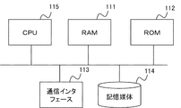
- the configuration shown in FIG. 14 includes a RAM (Random Access Memory) 111, a ROM (Read Only Memory) 112, a communication interface 113, a storage medium 114, and a CPU (Central Processing Unit) 115.
- the CPU 115 controls the overall operation of the information processing apparatus by reading various software programs (computer programs) stored in the ROM 112 or the storage medium 114 into the RAM 111 and executing them.
- the CPU 115 executes a software program that executes each function (each unit) included in the information processing apparatus while appropriately referring to the ROM 112 or the storage medium 114.
- the CPU 115 reads the computer program into the RAM 111 and executes the computer program. Achieved by:
- the supplied computer program may be stored in a computer-readable storage device such as a readable / writable memory (temporary storage medium) or a hard disk device.
- a computer-readable storage device such as a readable / writable memory (temporary storage medium) or a hard disk device.
- the present invention can be understood as being configured by a code representing the computer program or a storage medium storing the computer program.
Landscapes
- Engineering & Computer Science (AREA)
- General Engineering & Computer Science (AREA)
- Theoretical Computer Science (AREA)
- Computer Networks & Wireless Communication (AREA)
- Signal Processing (AREA)
- Computer Hardware Design (AREA)
- Computer Security & Cryptography (AREA)
- Physics & Mathematics (AREA)
- Quality & Reliability (AREA)
- General Physics & Mathematics (AREA)
- Computing Systems (AREA)
- Life Sciences & Earth Sciences (AREA)
- Bioinformatics & Cheminformatics (AREA)
- Bioinformatics & Computational Biology (AREA)
- Evolutionary Biology (AREA)
- Debugging And Monitoring (AREA)
- Data Exchanges In Wide-Area Networks (AREA)
Abstract
Description
本発明の第1の実施の形態について、図面を参照して詳細に説明する。図1は、本発明の第1の実施の形態に係る情報処理装置100の構成の一例を示す図である。図1に示す通り、情報処理装置100は、到達範囲抽出部110と、共通範囲抽出部120とを備えている。
到達範囲抽出部110は、監視対象システム900に含まれる複数のノード(要素とも呼ばれる)間の関係を表す関係グラフと、当該関係グラフ上の複数の位置を示す情報(位置情報)とを、図示しない外部装置から受信する。この位置情報は、異常が検知された監視対象システム900上の位置を示す情報である。なお、到達範囲抽出部110は、上記関係グラフと、上記位置情報とを、情報処理装置100内の図示しない他の手段から取得する構成であってもよい。上記関係グラフおよび上記位置情報を取得する方法は、特に限定されない。
共通範囲抽出部120は、到達範囲抽出部110から、異常が検知された関係グラフ上の位置ごとに抽出した関係グラフ上の経路を受け取る。そして、共通範囲抽出部120は、抽出された関係グラフ上の複数の経路のうち、所定数以上の経路で共通する範囲を抽出する。なお、抽出される共通範囲は、要素であってもよいし、辺であってもよいし、これらの集合であってもよい。そして、共通範囲抽出部120は、抽出される共通範囲から、異常の影響過程を抽出する。また、所定数以上の経路とは、全ての経路であってもよいし、予め定められた数または割合以上の経路であってもよい。
本実施の形態に係る情報処理装置100によれば、複数箇所で異常が発見された場合であっても、より好適に異常の影響過程を抽出することができる。
本実施の形態に係る情報処理装置100は、異常が検知された関係グラフ上の複数の位置(図5ではC1、C2)から、バックトレースを行うことにより、異常が検知された位置から到達する到達範囲を抽出することを例に説明を行ったが、本発明はこれに限定されるものではない。情報処理装置100の到達範囲抽出部110は、異常が検知された位置から、フォワードトレースを行うことにより、到達範囲を抽出してもよい。ここで、フォワードトレースとは、関係グラフが有向グラフである場合に、有向辺を正方向に辿ることである。以降、フォワードトレースを前方検索とも呼ぶ。
本発明の第2の実施の形態について、図面を参照して詳細に説明する。なお、上述した第1の実施の形態で説明した図面に含まれる部材と同じ機能を有する部材については、同じ符号を付し、その詳細な説明を省略する。
到達範囲抽出部130は、監視対象システム900に含まれる複数の要素間の関係を表す関係グラフと、異常が検出された監視対象システム900上の位置を示す情報であって、当該関係グラフ上の複数の位置を示す位置情報とを、図示しない外部装置から受信する。
本実施の形態に係る情報処理装置101によれば、複数箇所で異常が発見された場合であっても、より好適に異常の影響過程を抽出することができる。
(1)異常の発生が検知されたシステム上の位置を示す情報であって、関係グラフ上の位置を示す1または複数の第1の位置情報で示される位置。
(2)異常の原因の可能性があるとして検知された関係グラフ上の1または複数の位置を示す第2の位置情報で示される位置。
本発明の第3の実施の形態について、図面を参照して詳細に説明する。なお、上述した第1および第2の実施の形態で説明した図面に含まれる部材と同じ機能を有する部材については、同じ符号を付し、その詳細な説明を省略する。
本実施の形態に係る情報処理装置102によれば、より好適に異常の影響過程を抽出することができる。また、時間情報を用いて異常の影響過程の抽出を行うことにより、情報処理装置102は、異常の影響過程の探索時間を削減することができる。
本実施の形態に係る変形例1について、図11を参照して説明を行う。図11は、本変形例に係る情報処理装置102で使用する関係グラフの一例を示す図である。なお、本変形例に係る情報処理装置102は、図10に示す情報処理装置102と同様の機能構成を有するため、その説明を省略する。
本実施の形態に係る変形例2について、図12を参照して説明を行う。図12は、本変形例に係る情報処理装置103の機能構成を示す機能ブロック図である。なお、上述した第1から第3の実施の形態で説明した図面に含まれる部材と同じ機能を有する部材については、同じ符号を付し、その詳細な説明を省略する。
本発明の第4の実施の形態について、図面を参照して詳細に説明する。なお、上述した第1から第3の実施の形態で説明した図面に含まれる部材と同じ機能を有する部材については、同じ符号を付し、その詳細な説明を省略する。
経路異常度評価部160は、監視対象システム900に含まれる複数の要素間の関係を表す関係グラフを、図示しない外部装置から受信する。なお、経路異常度評価部160は、上記関係グラフを、情報処理装置104内の図示しない他の手段から取得する構成であってもよい。上記関係グラフを取得する方法は、特に限定されない。
本実施の形態に係る情報処理装置104によれば、より好適に異常の影響過程を抽出することができる。なぜならば、経路異常度評価部160が、関係グラフの経路の異常度を評価し、評価結果を生成するからである。
なお、図1、6、10、12および13に示した情報処理装置の各部は、図14に例示するハードウェア資源で実現してもよい。即ち、図14に示す構成は、RAM(Random Access Memory)111、ROM(Read Only Memory)112、通信インタフェース113、記憶媒体114およびCPU(Central Processing Unit)115を備える。CPU115は、ROM112または記憶媒体114に記憶された各種ソフトウェアプログラム(コンピュータプログラム)を、RAM111に読み出して実行することにより、情報処理装置の全体的な動作を司る。すなわち、上記各実施形態において、CPU115は、ROM112または記憶媒体114を適宜参照しながら、情報処理装置が備える各機能(各部)を実行するソフトウェアプログラムを実行する。
100 情報処理装置
101 情報処理装置
102 情報処理装置
103 情報処理装置
104 情報処理装置
110 到達範囲抽出部
120 共通範囲抽出部
130 到達範囲抽出部
131 第1の抽出部
132 第2の抽出部
140 到達範囲抽出部
150 データ取得部
160 経路異常度評価部
900 監視対象システム
920 要素
Claims (21)
- システムに含まれる複数の要素間の関係を表す関係グラフ、および、異常が検知された前記システム上の位置を示す情報であって、当該関係グラフ上の複数の位置を示す位置情報を用いて、前記複数の位置の夫々を起点に、当該位置から直接的または間接的に関係を有する前記要素の集合からなる前記関係グラフ上の経路を、到達範囲として抽出する到達範囲抽出手段と、
前記到達範囲として抽出された前記関係グラフ上の複数の経路のうち、所定数以上の経路で共通する範囲を抽出することにより、異常の影響過程を抽出する共通範囲抽出手段と、を備えることを特徴とする情報処理装置。 - 前記位置情報には、異常の発生が検知された前記システム上の位置を示す情報であって、前記関係グラフ上の位置を示す複数の第1の位置情報が含まれ、
前記到達範囲抽出手段は、前記複数の第1の位置情報の夫々で示される関係グラフ上の位置から、到達範囲を抽出する、ことを特徴とする請求項1に記載の情報処理装置。 - 前記位置情報には、異常の発生が検知された前記システム上の位置を示す情報であって、前記関係グラフ上の位置を示す1または複数の第1の位置情報と、異常の原因の可能性があるとして検知された関係グラフ上の1または複数の位置を示す第2の位置情報とが含まれ、
前記到達範囲抽出手段は、前記第1の位置情報によって示される、前記関係グラフ上の位置を起点に、当該位置から直接的または間接的に関係を有する前記要素の集合からなる前記関係グラフ上の経路を、第1の到達範囲として抽出する第1の抽出手段と、前記第2の位置情報によって示される、前記関係グラフ上の位置を起点に、当該位置から直接的または間接的に関係を有する前記要素の集合からなる前記関係グラフ上の経路を、第2の到達範囲として抽出する第2の抽出手段とを含み、
前記共通範囲抽出手段は、前記第1の位置情報によって示される、前記関係グラフ上の位置と、前記第2の位置情報によって示される、前記関係グラフ上の位置との間の経路を、前記異常の影響過程として抽出することを特徴とする請求項1に記載の情報処理装置。 - 前記関係グラフには、前記要素および/または前記辺の属性として、第1の時間情報が含まれ、
前記位置情報には、前記異常が検知された時間を示す第2の時間情報が含まれ、
前記到達範囲抽出手段は、前記第2の時間情報によって示される、前記異常が検知された時間に基づいて、当該第2の時間情報を含む前記位置情報によって示される、前記関係グラフ上の位置を起点に、当該位置から到達する前記関係グラフ上の経路を、前記到達範囲として抽出する、ことを特徴とする請求項1から3の何れか1項に記載の情報処理装置。 - 前記第1の時間情報が前記要素の属性であるとき、前記到達範囲抽出手段は、前記異常が検知された時間より前の時間を検索する第1の検索、および/または、前記異常が検知された時間より後の時間を検索する第2の検索を行うことにより、前記位置情報によって示される前記関係グラフ上の位置から到達する前記関係グラフ上の経路を抽出する、ことを特徴とする請求項4に記載の情報処理装置。
- 前記第1の時間情報には、各辺に対し、前記辺の一方の端部に接続された要素から他方の端部に接続された要素に対し、最初に影響を及ぼした開始時間と、最後に影響を及ぼした終了時間とが含まれ、
前記第1の検索は、現時点で取得可能な最も古い時間と前記終了時間とを比較し、古い方の時間を前記最も古い時間とし、前記開始時間が当該最も古い時間より前の時間の場合、当該開始時間を含む辺の前記一方の端部に接続された前記要素を前記到達範囲に含ませ、前記開始時間が前記最も古い時間より後の時間の場合、前記開始時間を含む辺の前記一方の端部に接続された前記要素を前記到達範囲に含ませない、ことを特徴とする請求項5に記載の情報処理装置。 - 前記第1の時間情報には、各辺に対し、前記辺の一方の端部に接続された要素から他方の端部に接続された要素に対し、最初に影響を及ぼした開始時間と、最後に影響を及ぼした終了時間とが含まれ、
前記第2の検索は、現時点で取得可能な最も新しい時間と前記開始時間とを比較し、新しい方の時間を前記最も新しい時間とし、前記終了時間が当該最も新しい時間より後の時間の場合、当該終了時間を含む辺の前記他方の端部に接続された前記要素を前記到達範囲に含ませ、前記終了時間が当該最も新しい時間より前の時間の場合、前記終了時間を含む辺の前記他方の端部に接続された前記要素を前記到達範囲に含ませない、ことを特徴とする請求項5または6に記載の情報処理装置。 - 前記関係グラフには、ある要素が他の要素に影響を与えることができる状態になるたびに生成される、第1の時間情報を含む頂点が含まれ、
前記位置情報には、前記異常が検知された時間を示す第2の時間情報が含まれ、
前記到達範囲抽出手段は、前記第2の時間情報によって示される、前記異常が検知された時間に基づいて、前記第2の時間情報を含む前記位置情報によって示される、前記関係グラフ上の位置を起点に、当該位置から到達する前記関係グラフ上の経路を、前記到達範囲として抽出する、ことを特徴とする請求項1から3の何れか1項に記載の情報処理装置。 - 前記関係グラフの経路の異常度を評価し、評価結果を生成する、経路異常度評価手段を更に備え、
前記到達範囲抽出手段は、前記評価結果を用いて、前記到達範囲を抽出する、ことを特徴とする請求項1から8の何れか1項に記載の情報処理装置。 - 前記共通範囲抽出手段は、前記評価結果を用いて、前記異常の影響過程を抽出する、ことを特徴とする請求項9に記載の情報処理装置。
- システムに含まれる複数の要素間の関係を表す関係グラフ、および、異常が検出された前記システム上の位置を示す情報であって、当該関係グラフ上の位置を示す位置情報を取得する取得手段と、
当該取得手段が取得した前記関係グラフおよび前記位置情報を用いて、前記位置を起点に、当該位置から直接的または間接的に関係を有する前記要素の集合からなる前記関係グラフ上の経路を、異常の影響過程として抽出する到達範囲抽出手段と、を備えることを特徴とする情報処理装置。 - 前記関係グラフには、前記要素および/または前記辺の属性として、第1の時間情報が含まれ、
前記位置情報には、前記異常が検知された時間を示す第2の時間情報が含まれ、
前記到達範囲抽出手段は、前記第2の時間情報によって示される、異常が検知された時間に基づいて、当該第2の時間情報を含む前記位置情報によって示される前記関係グラフ上の位置を起点に、当該位置から到達する前記関係グラフ上の経路を、前記異常の影響過程として特定する、ことを特徴とする請求項11に記載の情報処理装置。 - 前記第1の時間情報が前記要素の属性であるとき、前記到達範囲抽出手段は、前記異常が検知された時間より前の時間を検索する第1の検索、および/または、前記異常が検知された時間より後の時間を検索する第2の検索を行うことにより、前記位置情報によって示される前記関係グラフ上の位置から到達する前記関係グラフ上の経路を抽出する、ことを特徴とする請求項12に記載の情報処理装置。
- 前記第1の時間情報には、各辺に対し、前記辺の一方の端部に接続された要素から他方の端部に接続された要素に対し、最初に影響を及ぼした開始時間と、最後に影響を及ぼした終了時間とが含まれ、
前記第1の検索は、現時点で取得可能な最も古い時間と前記終了時間とを比較し、古い方の時間を前記最も古い時間とし、前記開始時間が当該最も古い時間より前の時間の場合、当該開始時間を含む辺の前記一方の端部に接続された前記要素を前記異常の影響過程に含ませ、前記開始時間が前記最も古い時間より後の時間の場合、前記開始時間を含む辺の前記一方の端部に接続された前記要素を前記異常の影響過程に含ませない、ことを特徴とする請求項13に記載の情報処理装置。 - 前記第1の時間情報には、各辺に対し、前記辺の一方の端部に接続された要素から他方の端部に接続された要素に対し、最初に影響を及ぼした開始時間と、最後に影響を及ぼした終了時間とが含まれ、
前記第2の検索は、現時点で取得可能な最も新しい時間と前記開始時間とを比較し、新しい方の時間を前記最も新しい時間とし、前記終了時間が当該最も新しい時間より後の時間の場合、当該終了時間を含む辺の前記他方の端部に接続された前記要素を前記異常の影響過程に含ませ、前記終了時間が当該最も新しい時間より前の時間の場合、前記終了時間を含む辺の前記他方の端部に接続された前記要素を前記異常の影響過程に含ませない、ことを特徴とする請求項13または14に記載の情報処理装置。 - 前記関係グラフには、ある要素が他の要素に影響を与えることができる状態になるたびに生成される、第1の時間情報を含む頂点が含まれ、
前記位置情報には、前記異常が検知された時間を示す第2の時間情報が含まれ、
前記到達範囲抽出手段は、前記第2の時間情報によって示される、前記異常が検知された時間に基づいて、前記第2の時間情報を含む前記位置情報によって示される、前記関係グラフ上の位置を起点に、当該位置から到達する前記関係グラフ上の経路を、前記異常の影響過程として抽出する、ことを特徴とする請求項11に記載の情報処理装置。 - 前記関係グラフの経路の異常度を評価し、評価結果を生成する、経路異常度評価手段を更に備え、
前記到達範囲抽出手段は、前記評価結果を用いて、前記異常の影響過程を抽出する、ことを特徴とする請求項11から16の何れか1項に記載の情報処理装置。 - 情報処理装置の影響過程抽出方法であって、
システムに含まれる複数の要素間の関係を表す関係グラフ、および、異常が検知された前記システム上の位置を示す情報であって、当該関係グラフ上の複数の位置を示す位置情報を用いて、前記複数の位置の夫々を起点に、当該位置から直接的または間接的に関係を有する前記要素の集合からなる前記関係グラフ上の経路を、到達範囲として抽出し、
前記到達範囲として抽出された前記関係グラフ上の複数の経路のうち、所定数以上の経路で共通する範囲を抽出することにより、異常の影響過程を抽出する、ことを特徴とする影響過程抽出方法。 - 情報処理装置の影響過程抽出方法であって、
システムに含まれる複数の要素間の関係を表す関係グラフ、および、異常が検出された前記システム上の位置を示す情報であって、当該関係グラフ上の位置を示す位置情報を取得し、
前記取得した前記関係グラフおよび前記位置情報を用いて、前記位置を起点に、当該位置から直接的または間接的に関係を有する前記要素の集合からなる前記関係グラフ上の経路を、異常の影響過程として抽出する、ことを特徴とする影響過程抽出方法。 - 情報処理装置を含むコンピュータに、
システムに含まれる複数の要素間の関係を表す関係グラフ、および、異常が検知された前記システム上の位置を示す情報であって、当該関係グラフ上の複数の位置を示す位置情報を用いて、前記複数の位置の夫々を起点に、当該位置から直接的または間接的に関係を有する前記要素の集合からなる前記関係グラフ上の経路を、到達範囲として抽出する処理と、
前記到達範囲として抽出された前記関係グラフ上の複数の経路のうち、所定数以上の経路で共通する範囲を抽出することにより、異常の影響過程を抽出する処理と、を実行させるプログラムを記録するコンピュータで読み取り可能な記録媒体。 - 情報処理装置を含むコンピュータに、
システムに含まれる複数の要素間の関係を表す関係グラフ、および、異常が検出された前記システム上の位置を示す情報であって、当該関係グラフ上の位置を示す位置情報を取得する処理と、
前記取得した前記関係グラフおよび前記位置情報を用いて、前記位置を起点に、当該位置から直接的または間接的に関係を有する前記要素の集合からなる前記関係グラフ上の経路を、異常の影響過程として抽出する処理と、を実行させるプログラムを記録するコンピュータで読み取り可能な記録媒体。
Priority Applications (3)
| Application Number | Priority Date | Filing Date | Title |
|---|---|---|---|
| US15/126,920 US10887331B2 (en) | 2014-03-20 | 2014-06-17 | Information processing apparatus and influence-process extraction method |
| JP2016508307A JP6288244B2 (ja) | 2014-03-20 | 2014-06-17 | 情報処理装置、影響過程抽出方法およびプログラム |
| EP14886257.6A EP3121723A4 (en) | 2014-03-20 | 2014-06-17 | Information processing device, influence-process extraction method, and recording medium |
Applications Claiming Priority (2)
| Application Number | Priority Date | Filing Date | Title |
|---|---|---|---|
| JP2014058558 | 2014-03-20 | ||
| JP2014-058558 | 2014-03-20 |
Publications (1)
| Publication Number | Publication Date |
|---|---|
| WO2015140843A1 true WO2015140843A1 (ja) | 2015-09-24 |
Family
ID=54143869
Family Applications (1)
| Application Number | Title | Priority Date | Filing Date |
|---|---|---|---|
| PCT/JP2014/003227 Ceased WO2015140843A1 (ja) | 2014-03-20 | 2014-06-17 | 情報処理装置、影響過程抽出方法および記録媒体 |
Country Status (4)
| Country | Link |
|---|---|
| US (1) | US10887331B2 (ja) |
| EP (1) | EP3121723A4 (ja) |
| JP (1) | JP6288244B2 (ja) |
| WO (1) | WO2015140843A1 (ja) |
Cited By (6)
| Publication number | Priority date | Publication date | Assignee | Title |
|---|---|---|---|---|
| WO2017094820A1 (ja) * | 2015-12-02 | 2017-06-08 | 日本電気株式会社 | 支援装置、支援方法および記録媒体 |
| JP2018205811A (ja) * | 2017-05-30 | 2018-12-27 | 富士通株式会社 | 影響範囲特定プログラム、影響範囲特定方法、および影響範囲特定装置 |
| WO2019031473A1 (ja) * | 2017-08-09 | 2019-02-14 | 日本電気株式会社 | 情報選択装置、情報選択方法、及び、情報選択プログラムが記録された記録媒体 |
| US10909014B2 (en) | 2017-02-22 | 2021-02-02 | Nec Corporation | Information processing device, information processing system, monitoring method, and recording medium |
| WO2021186683A1 (ja) * | 2020-03-19 | 2021-09-23 | 三菱電機株式会社 | 汚染範囲特定装置および汚染範囲特定プログラム |
| JPWO2022264317A1 (ja) * | 2021-06-16 | 2022-12-22 |
Families Citing this family (18)
| Publication number | Priority date | Publication date | Assignee | Title |
|---|---|---|---|---|
| WO2016060067A1 (ja) * | 2014-10-14 | 2016-04-21 | 日本電信電話株式会社 | 特定装置、特定方法および特定プログラム |
| US12206708B2 (en) * | 2015-10-28 | 2025-01-21 | Qomplx Llc | Correlating network event anomalies using active and passive external reconnaissance to identify attack information |
| US10289471B2 (en) * | 2016-02-08 | 2019-05-14 | Nec Corporation | Ranking causal anomalies via temporal and dynamical analysis on vanishing correlations |
| US9967267B2 (en) | 2016-04-15 | 2018-05-08 | Sophos Limited | Forensic analysis of computing activity |
| US12153674B2 (en) | 2016-04-15 | 2024-11-26 | Sophos Limited | Tracking malware root causes with an event graph |
| US10129274B2 (en) * | 2016-09-22 | 2018-11-13 | Adobe Systems Incorporated | Identifying significant anomalous segments of a metrics dataset |
| US11297073B2 (en) | 2018-08-31 | 2022-04-05 | Sophos Limited | Forensic query of local event streams in an enterprise network |
| US11792210B2 (en) | 2019-08-02 | 2023-10-17 | Crowdstrike, Inc. | Mapping unbounded incident scores to a fixed range |
| US11516237B2 (en) * | 2019-08-02 | 2022-11-29 | Crowdstrike, Inc. | Visualization and control of remotely monitored hosts |
| US11582246B2 (en) | 2019-08-02 | 2023-02-14 | Crowd Strike, Inc. | Advanced incident scoring |
| US11588832B2 (en) | 2019-08-02 | 2023-02-21 | Crowdstrike, Inc. | Malicious incident visualization |
| US12204870B2 (en) | 2022-03-31 | 2025-01-21 | Sophos Limited | Natural language analysis of a command line using a machine learning model to generate a natural language description of the command line |
| US12130923B2 (en) | 2022-03-31 | 2024-10-29 | Sophos Limited | Methods and apparatus for augmenting training data using large language models |
| US12265526B2 (en) | 2022-03-31 | 2025-04-01 | Sophos Limited | Methods and apparatus for natural language interface for constructing complex database queries |
| US12526289B2 (en) | 2022-05-17 | 2026-01-13 | Sophos Limited | Methods and apparatus for machine learning to generate a decision tree database to identify commands similar to a command of interest |
| US12287700B2 (en) * | 2023-04-06 | 2025-04-29 | Sap Se | Systems and methods for predictive memory maintenance visualization |
| US12511180B2 (en) | 2023-04-27 | 2025-12-30 | Sap Se | Systems and methods for predictive memory maintenance |
| US12277029B2 (en) | 2023-04-27 | 2025-04-15 | Sap Se | Systems and methods for predictive memory maintenance |
Citations (6)
| Publication number | Priority date | Publication date | Assignee | Title |
|---|---|---|---|---|
| JPH06175884A (ja) * | 1992-12-04 | 1994-06-24 | Nippon Telegr & Teleph Corp <Ntt> | プログラムエラー原因究明装置 |
| JPH11259331A (ja) * | 1998-03-13 | 1999-09-24 | Nippon Telegr & Teleph Corp <Ntt> | ネットワークにおける障害箇所検出方法及び装置及びネットワークにおける障害箇所検出プログラムを格納した記憶媒体 |
| JP2011113571A (ja) * | 2009-11-27 | 2011-06-09 | Korea Electronics Telecommun | 資源間の物理的/論理的な関係をマッピングする方法及び装置 |
| JP2011113122A (ja) * | 2009-11-24 | 2011-06-09 | Mitsubishi Electric Corp | 障害影響分析装置及び業務システム及び障害影響分析方法 |
| WO2012073686A1 (ja) * | 2010-11-30 | 2012-06-07 | 独立行政法人科学技術振興機構 | ディペンダビリティ維持装置、ディペンダビリティ維持システム、障害対応システム、ディペンダビリティ維持装置の制御方法、制御プログラムおよびそれを記録したコンピュータ読み取り可能な記録媒体 |
| US20120215912A1 (en) * | 2011-02-17 | 2012-08-23 | Zenoss, Inc. | Method and apparatus for event correlation related to service impact analysis in a virtualized environment |
Family Cites Families (9)
| Publication number | Priority date | Publication date | Assignee | Title |
|---|---|---|---|---|
| US20020061001A1 (en) * | 2000-08-25 | 2002-05-23 | The Regents Of The University Of California | Dynamic source tracing (DST) routing protocol for wireless networks |
| WO2004112327A1 (ja) * | 2003-06-11 | 2004-12-23 | Nec Corporation | ルータ装置およびネットワーク接続方式 |
| US7183923B2 (en) * | 2004-02-20 | 2007-02-27 | Hitachi, Ltd. | Traceability system |
| EP2033113A2 (en) * | 2006-05-26 | 2009-03-11 | Whaleback Systems Corporation | Selecting routes through a network |
| JP5264470B2 (ja) | 2008-12-26 | 2013-08-14 | 三菱電機株式会社 | 攻撃判定装置及びプログラム |
| US8392760B2 (en) * | 2009-10-14 | 2013-03-05 | Microsoft Corporation | Diagnosing abnormalities without application-specific knowledge |
| EP2613480A4 (en) * | 2010-08-30 | 2015-05-27 | Nec Corp | COMMUNICATION QUALITY MONITORING SYSTEM, COMMUNICATION QUALITY MONITORING METHOD AND MEMORY MEDIUM |
| US8751867B2 (en) * | 2011-10-12 | 2014-06-10 | Vmware, Inc. | Method and apparatus for root cause and critical pattern prediction using virtual directed graphs |
| US20130103739A1 (en) * | 2011-10-21 | 2013-04-25 | Cisco Technology, Inc. | Obtaining Dynamic Connected-Network Topology Via any Node in Network |
-
2014
- 2014-06-17 US US15/126,920 patent/US10887331B2/en active Active
- 2014-06-17 EP EP14886257.6A patent/EP3121723A4/en not_active Withdrawn
- 2014-06-17 JP JP2016508307A patent/JP6288244B2/ja active Active
- 2014-06-17 WO PCT/JP2014/003227 patent/WO2015140843A1/ja not_active Ceased
Patent Citations (6)
| Publication number | Priority date | Publication date | Assignee | Title |
|---|---|---|---|---|
| JPH06175884A (ja) * | 1992-12-04 | 1994-06-24 | Nippon Telegr & Teleph Corp <Ntt> | プログラムエラー原因究明装置 |
| JPH11259331A (ja) * | 1998-03-13 | 1999-09-24 | Nippon Telegr & Teleph Corp <Ntt> | ネットワークにおける障害箇所検出方法及び装置及びネットワークにおける障害箇所検出プログラムを格納した記憶媒体 |
| JP2011113122A (ja) * | 2009-11-24 | 2011-06-09 | Mitsubishi Electric Corp | 障害影響分析装置及び業務システム及び障害影響分析方法 |
| JP2011113571A (ja) * | 2009-11-27 | 2011-06-09 | Korea Electronics Telecommun | 資源間の物理的/論理的な関係をマッピングする方法及び装置 |
| WO2012073686A1 (ja) * | 2010-11-30 | 2012-06-07 | 独立行政法人科学技術振興機構 | ディペンダビリティ維持装置、ディペンダビリティ維持システム、障害対応システム、ディペンダビリティ維持装置の制御方法、制御プログラムおよびそれを記録したコンピュータ読み取り可能な記録媒体 |
| US20120215912A1 (en) * | 2011-02-17 | 2012-08-23 | Zenoss, Inc. | Method and apparatus for event correlation related to service impact analysis in a virtualized environment |
Non-Patent Citations (1)
| Title |
|---|
| See also references of EP3121723A4 * |
Cited By (13)
| Publication number | Priority date | Publication date | Assignee | Title |
|---|---|---|---|---|
| WO2017094820A1 (ja) * | 2015-12-02 | 2017-06-08 | 日本電気株式会社 | 支援装置、支援方法および記録媒体 |
| JPWO2017094820A1 (ja) * | 2015-12-02 | 2018-10-04 | 日本電気株式会社 | 支援装置、支援方法およびプログラム |
| US11372839B2 (en) | 2015-12-02 | 2022-06-28 | Nec Corporation | Anomalous event confirmation assistance apparatus, anomalous event confirmation assistance meithod, and recording medium |
| US10909014B2 (en) | 2017-02-22 | 2021-02-02 | Nec Corporation | Information processing device, information processing system, monitoring method, and recording medium |
| US11914493B2 (en) | 2017-02-22 | 2024-02-27 | Nec Corporation | Information processing device, information processing system, monitoring method, and recording medium |
| JP2018205811A (ja) * | 2017-05-30 | 2018-12-27 | 富士通株式会社 | 影響範囲特定プログラム、影響範囲特定方法、および影響範囲特定装置 |
| JPWO2019031473A1 (ja) * | 2017-08-09 | 2020-07-16 | 日本電気株式会社 | 情報選択装置、情報選択方法、及び、情報選択プログラム |
| US20200244688A1 (en) * | 2017-08-09 | 2020-07-30 | Nec Corporation | Information selection device, information selection method, and non-transitory recording medium |
| WO2019031473A1 (ja) * | 2017-08-09 | 2019-02-14 | 日本電気株式会社 | 情報選択装置、情報選択方法、及び、情報選択プログラムが記録された記録媒体 |
| WO2021186683A1 (ja) * | 2020-03-19 | 2021-09-23 | 三菱電機株式会社 | 汚染範囲特定装置および汚染範囲特定プログラム |
| JP6987332B1 (ja) * | 2020-03-19 | 2021-12-22 | 三菱電機株式会社 | 汚染範囲特定装置および汚染範囲特定プログラム |
| JPWO2022264317A1 (ja) * | 2021-06-16 | 2022-12-22 | ||
| JP7679878B2 (ja) | 2021-06-16 | 2025-05-20 | 日本電気株式会社 | 情報可視化装置、情報可視化方法、及びプログラム |
Also Published As
| Publication number | Publication date |
|---|---|
| US10887331B2 (en) | 2021-01-05 |
| JPWO2015140843A1 (ja) | 2017-04-06 |
| US20170093900A1 (en) | 2017-03-30 |
| EP3121723A1 (en) | 2017-01-25 |
| JP6288244B2 (ja) | 2018-03-07 |
| EP3121723A4 (en) | 2017-11-22 |
Similar Documents
| Publication | Publication Date | Title |
|---|---|---|
| JP6288244B2 (ja) | 情報処理装置、影響過程抽出方法およびプログラム | |
| US10789118B2 (en) | Information processing device and error detection method | |
| CN109726066B (zh) | 用于标识存储系统中的问题部件的方法和设备 | |
| CN110995482A (zh) | 告警分析方法、装置、计算机设备及计算机可读存储介质 | |
| US9355005B2 (en) | Detection apparatus and detection method | |
| CN108573172B (zh) | 一种数据校验、存储方法及装置 | |
| CN107102929A (zh) | 故障的检测方法及装置 | |
| CN111625841A (zh) | 一种病毒处理方法、装置及设备 | |
| US10356010B2 (en) | Control device | |
| JP2015176230A (ja) | テストケース生成装置、方法、及びプログラム | |
| JP5836316B2 (ja) | 障害監視システム、障害監視方法、及び障害監視プログラム | |
| WO2015087509A1 (ja) | 状態保存復元装置、状態保存復元方法、および、記憶媒体 | |
| CN116361790A (zh) | 一种检测恶意软件活动的方法及装置 | |
| US20190050568A1 (en) | Process search apparatus and computer-readable recording medium | |
| CN104090838A (zh) | 一种生成测试用例的方法 | |
| JPWO2020065778A1 (ja) | 情報処理装置、制御方法、及びプログラム | |
| JP2016085152A (ja) | 診断装置、診断プログラム及び診断方法 | |
| US9690639B2 (en) | Failure detecting apparatus and failure detecting method using patterns indicating occurrences of failures | |
| JP5516192B2 (ja) | モデル作成装置、モデル作成プログラムおよびモデル作成方法 | |
| JP2021068097A (ja) | 脆弱性分析装置 | |
| JP6257236B2 (ja) | データ処理装置及びデータ処理方法及びプログラム | |
| CN112486940B (zh) | 用于事件排序的方法、设备和计算机程序产品 | |
| US20260094018A1 (en) | Generation method, computer-readable recording medium, and information processing device | |
| WO2015045091A1 (ja) | ベイジアンネットワークの構造学習におけるスーパーストラクチャ抽出のための方法及びプログラム | |
| JP7259436B2 (ja) | 情報処理装置、情報処理方法、情報処理プログラム、及び情報処理システム |
Legal Events
| Date | Code | Title | Description |
|---|---|---|---|
| 121 | Ep: the epo has been informed by wipo that ep was designated in this application |
Ref document number: 14886257 Country of ref document: EP Kind code of ref document: A1 |
|
| ENP | Entry into the national phase |
Ref document number: 2016508307 Country of ref document: JP Kind code of ref document: A |
|
| WWE | Wipo information: entry into national phase |
Ref document number: 15126920 Country of ref document: US |
|
| NENP | Non-entry into the national phase |
Ref country code: DE |
|
| REEP | Request for entry into the european phase |
Ref document number: 2014886257 Country of ref document: EP |
|
| WWE | Wipo information: entry into national phase |
Ref document number: 2014886257 Country of ref document: EP |