WO2015140880A1 - Compresseur et appareil à cycle de réfrigération - Google Patents
Compresseur et appareil à cycle de réfrigération Download PDFInfo
- Publication number
- WO2015140880A1 WO2015140880A1 PCT/JP2014/057040 JP2014057040W WO2015140880A1 WO 2015140880 A1 WO2015140880 A1 WO 2015140880A1 JP 2014057040 W JP2014057040 W JP 2014057040W WO 2015140880 A1 WO2015140880 A1 WO 2015140880A1
- Authority
- WO
- WIPO (PCT)
- Prior art keywords
- refrigerant
- compressor
- temperature
- compressor according
- pressure
- Prior art date
- Legal status (The legal status is an assumption and is not a legal conclusion. Google has not performed a legal analysis and makes no representation as to the accuracy of the status listed.)
- Ceased
Links
Images




Classifications
-
- F—MECHANICAL ENGINEERING; LIGHTING; HEATING; WEAPONS; BLASTING
- F25—REFRIGERATION OR COOLING; COMBINED HEATING AND REFRIGERATION SYSTEMS; HEAT PUMP SYSTEMS; MANUFACTURE OR STORAGE OF ICE; LIQUEFACTION SOLIDIFICATION OF GASES
- F25B—REFRIGERATION MACHINES, PLANTS OR SYSTEMS; COMBINED HEATING AND REFRIGERATION SYSTEMS; HEAT PUMP SYSTEMS
- F25B1/00—Compression machines, plants or systems with non-reversible cycle
- F25B1/04—Compression machines, plants or systems with non-reversible cycle with compressor of rotary type
-
- C—CHEMISTRY; METALLURGY
- C09—DYES; PAINTS; POLISHES; NATURAL RESINS; ADHESIVES; COMPOSITIONS NOT OTHERWISE PROVIDED FOR; APPLICATIONS OF MATERIALS NOT OTHERWISE PROVIDED FOR
- C09K—MATERIALS FOR MISCELLANEOUS APPLICATIONS, NOT PROVIDED FOR ELSEWHERE
- C09K5/00—Heat-transfer, heat-exchange or heat-storage materials, e.g. refrigerants; Materials for the production of heat or cold by chemical reactions other than by combustion
- C09K5/02—Materials undergoing a change of physical state when used
- C09K5/04—Materials undergoing a change of physical state when used the change of state being from liquid to vapour or vice versa
- C09K5/041—Materials undergoing a change of physical state when used the change of state being from liquid to vapour or vice versa for compression-type refrigeration systems
- C09K5/044—Materials undergoing a change of physical state when used the change of state being from liquid to vapour or vice versa for compression-type refrigeration systems comprising halogenated compounds
- C09K5/045—Materials undergoing a change of physical state when used the change of state being from liquid to vapour or vice versa for compression-type refrigeration systems comprising halogenated compounds containing only fluorine as halogen
-
- C—CHEMISTRY; METALLURGY
- C10—PETROLEUM, GAS OR COKE INDUSTRIES; TECHNICAL GASES CONTAINING CARBON MONOXIDE; FUELS; LUBRICANTS; PEAT
- C10M—LUBRICATING COMPOSITIONS; USE OF CHEMICAL SUBSTANCES EITHER ALONE OR AS LUBRICATING INGREDIENTS IN A LUBRICATING COMPOSITION
- C10M171/00—Lubricating compositions characterised by purely physical criteria, e.g. containing as base-material, thickener or additive, ingredients which are characterised exclusively by their numerically specified physical properties, i.e. containing ingredients which are physically well-defined but for which the chemical nature is either unspecified or only very vaguely indicated
- C10M171/008—Lubricant compositions compatible with refrigerants
-
- F—MECHANICAL ENGINEERING; LIGHTING; HEATING; WEAPONS; BLASTING
- F04—POSITIVE - DISPLACEMENT MACHINES FOR LIQUIDS; PUMPS FOR LIQUIDS OR ELASTIC FLUIDS
- F04C—ROTARY-PISTON, OR OSCILLATING-PISTON, POSITIVE-DISPLACEMENT MACHINES FOR LIQUIDS; ROTARY-PISTON, OR OSCILLATING-PISTON, POSITIVE-DISPLACEMENT PUMPS
- F04C18/00—Rotary-piston pumps specially adapted for elastic fluids
- F04C18/30—Rotary-piston pumps specially adapted for elastic fluids having the characteristics covered by two or more of groups F04C18/02, F04C18/08, F04C18/22, F04C18/24, F04C18/48, or having the characteristics covered by one of these groups together with some other type of movement between co-operating members
- F04C18/34—Rotary-piston pumps specially adapted for elastic fluids having the characteristics covered by two or more of groups F04C18/02, F04C18/08, F04C18/22, F04C18/24, F04C18/48, or having the characteristics covered by one of these groups together with some other type of movement between co-operating members having the movement defined in group F04C18/08 or F04C18/22 and relative reciprocation between the co-operating members
- F04C18/356—Rotary-piston pumps specially adapted for elastic fluids having the characteristics covered by two or more of groups F04C18/02, F04C18/08, F04C18/22, F04C18/24, F04C18/48, or having the characteristics covered by one of these groups together with some other type of movement between co-operating members having the movement defined in group F04C18/08 or F04C18/22 and relative reciprocation between the co-operating members with vanes reciprocating with respect to the outer member
- F04C18/3562—Rotary-piston pumps specially adapted for elastic fluids having the characteristics covered by two or more of groups F04C18/02, F04C18/08, F04C18/22, F04C18/24, F04C18/48, or having the characteristics covered by one of these groups together with some other type of movement between co-operating members having the movement defined in group F04C18/08 or F04C18/22 and relative reciprocation between the co-operating members with vanes reciprocating with respect to the outer member the inner and outer member being in contact along one line or continuous surfaces substantially parallel to the axis of rotation
- F04C18/3564—Rotary-piston pumps specially adapted for elastic fluids having the characteristics covered by two or more of groups F04C18/02, F04C18/08, F04C18/22, F04C18/24, F04C18/48, or having the characteristics covered by one of these groups together with some other type of movement between co-operating members having the movement defined in group F04C18/08 or F04C18/22 and relative reciprocation between the co-operating members with vanes reciprocating with respect to the outer member the inner and outer member being in contact along one line or continuous surfaces substantially parallel to the axis of rotation the surfaces of the inner and outer member, forming the working space, being surfaces of revolution
-
- F—MECHANICAL ENGINEERING; LIGHTING; HEATING; WEAPONS; BLASTING
- F04—POSITIVE - DISPLACEMENT MACHINES FOR LIQUIDS; PUMPS FOR LIQUIDS OR ELASTIC FLUIDS
- F04C—ROTARY-PISTON, OR OSCILLATING-PISTON, POSITIVE-DISPLACEMENT MACHINES FOR LIQUIDS; ROTARY-PISTON, OR OSCILLATING-PISTON, POSITIVE-DISPLACEMENT PUMPS
- F04C23/00—Combinations of two or more pumps, each being of rotary-piston or oscillating-piston type, specially adapted for elastic fluids; Pumping installations specially adapted for elastic fluids; Multi-stage pumps specially adapted for elastic fluids
- F04C23/008—Hermetic pumps
-
- F—MECHANICAL ENGINEERING; LIGHTING; HEATING; WEAPONS; BLASTING
- F25—REFRIGERATION OR COOLING; COMBINED HEATING AND REFRIGERATION SYSTEMS; HEAT PUMP SYSTEMS; MANUFACTURE OR STORAGE OF ICE; LIQUEFACTION SOLIDIFICATION OF GASES
- F25B—REFRIGERATION MACHINES, PLANTS OR SYSTEMS; COMBINED HEATING AND REFRIGERATION SYSTEMS; HEAT PUMP SYSTEMS
- F25B13/00—Compression machines, plants or systems, with reversible cycle
-
- F—MECHANICAL ENGINEERING; LIGHTING; HEATING; WEAPONS; BLASTING
- F25—REFRIGERATION OR COOLING; COMBINED HEATING AND REFRIGERATION SYSTEMS; HEAT PUMP SYSTEMS; MANUFACTURE OR STORAGE OF ICE; LIQUEFACTION SOLIDIFICATION OF GASES
- F25B—REFRIGERATION MACHINES, PLANTS OR SYSTEMS; COMBINED HEATING AND REFRIGERATION SYSTEMS; HEAT PUMP SYSTEMS
- F25B31/00—Compressor arrangements
- F25B31/002—Lubrication
-
- F—MECHANICAL ENGINEERING; LIGHTING; HEATING; WEAPONS; BLASTING
- F25—REFRIGERATION OR COOLING; COMBINED HEATING AND REFRIGERATION SYSTEMS; HEAT PUMP SYSTEMS; MANUFACTURE OR STORAGE OF ICE; LIQUEFACTION SOLIDIFICATION OF GASES
- F25B—REFRIGERATION MACHINES, PLANTS OR SYSTEMS; COMBINED HEATING AND REFRIGERATION SYSTEMS; HEAT PUMP SYSTEMS
- F25B43/00—Arrangements for separating or purifying gases or liquids; Arrangements for vaporising the residuum of liquid refrigerant, e.g. by heat
-
- C—CHEMISTRY; METALLURGY
- C09—DYES; PAINTS; POLISHES; NATURAL RESINS; ADHESIVES; COMPOSITIONS NOT OTHERWISE PROVIDED FOR; APPLICATIONS OF MATERIALS NOT OTHERWISE PROVIDED FOR
- C09K—MATERIALS FOR MISCELLANEOUS APPLICATIONS, NOT PROVIDED FOR ELSEWHERE
- C09K2205/00—Aspects relating to compounds used in compression type refrigeration systems
- C09K2205/10—Components
- C09K2205/12—Hydrocarbons
- C09K2205/126—Unsaturated fluorinated hydrocarbons
-
- C—CHEMISTRY; METALLURGY
- C10—PETROLEUM, GAS OR COKE INDUSTRIES; TECHNICAL GASES CONTAINING CARBON MONOXIDE; FUELS; LUBRICANTS; PEAT
- C10M—LUBRICATING COMPOSITIONS; USE OF CHEMICAL SUBSTANCES EITHER ALONE OR AS LUBRICATING INGREDIENTS IN A LUBRICATING COMPOSITION
- C10M2207/00—Organic non-macromolecular hydrocarbon compounds containing hydrogen, carbon and oxygen as ingredients in lubricant compositions
- C10M2207/28—Esters
- C10M2207/283—Esters of polyhydroxy compounds
- C10M2207/2835—Esters of polyhydroxy compounds used as base material
-
- C—CHEMISTRY; METALLURGY
- C10—PETROLEUM, GAS OR COKE INDUSTRIES; TECHNICAL GASES CONTAINING CARBON MONOXIDE; FUELS; LUBRICANTS; PEAT
- C10M—LUBRICATING COMPOSITIONS; USE OF CHEMICAL SUBSTANCES EITHER ALONE OR AS LUBRICATING INGREDIENTS IN A LUBRICATING COMPOSITION
- C10M2209/00—Organic macromolecular compounds containing oxygen as ingredients in lubricant compositions
- C10M2209/02—Macromolecular compounds obtained by reactions only involving carbon-to-carbon unsaturated bonds
- C10M2209/04—Macromolecular compounds obtained by reactions only involving carbon-to-carbon unsaturated bonds containing monomers having an unsaturated radical bound to an alcohol or ester thereof; bound to an aldehyde, ketonic, ether, ketal or acetal radical
- C10M2209/043—Macromolecular compounds obtained by reactions only involving carbon-to-carbon unsaturated bonds containing monomers having an unsaturated radical bound to an alcohol or ester thereof; bound to an aldehyde, ketonic, ether, ketal or acetal radical used as base material
-
- C—CHEMISTRY; METALLURGY
- C10—PETROLEUM, GAS OR COKE INDUSTRIES; TECHNICAL GASES CONTAINING CARBON MONOXIDE; FUELS; LUBRICANTS; PEAT
- C10N—INDEXING SCHEME ASSOCIATED WITH SUBCLASS C10M RELATING TO LUBRICATING COMPOSITIONS
- C10N2020/00—Specified physical or chemical properties or characteristics, i.e. function, of component of lubricating compositions
- C10N2020/09—Characteristics associated with water
- C10N2020/097—Refrigerants
- C10N2020/101—Containing Hydrofluorocarbons
-
- C—CHEMISTRY; METALLURGY
- C10—PETROLEUM, GAS OR COKE INDUSTRIES; TECHNICAL GASES CONTAINING CARBON MONOXIDE; FUELS; LUBRICANTS; PEAT
- C10N—INDEXING SCHEME ASSOCIATED WITH SUBCLASS C10M RELATING TO LUBRICATING COMPOSITIONS
- C10N2040/00—Specified use or application for which the lubricating composition is intended
- C10N2040/30—Refrigerators lubricants or compressors lubricants
-
- F—MECHANICAL ENGINEERING; LIGHTING; HEATING; WEAPONS; BLASTING
- F25—REFRIGERATION OR COOLING; COMBINED HEATING AND REFRIGERATION SYSTEMS; HEAT PUMP SYSTEMS; MANUFACTURE OR STORAGE OF ICE; LIQUEFACTION SOLIDIFICATION OF GASES
- F25B—REFRIGERATION MACHINES, PLANTS OR SYSTEMS; COMBINED HEATING AND REFRIGERATION SYSTEMS; HEAT PUMP SYSTEMS
- F25B2313/00—Compression machines, plants or systems with reversible cycle not otherwise provided for
- F25B2313/003—Indoor unit with water as a heat sink or heat source
-
- F—MECHANICAL ENGINEERING; LIGHTING; HEATING; WEAPONS; BLASTING
- F25—REFRIGERATION OR COOLING; COMBINED HEATING AND REFRIGERATION SYSTEMS; HEAT PUMP SYSTEMS; MANUFACTURE OR STORAGE OF ICE; LIQUEFACTION SOLIDIFICATION OF GASES
- F25B—REFRIGERATION MACHINES, PLANTS OR SYSTEMS; COMBINED HEATING AND REFRIGERATION SYSTEMS; HEAT PUMP SYSTEMS
- F25B2313/00—Compression machines, plants or systems with reversible cycle not otherwise provided for
- F25B2313/023—Compression machines, plants or systems with reversible cycle not otherwise provided for using multiple indoor units
- F25B2313/0233—Compression machines, plants or systems with reversible cycle not otherwise provided for using multiple indoor units in parallel arrangements
-
- F—MECHANICAL ENGINEERING; LIGHTING; HEATING; WEAPONS; BLASTING
- F25—REFRIGERATION OR COOLING; COMBINED HEATING AND REFRIGERATION SYSTEMS; HEAT PUMP SYSTEMS; MANUFACTURE OR STORAGE OF ICE; LIQUEFACTION SOLIDIFICATION OF GASES
- F25B—REFRIGERATION MACHINES, PLANTS OR SYSTEMS; COMBINED HEATING AND REFRIGERATION SYSTEMS; HEAT PUMP SYSTEMS
- F25B2313/00—Compression machines, plants or systems with reversible cycle not otherwise provided for
- F25B2313/031—Sensor arrangements
- F25B2313/0314—Temperature sensors near the indoor heat exchanger
-
- F—MECHANICAL ENGINEERING; LIGHTING; HEATING; WEAPONS; BLASTING
- F25—REFRIGERATION OR COOLING; COMBINED HEATING AND REFRIGERATION SYSTEMS; HEAT PUMP SYSTEMS; MANUFACTURE OR STORAGE OF ICE; LIQUEFACTION SOLIDIFICATION OF GASES
- F25B—REFRIGERATION MACHINES, PLANTS OR SYSTEMS; COMBINED HEATING AND REFRIGERATION SYSTEMS; HEAT PUMP SYSTEMS
- F25B2500/00—Problems to be solved
- F25B2500/06—Damage
-
- F—MECHANICAL ENGINEERING; LIGHTING; HEATING; WEAPONS; BLASTING
- F25—REFRIGERATION OR COOLING; COMBINED HEATING AND REFRIGERATION SYSTEMS; HEAT PUMP SYSTEMS; MANUFACTURE OR STORAGE OF ICE; LIQUEFACTION SOLIDIFICATION OF GASES
- F25B—REFRIGERATION MACHINES, PLANTS OR SYSTEMS; COMBINED HEATING AND REFRIGERATION SYSTEMS; HEAT PUMP SYSTEMS
- F25B2700/00—Sensing or detecting of parameters; Sensors therefor
- F25B2700/19—Pressures
- F25B2700/193—Pressures of the compressor
- F25B2700/1931—Discharge pressures
-
- F—MECHANICAL ENGINEERING; LIGHTING; HEATING; WEAPONS; BLASTING
- F25—REFRIGERATION OR COOLING; COMBINED HEATING AND REFRIGERATION SYSTEMS; HEAT PUMP SYSTEMS; MANUFACTURE OR STORAGE OF ICE; LIQUEFACTION SOLIDIFICATION OF GASES
- F25B—REFRIGERATION MACHINES, PLANTS OR SYSTEMS; COMBINED HEATING AND REFRIGERATION SYSTEMS; HEAT PUMP SYSTEMS
- F25B2700/00—Sensing or detecting of parameters; Sensors therefor
- F25B2700/19—Pressures
- F25B2700/193—Pressures of the compressor
- F25B2700/1933—Suction pressures
Definitions
- the present invention relates to a compressor or the like used in a refrigeration cycle apparatus such as an air conditioner applied to, for example, a building multi-air conditioner.
- a refrigeration cycle apparatus that forms a refrigerant circuit that circulates refrigerant and performs air conditioning, such as a multi air conditioner for buildings, generally R410A that is nonflammable, R32 that has weak flammability, strong flammability
- Disproportionation is the property that substances of the same type react to change to another substance. For example, when some strong energy is applied to the refrigerant in a state where the distance between adjacent substances such as a liquid state is very close, this energy causes a disproportionation reaction, and the adjacent substances react with each other, It changes to another substance. When the disproportionation reaction occurs, heat is generated and a rapid temperature rise occurs, so that the pressure may rise rapidly.
- a substance that causes a disproportionation reaction is used as a refrigerant in a refrigeration cycle device and is enclosed in a pipe such as copper, the pipe cannot withstand the pressure rise of the internal refrigerant, and the pipe will burst. Accidents may occur.
- substances having such a disproportionation reaction for example, 1,1,2-trifluoroethylene (HFO-1123), acetylene and the like are known.
- thermal cycle system refrigeration cycle apparatus
- HFO-1123 1,1,2-trifluoroethylene
- 1,1,2-trifluoroethylene (HFO-1123) is used as a thermal cycle working medium.
- 1,1,2-trifluoroethylene (HFO-1123) is a substance having a disproportionation reaction. If it is used as it is as a refrigerant, the substances in the neighboring refrigerants react with each other due to some energy, change into another substance, and not function as a refrigerant, but an accident such as a pipe rupture may occur due to a sudden rise in pressure There is. For this reason, in order to use as a refrigerant
- coolant there exists a subject that it must be used so that this disproportionation reaction may not occur. Thus, a device for preventing this disproportionation reaction is required, but Patent Document 1 and the like do not describe any method for realizing an apparatus that does not cause the disproportionation reaction.
- the present invention has been made to solve the above-described problems, and provides a compressor having a structure in which a disproportionation reaction of a refrigerant hardly occurs.
- the compressor according to the present invention forms a refrigerant circuit using a refrigerant containing a substance that causes a disproportionation reaction, and includes a sealed container that is an outer shell, and a compressor installed in the sealed container to compress the sucked refrigerant.
- a compression chamber that discharges into the sealed container and discharges the sealed container to the outside as a high-pressure refrigerant atmosphere, and a motor that supplies power to the compression chamber. It can be safely used as a refrigerant.
- the compressor of the present invention is a high-pressure shell-type compressor that fills the inside of a sealed container with a gas refrigerant, so that disproportionation reaction of 1,1,2-trifluoroethylene (HFO-1123) or the like is performed in the compressor.
- a compressor that can be used safely as a refrigerant can be prevented by preventing a disproportionation reaction caused by a substance with a nature that causes disproportionation, preventing disproportionation reactions from being used as a refrigerant, accidents such as pipe rupture, etc. Obtainable.
- FIG. 1 and the following drawings the same reference numerals denote the same or corresponding parts, and are common to the whole text of the embodiments described below.
- the form of the component represented by the whole specification is an illustration to the last, Comprising: It does not limit to the form described in the specification.
- the combination of the components is not limited to the combination in each embodiment, and the components described in the other embodiments can be applied to another embodiment.
- the subscripts may be omitted.
- the upper side in the figure will be described as “upper side” and the lower side will be described as “lower side”.
- the size relationship of each component may be different from the actual one.
- the level of temperature, pressure, etc. is not particularly determined in relation to absolute values, but is relatively determined in the state, operation, etc. of the system, apparatus, and the like.
- FIG. Embodiment 1 of the present invention will be described with reference to the drawings.
- FIG. 1 is a schematic diagram illustrating an installation example of a refrigeration cycle apparatus according to Embodiment 1 of the present invention.
- the refrigeration cycle apparatus shown in FIG. 1 can select either a cooling mode or a heating mode as an operation mode by configuring a refrigerant circuit that circulates refrigerant and using a refrigerant refrigeration cycle.
- the refrigeration cycle apparatus of the present embodiment will be described by taking an air conditioning apparatus that performs air conditioning of the air-conditioning target space (indoor space 7) as an example.
- the refrigeration cycle apparatus has one outdoor unit 1 that is a heat source unit and a plurality of indoor units 2.
- the outdoor unit 1 and the indoor unit 2 are connected by an extension pipe (refrigerant pipe) 4 that conducts the refrigerant, and the cold or warm heat generated by the outdoor unit 1 is delivered to the indoor unit 2.
- extension pipe refrigerant pipe
- the outdoor unit 1 is usually arranged in an outdoor space 6 that is a space outside a building 9 such as a building (for example, a rooftop), and supplies cold or hot heat to the indoor unit 2.
- the indoor unit 2 is disposed at a position where air whose temperature is adjusted can be supplied to the indoor space 7 which is a space inside the building 9 (for example, a living room). Supply air.
- an outdoor unit 1 and each indoor unit 2 are connected to each other using two extension pipes 4.
- the indoor unit 2 is a ceiling cassette type
- Any type may be used as long as heating air or cooling air can be blown directly into the indoor space 7 by a duct or the like, such as a ceiling-embedded type or a ceiling-suspended type.
- FIG. 1 shows an example in which the outdoor unit 1 is installed in the outdoor space 6, but the present invention is not limited to this.
- the outdoor unit 1 may be installed in an enclosed space such as a machine room with a ventilation opening. Further, if the waste heat can be exhausted outside the building 9 by the exhaust duct, it may be installed inside the building 9. Furthermore, you may make it install in the inside of the building 9 using the water-cooled outdoor unit 1.
- the number of connected outdoor units 1 and indoor units 2 is not limited to the number shown in FIG. 1, but the number of units can be determined according to the building 9 in which the refrigeration cycle apparatus according to the present embodiment is installed. That's fine.
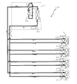
- FIG. 2 is a circuit configuration diagram showing an example of a circuit configuration of the refrigeration cycle apparatus (hereinafter referred to as the refrigeration cycle apparatus 100) according to the first embodiment. Based on FIG. 2, the detailed structure of the refrigerating-cycle apparatus 100 is demonstrated. As shown in FIG. 2, the outdoor unit 1 and the indoor unit 2 are connected by an extension pipe (refrigerant pipe) 4 through which a refrigerant flows.
- extension pipe refrigerant pipe
- Outdoor unit 1 The outdoor unit 1 is mounted with a compressor 10, a refrigerant flow switching device 11 such as a four-way valve, and a heat source side heat exchanger 12 connected in series by a refrigerant pipe.
- the compressor 10 sucks refrigerant and compresses the refrigerant to a high temperature and high pressure state.
- the compressor 10 may be composed of an inverter compressor capable of capacity control.
- the refrigerant flow switching device 11 switches the refrigerant flow during the heating operation and the refrigerant flow during the cooling operation.
- the compressor 10 will be described in detail later.
- the heat source side heat exchanger 12 functions as an evaporator during heating operation, and functions as a condenser (or radiator) during cooling operation.
- the heat source side heat exchanger 12 serving as the first heat exchanger performs heat exchange between air supplied from a blower (not shown) and the refrigerant, and evaporates or condenses the refrigerant. is there.
- the heat source side heat exchanger 12 acts as a condenser in the operation of cooling the indoor space 7. Moreover, in the case of the driving
- the outdoor unit 1 includes a compressor 10, a refrigerant flow switching device 11, a heat source side heat exchanger 12, a high pressure detection device 37, a low pressure detection device 38, and a control device 60.
- the compressor 10 has, for example, a high-pressure shell structure that has a compression chamber in a sealed container, the inside of the sealed container becomes a high-pressure refrigerant pressure atmosphere, and discharges the high-pressure refrigerant compressed in the compression chamber into the sealed container. Is used.
- the outdoor unit 1 includes a control device 60, and controls devices based on detection information from various detection devices, instructions from a remote controller, and the like.
- control device 60 of the present embodiment is configured by a microcomputer or the like having control arithmetic processing means such as a CPU (Central Processing Unit). Moreover, it has a memory
- control arithmetic processing means such as a CPU (Central Processing Unit).
- the indoor unit 2 is equipped with a load-side heat exchanger 15 serving as a second heat exchanger.
- the load side heat exchanger 15 is connected to the outdoor unit 1 by the extension pipe 4.
- the load-side heat exchanger 15 exchanges heat between air supplied from a blower (not shown) and a refrigerant, and generates heating air or cooling air to be supplied to the indoor space 7. .
- the load side heat exchanger 15 acts as a condenser in the case of an operation for heating the indoor space 7. Moreover, in the case of the driving
- FIG. 2 shows an example in which four indoor units 2 are connected, and are illustrated as an indoor unit 2a, an indoor unit 2b, an indoor unit 2c, and an indoor unit 2d from the bottom of the page.
- the load side heat exchanger 15 is also loaded from the lower side of the page with the load side heat exchanger 15a, the load side heat exchanger 15b, the load side heat exchanger 15c, and the load side heat exchange. It is shown as a container 15d.
- the number of connected indoor units 2 is not limited to four as shown in FIG.
- the refrigeration cycle apparatus 100 determines the operation mode of the outdoor unit 1 to be either the cooling operation mode or the heating operation mode based on an instruction from each indoor unit 2. That is, the refrigeration cycle apparatus 100 can perform the same operation (cooling operation or heating operation) for all of the indoor units 2 and adjusts the indoor temperature. Note that each indoor unit 2 can be freely operated / stopped in both the cooling operation mode and the heating operation mode.
- the operation mode executed by the refrigeration cycle apparatus 100 includes a cooling operation mode in which all the driven indoor units 2 perform a cooling operation (including a stop), and all of the driven indoor units 2 are in a heating operation. There is a heating operation mode for executing (including stopping). Below, each operation mode is demonstrated with the flow of a refrigerant
- FIG. 3 is a refrigerant circuit diagram illustrating the refrigerant flow in the cooling operation mode when the discharge temperature of the refrigeration cycle apparatus 100 is low.
- the cooling operation mode will be described by taking as an example a case where a cooling load is generated in all the load-side heat exchangers 15.
- a pipe indicated by a thick line indicates a pipe through which the refrigerant flows, and a flow direction of the refrigerant is indicated by a solid line arrow.
- the refrigerant flow switching device 11 is switched so that the refrigerant discharged from the compressor 10 flows into the heat source side heat exchanger 12.
- the low-temperature and low-pressure refrigerant is compressed by the compressor 10 and discharged as a high-temperature and high-pressure gas refrigerant.
- the high-temperature and high-pressure gas refrigerant discharged from the compressor 10 flows into the heat source side heat exchanger 12 through the refrigerant flow switching device 11. Then, the heat source side heat exchanger 12 condenses and liquefies while radiating heat to the outdoor air, becomes a high-pressure liquid refrigerant, and flows out of the outdoor unit 1.
- the high-pressure liquid refrigerant that has flowed out of the outdoor unit 1 passes through the extension pipe 4 and flows into each of the indoor units 2 (2a to 2d).
- the high-pressure liquid refrigerant that has flowed into the indoor unit 2 (2a to 2d) flows into the expansion device 16 (16a to 16d), and is throttled and decompressed by the expansion device 16 (16a to 16d). It becomes a phase refrigerant. Further, it flows into each of the load side heat exchangers 15 (15a to 15d) acting as an evaporator, absorbs heat from the air flowing around the load side heat exchanger 15, and becomes a low-temperature and low-pressure gas refrigerant.
- the low-temperature and low-pressure gas refrigerant flows out of the indoor unit 2 (2a to 2d), flows again into the outdoor unit 1 through the extension pipe 4, passes through the refrigerant flow switching device 11, and is sucked into the compressor 10 again. Is done.
- the opening degree (opening area) of the expansion devices 16a to 16d is determined based on the detected temperature of the load-side heat exchanger gas refrigerant temperature detection device 28 and the control device 60 of each outdoor unit 2 from the control device 60 of the outdoor unit 1 (FIG. It is controlled so that the temperature difference (superheat degree) between the evaporation temperature transmitted by communication to the target value (not shown) approaches the target value.
- the cooling operation mode when executed, the operation is stopped because there is no need to flow the refrigerant to the load-side heat exchanger 15 (including the thermo-off) without the heat load.
- the expansion device 16 corresponding to the stopped indoor unit 2 is fully closed or set to a small opening at which the refrigerant does not flow.
- FIG. 4 is a refrigerant circuit diagram illustrating a refrigerant flow when the refrigeration cycle apparatus 100 is in the heating operation mode.
- the heating operation mode will be described by taking as an example a case where a thermal load is generated in all the load side heat exchangers 15.
- a pipe indicated by a thick line indicates a pipe through which the refrigerant flows, and a flow direction of the refrigerant is indicated by a solid line arrow.
- the refrigerant flow switching device 11 causes the refrigerant discharged from the compressor 10 to flow into the indoor unit 2 without passing through the heat source side heat exchanger 12. Switch as follows.
- the low-temperature and low-pressure refrigerant is compressed by the compressor 10 and discharged as a high-temperature and high-pressure gas refrigerant, flows out of the outdoor unit 1 through the refrigerant flow switching device 11.
- the high-temperature and high-pressure gas refrigerant that has flowed out of the outdoor unit 1 flows into each of the indoor units 2 (2a to 2d) through the extension pipe 4.
- the high-temperature and high-pressure liquid refrigerant that has flowed out of the load-side heat exchanger 15 (15a to 15d) flows into the expansion device 16 (16a to 16d), is throttled and decompressed by the expansion device 16 (16a to 16d), It becomes a low-pressure two-phase refrigerant and flows out of the indoor unit 2 (2a to 2d).
- the low-temperature and low-pressure two-phase refrigerant that has flowed out of the indoor unit 2 flows into the outdoor unit 1 again through the extension pipe 4.
- the opening degree (opening area) of the expansion devices 16a to 16d is determined based on the condensation temperature transmitted from the control device 60 of the outdoor unit 1 to the control device (not shown) of each indoor unit 2 through communication and the load side heat. Control is performed so that the temperature difference (degree of supercooling) from the detected temperature of the exchanger liquid refrigerant temperature detecting device 27 approaches the target value.
- the low-temperature and low-pressure two-phase refrigerant that has flowed into the outdoor unit 1 flows into the heat source side heat exchanger 12, absorbs heat from the air flowing around the heat source side heat exchanger 12, and evaporates to form a low-temperature and low-pressure gas refrigerant or low-temperature and low-pressure. It becomes a two-phase refrigerant with a large dryness.
- the low-temperature and low-pressure gas refrigerant or the two-phase refrigerant is again sucked into the compressor 10 via the refrigerant flow switching device 11.
- the heating operation mode When the heating operation mode is executed, it is not necessary to flow the refrigerant to the load-side heat exchanger 15 (including the thermo-off) that has no heat load.
- the load-side heat exchanger 15 that is not in operation is set inside.
- the opening degree (opening area) of the expansion device 16 corresponding to the load-side heat exchanger 15 having no heat load is set to a large opening degree such as full opening to prevent accumulation of refrigerant.
- the refrigerant flow switching device 11 generally uses a four-way valve. However, the refrigerant flow switching device 11 is not limited to this, and a plurality of two-way flow switching valves and three-way flow switching valves are used. May be configured to flow.
- the refrigerant is not a refrigerant such as 1,1,2-trifluoroethylene (HFO-1123) represented by C 2 H 1 F 3 and having one double bond in the molecular structure.
- HFO-1123 1,1,2-trifluoroethylene
- a substance that causes a leveling reaction or a mixed refrigerant in which a substance that causes a disproportionation reaction and another substance are mixed is used.
- HC-290 (propane) or the like may be mixed, and any substance having thermal performance that can be used as a refrigerant in a refrigeration cycle apparatus may be used. Any mixing ratio may be used.
- a substance that causes a disproportionation reaction may change into another substance when adjacent substances react when some strong energy is applied from the outside. For this reason, if a substance that causes a disproportionation reaction without using any countermeasure in the refrigerant circuit is used as a refrigerant, it will not function as a refrigerant as a separate substance, but also due to a sudden pressure increase due to heat generation. Accidents such as pipe rupture may occur.
- a disproportionation reaction is particularly likely to occur when the distance between adjacent substances is very close, such as in a liquid state or a two-phase state, but the disproportionation reaction occurs when strong energy is applied even in a gas state. Can happen.
- FIG. 5 is a side sectional view of the compressor 10 as viewed from the side.
- the compressor 10 includes an inflow pipe 41 through which the refrigerant flows into the compressor 10, an outflow pipe 42 through which the refrigerant flows out from the compressor 10, a compression unit 43 that compresses the refrigerant, a motor 44 that is a driving source of the compressor 10, and compression
- a compressor shell 45 (hereinafter referred to as a shell 45), which is a sealed container covering the portion 43 and the motor 44, is provided.
- the motor 44 through which the current flows is disposed on the upper portion of the compression unit 43.
- the motor 44 includes a stator 48 and a rotor 49.
- the stator 48 is fixed to the shell 45.
- the rotor 49 is disposed inside the stator 48 and is connected to the shaft 50.
- FIG. 6 is an enlarged view of the compression unit 43 of the compressor 10.
- the compression unit 43 includes a rolling piston 51.
- the rolling piston 51 is fixed to the same shaft 50 as the rotor 49, and the rotation of the rotor 49 is transmitted to the rolling piston 51.
- the rolling piston 51 is eccentrically attached to the shaft 50.
- the refrigerant flows into the compressor 10 from the inflow pipe 41 and flows into the compression chamber 47 through the suction port 46.
- the compression chamber 47 compresses the flowing refrigerant by changing the volume according to the rotation of the rolling piston 51 by the action of the rolling piston 51, the vane 54, and the vane spring 55 that are eccentrically attached to the shaft 50. .
- the high-temperature and high-pressure gas refrigerant that has been compressed and increased in temperature and pressure is discharged from the discharge valve 53, flows out of the compression chamber 47, and is jetted into the shell 45. At this time, the inside of the shell 45 becomes a high-pressure refrigerant atmosphere.
- the high-temperature and high-pressure gas refrigerant in the shell 45 flows around the motor 44 and flows out of the compressor 10 from the outflow pipe 42.
- the evaporation temperature of the refrigerant is low.
- the discharge temperature of the compressor 10 will become high too much.
- the refrigeration oil deteriorates or the performance of the compressor 10 is extremely deteriorated due to thermal deformation. Therefore, in such a case, the discharge temperature is lowered by causing the compressor 10 to suck in the two-phase refrigerant in which gas and liquid are mixed.
- the types of hermetic compressors include low-pressure shell compressors in addition to the high-pressure shell compressors described above.
- the low-pressure shell type compressor has a compression chamber and a motor in a sealed container. As the refrigerant sucked into the compressor flows into the sealed container, the inside of the sealed container becomes a low-pressure refrigerant atmosphere. And the refrigerant
- the compression part is arranged at the upper part and the motor is arranged at the lower part.
- the liquid component of the two-phase refrigerant that has flowed into the compressor is separated when it flows into the compressor shell before being sucked into the compression chamber. It falls to the lower part of the compressor while colliding with the arranged motor. Further, the liquid refrigerant accumulated in the lower part of the shell is stirred by the shaft for refueling. There is a possibility that a disproportionation reaction of the refrigerant occurs due to collision between the liquid refrigerant accumulated in the lower part of the shell and the motor or stirring by the shaft.
- the high-pressure shell type compressor is configured as described above. For this reason, even when a two-phase refrigerant mixed with gas and liquid is mixed in the compressor 10 in the heating operation mode or the like when the outside air is low, the two-phase refrigerant is directly sucked into the compression chamber 47. And a two-phase refrigerant
- coolant does not collide with structures, such as a motor. Further, since the high-temperature and high-pressure gas refrigerant is jetted into the shell 45, the liquid refrigerant is not accumulated in the lower portion of the shell 45 and stirred by the shaft 50. Therefore, the disproportionation reaction of the refrigerant hardly occurs by configuring the compressor 10 with a high-pressure shell type compressor.
- the two-phase refrigerant having a dryness of 0.8 or more and 0.99 or less is caused to flow and used.
- the gas refrigerant that has been compressed in the compression chamber 47 and heated to a high temperature is discharged into a shell 45 that is a space where the motor 44 is exposed.
- the disproportionation reaction of the refrigerant is likely to occur in a liquid state or a two-phase state where the distance between molecules is short.
- the disproportionation reaction which is a chemical reaction, easily proceeds (the reaction rate increases) when the temperature is high. Therefore, even if the refrigerant is in a gas state, the disproportionation reaction tends to occur if the temperature is high.
- the disproportionation reaction tends to occur if the temperature is high.
- the higher the temperature the easier the reaction proceeds (the reaction rate increases), but the disproportionation reaction tends to occur particularly at a temperature of 50 ° C. or higher.
- the temperature of the refrigerant in the shell 45 of the compressor 10 is almost 50 ° C. or higher in most cases except for a transient state such as at the time of startup. Therefore, it is desirable to introduce as many disproportionation reaction prevention measures as possible.
- a higher temperature tends to cause a disproportionation reaction, and a disproportionation reaction is more likely to occur at 80 ° C. or higher.
- the motor 44 Even if it contacts a high-temperature and high-pressure refrigerant as an insulating material for the motor 44, it is a substance that is not physically or chemically denatured by the refrigerant, and in particular, has solvent resistance, extraction resistance, thermal / chemical stability, A substance having foaming properties or the like is used.
- the insulating material of the motor 44 include an insulating coating material for the winding of the stator 48, an insulating film, an insulating tube, and the like.
- one or more kinds of materials among polyvinyl formal, polyester, THEIC modified polyester, polyamide, polyamide imide, polyester imide, and polyester amide imide are used for the insulating coating material of the winding of the stator 48. ing. Moreover, you may use the enamel coating
- the insulating film of the stator 48 is made of one or more kinds of materials selected from polyethylene terephthalate (PET), polyethylene naphthalate, polyphenylene sulfide (PPS), and polybutylene terephthalate (PBT).
- PET polyethylene terephthalate
- PPS polyphenylene sulfide
- PBT polybutylene terephthalate
- an insulating material for holding a winding such as an insulator
- PEEK polyetheretherketone
- LCP liquid crystal polymer
- Epoxy resin is used for the varnish.
- the insulating tube of the stator 48 is made of one or more kinds of materials selected from polytetrafluoroethylene (PTFE) and tetrafluoroethylene / hexafluoropropylene copolymer resin (FEP). .
- a refrigeration oil having a relatively large volume resistivity such as 2 ⁇ 10 10 ⁇ ⁇ m or more at 20 ° C.
- the volume resistivity is high, the leakage current from the motor 44 is relatively small in the compressor 10, so that the disproportionation reaction of the refrigerant does not easily occur.
- the refrigerant and the refrigeration oil in the shell 45 of the compressor 10 are mixed, and the volume resistivity of the refrigerant-refrigeration oil mixture increases, and it becomes difficult for current to flow through the refrigerant. , Disproportionation reaction is more difficult to occur.
- the solubility is 10 wt% (weight%) or more. Therefore, when the high-pressure shell type compressor 10 is used as the compressor 10, for example, a state in which the temperature of the refrigerant in the shell 45 is 80 ° C. and the pressure is a saturation pressure when the temperature of the refrigerant is 50 ° C. And if the solubility with respect to the refrigerating machine oil of a refrigerant
- coolant can fully be suppressed.
- a refrigerating machine oil what has either a polyol ester and polyvinyl ether as a main component is used. Both the polyol ester and the polyvinyl ether are refrigerating machine oils having relatively high volume resistivity and compatibility with a refrigerant having one double bond in the molecular structure.
- the compression unit 43 is on the lower side and the motor 44 is on the upper side in the shell 45 of the compressor 10 has been described as an example.
- the present invention is not limited to this.
- the part 43 may be on the upper side and the motor 44 may be on the lower side.
- the compressor 10 is a rotary compressor
- a refrigerant sucked into the compressor 10 such as a scroll compressor or a screw compressor is directly sucked into a compression chamber, and after compression, is discharged into a sealed container (shell) so that the inside of the sealed container is a high-pressure refrigerant.
- a sealed container shell
- Any type of high-pressure shell-type compressor can be used as long as it has an atmosphere, and the same effect can be obtained.
- the refrigeration cycle apparatus 100 has several operation modes. In these operation modes, the refrigerant flows through the extension pipe 4 that connects the outdoor unit 1 and the indoor unit 2.
- the high pressure detection device 37 and the low pressure detection device 38 are installed to control the refrigeration cycle high pressure and low pressure to target values, but may be a temperature detection device that detects a saturation temperature.
- the refrigerant flow switching device 11 is shown as if it were a four-way valve, but is not limited to this, and a plurality of two-way flow switching valves and three-way flow switching valves are used, and the refrigerant is similarly You may comprise so that it may flow.
- the heat source side heat exchanger 12 and the load side heat exchangers 15a to 15d are provided with a blower, and in many cases, condensation or evaporation is promoted by blowing, but this is not restrictive.
- a blower for example, as the load side heat exchangers 15a to 15d, a panel heater using radiation can be used, and as the heat source side heat exchanger 12, a water-cooled type that moves heat by water or antifreeze. Things can also be used. Any heat exchanger having a structure capable of radiating or absorbing heat can be used.
- the indoor unit 2 can arbitrarily select one of a cooling operation and a heating operation, and the entire system can perform a mixed operation of the indoor unit 2 that performs the cooling operation and the indoor unit 2 that performs the heating operation.
- the present invention can also be applied to a refrigeration cycle apparatus and has the same effect.
- a plate-type heat exchanger that exchanges heat with water, antifreeze liquid, or the like is used as the load-side heat exchanger 15, and the heat-exchanged water, antifreeze liquid, or the like is circulated to the indoor unit, and the temperature is adjusted to the air-conditioning target space.
- It may be a refrigeration cycle apparatus configured to supply fresh air.
- FIG. FIG. 7 is a circuit diagram of the refrigeration cycle apparatus according to Embodiment 2 of the present invention.
- an accumulator 19 that is connected to the compressor 10 on the suction side and stores excess refrigerant.
- a bypass pipe 20 that branches a part of the refrigerant discharged from the compressor 10 and flows to the suction side of the compressor 10 is provided.
- the bypass expansion device 17 a adjusts the amount of refrigerant that passes through the bypass pipe 20.
- the expansion device 17b generates an intermediate pressure by adjusting the opening during heating operation, and is used in a fully opened state during cooling operation.
- the inter-refrigerant heat exchanger 18 liquefies the refrigerant flowing into the bypass expansion device 17a by exchanging heat between the refrigerant passing through the bypass pipe 20 before and after the bypass expansion device 17a.
- the accumulator 19 When the accumulator 19 is provided on the suction side of the compressor 10, the liquid component of the two-phase refrigerant is separated by the accumulator 19 and collected in the accumulator 19. For this reason, only a slightly wet refrigerant with a high degree of dryness is returned from the accumulator 19 to the compressor 10. Therefore, when the discharge temperature of the compressor 10 is lowered in the heating operation mode, for example, the refrigerant is branched from the lower side of the pipe through which the liquid part during cooling operation (two-phase part during heating operation) passes in the refrigerant circuit. The bypass pipe 20 is passed.
- the compressor 10 may be able to suck the refrigerant in the two-phase state.
- Heat source unit (outdoor unit), 2a, 2b, 2c, 2d indoor unit, 3 heat medium converter, 4 extension pipe (refrigerant pipe), 4a first connection pipe, 4b second connection pipe, 5 pipe (heat medium pipe) ), 6 outdoor space, 7 indoor space, 8 outdoor space such as the back of the ceiling and indoor space, 9 buildings, 10 compressors, 11 refrigerant flow switching device (four-way valve), 12 heat source side Heat exchanger, 15, 15a, 15b, 15c, 15d load side heat exchanger, 16, 16a, 16b, 16c, 16d expansion device, 17a bypass expansion device, 17b expansion device, 18 inter-refrigerant heat exchanger, 19 accumulator, 20 bypass piping, 27, 27a, 27b, 27c, 27d load side heat exchanger liquid refrigerant temperature detection device, 28, 28a, 28b, 28c, 28d load side heat exchanger gas Medium temperature detection device, 37 High pressure detection device, 38 Low pressure detection device, 41 Inflow pipe, 42 Outflow pipe, 43 Compression section, 44
Landscapes
- Engineering & Computer Science (AREA)
- Chemical & Material Sciences (AREA)
- Mechanical Engineering (AREA)
- General Engineering & Computer Science (AREA)
- Physics & Mathematics (AREA)
- Thermal Sciences (AREA)
- Chemical Kinetics & Catalysis (AREA)
- Organic Chemistry (AREA)
- Materials Engineering (AREA)
- Combustion & Propulsion (AREA)
- General Chemical & Material Sciences (AREA)
- Oil, Petroleum & Natural Gas (AREA)
- Analytical Chemistry (AREA)
- Power Engineering (AREA)
- Compression-Type Refrigeration Machines With Reversible Cycles (AREA)
- Applications Or Details Of Rotary Compressors (AREA)
Abstract
Priority Applications (4)
| Application Number | Priority Date | Filing Date | Title |
|---|---|---|---|
| JP2016508340A JPWO2015140880A1 (ja) | 2014-03-17 | 2014-03-17 | 圧縮機及び冷凍サイクル装置 |
| US15/125,219 US20170097176A1 (en) | 2014-03-17 | 2014-03-17 | Compressor and refrigeration cycle apparatus |
| PCT/JP2014/057040 WO2015140880A1 (fr) | 2014-03-17 | 2014-03-17 | Compresseur et appareil à cycle de réfrigération |
| EP14886486.1A EP3121536A1 (fr) | 2014-03-17 | 2014-03-17 | Compresseur et appareil à cycle de réfrigération |
Applications Claiming Priority (1)
| Application Number | Priority Date | Filing Date | Title |
|---|---|---|---|
| PCT/JP2014/057040 WO2015140880A1 (fr) | 2014-03-17 | 2014-03-17 | Compresseur et appareil à cycle de réfrigération |
Publications (1)
| Publication Number | Publication Date |
|---|---|
| WO2015140880A1 true WO2015140880A1 (fr) | 2015-09-24 |
Family
ID=54143906
Family Applications (1)
| Application Number | Title | Priority Date | Filing Date |
|---|---|---|---|
| PCT/JP2014/057040 Ceased WO2015140880A1 (fr) | 2014-03-17 | 2014-03-17 | Compresseur et appareil à cycle de réfrigération |
Country Status (4)
| Country | Link |
|---|---|
| US (1) | US20170097176A1 (fr) |
| EP (1) | EP3121536A1 (fr) |
| JP (1) | JPWO2015140880A1 (fr) |
| WO (1) | WO2015140880A1 (fr) |
Cited By (2)
| Publication number | Priority date | Publication date | Assignee | Title |
|---|---|---|---|---|
| JP2018025326A (ja) * | 2016-08-09 | 2018-02-15 | パナソニックIpマネジメント株式会社 | 冷凍サイクル装置 |
| JP2022013930A (ja) * | 2020-07-03 | 2022-01-18 | ダイキン工業株式会社 | 圧縮機における冷媒としての使用、圧縮機、および、冷凍サイクル装置 |
Families Citing this family (4)
| Publication number | Priority date | Publication date | Assignee | Title |
|---|---|---|---|---|
| JP2018177953A (ja) * | 2017-04-12 | 2018-11-15 | 出光興産株式会社 | 冷凍機油、及び冷凍機用組成物 |
| CN107152811A (zh) * | 2017-06-30 | 2017-09-12 | 美的集团武汉制冷设备有限公司 | 空调系统及空调系统的控制方法 |
| JP6696533B2 (ja) * | 2018-06-22 | 2020-05-20 | ダイキン工業株式会社 | 冷凍装置 |
| CN115769030A (zh) * | 2020-07-03 | 2023-03-07 | 大金工业株式会社 | 在压缩机中作为制冷剂的用途、压缩机和制冷循环装置 |
Citations (7)
| Publication number | Priority date | Publication date | Assignee | Title |
|---|---|---|---|---|
| JP2010002099A (ja) * | 2008-06-19 | 2010-01-07 | Mitsubishi Electric Corp | 冷凍サイクル装置 |
| JP2010156524A (ja) * | 2009-01-05 | 2010-07-15 | Mitsubishi Electric Corp | 冷凍サイクル装置 |
| JP2012131994A (ja) * | 2010-11-30 | 2012-07-12 | Jx Nippon Oil & Energy Corp | 冷凍機用作動流体組成物および冷凍機油 |
| WO2012157764A1 (fr) * | 2011-05-19 | 2012-11-22 | 旭硝子株式会社 | Fluide moteur, et système à cycle thermique |
| JP2013011391A (ja) * | 2011-06-29 | 2013-01-17 | Panasonic Corp | 冷凍サイクル装置およびそれを備えた温水生成装置 |
| JP2013124800A (ja) * | 2011-12-14 | 2013-06-24 | Panasonic Corp | 冷凍サイクル装置 |
| JP2013241389A (ja) * | 2012-04-25 | 2013-12-05 | Asahi Glass Co Ltd | フルオロオレフィンを含む流体の乾燥方法、およびフルオロオレフィンの製造方法 |
Family Cites Families (8)
| Publication number | Priority date | Publication date | Assignee | Title |
|---|---|---|---|---|
| JP2967574B2 (ja) * | 1990-11-16 | 1999-10-25 | 株式会社日立製作所 | 冷凍装置 |
| JP3501258B2 (ja) * | 1996-11-18 | 2004-03-02 | 出光興産株式会社 | 冷凍装置及び冷媒圧縮機 |
| JP5103952B2 (ja) * | 2007-03-08 | 2012-12-19 | ダイキン工業株式会社 | 冷凍装置 |
| JP5407157B2 (ja) * | 2008-03-18 | 2014-02-05 | ダイキン工業株式会社 | 冷凍装置 |
| US8037712B2 (en) * | 2008-10-28 | 2011-10-18 | Lg Electronics Inc. | Hermetic compressor and refrigeration cycle having the same |
| WO2012012496A2 (fr) * | 2010-07-23 | 2012-01-26 | Carrier Corporation | Séparateur de réfrigérant à cycle d'éjection |
| FR2973717B1 (fr) * | 2011-04-08 | 2013-03-29 | Ceca Sa | Procede de reduction de l'acidite totale de compositions frigorigenes |
| JP5522288B2 (ja) * | 2011-09-30 | 2014-06-18 | ダイキン工業株式会社 | 冷凍装置 |
-
2014
- 2014-03-17 JP JP2016508340A patent/JPWO2015140880A1/ja active Pending
- 2014-03-17 WO PCT/JP2014/057040 patent/WO2015140880A1/fr not_active Ceased
- 2014-03-17 US US15/125,219 patent/US20170097176A1/en not_active Abandoned
- 2014-03-17 EP EP14886486.1A patent/EP3121536A1/fr not_active Withdrawn
Patent Citations (7)
| Publication number | Priority date | Publication date | Assignee | Title |
|---|---|---|---|---|
| JP2010002099A (ja) * | 2008-06-19 | 2010-01-07 | Mitsubishi Electric Corp | 冷凍サイクル装置 |
| JP2010156524A (ja) * | 2009-01-05 | 2010-07-15 | Mitsubishi Electric Corp | 冷凍サイクル装置 |
| JP2012131994A (ja) * | 2010-11-30 | 2012-07-12 | Jx Nippon Oil & Energy Corp | 冷凍機用作動流体組成物および冷凍機油 |
| WO2012157764A1 (fr) * | 2011-05-19 | 2012-11-22 | 旭硝子株式会社 | Fluide moteur, et système à cycle thermique |
| JP2013011391A (ja) * | 2011-06-29 | 2013-01-17 | Panasonic Corp | 冷凍サイクル装置およびそれを備えた温水生成装置 |
| JP2013124800A (ja) * | 2011-12-14 | 2013-06-24 | Panasonic Corp | 冷凍サイクル装置 |
| JP2013241389A (ja) * | 2012-04-25 | 2013-12-05 | Asahi Glass Co Ltd | フルオロオレフィンを含む流体の乾燥方法、およびフルオロオレフィンの製造方法 |
Cited By (2)
| Publication number | Priority date | Publication date | Assignee | Title |
|---|---|---|---|---|
| JP2018025326A (ja) * | 2016-08-09 | 2018-02-15 | パナソニックIpマネジメント株式会社 | 冷凍サイクル装置 |
| JP2022013930A (ja) * | 2020-07-03 | 2022-01-18 | ダイキン工業株式会社 | 圧縮機における冷媒としての使用、圧縮機、および、冷凍サイクル装置 |
Also Published As
| Publication number | Publication date |
|---|---|
| JPWO2015140880A1 (ja) | 2017-04-06 |
| US20170097176A1 (en) | 2017-04-06 |
| EP3121536A1 (fr) | 2017-01-25 |
Similar Documents
| Publication | Publication Date | Title |
|---|---|---|
| US10590934B2 (en) | Refrigeration cycle device with motor speed estimator | |
| US10508847B2 (en) | Refrigeration apparatus | |
| US9459013B2 (en) | Air-conditioning apparatus with safety measure for ventilation of inflammable refrigerant from heat exchanger | |
| EP2960597B1 (fr) | Dispositif de climatisation | |
| US9709304B2 (en) | Air-conditioning apparatus | |
| US20210348820A1 (en) | Heat load processing system | |
| EP3764025B1 (fr) | Appareil à cycle frigorifique | |
| EP3764027A1 (fr) | Dispositif à cycle de réfrigération | |
| US10852007B2 (en) | Heat pump device | |
| WO2015140880A1 (fr) | Compresseur et appareil à cycle de réfrigération | |
| WO2016181529A1 (fr) | Dispositif à cycle de réfrigération | |
| JPWO2019198175A1 (ja) | 冷凍サイクル装置 | |
| CN105980791A (zh) | 制冷循环装置 | |
| JP2012122677A (ja) | 空気調和機 | |
| WO2015140881A1 (fr) | Appareil à cycle de réfrigération | |
| WO2023002522A1 (fr) | Dispositif de climatisation et procédé d'installation de dispositif de climatisation | |
| WO2019130383A1 (fr) | Dispositif de climatisation | |
| EP3882536A1 (fr) | Climatiseur | |
| KR20140103262A (ko) | 공기 조화기 | |
| JP7139850B2 (ja) | 冷凍サイクル装置 | |
| WO2015140877A1 (fr) | Dispositif d'étranglement et dispositif à cycle frigorifique | |
| JPH10259961A (ja) | 空気調和装置 | |
| CN121941884A (zh) | 冷冻循环装置 |
Legal Events
| Date | Code | Title | Description |
|---|---|---|---|
| 121 | Ep: the epo has been informed by wipo that ep was designated in this application |
Ref document number: 14886486 Country of ref document: EP Kind code of ref document: A1 |
|
| ENP | Entry into the national phase |
Ref document number: 2016508340 Country of ref document: JP Kind code of ref document: A |
|
| WWE | Wipo information: entry into national phase |
Ref document number: 15125219 Country of ref document: US |
|
| REEP | Request for entry into the european phase |
Ref document number: 2014886486 Country of ref document: EP |
|
| WWE | Wipo information: entry into national phase |
Ref document number: 2014886486 Country of ref document: EP |
|
| NENP | Non-entry into the national phase |
Ref country code: DE |