WO2015140884A1 - 冷凍サイクル装置 - Google Patents
冷凍サイクル装置 Download PDFInfo
- Publication number
- WO2015140884A1 WO2015140884A1 PCT/JP2014/057046 JP2014057046W WO2015140884A1 WO 2015140884 A1 WO2015140884 A1 WO 2015140884A1 JP 2014057046 W JP2014057046 W JP 2014057046W WO 2015140884 A1 WO2015140884 A1 WO 2015140884A1
- Authority
- WO
- WIPO (PCT)
- Prior art keywords
- refrigerant
- refrigeration cycle
- cycle apparatus
- compressor
- heat exchanger
- Prior art date
- Legal status (The legal status is an assumption and is not a legal conclusion. Google has not performed a legal analysis and makes no representation as to the accuracy of the status listed.)
- Ceased
Links
Images


Classifications
-
- F—MECHANICAL ENGINEERING; LIGHTING; HEATING; WEAPONS; BLASTING
- F25—REFRIGERATION OR COOLING; COMBINED HEATING AND REFRIGERATION SYSTEMS; HEAT PUMP SYSTEMS; MANUFACTURE OR STORAGE OF ICE; LIQUEFACTION SOLIDIFICATION OF GASES
- F25B—REFRIGERATION MACHINES, PLANTS OR SYSTEMS; COMBINED HEATING AND REFRIGERATION SYSTEMS; HEAT PUMP SYSTEMS
- F25B49/00—Arrangement or mounting of control or safety devices
- F25B49/02—Arrangement or mounting of control or safety devices for compression type machines, plants or systems
-
- C—CHEMISTRY; METALLURGY
- C09—DYES; PAINTS; POLISHES; NATURAL RESINS; ADHESIVES; COMPOSITIONS NOT OTHERWISE PROVIDED FOR; APPLICATIONS OF MATERIALS NOT OTHERWISE PROVIDED FOR
- C09K—MATERIALS FOR MISCELLANEOUS APPLICATIONS, NOT PROVIDED FOR ELSEWHERE
- C09K5/00—Heat-transfer, heat-exchange or heat-storage materials, e.g. refrigerants; Materials for the production of heat or cold by chemical reactions other than by combustion
- C09K5/02—Materials undergoing a change of physical state when used
- C09K5/04—Materials undergoing a change of physical state when used the change of state being from liquid to vapour or vice versa
- C09K5/041—Materials undergoing a change of physical state when used the change of state being from liquid to vapour or vice versa for compression-type refrigeration systems
- C09K5/044—Materials undergoing a change of physical state when used the change of state being from liquid to vapour or vice versa for compression-type refrigeration systems comprising halogenated compounds
- C09K5/045—Materials undergoing a change of physical state when used the change of state being from liquid to vapour or vice versa for compression-type refrigeration systems comprising halogenated compounds containing only fluorine as halogen
-
- F—MECHANICAL ENGINEERING; LIGHTING; HEATING; WEAPONS; BLASTING
- F25—REFRIGERATION OR COOLING; COMBINED HEATING AND REFRIGERATION SYSTEMS; HEAT PUMP SYSTEMS; MANUFACTURE OR STORAGE OF ICE; LIQUEFACTION SOLIDIFICATION OF GASES
- F25B—REFRIGERATION MACHINES, PLANTS OR SYSTEMS; COMBINED HEATING AND REFRIGERATION SYSTEMS; HEAT PUMP SYSTEMS
- F25B40/00—Subcoolers, desuperheaters or superheaters
-
- F—MECHANICAL ENGINEERING; LIGHTING; HEATING; WEAPONS; BLASTING
- F25—REFRIGERATION OR COOLING; COMBINED HEATING AND REFRIGERATION SYSTEMS; HEAT PUMP SYSTEMS; MANUFACTURE OR STORAGE OF ICE; LIQUEFACTION SOLIDIFICATION OF GASES
- F25B—REFRIGERATION MACHINES, PLANTS OR SYSTEMS; COMBINED HEATING AND REFRIGERATION SYSTEMS; HEAT PUMP SYSTEMS
- F25B41/00—Fluid-circulation arrangements
- F25B41/20—Disposition of valves, e.g. of on-off valves or flow control valves
-
- F—MECHANICAL ENGINEERING; LIGHTING; HEATING; WEAPONS; BLASTING
- F25—REFRIGERATION OR COOLING; COMBINED HEATING AND REFRIGERATION SYSTEMS; HEAT PUMP SYSTEMS; MANUFACTURE OR STORAGE OF ICE; LIQUEFACTION SOLIDIFICATION OF GASES
- F25B—REFRIGERATION MACHINES, PLANTS OR SYSTEMS; COMBINED HEATING AND REFRIGERATION SYSTEMS; HEAT PUMP SYSTEMS
- F25B9/00—Compression machines, plants or systems, in which the refrigerant is air or other gas of low boiling point
- F25B9/002—Compression machines, plants or systems, in which the refrigerant is air or other gas of low boiling point characterised by the refrigerant
- F25B9/006—Compression machines, plants or systems, in which the refrigerant is air or other gas of low boiling point characterised by the refrigerant the refrigerant containing more than one component
-
- C—CHEMISTRY; METALLURGY
- C09—DYES; PAINTS; POLISHES; NATURAL RESINS; ADHESIVES; COMPOSITIONS NOT OTHERWISE PROVIDED FOR; APPLICATIONS OF MATERIALS NOT OTHERWISE PROVIDED FOR
- C09K—MATERIALS FOR MISCELLANEOUS APPLICATIONS, NOT PROVIDED FOR ELSEWHERE
- C09K2205/00—Aspects relating to compounds used in compression type refrigeration systems
- C09K2205/10—Components
- C09K2205/12—Hydrocarbons
- C09K2205/126—Unsaturated fluorinated hydrocarbons
-
- C—CHEMISTRY; METALLURGY
- C09—DYES; PAINTS; POLISHES; NATURAL RESINS; ADHESIVES; COMPOSITIONS NOT OTHERWISE PROVIDED FOR; APPLICATIONS OF MATERIALS NOT OTHERWISE PROVIDED FOR
- C09K—MATERIALS FOR MISCELLANEOUS APPLICATIONS, NOT PROVIDED FOR ELSEWHERE
- C09K2205/00—Aspects relating to compounds used in compression type refrigeration systems
- C09K2205/32—The mixture being azeotropic
-
- F—MECHANICAL ENGINEERING; LIGHTING; HEATING; WEAPONS; BLASTING
- F25—REFRIGERATION OR COOLING; COMBINED HEATING AND REFRIGERATION SYSTEMS; HEAT PUMP SYSTEMS; MANUFACTURE OR STORAGE OF ICE; LIQUEFACTION SOLIDIFICATION OF GASES
- F25B—REFRIGERATION MACHINES, PLANTS OR SYSTEMS; COMBINED HEATING AND REFRIGERATION SYSTEMS; HEAT PUMP SYSTEMS
- F25B2400/00—General features or devices for refrigeration machines, plants or systems, combined heating and refrigeration systems or heat-pump systems, i.e. not limited to a particular subgroup of F25B
- F25B2400/01—Heaters
-
- F—MECHANICAL ENGINEERING; LIGHTING; HEATING; WEAPONS; BLASTING
- F25—REFRIGERATION OR COOLING; COMBINED HEATING AND REFRIGERATION SYSTEMS; HEAT PUMP SYSTEMS; MANUFACTURE OR STORAGE OF ICE; LIQUEFACTION SOLIDIFICATION OF GASES
- F25B—REFRIGERATION MACHINES, PLANTS OR SYSTEMS; COMBINED HEATING AND REFRIGERATION SYSTEMS; HEAT PUMP SYSTEMS
- F25B2400/00—General features or devices for refrigeration machines, plants or systems, combined heating and refrigeration systems or heat-pump systems, i.e. not limited to a particular subgroup of F25B
- F25B2400/05—Compression system with heat exchange between particular parts of the system
- F25B2400/051—Compression system with heat exchange between particular parts of the system between the accumulator and another part of the cycle
-
- F—MECHANICAL ENGINEERING; LIGHTING; HEATING; WEAPONS; BLASTING
- F25—REFRIGERATION OR COOLING; COMBINED HEATING AND REFRIGERATION SYSTEMS; HEAT PUMP SYSTEMS; MANUFACTURE OR STORAGE OF ICE; LIQUEFACTION SOLIDIFICATION OF GASES
- F25B—REFRIGERATION MACHINES, PLANTS OR SYSTEMS; COMBINED HEATING AND REFRIGERATION SYSTEMS; HEAT PUMP SYSTEMS
- F25B2400/00—General features or devices for refrigeration machines, plants or systems, combined heating and refrigeration systems or heat-pump systems, i.e. not limited to a particular subgroup of F25B
- F25B2400/12—Inflammable refrigerants
- F25B2400/121—Inflammable refrigerants using R1234
-
- F—MECHANICAL ENGINEERING; LIGHTING; HEATING; WEAPONS; BLASTING
- F25—REFRIGERATION OR COOLING; COMBINED HEATING AND REFRIGERATION SYSTEMS; HEAT PUMP SYSTEMS; MANUFACTURE OR STORAGE OF ICE; LIQUEFACTION SOLIDIFICATION OF GASES
- F25B—REFRIGERATION MACHINES, PLANTS OR SYSTEMS; COMBINED HEATING AND REFRIGERATION SYSTEMS; HEAT PUMP SYSTEMS
- F25B2400/00—General features or devices for refrigeration machines, plants or systems, combined heating and refrigeration systems or heat-pump systems, i.e. not limited to a particular subgroup of F25B
- F25B2400/23—Separators
-
- F—MECHANICAL ENGINEERING; LIGHTING; HEATING; WEAPONS; BLASTING
- F25—REFRIGERATION OR COOLING; COMBINED HEATING AND REFRIGERATION SYSTEMS; HEAT PUMP SYSTEMS; MANUFACTURE OR STORAGE OF ICE; LIQUEFACTION SOLIDIFICATION OF GASES
- F25B—REFRIGERATION MACHINES, PLANTS OR SYSTEMS; COMBINED HEATING AND REFRIGERATION SYSTEMS; HEAT PUMP SYSTEMS
- F25B2500/00—Problems to be solved
- F25B2500/26—Problems to be solved characterised by the startup of the refrigeration cycle
-
- F—MECHANICAL ENGINEERING; LIGHTING; HEATING; WEAPONS; BLASTING
- F25—REFRIGERATION OR COOLING; COMBINED HEATING AND REFRIGERATION SYSTEMS; HEAT PUMP SYSTEMS; MANUFACTURE OR STORAGE OF ICE; LIQUEFACTION SOLIDIFICATION OF GASES
- F25B—REFRIGERATION MACHINES, PLANTS OR SYSTEMS; COMBINED HEATING AND REFRIGERATION SYSTEMS; HEAT PUMP SYSTEMS
- F25B2600/00—Control issues
- F25B2600/25—Control of valves
- F25B2600/2507—Flow-diverting valves
-
- F—MECHANICAL ENGINEERING; LIGHTING; HEATING; WEAPONS; BLASTING
- F25—REFRIGERATION OR COOLING; COMBINED HEATING AND REFRIGERATION SYSTEMS; HEAT PUMP SYSTEMS; MANUFACTURE OR STORAGE OF ICE; LIQUEFACTION SOLIDIFICATION OF GASES
- F25B—REFRIGERATION MACHINES, PLANTS OR SYSTEMS; COMBINED HEATING AND REFRIGERATION SYSTEMS; HEAT PUMP SYSTEMS
- F25B2700/00—Sensing or detecting of parameters; Sensors therefor
- F25B2700/04—Refrigerant level
-
- F—MECHANICAL ENGINEERING; LIGHTING; HEATING; WEAPONS; BLASTING
- F25—REFRIGERATION OR COOLING; COMBINED HEATING AND REFRIGERATION SYSTEMS; HEAT PUMP SYSTEMS; MANUFACTURE OR STORAGE OF ICE; LIQUEFACTION SOLIDIFICATION OF GASES
- F25B—REFRIGERATION MACHINES, PLANTS OR SYSTEMS; COMBINED HEATING AND REFRIGERATION SYSTEMS; HEAT PUMP SYSTEMS
- F25B2700/00—Sensing or detecting of parameters; Sensors therefor
- F25B2700/21—Temperatures
- F25B2700/2103—Temperatures near a heat exchanger
Definitions
- the present invention relates to a refrigeration cycle apparatus using a non-azeotropic refrigerant mixture as a working refrigerant.
- R410A is a refrigerant with good performance, but since GWP (global warming potential) is about 2000, R32 having GWP of about 1/3 is being used.
- R32 is a refrigerant that has relatively close physical properties to R410A and good performance, but has a GWP of about 600, and a fluoropropene (HFO) refrigerant such as HFO-1234yf has been developed to further reduce GWP.
- HFO fluoropropene
- this refrigerant is a high boiling point refrigerant and has low performance. If trying to maintain the same performance as before, there are many technical problems and the cost may increase. Accordingly, a refrigeration cycle apparatus that employs a refrigerant having a low global warming potential and a low boiling point (for example, HFO-1123) has been proposed (see Patent Document 1).
- HFO-1123 has little influence on the ozone layer because it does not contain chlorine atoms in its composition, and has little influence on global warming because it has a double bond and has a short atmospheric life. It is known to be excellent (low boiling point refrigerant).
- the combustion classification according to ASHRAE is in the category of rank 2L (low flammability) and has safety.
- refrigerants such as HC, HFC, HCFO, CFO, and HFO can be mixed with HFO-1123 to partially enjoy such advantages as a non-azeotropic refrigerant mixture.
- a refrigeration cycle apparatus using a non-azeotropic refrigerant mixture as a working refrigerant, excess refrigerant rich in high-boiling refrigerant is stored as liquid refrigerant in an accumulator or the like, so that the composition ratio of the circulating refrigerant changes, resulting in reduced performance or high pressure. It is known that there is a possibility of causing a problem due to the rise (see Patent Document 2).
- a disproportionation reaction is a chemical reaction in which two or more of the same type of molecule react with each other to produce two or more different types of products.
- the reaction may occur in a chain manner under a high temperature and high pressure environment.
- HFO-1123 is not used alone, but is used with a reduced composition ratio as one of the non-azeotropic refrigerants. If excess refrigerant rich in high-boiling refrigerant is stored as liquid refrigerant, the composition ratio of HFO-1123, which is a low-boiling refrigerant, will be high in the refrigerant circuit, and the above-mentioned non-uniformity under high temperature and high pressure conditions. There is a problem that the possibility of the chemical reaction increases.
- the present invention has been made to solve the above-described problems. Even if a refrigerant in which such a disproportionation reaction occurs is used as a non-azeotropic refrigerant mixture in a refrigeration cycle apparatus, the refrigerant An object of the present invention is to provide a refrigeration cycle apparatus that is safe and has high performance by avoiding the condition that causes disproportionation reaction.
- a refrigeration cycle apparatus uses a non-azeotropic refrigerant mixture including a first refrigerant and a second refrigerant having a higher boiling point than the first refrigerant under the same pressure as a working refrigerant
- 1 is a refrigeration cycle apparatus including at least a main path in which a heat exchanger, an expansion valve, a gas-liquid separator, and a second heat exchanger are sequentially connected, and the first refrigerant has a disproportionation reaction.
- the initial operation is performed to suppress the temperature or pressure of the refrigerant discharged from the compressor based on the amount of liquid refrigerant in the gas-liquid separator as compared with the normal operation. Is what you do.
- the composition ratio of the first refrigerant and the second refrigerant in the cycle can be appropriately improved immediately from the state where the liquid refrigerant is stored in the accumulator immediately after the start of the compressor, While reducing the partial pressure of the 1st refrigerant
- FIG. 1 is a schematic configuration diagram of a refrigeration cycle apparatus according to Embodiment 1.
- FIG. FIG. 3 is a cross-sectional view of the accumulator according to the first embodiment.
- FIG. 6 is a cross-sectional view of another example in the accumulator according to the first embodiment.
- FIG. 3 is a diagram showing the operation of the refrigerant in the initial state of the start of operation of the refrigeration cycle apparatus according to Embodiment 1.
- FIG. 3 is a diagram showing the operation of the refrigerant during normal operation of the refrigeration cycle apparatus according to Embodiment 1.
- 2 is a control flow diagram of the refrigeration cycle apparatus according to Embodiment 1.
- FIG. 6 is a schematic configuration diagram of a refrigeration cycle apparatus according to Embodiment 2.
- FIG. 6 is a diagram showing refrigerant operation in an initial state of operation start of the refrigeration cycle apparatus according to Embodiment 2.
- FIG. 6 is a diagram showing refrigerant operation in an initial state of operation start of the refrigeration cycle apparatus according to Embodiment 2.
- 6 is a diagram illustrating refrigerant operation during normal operation of the refrigeration cycle apparatus according to Embodiment 2.
- 6 is a schematic configuration diagram of a refrigeration cycle apparatus according to Embodiment 3.
- FIG. It is a schematic block diagram when the hot gas bypass valve of the refrigeration cycle apparatus which concerns on Embodiment 4 is open. It is a schematic block diagram of another example when the hot gas bypass valve of the refrigeration cycle apparatus according to Embodiment 4 is open.
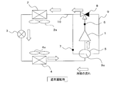
- FIG. 1 is a schematic configuration diagram of a refrigeration cycle apparatus according to Embodiment 1.
- the refrigeration cycle apparatus according to Embodiment 1 includes a compressor 1, a condenser 2, an expansion valve 3, an evaporator 4, and an accumulator 5 (corresponding to the gas-liquid separator of the present invention). ) And the main path 10 are sequentially connected. Further, a bypass path 9 is provided that branches from the discharge side of the compressor 1 in the main path 10, passes through the accumulator 5 through the three-way valve 8, and is connected to the inlet side of the condenser 2 in the main path 10. And these each component is connected by refrigerant
- the bypass path 9 is provided with a heat exchanging portion 9a between the bypass path 9 and the accumulator 5, and a first temperature detecting means 6 and a second temperature detecting means 7 are provided across the heat exchanging section 9a. Yes.
- the first temperature detection means 6 detects the temperature on the discharge side of the compressor 1, and the second temperature detection means 7 passes after the refrigerant discharged from the compressor 1 passes through the accumulator 5 and exchanges heat with the heat exchanging section 9a. The temperature is detected.
- FIG. 2 is a cross-sectional view of the accumulator according to the first embodiment.
- FIG. 3 shows a sectional view of another example in the accumulator according to the first embodiment.
- the refrigerant in the gas state or two-phase state flowing into the accumulator 5 from the evaporator 4 is separated in the accumulator 5, and only the gas component flows into the suction port of the compressor 1 through the U-shaped pipe. It has a structure.
- the discharged gas refrigerant discharged from the compressor 1 has a structure that passes through the bypass path 9 and indirectly contacts the liquid refrigerant in the accumulator 5 through the heat exchanging portion 9a.
- the heat exchanging part 9a is provided at a position not less than 5% and not more than 50% from the lower end of the effective internal height of the accumulator 5, and as shown in FIG.
- the liquid refrigerant can be heated with this heat.
- the pipe may be wound from the bottom to the top or from the top to the bottom.
- FIG. 4 is a diagram showing the operation of the refrigerant in the initial state of the operation start of the refrigeration cycle apparatus according to Embodiment 1.
- FIG. 5 is a diagram showing the operation of the refrigerant during normal operation of the refrigeration cycle apparatus according to Embodiment 1.
- FIG. 6 is a control flow diagram of the refrigeration cycle apparatus according to Embodiment 1.
- FIG. 7 is a diagram showing a temperature gradient of the gas refrigerant before and after the accumulator of the refrigeration cycle apparatus according to Embodiment 1.
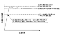
- FIG. 8 is a diagram showing a change in temperature of the refrigerant discharged from the compressor in the initial state of operation start of the refrigeration cycle apparatus according to Embodiment 1.
- FIG. 9 is a diagram showing a temperature change of the refrigerant discharged from the compressor in the normal operation of the conventional refrigeration cycle apparatus.
- the operating refrigerant of the refrigeration cycle apparatus according to Embodiment 1 is a non-azeotropic refrigerant mixture, a low boiling point refrigerant (corresponding to the first refrigerant of the present invention) and a high boiling point refrigerant (corresponding to the second refrigerant of the present invention). It is composed of
- the low-boiling point refrigerant (first refrigerant) has a characteristic that tends to cause a disproportionation reaction when a certain amount of energy is applied under conditions of high temperature and high pressure.
- a high boiling point refrigerant (second refrigerant) is less likely to cause a disproportionation reaction than a low boiling point refrigerant (first refrigerant) under the same conditions as a low boiling point refrigerant (first refrigerant) (or a disproportionation reaction under the same conditions). It is a refrigerant having the characteristics of
- the low boiling point refrigerant (first refrigerant) is disproportionated under specific conditions (high temperature and high pressure conditions) that are the same as the pressure and temperature at which the high boiling point refrigerant (second refrigerant) does not cause any disproportionation reaction. It is a refrigerant with characteristics that are likely to occur. Further, the high boiling point refrigerant (second refrigerant) has a characteristic that the boiling point is higher (evaporation is difficult) under the same pressure than the low boiling point refrigerant (first refrigerant).
- first refrigerant for example, HFO-1123
- second refrigerant for example, R32, HF0-1234yf, HFO-1234ze, or the like
- Refrigerating machine oil generally contains additives, but monocyclic monoterpenoids are contained as reaction inhibitors for low boiling point refrigerants (first refrigerants).
- the monocyclic monoterpenoid includes, for example, limonene. It is known that the reaction is easily suppressed when the low boiling point refrigerant (first refrigerant) is 70% or less in terms of molar ratio.
- the high boiling point refrigerant (second refrigerant) is not limited to one type, and may be two or more types.
- a non-azeotropic refrigerant mixture for example, a refrigerant mixture of HFO-1123 and HFO-1234yf
- the liquid refrigerant in the refrigerant circuit is rich in HFO-1234yf, which is a high boiling point refrigerant.
- This liquid refrigerant is stored in the low-pressure heat exchanger, the compressor 1 or the accumulator 5 in the refrigerant circuit.
- the gas refrigerant is rich in HFO-1123, which is a low boiling point refrigerant.
- HFO-1123 having a high composition ratio in the gas refrigerant is mainly discharged from the compressor 1. If local energy is given to the refrigerant in the state of the mixed refrigerant rich in HFO-1123, the disproportionation reaction may be induced as described above. The reaction is likely to occur.
- the following initial operation is performed in the initial state of the operation start like the control flow as described in FIG.
- the three-way valve 8 is switched in step 2 as shown in FIG. 4, and the high-temperature and high-pressure gas refrigerant exiting the compressor 1 passes through the bypass path 9.
- the heat exchanger 9a on the accumulator 5 side.
- control is performed so that the rotational frequency of the compressor 1 is lowered to a lower frequency than during normal operation.
- the normal operation refers to the condenser fan of the condenser 2 including the rotation speed of the compressor 1 so that the target discharge refrigerant temperature and pressure corresponding to the target capacity (cooling or heating rated operation, etc.) of the refrigeration cycle apparatus are obtained.
- the rotational speed of 2a, the opening degree of the expansion valve 3, the rotational speed of the evaporator fan 4a of the evaporator 4 and the like are controlled.
- step 3 the process proceeds to step 3 to start the initial operation of the refrigeration cycle apparatus.
- the high-temperature and high-pressure gas refrigerant is supplied to the heat exchanging part 9a of the accumulator 5 through the three-way valve 8, and heats the liquid refrigerant stored in the accumulator 5 to heat the liquid refrigerant rich in high-boiling point refrigerant. Then vaporize.
- the rotational frequency of the compressor 1 to a low frequency (for example, 2/3 or less of the normal rated operation)
- the refrigerant discharged from the compressor 1 is cooled at a low temperature in the initial state of operation as shown in FIG. , Suppress to low pressure.
- the higher the composition ratio in the non-azeotropic refrigerant the higher the possibility that a disproportionation reaction will occur in the HFO 1123, which is a low boiling refrigerant, the high boiling refrigerant in the accumulator 5 at the initial stage of operation start.
- HFO1234yf exists as a liquid refrigerant (during the initial operation when the composition ratio of HFO1123, which is a low-boiling-point refrigerant in the refrigerant circuit is high)
- the discharged refrigerant temperature of the compressor 1 is suppressed to a low temperature and a low pressure. By doing so, it becomes possible to prevent the disproportionation reaction of HFO1123 which is a low boiling point refrigerant.
- the refrigerant discharged from the compressor 1 in a low temperature and low pressure state flows from the three-way valve 8 into the condenser 2 via the accumulator 5 and exchanges heat. Condensed by After the condensation, the pressure is reduced by the expansion valve 3, flows into the evaporator 4 in a liquid or two-phase state, and evaporates by heat exchange. After evaporation, a cycle is formed in which the gas refrigerant returns to the compressor 1 via the accumulator 5.
- step 4 it is determined whether or not liquid refrigerant is present in the accumulator 5. That is, the temperature of the discharge gas refrigerant of the compressor 1 supplied to the accumulator 5 is detected by the first temperature detection means 6, and the temperature of the discharge gas refrigerant after heat exchange by the accumulator 5 is detected by the second temperature. The temperature is detected by means 7 and the temperature difference (temperature gradient shown in FIG. 7) is calculated as shown in FIG.
- step 4 it is determined whether the gradient of the temperature change is larger or smaller than the threshold value of the specific gradient as shown in FIG. Therefore, the accumulator 5 is continuously heated. On the other hand, when the gradient of temperature decrease is smaller than the gradient serving as the threshold, it is determined that the liquid refrigerant in the accumulator 5 has been vaporized, and the process proceeds to step 5.
- step 5 the three-way valve 8 is switched as shown in FIG. 5, and the gas refrigerant discharged from the compressor 1 is supplied directly to the condenser 2 without being supplied to the accumulator 5.
- the rotation frequency of the compressor 1 is increased to a value corresponding to the target capacity of the refrigeration cycle apparatus, and the state of the discharged refrigerant is controlled to the target temperature or the target pressure. .
- the discharged refrigerant flows from the three-way valve 8 into the condenser 2 and is condensed by heat exchange. After the condensation, the pressure is reduced by the expansion valve 3, flows into the evaporator 4 in a liquid or two-phase state, and evaporates by heat exchange. After evaporation, a cycle is formed in which the gas refrigerant returns to the compressor 1 via the accumulator 5.
- a plurality of gradient threshold values may be provided, and the compressor frequency may be increased for each threshold value.
- the two-dot chain line in the figure indicates the temperature at which the disproportionation reaction occurs when the working refrigerant is composed of HFO-1123 alone.
- the chain line indicates the temperature at which the disproportionation reaction occurs in the composition ratio of the non-azeotropic refrigerant mixture (HFO-1123 and HFO-1234yf) during normal operation.
- the alternate long and short dash line indicates the refrigerant discharge temperature of the compressor 1 during normal operation.
- the refrigerant discharged from the compressor 1 is controlled so that it immediately reaches the target temperature and pressure after the operation is started.
- the initial state of the operation start is a state in which HFO-1123 is rich in the refrigerant circuit. Therefore, the disproportionation reaction may occur before the discharge temperature and pressure of the compressor 1 reach the target values.
- a disproportionation reaction occurs even when the initial state at the start of operation is the composition ratio of HFO-1123 alone in consideration of safety as shown in FIG.
- the compressor discharge refrigerant temperature is set to be equal to or lower than the two-dot chain line indicating the disproportionation reaction generation temperature.
- the temperature of the first temperature detection means 6 is the highest temperature and high pressure in the refrigeration cycle apparatus, when the compressor 1 is started, it is in the state of a refrigerant (for example, HFO-1123) that causes a disproportionation reaction. Even if it exists, the refrigeration cycle apparatus is controlled so as to suppress the temperature detected by the first temperature detecting means 6 so that the temperature becomes lower than the temperature at which the disproportionation reaction does not occur. At this time, not only the rotation frequency of the compressor 1 is suppressed, but also the rotation speed of the condenser fan 2a of the condenser 2 is increased, the opening degree of the expansion valve 3 is opened, or the evaporator fan 4a of the evaporator 4 is opened.
- the initial operation can be performed by any one of the controls for reducing the rotational speed of these, or a combination thereof.
- the vaporization of the high boiling point refrigerant (HFO-1234yf) trapped as a liquid refrigerant in the accumulator 5 by the heat of the gas refrigerant discharged from the compressor 1 in the initial state of the start of operation promotes the non-azeotropic refrigerant mixture.
- the composition ratio can be changed to the normal operation state in a short time.
- the three-way valve 8 is switched, and the discharged refrigerant flows into the condenser 2 without passing through the accumulator 5, so that an excessive amount in the accumulator 5 is obtained. Heating can be prevented.
- the heat exchange section 9a through which the gas refrigerant passes from the lower end of the internal effective height in the accumulator 5 at a position of 5% to 50%, the liquid refrigerant rich in high boiling point refrigerant (HFO-1234yf) is reliably heated. It is possible to vaporize and prevent unnecessary heating. Moreover, since the liquid refrigerant in the accumulator 5 can be efficiently vaporized, it is possible to shift to a normal operation such as a cooling operation or a heating operation in a short time.
- a level sensor is provided to detect a change in the temperature gradient due to the temperature difference between the first temperature detection means 6 and the second temperature detection means 7 and to determine the level of the liquid refrigerant stored in the accumulator 5. This makes it possible to control the transition from the initial state to the normal operation with a simple configuration.
- FIG. 10 is a schematic configuration diagram of a refrigeration cycle apparatus according to Embodiment 2.
- the refrigeration cycle apparatus of the second embodiment has the same basic configuration as that of the first embodiment, but differs in that a four-way valve 11 is provided on the downstream side of the three-way valve 8 and the refrigerant flow direction can be switched. Therefore, only this point will be described.
- symbol is attached
- the refrigeration cycle apparatus according to Embodiment 2 employs the same non-azeotropic refrigerant mixture as that of Embodiment 1 as the working refrigerant. By switching the flow direction of the refrigerant by the four-way valve 11, the cooling operation and the heating operation can be performed on the air-conditioning target space.
- FIG. 11 is a diagram illustrating the operation of the refrigerant in the initial state of operation start of the refrigeration cycle apparatus according to Embodiment 2.
- FIG. 12 is a diagram showing the operation of the refrigerant during normal operation of the refrigeration cycle apparatus according to Embodiment 2.
- the initial state at the start of operation is a high-boiling-point refrigerant (HFO-1234yf) that is trapped as a liquid refrigerant in the accumulator 5 by the heat of the gas refrigerant discharged from the compressor 1 as shown in FIG.
- the composition ratio of the non-azeotropic refrigerant mixture can be changed to the normal operation state in a short time.
- the three-way valve 8 is switched as shown in FIG.
- the control flow in this transition control is as shown in FIG. 6 as in the first embodiment.
- the refrigeration cycle apparatus according to the second embodiment has a path for heating the accumulator 5 as in the refrigeration cycle apparatus according to the first embodiment, and is stored in the accumulator 5 particularly in the initial state of the operation start of the compressor 1.
- the liquid refrigerant rich in the high boiling point refrigerant (HFO-1234yf) is vaporized by heating, and the composition ratio of the non-azeotropic refrigerant mixture can be changed to the normal operation state in a short time.
- the discharged refrigerant temperature and pressure can be suppressed, and the disproportionation reaction of the low boiling point refrigerant (HFO-1123) can be suppressed.
- the four-way valve 11 as shown in FIG. 10, it is possible to perform the cooling operation and the heating operation of the air-conditioning target space.
- FIG. 13 is a schematic configuration diagram of a refrigeration cycle apparatus according to Embodiment 3.
- the basic configuration of the refrigeration cycle apparatus according to the third embodiment is the same as that of the first embodiment, but in addition to the configuration in which the refrigerant discharged from the compressor 1 is supplied to the accumulator 5 in the initial state of operation start, A difference is that a compressor heating means 13 and an accumulator heating means 14 are provided at a place where the refrigerant is easily stored at the time of stopping, such as the compressor 1 and the accumulator 5, and heating is possible.
- the compressor heating means 13 for example, a heating means that heats the compressor 1 by energizing (constraining energizing) the motor winding without driving the motor inside the compressor 1 and heating the compressor 1 can be used. Moreover, it can also be set as the structure which attaches an electric heater etc. to the outer surface of the compressor 1.
- the electric heater can employ various heating methods such as resistance heating and induction heating.
- the accumulator heating means 14 for example, a heating means for attaching an electric heater or the like to the outer surface of the accumulator 5 can be used as in the compressor heating means 13.
- the refrigeration cycle apparatus according to Embodiment 3 employs the same non-azeotropic refrigerant mixture as that of Embodiment 1 as the working refrigerant.
- the high-boiling refrigerant HFO
- the accumulator 5 by supplying the discharge gas refrigerant from the compressor 1 and heating the accumulator 5 in the initial state of operation, and is sleeping in the compressor 1 or the accumulator 5 as a liquid refrigerant.
- ⁇ 1234yf is heated by each heating means to promote vaporization, and the composition ratio of the non-azeotropic refrigerant mixture is changed to the normal operation state in a short time.
- the point of keeping the rotational frequency of the compressor 1 low is the same as in the first embodiment.
- the three-way valve 8 is switched to shift to normal operation.
- the accumulator heating means 14 at a position not less than 5% and not more than 50% from the lower end of the internal effective height in the accumulator 5, the liquid refrigerant rich in high boiling point refrigerant (HFO-1234yf) is reliably heated and vaporized. Unnecessary heating can be prevented.
- the liquid refrigerant in the accumulator 5 can be efficiently vaporized, it is possible to shift to a normal operation such as a cooling operation or a heating operation in a short time.
- the heating is finished at the stage (step 5) when the liquid refrigerant in the accumulator 5 is vaporized following the control flow of FIG. 6 as in the first embodiment. can do.
- emitted from each can be detected, and the control which drives by heating until it rises to predetermined temperature is applicable.
- a control that drives a heating means for a predetermined time from the start by providing a time measuring means such as a timer for measuring the time from the start of the compressor 1. At that time, the temperature of the outside air may be detected, and when the outside air temperature is low, it may be determined that the amount of the sleep liquid refrigerant is large and the driving time of the heating unit may be increased.
- the liquid refrigerant rich in the high boiling point refrigerant (HFO-1234yf) stored in the compressor 1 or the accumulator 5 is used as the discharge gas refrigerant of the compressor 1 in the initial state of the operation start.
- the respective heating means, and the composition ratio of the non-azeotropic refrigerant mixture can be changed to the normal operation state in a short time. Further, by lowering the rotation speed of the compressor 1 during the driving of these heating means, the discharge refrigerant temperature and pressure can be suppressed, and the disproportionation reaction of the low boiling point refrigerant (HFO-1123) can be suppressed.
- Embodiment 4 FIG. Next, the configuration of the refrigeration cycle apparatus according to Embodiment 4 will be described.
- the basic configuration of the refrigeration cycle apparatus according to the fourth embodiment is the same as that of the first embodiment. However, when the discharge gas refrigerant from the compressor 1 is supplied to the accumulator 5, the refrigerant flows instead of the three-way valve. The difference is that a hot gas bypass valve 15 (corresponding to the two-way valve of the present invention) is provided, and a liquid level detecting means 16 for measuring the level of the liquid refrigerant in the accumulator 5 is provided. Then, the discharged refrigerant after heating the accumulator 5 is joined to the outlet side of the evaporator 4 as shown in FIG. 14 or the inlet side of the condenser 2 as shown in FIG.
- a hot gas bypass valve 15 corresponding to the two-way valve of the present invention
- the liquid level detection means 16 provided in the accumulator 5 is provided in place of the liquid refrigerant level detection means by the temperature gradient of the discharge gas refrigerant shown in FIG. 7 described in the first embodiment.
- the liquid level detecting means 16 is composed of a light emitting part and a light receiving part, such as a thermistor type that measures the liquid level from the temperature difference between the liquid part and the gas part, and an optical system that measures the liquid level according to the light transmission state.
- Capacitance probe method that measures the liquid level by detecting the capacitance of refrigerant or refrigerating machine oil, ultrasonic method that measures the time when the ultrasonic wave is reflected and returned, etc. it can.
- the refrigeration cycle apparatus according to Embodiment 4 employs the same non-azeotropic refrigerant mixture as that of Embodiment 1 as the working refrigerant.
- the discharged gas refrigerant is supplied from the compressor 1 to the accumulator 5 through the hot gas bypass valve 15 of the bypass path 9 in the initial state of the operation start, and the accumulator 5 is sleeping as liquid refrigerant.
- the boiling point refrigerant (HFO-1234yf) is heated to promote vaporization, and the composition ratio of the nonazeotropic refrigerant mixture is changed to the normal operation state in a short time. In this case, the point of keeping the rotational frequency of the compressor 1 low is the same as in the first embodiment.
- the rotation speed of the condenser fan 2a of the condenser 2 is increased with respect to the normal operation (at the time of cooling or heating rated operation), or the rotation speed of the evaporator fan 4a of the evaporator 4 May be reduced with respect to normal operation (at the time of cooling or heating rated operation).
- the rotation speed of the condenser fan 2a of the condenser 2 is operated at a high speed at 4/3 or more of the normal operation (cooling or heating rated operation), or the rotation speed of the evaporator fan 4a of the evaporator 4 is normally set.
- a low-speed operation is performed at a rotation speed of 2/3 or less of the operation (at the time of cooling or heating rated operation).
- the three-way valve 8 is switched by a change in the temperature gradient of the discharge gas refrigerant heat-exchanged by the accumulator 5 and the normal operation is started.
- the level of the liquid refrigerant in the accumulator 5 is measured by the means 16, and the hot gas bypass valve 15 is closed at the stage when the liquid level falls below the threshold value, and the normal operation is started.
- the rotational frequency of the compressor 1 is increased based on the decrease in the amount of liquid refrigerant in the accumulator 5, or the rotation speed of the condenser fan 2a is determined based on the decrease in the amount of liquid refrigerant in the accumulator 5.
- the evaporator fan 4a can be shifted to normal operation by control such as increasing the rotational speed based on the decrease in the amount of liquid refrigerant in the accumulator 5.
- FIG. 14 is a schematic configuration diagram when the hot gas bypass valve of the refrigeration cycle apparatus according to Embodiment 4 is open.
- the gas refrigerant discharged from the compressor 1 flows separately into the condenser 2 and the hot gas bypass valve 15.
- the refrigerant flowing into the condenser 2 flows in the order of the expansion valve 3 and the evaporator 4.
- the refrigerant flowing into the hot gas bypass valve 15 heats and vaporizes the liquid refrigerant in the accumulator 5.
- the refrigerant exiting the accumulator 5 joins at the outlet side of the evaporator 4 and is sucked into the compressor 1 via the accumulator 5.
- the hot gas bypass valve 15 is closed, and the rotational frequency of the compressor 1 is increased to shift to normal operation.
- FIG. 15 is a schematic configuration diagram of another example when the hot gas bypass valve of the refrigeration cycle apparatus according to Embodiment 4 is open.
- the gas refrigerant discharged from the compressor 1 is divided into the condenser 2 and the hot gas bypass valve 15 and flows into the condenser 2 and the hot gas bypass valve 15. Is configured to merge with the inlet side of the condenser 2.
- the transition to the normal operation based on the detection result of the liquid level detection means 16 is the same as the example of FIG.
- the opening degree of the hot gas bypass valve 15 is increased at the initial stage of starting the compressor 1, and a plurality of threshold values are provided to reduce the opening degree of the hot gas bypass valve 15 as the liquid level in the accumulator 5 decreases. Then, the heating amount of the accumulator 5 may be adjusted.
- the liquid refrigerant rich in high-boiling-point refrigerant (HFO-1234yf) stored in the compressor 1 or the accumulator 5 is discharged gas refrigerant of the compressor 1 in the initial state of operation start.
- the composition ratio of the non-azeotropic refrigerant mixture can be changed to the normal operation state in a short time.
- a part of the discharged refrigerant flows through the hot gas bypass valve 15 and the other discharged refrigerant flows toward the condenser 2, so that the heating / cooling operation or the like can be continued along with the heating of the accumulator 5.
- the discharge refrigerant temperature is suppressed by lowering the rotation speed of the compressor 1, and the disproportionation reaction of the low boiling point refrigerant (HFO-1123) is performed. Can be suppressed. Or, the rotation speed of the condenser fan 2a is increased with respect to the normal operation (cooling or heating rated operation), or the rotation speed of the evaporator fan 4a is decreased with respect to the normal operation (cooling or heating rated operation).
- the disproportionation reaction can be reliably prevented. Excessive heating of the accumulator 5 can be prevented by adjusting the opening degree of the hot gas bypass valve 15 in the direction of throttle based on the decrease in the level of the liquid refrigerant in the accumulator 5.
- Embodiments 1 to 4 have been described above, the present invention is not limited to the description of each embodiment, and all or a part of each embodiment can be combined.
Landscapes
- Engineering & Computer Science (AREA)
- Physics & Mathematics (AREA)
- Thermal Sciences (AREA)
- Mechanical Engineering (AREA)
- General Engineering & Computer Science (AREA)
- Chemical & Material Sciences (AREA)
- Chemical Kinetics & Catalysis (AREA)
- Combustion & Propulsion (AREA)
- Materials Engineering (AREA)
- Organic Chemistry (AREA)
- Compression-Type Refrigeration Machines With Reversible Cycles (AREA)
- Analytical Chemistry (AREA)
- Power Engineering (AREA)
Abstract
Description
これに伴い、地球温暖化係数が小さく、沸点の低い冷媒(例えば、HFO-1123)を採用した冷凍サイクル装置が提案されている(特許文献1を参照)。
このような非共沸混合冷媒を作動冷媒とする冷凍サイクル装置では、アキュームレータ等に高沸点冷媒に富む余剰冷媒が液冷媒として貯留されることで循環冷媒の組成比が変化し、性能低下や高圧上昇による不具合を生じる可能性があることが知られている(特許文献2を参照)。
HFO-1123の不均化反応は、以下のような化学反応である。
CF2=CHF→(1/2)CF4+(3/2)C+HF+(反応熱)
このような反応は、局所的なエネルギーを冷媒に与えることにより発生する。また、高温、高圧の環境下であれば連鎖的に反応が発生する可能性があるという問題があった。
なお、以下で説明する構成等は、一例であり、本発明に係る冷凍サイクル装置は、そのような構成等に限定されない。
また、細かい構造については、適宜図示を簡略化又は省略している。
また、重複又は類似する説明については、適宜簡略化又は省略している。
はじめに、実施の形態1に係る冷凍サイクル装置の構成について説明する。
図1は、実施の形態1に係る冷凍サイクル装置の概略構成図である。
実施の形態1係る冷凍サイクル装置は、図1に示すように、圧縮機1と、凝縮器2と、膨張弁3と、蒸発器4と、アキュームレータ5(本発明の気液分離器に相当する)と、を順次接続したメイン経路10を備えている。また、メイン経路10の圧縮機1の吐出側から分岐し、三方弁8を介してアキュームレータ5を通過し、メイン経路10における凝縮器2の入口側に接続するバイパス経路9を備えている。そして、これら各構成要素は冷媒配管で接続されている。
図2は、実施の形態1に係るアキュームレータ内の断面図を示す。
図3は、実施の形態1に係るアキュームレータ内の別の例の断面図を示す。
蒸発器4からアキュームレータ5内に流入したガス状態、あるいは二相状態の冷媒は、アキュームレータ5内で分離され、ガス成分のみがU字状の配管を通って圧縮機1の吸入口へと流入する構造を備えている。また、圧縮機1から吐出された吐出ガス冷媒は、バイパス経路9を通り、アキュームレータ5内の液冷媒と熱交換部9aにて間接接触し熱交換する構造を備えている。
図4は、実施の形態1に係る冷凍サイクル装置の運転開始の初期状態における冷媒の動作を示した図である。
図5は、実施の形態1に係る冷凍サイクル装置の通常運転時の冷媒の動作を示した図である。
図6は、実施の形態1に係る冷凍サイクル装置の制御フロー図である。
図7は、実施の形態1に係る冷凍サイクル装置のアキュームレータ前後におけるガス冷媒の温度勾配を示した図である。
図8は、実施の形態1に係る冷凍サイクル装置の運転開始の初期状態における圧縮機吐出冷媒の温度変化を示した図である。
図9は、従来の冷凍サイクル装置の通常運転における圧縮機吐出冷媒の温度変化を示した図である。
なお、低沸点冷媒(第1冷媒)がモル比率で70%以下なら反応が抑制されやすいことが知られている。また、高沸点冷媒(第2冷媒)は1種に限らず、2種以上であってもよい。
HFO-1123に富んだ混合冷媒の状態で局所的なエネルギーを冷媒に与えると上記のように不均化反応を誘発する可能性があるが、特に圧縮機1内は高温、高圧になるため、反応が起きる可能性が高い。
はじめに、step1にて冷凍サイクル装置の運転開始が指示されると、step2にて、三方弁8を図4に示すように切り替え、圧縮機1を出た高温、高圧のガス冷媒がバイパス経路9を介してアキュームレータ5側の熱交換部9aを通過するように制御する。同時にstep2では、圧縮機1の回転周波数を通常運転時よりも低周波数に低下させるように制御する。なお、通常運転とは、冷凍サイクル装置の目標能力(冷房又は暖房定格運転など)に対応した目標吐出冷媒温度、圧力となるように圧縮機1の回転数をはじめ、凝縮器2の凝縮器ファン2aの回転数や、膨張弁3の開度、または、蒸発器4の蒸発器ファン4aの回転数などを制御する運転である。
すると、高温、高圧のガス冷媒は三方弁8を介してアキュームレータ5の熱交換部9aに供給され、アキュームレータ5内に貯留された液冷媒と熱交換して高沸点冷媒に富んだ液冷媒を加熱し気化させる。また、圧縮機1の回転周波数を低周波数(例えば通常定格運転時の2/3以下)に低下させることで、図8に示すように運転開始の初期状態において、圧縮機1の吐出冷媒を低温、低圧に抑制する。
なお、このとき圧縮機1の回転周波数を通常定格運転時の2/3以下と少ない冷媒吐出量で運転させるため、吐出冷媒をメイン経路10とバイパス経路9とに分流するとバイパス経路9の流速が遅く冷凍機油が滞留してしまう。したがって、運転開始の初期状態においては三方弁を用いて吐出冷媒の全量をバイパス経路9側に流すことが望ましい。
すなわち、アキュームレータ5に供給される圧縮機1の吐出ガス冷媒の温度を第1温度検知手段6にて検知するとともに、アキュームレータ5にて熱交換をした後の吐出ガス冷媒の温度を第2温度検知手段7にて検知し、図7に示すようにそれらの温度差(図7に示す温度勾配)を演算する。
図5に示す通常運転状態の冷凍サイクル装置では、圧縮機1の回転周波数を冷凍サイクル装置の目標能力に対応した値まで上昇させ、吐出冷媒の状態が目標温度または目標圧力になるよう制御される。この吐出冷媒は、三方弁8から凝縮器2へと流入し熱交換により凝縮する。凝縮後、膨張弁3により減圧され、液または二相状態で蒸発器4へと流入し、熱交換により蒸発する。蒸発後、アキュームレータ5を介してガス冷媒が圧縮機1へと戻るサイクルを形成する。
なお、上記勾配の閾値を複数設け、閾値毎に圧縮機周波数を上昇させてもよい。
図中の二点鎖線は、作動冷媒がHFO-1123単体の組成における不均化反応発生温度を示す。鎖線は、通常運転時の非共沸混合冷媒(HFO-1123及びHFO-1234yf)の組成比における不均化反応発生温度を示す。一点鎖線は、通常運転時の圧縮機1の吐出冷媒温度を示す。図9に示す通常運転の制御では、運転開始後、圧縮機1の吐出冷媒が直ちに目標温度、圧力となるよう制御されるが、運転開始の初期状態はHFO-1123が冷媒回路内に富む状態のため、圧縮機1の吐出温度、圧力が目標値となる前に不均化反応が生じる可能性がある。
そして、吐出ガス冷媒のアキュームレータ5の出入り口温度差が、閾値となる温度勾配より小さくなると、アキュームレータ5内の高沸点冷媒(HFO-1234yf)が気化し、冷媒回路内の低沸点冷媒(HFO-1123)の組成比が低下したと判断して、図5に示すように三方弁8を切り替え、圧縮機1の回転周波数を上昇させて吐出温度及び圧力を上げ、通常運転状態へと移行する。
低沸点冷媒であるHFO-1123と、高沸点冷媒であるHFO-1234yfとの非共沸混合冷媒の場合、運転開始時において沸点の違いによりHFO-1123が冷媒回路内で富む状態となり、通常運転時と比べ低温、低圧の条件でも不均化反応を生じやすい。 このため、運転開始の初期状態において圧縮機1の回転周波数を低くして運転することで吐出冷媒温度及び圧力を抑制し、不均化反応を防止することができる。
さらに、非共沸混合冷媒の組成を通常運転状態に変化させ後、三方弁8を切り替え、アキュームレータ5を経由させずに吐出冷媒を凝縮器2へと流入させることで、アキュームレータ5内の過剰な加熱を防止することができる。
そして、第1温度検知手段6と、第2温度検知手段7との温度差による温度勾配の変化を検知して、アキュームレータ5内に貯留された液冷媒のレベルを判断するため、レベルセンサーを設けることがない簡易な構成で初期状態から通常運転への移行制御が可能になる。
次に、実施の形態2に係る冷凍サイクル装置の構成について説明する。
図10は、実施の形態2に係る冷凍サイクル装置の概略構成図である。
本実施の形態2の冷凍サイクル装置は、基本的な構成が実施形態1と同様であるが、三方弁8の下流側に四方弁11を備え、冷媒の流れ方向を切替え可能としている点で異なっているため、この点のみを説明する。なお、実施の形態1と同一の構成要素については、同一の符号を付している(実施の形態1では熱交換器を凝縮器2及び蒸発器4としているが、実施の形態2では、四方弁11の切替えにより凝縮器2が蒸発器として機能し、蒸発器4が凝縮器として機能することがある)。
実施の形態2に係る冷凍サイクル装置は、実施の形態1と同様の非共沸混合冷媒を作動冷媒として採用している。
四方弁11により冷媒の流通方向を切り替えることにより、空調対象空間に対して冷房運転及び暖房運転を実施することが可能となる。
図12は、実施の形態2に係る冷凍サイクル装置の通常運転時の冷媒の動作を示した図である。
実施の形態1と同様に運転開始の初期状態は、図11に示すように圧縮機1から吐出されたガス冷媒の熱によりアキュームレータ5内に液冷媒として寝込んでいる高沸点冷媒(HFO-1234yf)の気化を促進させ、非共沸混合冷媒の組成比を短時間で通常運転状態に変化させることができる。その後、図12のように三方弁8を切り替え、通常運転に移行する。
この移行制御における制御フローは実施の形態1と同様に図6に示す通りである。
実施の形態2に係る冷凍サイクル装置は、実施の形態1に係る冷凍サイクル装置と同様にアキュームレータ5内を加熱する経路を有し、特に圧縮機1の運転開始の初期状態においてアキュームレータ5内に貯留された高沸点冷媒(HFO-1234yf)に富む液冷媒を加熱により気化させ、非共沸混合冷媒の組成比を短時間で通常運転状態に変化させることができる。そして、このアキュームレータ5の加熱中に圧縮機1の回転数を低くすることで吐出冷媒温度及び圧力を抑え、低沸点冷媒(HFO-1123)の不均化反応を抑制することができる。また、図10に示すように四方弁11を設けることで、空調対象空間の冷房運転及び暖房運転を実施することが可能となる。
次に、実施の形態3に係る冷凍サイクル装置の構成について説明する。
図13は、実施の形態3に係る冷凍サイクル装置の概略構成図である。
本実施の形態3に係る冷凍サイクル装置は、基本的な構成が実施形態1と同様であるが、運転開始の初期状態において、圧縮機1の吐出冷媒をアキュームレータ5に供給する構成に加えて、圧縮機1やアキュームレータ5等、停止時に冷媒が貯留しやすい箇所に圧縮機加熱手段13やアキュームレータ加熱手段14を備え、加熱を可能としている点が異なっている。
また、圧縮機1の外面に電気ヒータ等を取り付ける構成とすることもできる。電気ヒータは、抵抗加熱や誘導加熱など様々な加熱方式を採用することができる。
アキュームレータ加熱手段14は、圧縮機加熱手段13と同様に例えば、アキュームレータ5の外面に電気ヒータ等を取り付ける加熱手段を用いることができる。
実施の形態3に係る冷凍サイクル装置は、実施の形態1と同様の非共沸混合冷媒を作動冷媒として採用している。
実施の形態1と同様に運転開始の初期状態にアキュームレータ5に圧縮機1から吐出ガス冷媒を供給して加熱するとともに、圧縮機1やアキュームレータ5内に液冷媒として寝込んでいる高沸点冷媒(HFO-1234yf)を各加熱手段で加熱して気化を促進させ、非共沸混合冷媒の組成比を短時間で通常運転状態に変化させる。その際に圧縮機1の回転周波数を低く抑える点は、実施の形態1と同様である。その後、三方弁8を切り替え、通常運転に移行する。なお、アキュームレータ5内の内部有効高さの下端から5%以上50%以下の位置にアキュームレータ加熱手段14を設けることで高沸点冷媒(HFO-1234yf)に富む液冷媒を確実に加熱し気化させるとともに必要以上の加熱を防止することができる。また、アキュームレータ5内の液冷媒を効率的気化させることができるため、冷房運転または暖房運転などの通常運転に短時間で移行することが可能となる。
実施の形態3に係る冷凍サイクル装置は、運転開始の初期状態において、圧縮機1内やアキュームレータ5内に貯留された高沸点冷媒(HFO-1234yf)に富む液冷媒を圧縮機1の吐出ガス冷媒と各加熱手段とにより気化させ、非共沸混合冷媒の組成比を短時間で通常運転状態に変化させることができる。そして、これらの加熱手段の駆動中に圧縮機1の回転数を低くすることで吐出冷媒温度及び圧力を抑え、低沸点冷媒(HFO-1123)の不均化反応を抑制することができる。
次に、実施の形態4に係る冷凍サイクル装置の構成について説明する。
本実施の形態4に係る冷凍サイクル装置は、基本的な構成が実施形態1と同様であるが、圧縮機1からの吐出ガス冷媒をアキュームレータ5に供給する際に三方弁に代えて冷媒の流通を制御するホットガスバイパス弁15(本発明の二方弁に相当する)を設けた点と、アキュームレータ5内の液冷媒のレベルを測定する液面検知手段16を備える点が異なっている。そして、アキュームレータ5を加熱した後の吐出冷媒を、図14に示すように蒸発器4の出口側、あるいは、図15に示すように凝縮器2の入口側に合流させる。
液面検知手段16は、例えば、液部分とガス部分の温度差から液面を計測するサーミスタ方式等、発光部と受光部から構成され、光の透過状態により液面を測定する光方式、液冷媒や冷凍機油の静電容量を検出し液面を計測する静電容量プローブ方式、超音波が反射して戻ってくる時間を測定して液面を計測する超音波方式などを採用することができる。
実施の形態4に係る冷凍サイクル装置は、実施の形態1と同様の非共沸混合冷媒を作動冷媒として採用している。
実施の形態1と同様に運転開始の初期状態にアキュームレータ5に圧縮機1から吐出ガス冷媒をバイパス経路9のホットガスバイパス弁15を介して供給し、アキュームレータ5内に液冷媒として寝込んでいる高沸点冷媒(HFO-1234yf)を加熱して気化を促進させ、非共沸混合冷媒の組成比を短時間で通常運転状態に変化させる。その際に圧縮機1の回転周波数を低く抑える点は、実施の形態1と同様である。
凝縮器2の凝縮器ファン2aの回転数を通常運転(冷房又は暖房定格運転時)の4/3以上の回転数で高速運転させる、もしくは、蒸発器4の蒸発器ファン4aの回転数を通常運転(冷房又は暖房定格運転時)の2/3以下の回転数で低速運転させるものである。
運転開始の初期状態において、圧縮機1から吐出されたガス冷媒は、凝縮器2とホットガスバイパス弁15へとそれぞれ分かれて流入する。凝縮器2へと流入した冷媒は膨張弁3、蒸発器4の順に流れる。また、ホットガスバイパス弁15へと流入した冷媒は、アキュームレータ5内の液冷媒を加熱し気化させる。アキュームレータ5を出た冷媒は蒸発器4の出口側で合流し、アキュームレータ5内を経由して圧縮機1へと吸引される。
その後、液面検知手段16により検出されたアキュームレータ5内の液冷媒のレベルが閾値を下回ったときには、ホットガスバイパス弁15を閉じ、圧縮機1の回転周波数を上昇させて通常運転に移行する。
図14と同様に運転開始の初期状態において、圧縮機1から吐出されたガス冷媒は、凝縮器2とホットガスバイパス弁15へとそれぞれ分かれて流入する構成であるが、アキュームレータ5を出た冷媒は凝縮器2の入口側に合流する構成となる。液面検知手段16の検出結果による通常運転への移行は図14の例と同様である。
なお、圧縮機1の起動初期はホットガスバイパス弁15の開度を大きくし、アキュームレータ5内の液面レベルが下がってくるに従って、複数の閾値を設けてホットガスバイパス弁15の開度を小さくし、アキュームレータ5の加熱量を調整してもよい。
実施の形態4に係る冷凍サイクル装置は、運転開始の初期状態において、圧縮機1内やアキュームレータ5内に貯留された高沸点冷媒(HFO-1234yf)に富む液冷媒を圧縮機1の吐出ガス冷媒により気化させ、非共沸混合冷媒の組成比を短時間で通常運転状態に変化させることができる。また、ホットガスバイパス弁15には一部の吐出冷媒が流れており、その他の吐出冷媒は凝縮器2側に流れるため、アキュームレータ5の加熱と併行して冷暖房運転等を継続することができる。
または、凝縮器ファン2aの回転数を通所運転(冷房又は暖房定格運転時)に対して増加させる、もしくは、蒸発器ファン4aの回転数を通常運転(冷房又は暖房定格運転時)に対して低下させることで、冷凍サイクルの高圧側及び低圧側の圧力を低下させ、圧縮機1の吐出圧力、吐出温度を小さくすることで、非共沸混合冷媒の不均化反応を防止することができる。
Claims (16)
- 第1冷媒と、同一圧力下において前記第1冷媒よりも沸点の高い特性の第2冷媒と、を含む非共沸混合冷媒を作動冷媒とし、圧縮機と、第1熱交換器と、膨張弁と、気液分離器と、第2熱交換器と、を順次接続したメイン経路を少なくとも備えた冷凍サイクル装置であって、
前記第1冷媒は、不均化反応が生じる特性を有し、
前記圧縮機が起動した後の初期状態では、前記気液分離器内の液冷媒量に基づいて前記圧縮機の吐出冷媒の温度、または圧力を通常運転に比べて抑制する初期運転を行う冷凍サイクル装置。 - 前記圧縮機の吐出冷媒の温度、または圧力を調整する際に前記圧縮機の回転周波数、前記膨張弁、前記第1熱交換器に対応するファン、前記第2熱交換器に対応するファンのうちのいずれか1つ、もしくは複数を制御する請求項1に記載の冷凍サイクル装置。
- 前記初期運転の間は、前記圧縮機の回転周波数を前記通常運転より低下させる、前記第1熱交換器と前記第2熱交換器のうち凝縮器として機能する熱交換器に対応するファンの回転数を前記通常運転よりも増加させる、前記第1熱交換器と前記第2熱交換器のうち蒸発器として機能する熱交換器に対応するファンの回転数を前記通常運転よりも減少させる、前記膨張弁の開度を前記通常運転より開く、それぞれの制御のうちのいずれか1つ、もしくは複数を行う請求項1または2に記載の冷凍サイクル装置。
- 前記液冷媒量が閾値を下回ったときに前記初期運転を終了し前記圧縮機の吐出冷媒の温度、または圧力を上昇させて前記通常運転に移行する請求項1~3のいずれか1項に記載の冷凍サイクル装置。
- 前記気液分離器を加熱する加熱手段を有し、
前記初期運転の間は、前記加熱手段により前記気液分離器を加熱する請求項1~4のいずれか1項に記載の冷凍サイクル装置。 - 前記加熱手段は、前記圧縮機の吐出冷媒を熱源とする請求項5に記載の冷凍サイクル装置。
- 前記加熱手段は、前記メイン経路から分岐し前記圧縮機の吐出冷媒を前記気液分離器内の液冷媒と熱交換する熱交換部に供給するバイパス経路と、前記バイパス経路に設けられる開閉弁と、を有する請求項6に記載の冷凍サイクル装置。
- 前記開閉弁は、前記初期運転の間、前記吐出冷媒を前記バイパス経路に流通させるように開き、前記通常運転に移行すると閉じる開閉制御を行う請求項7に記載の冷凍サイクル装置。
- 前記開閉弁は、前記メイン経路と前記バイパス経路との分岐部に設けられた三方弁である請求項7または8に記載の冷凍サイクル装置。
- 前記開閉弁は、前記バイパス経路に設けられた二方弁である請求項7または8に記載の冷凍サイクル装置。
- 前記加熱手段は、電気ヒータである請求項5に記載の冷凍サイクル装置。
- 前記加熱手段は、前記気液分離器の内部有効高さの下端から5%以上50%以下の箇所に対応して設置される請求項5~11のいずれか1項に記載の冷凍サイクル装置。
- 前記気液分離器内の液冷媒量を、前記バイパス経路における前記熱交換部の出入口冷媒温度差によって検知する請求項7~10のいずれか1項に記載の冷凍サイクル装置。
- 前記気液分離器内の液冷媒量を、前記気液分離器内の液冷媒のレベルを検知する液面検知手段によって検知する請求項7~11のいずれか1項に記載の冷凍サイクル装置。
- 前記メイン経路の前記圧縮機の吐出側には、吐出冷媒の流路を前記第1熱交換器側と前記第2熱交換器側とに切り替える四方弁が設けられた請求項1~14のいずれか1項に記載の冷凍サイクル装置。
- 前記第1冷媒は、HFO-1123であり、前記第2冷媒は、少なくともR32、HFO-1234yf、HFO-1234zeのうちの1つ以上を含む請求項1~15のいずれか1項に記載の冷凍サイクル装置。
Priority Applications (7)
| Application Number | Priority Date | Filing Date | Title |
|---|---|---|---|
| EP14886214.7A EP3121534B1 (en) | 2014-03-17 | 2014-03-17 | Refrigeration cycle apparatus |
| US15/124,373 US10101069B2 (en) | 2014-03-17 | 2014-03-17 | Refrigeration cycle apparatus |
| PCT/JP2014/057046 WO2015140884A1 (ja) | 2014-03-17 | 2014-03-17 | 冷凍サイクル装置 |
| JP2016508344A JP6293264B2 (ja) | 2014-03-17 | 2014-03-17 | 冷凍サイクル装置 |
| KR1020167027418A KR101935116B1 (ko) | 2014-03-17 | 2014-03-17 | 냉동 사이클 장치 |
| AU2014387676A AU2014387676B2 (en) | 2014-03-17 | 2014-03-17 | Refrigeration cycle apparatus |
| CN201480077187.3A CN106104173B (zh) | 2014-03-17 | 2014-03-17 | 制冷循环装置 |
Applications Claiming Priority (1)
| Application Number | Priority Date | Filing Date | Title |
|---|---|---|---|
| PCT/JP2014/057046 WO2015140884A1 (ja) | 2014-03-17 | 2014-03-17 | 冷凍サイクル装置 |
Publications (1)
| Publication Number | Publication Date |
|---|---|
| WO2015140884A1 true WO2015140884A1 (ja) | 2015-09-24 |
Family
ID=54143910
Family Applications (1)
| Application Number | Title | Priority Date | Filing Date |
|---|---|---|---|
| PCT/JP2014/057046 Ceased WO2015140884A1 (ja) | 2014-03-17 | 2014-03-17 | 冷凍サイクル装置 |
Country Status (7)
| Country | Link |
|---|---|
| US (1) | US10101069B2 (ja) |
| EP (1) | EP3121534B1 (ja) |
| JP (1) | JP6293264B2 (ja) |
| KR (1) | KR101935116B1 (ja) |
| CN (1) | CN106104173B (ja) |
| AU (1) | AU2014387676B2 (ja) |
| WO (1) | WO2015140884A1 (ja) |
Cited By (9)
| Publication number | Priority date | Publication date | Assignee | Title |
|---|---|---|---|---|
| WO2017145826A1 (ja) * | 2016-02-24 | 2017-08-31 | 旭硝子株式会社 | 冷凍サイクル装置 |
| WO2018047816A1 (ja) * | 2016-09-07 | 2018-03-15 | 旭硝子株式会社 | 熱サイクル用作動媒体、熱サイクルシステム用組成物および熱サイクルシステム |
| JP2018059409A (ja) * | 2016-09-30 | 2018-04-12 | 株式会社富士通ゼネラル | 圧縮機および冷凍サイクル装置 |
| WO2020003494A1 (ja) | 2018-06-29 | 2020-01-02 | 三菱電機株式会社 | 冷凍サイクル装置 |
| CN111043794A (zh) * | 2018-10-12 | 2020-04-21 | 瑞美制造公司 | 针对液体段塞的压缩机保护 |
| WO2021240800A1 (ja) * | 2020-05-29 | 2021-12-02 | 三菱電機株式会社 | 冷凍サイクル装置 |
| US11493248B2 (en) * | 2016-10-19 | 2022-11-08 | Mitsubishi Electric Corporation | Liquid level detection device and refrigeration cycle apparatus |
| WO2025243517A1 (ja) * | 2024-05-24 | 2025-11-27 | 日立ジョンソンコントロールズ空調株式会社 | 冷凍サイクル装置およびその制御方法 |
| WO2025243516A1 (ja) * | 2024-05-24 | 2025-11-27 | 日立ジョンソンコントロールズ空調株式会社 | 冷凍サイクル装置およびその制御方法 |
Families Citing this family (16)
| Publication number | Priority date | Publication date | Assignee | Title |
|---|---|---|---|---|
| DE112014003256T5 (de) * | 2013-07-12 | 2016-03-31 | Asahi Glass Company, Ltd. | Arbeitsfluid für einen Wärmekreisprozess, Zusammensetzung für ein Wärmekreisprozesssystem und Wärmekreisprozesssystem |
| EP3109291B1 (en) * | 2014-02-20 | 2023-01-11 | AGC Inc. | Composition for heat cycle system, and heat cycle system |
| WO2016059696A1 (ja) * | 2014-10-16 | 2016-04-21 | 三菱電機株式会社 | 冷凍サイクル装置 |
| JP2018123970A (ja) * | 2017-01-30 | 2018-08-09 | ダイキン工業株式会社 | 冷凍装置 |
| JP6897119B2 (ja) | 2017-01-30 | 2021-06-30 | ダイキン工業株式会社 | 冷凍装置 |
| CN111511874A (zh) * | 2017-12-18 | 2020-08-07 | 大金工业株式会社 | 制冷循环装置 |
| JP6857813B2 (ja) * | 2018-03-05 | 2021-04-14 | パナソニックIpマネジメント株式会社 | 冷凍サイクル装置 |
| JP6937935B2 (ja) * | 2018-09-28 | 2021-09-22 | 三菱電機株式会社 | 冷凍サイクル装置 |
| CN109883077A (zh) * | 2019-03-20 | 2019-06-14 | 合肥华凌股份有限公司 | 制冷系统及制冷设备 |
| US12000636B2 (en) * | 2019-11-18 | 2024-06-04 | Mitsubishi Electric Corporation | Liquid level detector and air conditioning apparatus including the liquid level detector |
| JP7011847B2 (ja) * | 2019-12-27 | 2022-01-27 | Cpmホールディング株式会社 | 混合冷媒製造装置及び混合冷媒製造方法 |
| CN112739182B (zh) * | 2021-03-03 | 2026-03-13 | 曙光数据基础设施创新技术(北京)股份有限公司 | 液冷散热系统及数据中心 |
| JP2022157187A (ja) * | 2021-03-31 | 2022-10-14 | ダイキン工業株式会社 | ヒートポンプ装置 |
| KR102532023B1 (ko) * | 2022-09-29 | 2023-05-16 | 주식회사 한국마이콤 | 초임계 냉각 시스템 및 그 제어방법 |
| CN115751641B (zh) * | 2022-11-18 | 2025-05-23 | 青岛海尔空调器有限总公司 | 用于防止冷媒高温分解的方法、装置、空调器和存储介质 |
| TWI826199B (zh) * | 2022-12-21 | 2023-12-11 | 技鋼科技股份有限公司 | 冷卻系統及其操作方法 |
Citations (7)
| Publication number | Priority date | Publication date | Assignee | Title |
|---|---|---|---|---|
| JPS53110545U (ja) * | 1977-02-14 | 1978-09-04 | ||
| JPH07190515A (ja) * | 1993-11-19 | 1995-07-28 | Sanyo Electric Co Ltd | 冷凍装置 |
| JP2001027460A (ja) * | 1993-12-28 | 2001-01-30 | Mitsubishi Electric Corp | 冷凍サイクル装置 |
| JP2010156524A (ja) * | 2009-01-05 | 2010-07-15 | Mitsubishi Electric Corp | 冷凍サイクル装置 |
| JP2011094964A (ja) * | 2011-02-18 | 2011-05-12 | Mitsubishi Electric Corp | 冷凍サイクル装置 |
| WO2012157764A1 (ja) * | 2011-05-19 | 2012-11-22 | 旭硝子株式会社 | 作動媒体および熱サイクルシステム |
| WO2013099147A1 (ja) * | 2011-12-26 | 2013-07-04 | パナソニック株式会社 | 冷凍サイクル装置 |
Family Cites Families (12)
| Publication number | Priority date | Publication date | Assignee | Title |
|---|---|---|---|---|
| JPH0692846B2 (ja) | 1985-12-27 | 1994-11-16 | 三洋電機株式会社 | 空気調和機の制御装置 |
| JPH08128746A (ja) | 1994-09-05 | 1996-05-21 | Sanyo Electric Co Ltd | 空気調和機 |
| JPH08327185A (ja) | 1995-05-29 | 1996-12-13 | Matsushita Electric Ind Co Ltd | 冷凍サイクル装置 |
| JPH102640A (ja) * | 1996-06-13 | 1998-01-06 | Mitsubishi Heavy Ind Ltd | 冷凍装置 |
| JPH11281208A (ja) | 1998-03-30 | 1999-10-15 | Sanyo Electric Co Ltd | 蒸気圧縮式冷凍装置 |
| JP2001280731A (ja) | 2000-03-31 | 2001-10-10 | Fujitsu General Ltd | 空気調和機の冷凍サイクル |
| JP2002295915A (ja) | 2001-03-30 | 2002-10-09 | Mitsubishi Electric Corp | 空気調和機 |
| JP3815302B2 (ja) * | 2001-11-12 | 2006-08-30 | 株式会社デンソー | 車両用空調装置 |
| JP4027128B2 (ja) | 2002-03-14 | 2007-12-26 | 三洋電機株式会社 | 空気調和機 |
| JP2007155174A (ja) * | 2005-12-02 | 2007-06-21 | Showa Tansan Co Ltd | 非共沸混合冷媒を使用するヒートポンプシステムまたは空調機若しくは冷凍機システム |
| JP5326488B2 (ja) * | 2008-02-29 | 2013-10-30 | ダイキン工業株式会社 | 空気調和装置 |
| CA2736216A1 (en) * | 2008-10-10 | 2010-04-15 | E. I. Du Pont De Nemours And Company | Compositions comprising 2,3,3,3-tetrafluoropropene, 2-chloro-2,3,3,3-tetrafluoropropanol, 2-chloro-2,3,3,3-tetrafluoro-propyl acetate or zinc (2-chloro-2,3,3,3-tetrafluoropropoxy)chloride |
-
2014
- 2014-03-17 AU AU2014387676A patent/AU2014387676B2/en active Active
- 2014-03-17 CN CN201480077187.3A patent/CN106104173B/zh active Active
- 2014-03-17 EP EP14886214.7A patent/EP3121534B1/en active Active
- 2014-03-17 WO PCT/JP2014/057046 patent/WO2015140884A1/ja not_active Ceased
- 2014-03-17 KR KR1020167027418A patent/KR101935116B1/ko not_active Expired - Fee Related
- 2014-03-17 JP JP2016508344A patent/JP6293264B2/ja active Active
- 2014-03-17 US US15/124,373 patent/US10101069B2/en active Active
Patent Citations (7)
| Publication number | Priority date | Publication date | Assignee | Title |
|---|---|---|---|---|
| JPS53110545U (ja) * | 1977-02-14 | 1978-09-04 | ||
| JPH07190515A (ja) * | 1993-11-19 | 1995-07-28 | Sanyo Electric Co Ltd | 冷凍装置 |
| JP2001027460A (ja) * | 1993-12-28 | 2001-01-30 | Mitsubishi Electric Corp | 冷凍サイクル装置 |
| JP2010156524A (ja) * | 2009-01-05 | 2010-07-15 | Mitsubishi Electric Corp | 冷凍サイクル装置 |
| JP2011094964A (ja) * | 2011-02-18 | 2011-05-12 | Mitsubishi Electric Corp | 冷凍サイクル装置 |
| WO2012157764A1 (ja) * | 2011-05-19 | 2012-11-22 | 旭硝子株式会社 | 作動媒体および熱サイクルシステム |
| WO2013099147A1 (ja) * | 2011-12-26 | 2013-07-04 | パナソニック株式会社 | 冷凍サイクル装置 |
Non-Patent Citations (1)
| Title |
|---|
| See also references of EP3121534A4 * |
Cited By (16)
| Publication number | Priority date | Publication date | Assignee | Title |
|---|---|---|---|---|
| JPWO2017145826A1 (ja) * | 2016-02-24 | 2018-12-13 | Agc株式会社 | 冷凍サイクル装置 |
| WO2017145826A1 (ja) * | 2016-02-24 | 2017-08-31 | 旭硝子株式会社 | 冷凍サイクル装置 |
| US11686506B2 (en) | 2016-09-07 | 2023-06-27 | AGC Inc. | Working fluid for heat cycle, composition for heat cycle system, and heat cycle system |
| JPWO2018047816A1 (ja) * | 2016-09-07 | 2019-06-27 | Agc株式会社 | 熱サイクル用作動媒体、熱サイクルシステム用組成物および熱サイクルシステム |
| US11015840B2 (en) | 2016-09-07 | 2021-05-25 | AGC Inc. | Working fluid for heat cycle, composition for heat cycle system, and heat cycle system |
| WO2018047816A1 (ja) * | 2016-09-07 | 2018-03-15 | 旭硝子株式会社 | 熱サイクル用作動媒体、熱サイクルシステム用組成物および熱サイクルシステム |
| JP2018059409A (ja) * | 2016-09-30 | 2018-04-12 | 株式会社富士通ゼネラル | 圧縮機および冷凍サイクル装置 |
| US11493248B2 (en) * | 2016-10-19 | 2022-11-08 | Mitsubishi Electric Corporation | Liquid level detection device and refrigeration cycle apparatus |
| EP3998437A1 (en) | 2018-06-29 | 2022-05-18 | Mitsubishi Electric Corporation | Refrigeration cycle apparatus |
| WO2020003494A1 (ja) | 2018-06-29 | 2020-01-02 | 三菱電機株式会社 | 冷凍サイクル装置 |
| CN111043794A (zh) * | 2018-10-12 | 2020-04-21 | 瑞美制造公司 | 针对液体段塞的压缩机保护 |
| JPWO2021240800A1 (ja) * | 2020-05-29 | 2021-12-02 | ||
| WO2021240800A1 (ja) * | 2020-05-29 | 2021-12-02 | 三菱電機株式会社 | 冷凍サイクル装置 |
| JP7361913B2 (ja) | 2020-05-29 | 2023-10-16 | 三菱電機株式会社 | 冷凍サイクル装置 |
| WO2025243517A1 (ja) * | 2024-05-24 | 2025-11-27 | 日立ジョンソンコントロールズ空調株式会社 | 冷凍サイクル装置およびその制御方法 |
| WO2025243516A1 (ja) * | 2024-05-24 | 2025-11-27 | 日立ジョンソンコントロールズ空調株式会社 | 冷凍サイクル装置およびその制御方法 |
Also Published As
| Publication number | Publication date |
|---|---|
| CN106104173B (zh) | 2019-03-01 |
| EP3121534A4 (en) | 2017-12-13 |
| JP6293264B2 (ja) | 2018-03-14 |
| AU2014387676B2 (en) | 2017-11-02 |
| US20170016660A1 (en) | 2017-01-19 |
| KR101935116B1 (ko) | 2019-01-03 |
| EP3121534B1 (en) | 2022-03-02 |
| KR20160130811A (ko) | 2016-11-14 |
| AU2014387676A1 (en) | 2016-09-29 |
| CN106104173A (zh) | 2016-11-09 |
| JPWO2015140884A1 (ja) | 2017-04-06 |
| EP3121534A1 (en) | 2017-01-25 |
| US10101069B2 (en) | 2018-10-16 |
Similar Documents
| Publication | Publication Date | Title |
|---|---|---|
| JP6293264B2 (ja) | 冷凍サイクル装置 | |
| JP6192806B2 (ja) | 冷凍装置 | |
| JPWO2017145826A1 (ja) | 冷凍サイクル装置 | |
| JP5893151B2 (ja) | 空調給湯複合システム | |
| JP6188918B2 (ja) | 冷凍装置 | |
| WO2015140879A1 (ja) | 冷凍サイクル装置 | |
| JP6120797B2 (ja) | 空気調和機 | |
| WO2013093979A1 (ja) | 空気調和装置 | |
| WO2015140870A1 (ja) | 冷凍サイクル装置 | |
| JP2014105891A (ja) | 冷凍サイクル装置及びそれを備えた温水生成装置 | |
| JP2013096670A (ja) | 冷凍サイクル装置及び温水生成装置 | |
| JP6257809B2 (ja) | 冷凍サイクル装置 | |
| JP5279105B1 (ja) | 二元冷凍装置の立ち上げ制御方法 | |
| WO2015194167A1 (ja) | ヒートポンプ装置 | |
| JP5836844B2 (ja) | 冷凍装置 | |
| JP5401857B2 (ja) | 蒸気圧縮式冷凍サイクル | |
| CN112955701B (zh) | 空调机 | |
| JP5764029B2 (ja) | ヒートポンプ給湯機及び冷凍サイクル | |
| JP2015092123A (ja) | 冷凍装置 | |
| JP2014029230A (ja) | ヒートポンプの着霜判定方法及びその方法を採用したヒートポンプ | |
| JP2018179346A (ja) | 冷凍サイクル装置およびそれを備えた温水生成装置 | |
| WO2018198220A1 (ja) | 冷凍装置 | |
| JP2011153789A (ja) | 冷凍サイクル装置 | |
| WO2015104822A1 (ja) | 冷凍サイクル装置 | |
| JP2015165174A (ja) | ヒートポンプ装置 |
Legal Events
| Date | Code | Title | Description |
|---|---|---|---|
| 121 | Ep: the epo has been informed by wipo that ep was designated in this application |
Ref document number: 14886214 Country of ref document: EP Kind code of ref document: A1 |
|
| ENP | Entry into the national phase |
Ref document number: 2016508344 Country of ref document: JP Kind code of ref document: A |
|
| WWE | Wipo information: entry into national phase |
Ref document number: 15124373 Country of ref document: US |
|
| NENP | Non-entry into the national phase |
Ref country code: DE |
|
| REEP | Request for entry into the european phase |
Ref document number: 2014886214 Country of ref document: EP |
|
| WWE | Wipo information: entry into national phase |
Ref document number: 2014886214 Country of ref document: EP |
|
| ENP | Entry into the national phase |
Ref document number: 2014387676 Country of ref document: AU Date of ref document: 20140317 Kind code of ref document: A |
|
| ENP | Entry into the national phase |
Ref document number: 20167027418 Country of ref document: KR Kind code of ref document: A |