WO2015140886A1 - Appareil à cycle frigorifique - Google Patents
Appareil à cycle frigorifique Download PDFInfo
- Publication number
- WO2015140886A1 WO2015140886A1 PCT/JP2014/057049 JP2014057049W WO2015140886A1 WO 2015140886 A1 WO2015140886 A1 WO 2015140886A1 JP 2014057049 W JP2014057049 W JP 2014057049W WO 2015140886 A1 WO2015140886 A1 WO 2015140886A1
- Authority
- WO
- WIPO (PCT)
- Prior art keywords
- refrigerant
- heat exchanger
- refrigeration cycle
- heat
- sectional area
- Prior art date
- Legal status (The legal status is an assumption and is not a legal conclusion. Google has not performed a legal analysis and makes no representation as to the accuracy of the status listed.)
- Ceased
Links
Images




Classifications
-
- F—MECHANICAL ENGINEERING; LIGHTING; HEATING; WEAPONS; BLASTING
- F25—REFRIGERATION OR COOLING; COMBINED HEATING AND REFRIGERATION SYSTEMS; HEAT PUMP SYSTEMS; MANUFACTURE OR STORAGE OF ICE; LIQUEFACTION SOLIDIFICATION OF GASES
- F25B—REFRIGERATION MACHINES, PLANTS OR SYSTEMS; COMBINED HEATING AND REFRIGERATION SYSTEMS; HEAT PUMP SYSTEMS
- F25B13/00—Compression machines, plants or systems, with reversible cycle
-
- C—CHEMISTRY; METALLURGY
- C09—DYES; PAINTS; POLISHES; NATURAL RESINS; ADHESIVES; COMPOSITIONS NOT OTHERWISE PROVIDED FOR; APPLICATIONS OF MATERIALS NOT OTHERWISE PROVIDED FOR
- C09K—MATERIALS FOR MISCELLANEOUS APPLICATIONS, NOT PROVIDED FOR ELSEWHERE
- C09K5/00—Heat-transfer, heat-exchange or heat-storage materials, e.g. refrigerants; Materials for the production of heat or cold by chemical reactions other than by combustion
- C09K5/02—Materials undergoing a change of physical state when used
- C09K5/04—Materials undergoing a change of physical state when used the change of state being from liquid to vapour or vice versa
- C09K5/041—Materials undergoing a change of physical state when used the change of state being from liquid to vapour or vice versa for compression-type refrigeration systems
- C09K5/044—Materials undergoing a change of physical state when used the change of state being from liquid to vapour or vice versa for compression-type refrigeration systems comprising halogenated compounds
- C09K5/045—Materials undergoing a change of physical state when used the change of state being from liquid to vapour or vice versa for compression-type refrigeration systems comprising halogenated compounds containing only fluorine as halogen
-
- F—MECHANICAL ENGINEERING; LIGHTING; HEATING; WEAPONS; BLASTING
- F25—REFRIGERATION OR COOLING; COMBINED HEATING AND REFRIGERATION SYSTEMS; HEAT PUMP SYSTEMS; MANUFACTURE OR STORAGE OF ICE; LIQUEFACTION SOLIDIFICATION OF GASES
- F25B—REFRIGERATION MACHINES, PLANTS OR SYSTEMS; COMBINED HEATING AND REFRIGERATION SYSTEMS; HEAT PUMP SYSTEMS
- F25B25/00—Machines, plants or systems, using a combination of modes of operation covered by two or more of the groups F25B1/00 - F25B23/00
- F25B25/005—Machines, plants or systems, using a combination of modes of operation covered by two or more of the groups F25B1/00 - F25B23/00 using primary and secondary systems
-
- F—MECHANICAL ENGINEERING; LIGHTING; HEATING; WEAPONS; BLASTING
- F25—REFRIGERATION OR COOLING; COMBINED HEATING AND REFRIGERATION SYSTEMS; HEAT PUMP SYSTEMS; MANUFACTURE OR STORAGE OF ICE; LIQUEFACTION SOLIDIFICATION OF GASES
- F25B—REFRIGERATION MACHINES, PLANTS OR SYSTEMS; COMBINED HEATING AND REFRIGERATION SYSTEMS; HEAT PUMP SYSTEMS
- F25B43/00—Arrangements for separating or purifying gases or liquids; Arrangements for vaporising the residuum of liquid refrigerant, e.g. by heat
- F25B43/006—Accumulators
-
- F—MECHANICAL ENGINEERING; LIGHTING; HEATING; WEAPONS; BLASTING
- F28—HEAT EXCHANGE IN GENERAL
- F28D—HEAT-EXCHANGE APPARATUS, NOT PROVIDED FOR IN ANOTHER SUBCLASS, IN WHICH THE HEAT-EXCHANGE MEDIA DO NOT COME INTO DIRECT CONTACT
- F28D1/00—Heat-exchange apparatus having stationary conduit assemblies for one heat-exchange medium only, the media being in contact with different sides of the conduit wall, in which the other heat-exchange medium is a large body of fluid, e.g. domestic or motor car radiators
- F28D1/02—Heat-exchange apparatus having stationary conduit assemblies for one heat-exchange medium only, the media being in contact with different sides of the conduit wall, in which the other heat-exchange medium is a large body of fluid, e.g. domestic or motor car radiators with heat-exchange conduits immersed in the body of fluid
- F28D1/04—Heat-exchange apparatus having stationary conduit assemblies for one heat-exchange medium only, the media being in contact with different sides of the conduit wall, in which the other heat-exchange medium is a large body of fluid, e.g. domestic or motor car radiators with heat-exchange conduits immersed in the body of fluid with tubular conduits
- F28D1/047—Heat-exchange apparatus having stationary conduit assemblies for one heat-exchange medium only, the media being in contact with different sides of the conduit wall, in which the other heat-exchange medium is a large body of fluid, e.g. domestic or motor car radiators with heat-exchange conduits immersed in the body of fluid with tubular conduits the conduits being bent, e.g. in a serpentine or zig-zag
- F28D1/0477—Heat-exchange apparatus having stationary conduit assemblies for one heat-exchange medium only, the media being in contact with different sides of the conduit wall, in which the other heat-exchange medium is a large body of fluid, e.g. domestic or motor car radiators with heat-exchange conduits immersed in the body of fluid with tubular conduits the conduits being bent, e.g. in a serpentine or zig-zag the conduits being bent in a serpentine or zig-zag
-
- F—MECHANICAL ENGINEERING; LIGHTING; HEATING; WEAPONS; BLASTING
- F28—HEAT EXCHANGE IN GENERAL
- F28D—HEAT-EXCHANGE APPARATUS, NOT PROVIDED FOR IN ANOTHER SUBCLASS, IN WHICH THE HEAT-EXCHANGE MEDIA DO NOT COME INTO DIRECT CONTACT
- F28D1/00—Heat-exchange apparatus having stationary conduit assemblies for one heat-exchange medium only, the media being in contact with different sides of the conduit wall, in which the other heat-exchange medium is a large body of fluid, e.g. domestic or motor car radiators
- F28D1/02—Heat-exchange apparatus having stationary conduit assemblies for one heat-exchange medium only, the media being in contact with different sides of the conduit wall, in which the other heat-exchange medium is a large body of fluid, e.g. domestic or motor car radiators with heat-exchange conduits immersed in the body of fluid
- F28D1/04—Heat-exchange apparatus having stationary conduit assemblies for one heat-exchange medium only, the media being in contact with different sides of the conduit wall, in which the other heat-exchange medium is a large body of fluid, e.g. domestic or motor car radiators with heat-exchange conduits immersed in the body of fluid with tubular conduits
- F28D1/047—Heat-exchange apparatus having stationary conduit assemblies for one heat-exchange medium only, the media being in contact with different sides of the conduit wall, in which the other heat-exchange medium is a large body of fluid, e.g. domestic or motor car radiators with heat-exchange conduits immersed in the body of fluid with tubular conduits the conduits being bent, e.g. in a serpentine or zig-zag
- F28D1/0477—Heat-exchange apparatus having stationary conduit assemblies for one heat-exchange medium only, the media being in contact with different sides of the conduit wall, in which the other heat-exchange medium is a large body of fluid, e.g. domestic or motor car radiators with heat-exchange conduits immersed in the body of fluid with tubular conduits the conduits being bent, e.g. in a serpentine or zig-zag the conduits being bent in a serpentine or zig-zag
- F28D1/0478—Heat-exchange apparatus having stationary conduit assemblies for one heat-exchange medium only, the media being in contact with different sides of the conduit wall, in which the other heat-exchange medium is a large body of fluid, e.g. domestic or motor car radiators with heat-exchange conduits immersed in the body of fluid with tubular conduits the conduits being bent, e.g. in a serpentine or zig-zag the conduits being bent in a serpentine or zig-zag the conduits having a non-circular cross-section
-
- F—MECHANICAL ENGINEERING; LIGHTING; HEATING; WEAPONS; BLASTING
- F28—HEAT EXCHANGE IN GENERAL
- F28F—DETAILS OF HEAT-EXCHANGE AND HEAT-TRANSFER APPARATUS, OF GENERAL APPLICATION
- F28F1/00—Tubular elements; Assemblies of tubular elements
- F28F1/02—Tubular elements of cross-section which is non-circular
- F28F1/022—Tubular elements of cross-section which is non-circular with multiple channels
-
- F—MECHANICAL ENGINEERING; LIGHTING; HEATING; WEAPONS; BLASTING
- F28—HEAT EXCHANGE IN GENERAL
- F28F—DETAILS OF HEAT-EXCHANGE AND HEAT-TRANSFER APPARATUS, OF GENERAL APPLICATION
- F28F1/00—Tubular elements; Assemblies of tubular elements
- F28F1/10—Tubular elements and assemblies thereof with means for increasing heat-transfer area, e.g. with fins, with projections, with recesses
- F28F1/40—Tubular elements and assemblies thereof with means for increasing heat-transfer area, e.g. with fins, with projections, with recesses the means being only inside the tubular element
-
- F—MECHANICAL ENGINEERING; LIGHTING; HEATING; WEAPONS; BLASTING
- F28—HEAT EXCHANGE IN GENERAL
- F28F—DETAILS OF HEAT-EXCHANGE AND HEAT-TRANSFER APPARATUS, OF GENERAL APPLICATION
- F28F13/00—Arrangements for modifying heat-transfer, e.g. increasing, decreasing
- F28F13/06—Arrangements for modifying heat-transfer, e.g. increasing, decreasing by affecting the pattern of flow of the heat-exchange media
- F28F13/12—Arrangements for modifying heat-transfer, e.g. increasing, decreasing by affecting the pattern of flow of the heat-exchange media by creating turbulence, e.g. by stirring, by increasing the force of circulation
-
- F—MECHANICAL ENGINEERING; LIGHTING; HEATING; WEAPONS; BLASTING
- F28—HEAT EXCHANGE IN GENERAL
- F28F—DETAILS OF HEAT-EXCHANGE AND HEAT-TRANSFER APPARATUS, OF GENERAL APPLICATION
- F28F9/00—Casings; Header boxes; Auxiliary supports for elements; Auxiliary members within casings
- F28F9/02—Header boxes; End plates
- F28F9/026—Header boxes; End plates with static flow control means, e.g. with means for uniformly distributing heat exchange media into conduits
- F28F9/027—Header boxes; End plates with static flow control means, e.g. with means for uniformly distributing heat exchange media into conduits in the form of distribution pipes
- F28F9/0275—Header boxes; End plates with static flow control means, e.g. with means for uniformly distributing heat exchange media into conduits in the form of distribution pipes with multiple branch pipes
-
- C—CHEMISTRY; METALLURGY
- C09—DYES; PAINTS; POLISHES; NATURAL RESINS; ADHESIVES; COMPOSITIONS NOT OTHERWISE PROVIDED FOR; APPLICATIONS OF MATERIALS NOT OTHERWISE PROVIDED FOR
- C09K—MATERIALS FOR MISCELLANEOUS APPLICATIONS, NOT PROVIDED FOR ELSEWHERE
- C09K2205/00—Aspects relating to compounds used in compression type refrigeration systems
- C09K2205/10—Components
- C09K2205/12—Hydrocarbons
- C09K2205/122—Halogenated hydrocarbons
-
- C—CHEMISTRY; METALLURGY
- C09—DYES; PAINTS; POLISHES; NATURAL RESINS; ADHESIVES; COMPOSITIONS NOT OTHERWISE PROVIDED FOR; APPLICATIONS OF MATERIALS NOT OTHERWISE PROVIDED FOR
- C09K—MATERIALS FOR MISCELLANEOUS APPLICATIONS, NOT PROVIDED FOR ELSEWHERE
- C09K2205/00—Aspects relating to compounds used in compression type refrigeration systems
- C09K2205/10—Components
- C09K2205/12—Hydrocarbons
- C09K2205/126—Unsaturated fluorinated hydrocarbons
-
- C—CHEMISTRY; METALLURGY
- C09—DYES; PAINTS; POLISHES; NATURAL RESINS; ADHESIVES; COMPOSITIONS NOT OTHERWISE PROVIDED FOR; APPLICATIONS OF MATERIALS NOT OTHERWISE PROVIDED FOR
- C09K—MATERIALS FOR MISCELLANEOUS APPLICATIONS, NOT PROVIDED FOR ELSEWHERE
- C09K2205/00—Aspects relating to compounds used in compression type refrigeration systems
- C09K2205/22—All components of a mixture being fluoro compounds
-
- F—MECHANICAL ENGINEERING; LIGHTING; HEATING; WEAPONS; BLASTING
- F25—REFRIGERATION OR COOLING; COMBINED HEATING AND REFRIGERATION SYSTEMS; HEAT PUMP SYSTEMS; MANUFACTURE OR STORAGE OF ICE; LIQUEFACTION SOLIDIFICATION OF GASES
- F25B—REFRIGERATION MACHINES, PLANTS OR SYSTEMS; COMBINED HEATING AND REFRIGERATION SYSTEMS; HEAT PUMP SYSTEMS
- F25B2313/00—Compression machines, plants or systems with reversible cycle not otherwise provided for
- F25B2313/003—Indoor unit with water as a heat sink or heat source
-
- F—MECHANICAL ENGINEERING; LIGHTING; HEATING; WEAPONS; BLASTING
- F25—REFRIGERATION OR COOLING; COMBINED HEATING AND REFRIGERATION SYSTEMS; HEAT PUMP SYSTEMS; MANUFACTURE OR STORAGE OF ICE; LIQUEFACTION SOLIDIFICATION OF GASES
- F25B—REFRIGERATION MACHINES, PLANTS OR SYSTEMS; COMBINED HEATING AND REFRIGERATION SYSTEMS; HEAT PUMP SYSTEMS
- F25B2313/00—Compression machines, plants or systems with reversible cycle not otherwise provided for
- F25B2313/006—Compression machines, plants or systems with reversible cycle not otherwise provided for two pipes connecting the outdoor side to the indoor side with multiple indoor units
-
- F—MECHANICAL ENGINEERING; LIGHTING; HEATING; WEAPONS; BLASTING
- F25—REFRIGERATION OR COOLING; COMBINED HEATING AND REFRIGERATION SYSTEMS; HEAT PUMP SYSTEMS; MANUFACTURE OR STORAGE OF ICE; LIQUEFACTION SOLIDIFICATION OF GASES
- F25B—REFRIGERATION MACHINES, PLANTS OR SYSTEMS; COMBINED HEATING AND REFRIGERATION SYSTEMS; HEAT PUMP SYSTEMS
- F25B2313/00—Compression machines, plants or systems with reversible cycle not otherwise provided for
- F25B2313/023—Compression machines, plants or systems with reversible cycle not otherwise provided for using multiple indoor units
- F25B2313/0231—Compression machines, plants or systems with reversible cycle not otherwise provided for using multiple indoor units with simultaneous cooling and heating
-
- F—MECHANICAL ENGINEERING; LIGHTING; HEATING; WEAPONS; BLASTING
- F25—REFRIGERATION OR COOLING; COMBINED HEATING AND REFRIGERATION SYSTEMS; HEAT PUMP SYSTEMS; MANUFACTURE OR STORAGE OF ICE; LIQUEFACTION SOLIDIFICATION OF GASES
- F25B—REFRIGERATION MACHINES, PLANTS OR SYSTEMS; COMBINED HEATING AND REFRIGERATION SYSTEMS; HEAT PUMP SYSTEMS
- F25B2313/00—Compression machines, plants or systems with reversible cycle not otherwise provided for
- F25B2313/023—Compression machines, plants or systems with reversible cycle not otherwise provided for using multiple indoor units
- F25B2313/0233—Compression machines, plants or systems with reversible cycle not otherwise provided for using multiple indoor units in parallel arrangements
-
- F—MECHANICAL ENGINEERING; LIGHTING; HEATING; WEAPONS; BLASTING
- F25—REFRIGERATION OR COOLING; COMBINED HEATING AND REFRIGERATION SYSTEMS; HEAT PUMP SYSTEMS; MANUFACTURE OR STORAGE OF ICE; LIQUEFACTION SOLIDIFICATION OF GASES
- F25B—REFRIGERATION MACHINES, PLANTS OR SYSTEMS; COMBINED HEATING AND REFRIGERATION SYSTEMS; HEAT PUMP SYSTEMS
- F25B2313/00—Compression machines, plants or systems with reversible cycle not otherwise provided for
- F25B2313/027—Compression machines, plants or systems with reversible cycle not otherwise provided for characterised by the reversing means
- F25B2313/0272—Compression machines, plants or systems with reversible cycle not otherwise provided for characterised by the reversing means using bridge circuits of one-way valves
-
- F—MECHANICAL ENGINEERING; LIGHTING; HEATING; WEAPONS; BLASTING
- F25—REFRIGERATION OR COOLING; COMBINED HEATING AND REFRIGERATION SYSTEMS; HEAT PUMP SYSTEMS; MANUFACTURE OR STORAGE OF ICE; LIQUEFACTION SOLIDIFICATION OF GASES
- F25B—REFRIGERATION MACHINES, PLANTS OR SYSTEMS; COMBINED HEATING AND REFRIGERATION SYSTEMS; HEAT PUMP SYSTEMS
- F25B2313/00—Compression machines, plants or systems with reversible cycle not otherwise provided for
- F25B2313/027—Compression machines, plants or systems with reversible cycle not otherwise provided for characterised by the reversing means
- F25B2313/02732—Compression machines, plants or systems with reversible cycle not otherwise provided for characterised by the reversing means using two three-way valves
-
- F—MECHANICAL ENGINEERING; LIGHTING; HEATING; WEAPONS; BLASTING
- F25—REFRIGERATION OR COOLING; COMBINED HEATING AND REFRIGERATION SYSTEMS; HEAT PUMP SYSTEMS; MANUFACTURE OR STORAGE OF ICE; LIQUEFACTION SOLIDIFICATION OF GASES
- F25B—REFRIGERATION MACHINES, PLANTS OR SYSTEMS; COMBINED HEATING AND REFRIGERATION SYSTEMS; HEAT PUMP SYSTEMS
- F25B2313/00—Compression machines, plants or systems with reversible cycle not otherwise provided for
- F25B2313/027—Compression machines, plants or systems with reversible cycle not otherwise provided for characterised by the reversing means
- F25B2313/02741—Compression machines, plants or systems with reversible cycle not otherwise provided for characterised by the reversing means using one four-way valve
-
- F—MECHANICAL ENGINEERING; LIGHTING; HEATING; WEAPONS; BLASTING
- F25—REFRIGERATION OR COOLING; COMBINED HEATING AND REFRIGERATION SYSTEMS; HEAT PUMP SYSTEMS; MANUFACTURE OR STORAGE OF ICE; LIQUEFACTION SOLIDIFICATION OF GASES
- F25B—REFRIGERATION MACHINES, PLANTS OR SYSTEMS; COMBINED HEATING AND REFRIGERATION SYSTEMS; HEAT PUMP SYSTEMS
- F25B2313/00—Compression machines, plants or systems with reversible cycle not otherwise provided for
- F25B2313/031—Sensor arrangements
- F25B2313/0315—Temperature sensors near the outdoor heat exchanger
-
- F—MECHANICAL ENGINEERING; LIGHTING; HEATING; WEAPONS; BLASTING
- F25—REFRIGERATION OR COOLING; COMBINED HEATING AND REFRIGERATION SYSTEMS; HEAT PUMP SYSTEMS; MANUFACTURE OR STORAGE OF ICE; LIQUEFACTION SOLIDIFICATION OF GASES
- F25B—REFRIGERATION MACHINES, PLANTS OR SYSTEMS; COMBINED HEATING AND REFRIGERATION SYSTEMS; HEAT PUMP SYSTEMS
- F25B2500/00—Problems to be solved
- F25B2500/01—Geometry problems, e.g. for reducing size
-
- F—MECHANICAL ENGINEERING; LIGHTING; HEATING; WEAPONS; BLASTING
- F25—REFRIGERATION OR COOLING; COMBINED HEATING AND REFRIGERATION SYSTEMS; HEAT PUMP SYSTEMS; MANUFACTURE OR STORAGE OF ICE; LIQUEFACTION SOLIDIFICATION OF GASES
- F25B—REFRIGERATION MACHINES, PLANTS OR SYSTEMS; COMBINED HEATING AND REFRIGERATION SYSTEMS; HEAT PUMP SYSTEMS
- F25B2700/00—Sensing or detecting of parameters; Sensors therefor
- F25B2700/19—Pressures
- F25B2700/193—Pressures of the compressor
- F25B2700/1931—Discharge pressures
-
- F—MECHANICAL ENGINEERING; LIGHTING; HEATING; WEAPONS; BLASTING
- F25—REFRIGERATION OR COOLING; COMBINED HEATING AND REFRIGERATION SYSTEMS; HEAT PUMP SYSTEMS; MANUFACTURE OR STORAGE OF ICE; LIQUEFACTION SOLIDIFICATION OF GASES
- F25B—REFRIGERATION MACHINES, PLANTS OR SYSTEMS; COMBINED HEATING AND REFRIGERATION SYSTEMS; HEAT PUMP SYSTEMS
- F25B2700/00—Sensing or detecting of parameters; Sensors therefor
- F25B2700/19—Pressures
- F25B2700/193—Pressures of the compressor
- F25B2700/1933—Suction pressures
-
- F—MECHANICAL ENGINEERING; LIGHTING; HEATING; WEAPONS; BLASTING
- F25—REFRIGERATION OR COOLING; COMBINED HEATING AND REFRIGERATION SYSTEMS; HEAT PUMP SYSTEMS; MANUFACTURE OR STORAGE OF ICE; LIQUEFACTION SOLIDIFICATION OF GASES
- F25B—REFRIGERATION MACHINES, PLANTS OR SYSTEMS; COMBINED HEATING AND REFRIGERATION SYSTEMS; HEAT PUMP SYSTEMS
- F25B41/00—Fluid-circulation arrangements
- F25B41/30—Expansion means; Dispositions thereof
- F25B41/385—Dispositions with two or more expansion means arranged in parallel on a refrigerant line leading to the same evaporator
-
- F—MECHANICAL ENGINEERING; LIGHTING; HEATING; WEAPONS; BLASTING
- F28—HEAT EXCHANGE IN GENERAL
- F28D—HEAT-EXCHANGE APPARATUS, NOT PROVIDED FOR IN ANOTHER SUBCLASS, IN WHICH THE HEAT-EXCHANGE MEDIA DO NOT COME INTO DIRECT CONTACT
- F28D9/00—Heat-exchange apparatus having stationary plate-like or laminated conduit assemblies for both heat-exchange media, the media being in contact with different sides of a conduit wall
- F28D9/0031—Heat-exchange apparatus having stationary plate-like or laminated conduit assemblies for both heat-exchange media, the media being in contact with different sides of a conduit wall the conduits for one heat-exchange medium being formed by paired plates touching each other
- F28D9/0043—Heat-exchange apparatus having stationary plate-like or laminated conduit assemblies for both heat-exchange media, the media being in contact with different sides of a conduit wall the conduits for one heat-exchange medium being formed by paired plates touching each other the plates having openings therein for circulation of at least one heat-exchange medium from one conduit to another
- F28D9/005—Heat-exchange apparatus having stationary plate-like or laminated conduit assemblies for both heat-exchange media, the media being in contact with different sides of a conduit wall the conduits for one heat-exchange medium being formed by paired plates touching each other the plates having openings therein for circulation of at least one heat-exchange medium from one conduit to another the plates having openings therein for both heat-exchange media
-
- F—MECHANICAL ENGINEERING; LIGHTING; HEATING; WEAPONS; BLASTING
- F28—HEAT EXCHANGE IN GENERAL
- F28F—DETAILS OF HEAT-EXCHANGE AND HEAT-TRANSFER APPARATUS, OF GENERAL APPLICATION
- F28F2210/00—Heat exchange conduits
- F28F2210/02—Heat exchange conduits with particular branching, e.g. fractal conduit arrangements
Definitions
- the present invention relates to a refrigeration cycle apparatus such as an air conditioner applied to, for example, a building multi-air conditioner.
- a refrigeration cycle apparatus that forms a refrigerant circuit that circulates refrigerant and performs air conditioning, such as a multi air conditioner for buildings, generally R410A that is nonflammable, R32 that has weak flammability, strong flammability
- Disproportionation is the property that substances of the same type react to change to another substance. For example, when some strong energy is applied to the refrigerant in a state where the distance between adjacent substances such as a liquid state is very close, this energy causes a disproportionation reaction, and the adjacent substances react with each other, It changes to another substance. When the disproportionation reaction occurs, heat is generated and a rapid temperature rise occurs, so that the pressure may rise rapidly.
- a substance that causes a disproportionation reaction is used as a refrigerant in a refrigeration cycle device and is enclosed in a pipe such as copper, the pipe cannot withstand the pressure rise of the internal refrigerant, and the pipe will burst. Accidents may occur.
- substances having such a disproportionation reaction for example, 1,1,2-trifluoroethylene (HFO-1123), acetylene and the like are known.
- thermal cycle system refrigeration cycle apparatus
- HFO-1123 1,1,2-trifluoroethylene
- 1,1,2-trifluoroethylene (HFO-1123) is used as a thermal cycle working medium.
- 1,1,2-trifluoroethylene (HFO-1123) is a substance having a disproportionation reaction.
- the adjacent substances react with each other and change to another substance by some energy.
- accidents such as pipe rupture may occur due to a sudden rise in pressure.
- the present invention has been made to solve the above-described problem, and a refrigeration cycle that can safely use a substance having a property of causing a disproportionation reaction by reducing energy received from the outside of the refrigerant as a refrigerant. Get the device.
- a refrigeration cycle apparatus includes a refrigeration cycle in which a compressor, a first heat exchanger, a throttling device, and a second heat exchanger are connected by a refrigerant pipe and the refrigerant circulates.
- a single refrigerant composed of a substance having a disproportionation reaction or a mixed refrigerant in which another substance is mixed with a substance having a disproportionation reaction, and the first heat exchanger and the second refrigerant
- At least one heat exchanger of the heat exchanger includes one or more flow paths, a heat transfer promotion mechanism provided in the one or more flow paths, and a refrigerant inlet / outlet from another device in the refrigeration cycle.
- the total cross-sectional area of the internal cross-sectional areas of one or a plurality of flow paths is larger than the internal cross-sectional area of at least one of the two connection pipes.
- a substance having a disproportionation reaction such as 1,1,2-trifluoroethylene (HFO-1123) causes a disproportionation reaction and cannot be used as a refrigerant.
- Accidents such as pipe rupture can be prevented and can be used safely as a refrigerant.
- FIG. 1 and the following drawings the same reference numerals denote the same or corresponding parts, and are common to the whole text of the embodiments described below.
- the form of the component represented by the whole specification is an illustration to the last, Comprising: It does not limit to the form described in the specification.
- the combination of the components is not limited to the combination in each embodiment, and the components described in the other embodiments can be applied to another embodiment.
- the subscripts may be omitted.
- the size relationship of each component may be different from the actual one.
- the level of temperature, pressure, etc. is not particularly determined in relation to absolute values, but is relatively determined in the state, operation, etc. of the system, apparatus, and the like.
- FIG. Embodiment 1 of the present invention will be described with reference to the drawings.
- FIG. 1 is a schematic diagram illustrating an installation example of a refrigeration cycle apparatus according to Embodiment 1 of the present invention.
- the refrigeration cycle apparatus shown in FIG. 1 can select either a cooling mode or a heating mode as an operation mode by configuring a refrigerant circuit that circulates refrigerant and using a refrigerant refrigeration cycle.
- the refrigeration cycle apparatus of the present embodiment will be described by taking an air conditioning apparatus that performs air conditioning of the air-conditioning target space (indoor space 7) as an example.
- the refrigeration cycle apparatus has one outdoor unit 1 that is a heat source unit and a plurality of indoor units 2.
- the outdoor unit 1 and the indoor unit 2 are connected by an extension pipe (refrigerant pipe) 4 that conducts the refrigerant, and the cold or warm heat generated by the outdoor unit 1 is delivered to the indoor unit 2.
- extension pipe refrigerant pipe
- the outdoor unit 1 is usually arranged in an outdoor space 6 that is a space outside a building 9 such as a building (for example, a rooftop), and supplies cold or hot heat to the indoor unit 2.
- the indoor unit 2 is disposed at a position where air whose temperature is adjusted can be supplied to the indoor space 7 which is a space inside the building 9 (for example, a living room). Supply air.
- an outdoor unit 1 and each indoor unit 2 are connected to each other using two extension pipes 4.
- the indoor unit 2 is a ceiling cassette type
- Any type may be used as long as heating air or cooling air can be blown directly into the indoor space 7 by a duct or the like, such as a ceiling-embedded type or a ceiling-suspended type.
- FIG. 1 shows an example in which the outdoor unit 1 is installed in the outdoor space 6, but the present invention is not limited to this.
- the outdoor unit 1 may be installed in an enclosed space such as a machine room with a ventilation opening. Further, if the waste heat can be exhausted outside the building 9 by the exhaust duct, it may be installed inside the building 9. Furthermore, you may make it install in the inside of the building 9 using the water-cooled outdoor unit 1.
- the number of connected outdoor units 1 and indoor units 2 is not limited to the number shown in FIG. 1, but the number of units can be determined according to the building 9 in which the refrigeration cycle apparatus according to the present embodiment is installed. That's fine.
- FIG. 2 is a circuit configuration diagram showing an example of a circuit configuration of the refrigeration cycle apparatus (hereinafter referred to as the refrigeration cycle apparatus 100) according to the first embodiment. Based on FIG. 2, the detailed structure of the refrigerating-cycle apparatus 100 is demonstrated. As shown in FIG. 2, the outdoor unit 1 and the indoor unit 2 are connected by an extension pipe (refrigerant pipe) 4 through which a refrigerant flows.
- extension pipe refrigerant pipe
- Outdoor unit 1 The outdoor unit 1 is mounted with a compressor 10, a first refrigerant flow switching device 11 such as a four-way valve, a heat source side heat exchanger 12, and an accumulator 19 connected in series by a refrigerant pipe.
- the compressor 10 sucks refrigerant and compresses the refrigerant to a high temperature and high pressure state.
- the compressor 10 may be composed of an inverter compressor capable of capacity control.
- the first refrigerant flow switching device 11 switches the refrigerant flow during the heating operation and the refrigerant flow during the cooling operation.
- the heat source side heat exchanger 12 functions as an evaporator during heating operation, and functions as a condenser (or radiator) during cooling operation.
- the heat source side heat exchanger 12 serving as the first heat exchanger performs heat exchange between air supplied from a blower (not shown) and the refrigerant, and evaporates or condenses the refrigerant. is there.
- the heat source side heat exchanger 12 acts as a condenser in the operation of cooling the indoor space 7. Moreover, in the case of the driving
- the accumulator 19 is provided on the suction side of the compressor 10 and stores excess refrigerant in the refrigerant circuit due to an operation mode change or the like.
- the outdoor unit 1 includes a compressor 10, a first refrigerant flow switching device 11, a heat source side heat exchanger 12, an accumulator 19, a high pressure detection device 37, a low pressure detection device 38, and a control device 60.
- the compressor 10 has, for example, a low-pressure shell structure that has a compression chamber in a sealed container, the inside of the sealed container has a low-pressure refrigerant pressure atmosphere, and sucks and compresses the low-pressure refrigerant in the sealed container.
- a high-pressure shell structure is used in which the inside of the sealed container becomes a high-pressure refrigerant pressure atmosphere and the high-pressure refrigerant compressed in the compression chamber is discharged into the sealed container.
- the outdoor unit 1 includes a control device 60, and controls devices based on detection information from various detection devices, instructions from a remote controller, and the like. For example, the driving frequency of the compressor 10, the rotation speed of the blower (including ON / OFF), the switching of the first refrigerant flow switching device 11 and the like are controlled, and each operation mode described later is executed.
- the control device 60 of the present embodiment is configured by a microcomputer or the like having control arithmetic processing means such as a CPU (Central Processing Unit). Moreover, it has a memory
- control arithmetic processing means executes processing based on the program data to realize control.
- the indoor unit 2 is equipped with a load-side heat exchanger 15 serving as a second heat exchanger.
- the load side heat exchanger 15 is connected to the outdoor unit 1 by the extension pipe 4.
- the load-side heat exchanger 15 exchanges heat between air supplied from a blower (not shown) and a refrigerant, and generates heating air or cooling air to be supplied to the indoor space 7. .
- the load side heat exchanger 15 acts as a condenser in the case of an operation for heating the indoor space 7. Moreover, in the case of the driving
- FIG. 2 shows an example in which four indoor units 2 are connected, and are illustrated as an indoor unit 2a, an indoor unit 2b, an indoor unit 2c, and an indoor unit 2d from the bottom of the page.
- the load side heat exchanger 15 is also loaded from the lower side of the page with the load side heat exchanger 15a, the load side heat exchanger 15b, the load side heat exchanger 15c, and the load side heat exchange. It is shown as a container 15d.
- the number of connected indoor units 2 is not limited to four as shown in FIG.
- the refrigeration cycle apparatus 100 determines the operation mode of the outdoor unit 1 to be either the cooling operation mode or the heating operation mode based on an instruction from each indoor unit 2. That is, the refrigeration cycle apparatus 100 can perform the same operation (cooling operation or heating operation) for all of the indoor units 2 and adjusts the indoor temperature. Note that each indoor unit 2 can be freely operated / stopped in both the cooling operation mode and the heating operation mode.
- the operation mode executed by the refrigeration cycle apparatus 100 includes a cooling operation mode in which all the driven indoor units 2 perform a cooling operation (including a stop), and all of the driven indoor units 2 are in a heating operation. There is a heating operation mode for executing (including stopping). Below, each operation mode is demonstrated with the flow of a refrigerant
- FIG. 3 is a refrigerant circuit diagram illustrating the refrigerant flow in the cooling operation mode when the discharge temperature of the refrigeration cycle apparatus 100 is low.
- the cooling operation mode will be described by taking as an example a case where a cooling load is generated in all the load-side heat exchangers 15.
- a pipe indicated by a thick line indicates a pipe through which the refrigerant flows, and a flow direction of the refrigerant is indicated by a solid line arrow.
- the first refrigerant flow switching device 11 is switched so that the refrigerant discharged from the compressor 10 flows into the heat source side heat exchanger 12.
- the low-temperature and low-pressure refrigerant is compressed by the compressor 10 and discharged as a high-temperature and high-pressure gas refrigerant.
- the high-temperature and high-pressure gas refrigerant discharged from the compressor 10 flows into the heat source side heat exchanger 12 via the first refrigerant flow switching device 11. Then, the heat source side heat exchanger 12 condenses and liquefies while radiating heat to the outdoor air, becomes a high-pressure liquid refrigerant, and flows out of the outdoor unit 1.
- the high-pressure liquid refrigerant that has flowed out of the outdoor unit 1 passes through the extension pipe 4 and flows into each of the indoor units 2 (2a to 2d).
- the high-pressure liquid refrigerant that has flowed into the indoor unit 2 (2a to 2d) flows into the expansion device 16 (16a to 16d), and is throttled and decompressed by the expansion device 16 (16a to 16d). It becomes a phase refrigerant. Further, it flows into each of the load side heat exchangers 15 (15a to 15d) acting as an evaporator, absorbs heat from the air circulating around the load side heat exchanger 15, and becomes a low-temperature and low-pressure gas refrigerant.
- the low-temperature and low-pressure gas refrigerant flows out of the indoor unit 2 (2a to 2d), flows into the outdoor unit 1 again through the extension pipe 4, passes through the first refrigerant flow switching device 11, and passes through the accumulator 19. Then, it is sucked into the compressor 10 again.
- the opening degree (opening area) of the expansion devices 16a to 16d is determined based on the detected temperature of the load-side heat exchanger gas refrigerant temperature detection device 28 and the control device 60 of each outdoor unit 2 from the control device 60 of the outdoor unit 1 (FIG. It is controlled so that the temperature difference (superheat degree) between the evaporation temperature transmitted by communication to the target value (not shown) approaches the target value.
- the cooling operation mode when executed, the operation is stopped because there is no need to flow the refrigerant to the load-side heat exchanger 15 (including the thermo-off) without the heat load.
- the expansion device 16 corresponding to the stopped indoor unit 2 is fully closed or set to a small opening at which the refrigerant does not flow.
- FIG. 4 is a refrigerant circuit diagram illustrating a refrigerant flow when the refrigeration cycle apparatus 100 is in the heating operation mode.
- the heating operation mode will be described by taking as an example a case where a thermal load is generated in all the load side heat exchangers 15.
- a pipe indicated by a thick line indicates a pipe through which the refrigerant flows, and a flow direction of the refrigerant is indicated by a solid line arrow.
- the first refrigerant flow switching device 11 passes the refrigerant discharged from the compressor 10 to the indoor unit 2 without passing through the heat source side heat exchanger 12. Switch to allow inflow.
- the low-temperature and low-pressure refrigerant is compressed by the compressor 10 and discharged as a high-temperature and high-pressure gas refrigerant, passes through the first refrigerant flow switching device 11, and flows out of the outdoor unit 1.
- the high-temperature and high-pressure gas refrigerant that has flowed out of the outdoor unit 1 flows into each of the indoor units 2 (2a to 2d) through the extension pipe 4.
- the high-temperature and high-pressure liquid refrigerant that has flowed out of the load-side heat exchanger 15 (15a to 15d) flows into the expansion device 16 (16a to 16d), is throttled and decompressed by the expansion device 16 (16a to 16d), It becomes a low-pressure two-phase refrigerant and flows out of the indoor unit 2 (2a to 2d).
- the low-temperature and low-pressure two-phase refrigerant that has flowed out of the indoor unit 2 flows into the outdoor unit 1 again through the extension pipe 4.
- the opening degree (opening area) of the expansion devices 16a to 16d is determined based on the condensation temperature transmitted from the control device 60 of the outdoor unit 1 to the control device (not shown) of each indoor unit 2 through communication and the load side heat. Control is performed so that the temperature difference (degree of supercooling) from the detected temperature of the exchanger liquid refrigerant temperature detecting device 27 approaches the target value.
- the low-temperature and low-pressure two-phase refrigerant that has flowed into the outdoor unit 1 flows into the heat source side heat exchanger 12, absorbs heat from the air flowing around the heat source side heat exchanger 12, and evaporates to form a low-temperature and low-pressure gas refrigerant or low-temperature and low-pressure. It becomes a two-phase refrigerant with a large dryness.
- the low-temperature and low-pressure gas refrigerant or two-phase refrigerant is again sucked into the compressor 10 via the first refrigerant flow switching device 11 and the accumulator 19.
- the heating operation mode When the heating operation mode is executed, it is not necessary to flow the refrigerant to the load-side heat exchanger 15 (including the thermo-off) that has no heat load.
- the load-side heat exchanger 15 that is not in operation is set inside.
- the opening degree (opening area) of the expansion device 16 corresponding to the load-side heat exchanger 15 having no heat load is set to a large opening degree such as full opening to prevent accumulation of refrigerant.
- the first refrigerant flow switching device 11 generally uses a four-way valve. However, the first refrigerant flow switching device 11 is not limited to this and uses a plurality of two-way flow switching valves and a plurality of three-way flow switching valves. You may comprise so that a refrigerant
- coolant may flow into this.
- the accumulator 19 which stores an excess refrigerant
- the low-temperature and low-pressure two-phase refrigerant flows into the load-side heat exchanger 15 (15a to 15d) and evaporates. And flows out of the load-side heat exchanger 15 (15a to 15d) as a low-temperature and low-pressure gas refrigerant. Further, when the indoor unit 2 is performing the heating operation, high-temperature and high-pressure gas refrigerant flows into the load-side heat exchanger 15 (15a to 15d).
- the refrigerant that has flowed into the load-side heat exchanger 15 (15a to 15d) condenses, liquefies through the two-phase region, and flows out from the load-side heat exchanger 15 (15a to 15d) as a high-temperature and high-pressure liquid refrigerant. .
- the high-temperature and high-pressure gas refrigerant flows into the heat source side heat exchanger 12 and condenses, liquefies through the two-phase region, and flows out as a high-temperature and high-pressure liquid refrigerant.
- the low-temperature and low-pressure two-phase refrigerant flows into the heat source side heat exchanger 12 and evaporates, and flows out as a low-temperature and low-pressure two-phase refrigerant having a large dryness.
- [Type of refrigerant] When using a substance that is normally used as a refrigerant, such as R32, R410A, etc., as a refrigerant used in the refrigeration cycle apparatus 100, devise to improve the stability of the refrigerant in the refrigerant circuit. Without any problem, it can be used normally. However, here, the refrigerant causes a disproportionation reaction such as 1,1,2-trifluoroethylene (HFO-1123) represented by C 2 H 1 F 3 and having one double bond in the molecular structure. A single refrigerant composed of a substance having a property or a mixed refrigerant obtained by mixing another substance with a substance having a property causing a disproportionation reaction is used.
- a disproportionation reaction such as 1,1,2-trifluoroethylene (HFO-1123) represented by C 2 H 1 F 3
- CF 3 CF CH 2 HFO-1234yf which is 2,3,3,3-tetrafluoropropene, HFO-1234ze which is 1,3,3,3-tetrafluoro-1-propene represented by CF 3 CH ⁇ CHF), or Difluoromethane (HFC-32) whose chemical formula is represented by CH 2 F 2 is used.
- the substance to be mixed with the substance having a disproportionation reaction is not limited thereto, and HC-290 (propane) or the like may be mixed, and the thermal performance that can be used as the refrigerant of the refrigeration cycle apparatus 100 is improved. Any substance may be used as long as it has a substance. Further, the mixing ratio may be any mixing ratio.
- a substance having the property of causing a disproportionation reaction causes the following problems when used as a refrigerant as it is. That is, when a strong substance is applied in a place where there is a liquid state where the distance between adjacent substances is very close, such as a liquid phase, two phases, etc., the adjacent substances react with each other and become different substances. It will change and will not function as a refrigerant. In addition, there is a possibility that an accident such as a pipe rupture may occur due to a rapid pressure rise due to heat generation.
- a device that does not cause the disproportionation reaction in the liquid part or the two-phase part that is a mixed state of gas and liquid. Is required.
- the collision energy when the refrigerant and the structure collide also causes a disproportionation reaction of the refrigerant. For this reason, if the components of the refrigerant circuit have a structure in which the collision energy is reduced, disproportionation reaction hardly occurs.
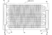
- FIG. 5 is a schematic diagram of a configuration of a plate fin tube type heat exchanger used for the heat source side heat exchanger 12, the load side heat exchanger 15 (15a to 15d), and the like.
- a plate fin tube type heat exchanger (12 or 15) transfers heat between the first connecting pipe 41, the second connecting pipe 42, the surrounding heat medium such as air, and the internal refrigerant.
- a heat tube 43, fins 44, a first distributor 45 and a second distributor 46 are provided.
- the configuration of the heat exchanger (12 or 15) will be described in more detail.
- the heat exchanger (12 or 15) has a configuration in which a plurality of fins 44 are arranged at intervals, and a plurality of heat transfer tubes 43 are arranged through the plurality of fins 44.
- One end of both ends of the plurality of heat transfer tubes 43 is connected to the first distribution unit 45, and the other end is connected to the second distribution unit 46.
- a first connection pipe 41 and a second connection pipe 42 that serve as refrigerant inlets and outlets from other devices in the refrigeration cycle are connected to the first distribution unit 45 and the second distribution unit 45.
- the 1st distribution part 45 and the 2nd distribution part 46 are parts which distribute the refrigerant
- the solid line arrow indicates the direction of refrigerant flow when the heat exchanger (12 or 15) acts as a condenser, and the broken line arrow indicates that the heat exchanger (12 or 15) acts as an evaporator.
- the direction in which the refrigerant flows is shown. This also applies to FIGS. 7 and 8 described later.
- a high-temperature and high-pressure gas refrigerant flows into the heat exchanger (12 or 15).
- the high-temperature and high-pressure gas refrigerant that has flowed into the heat exchanger (12 or 15) is condensed and liquefied through a two-phase region that is a mixed state of gas and liquid to become a high-temperature and high-pressure liquid refrigerant. Or it flows out of 15).
- the heat exchanger (12 or 15) acts as an evaporator
- a low-temperature and low-pressure two-phase refrigerant having low dryness flows into the heat exchanger (12 or 15) and evaporates, and the dryness is high. It becomes a two-phase refrigerant or a gas refrigerant and flows out of the heat exchanger (12 or 15).
- the heat exchanger (12 or 15) is usually subjected to groove processing on the inner surface (heat transfer surface) of the heat transfer tube 43 in order to promote heat transfer of the refrigerant flowing inside the heat transfer tube 43 and improve the heat transfer rate. Has been.
- FIG. 6 is a schematic cross-sectional view of a configuration example in which grooving is performed on the inner surface (heat transfer surface) of the heat transfer tube used in the heat exchanger of the refrigeration cycle apparatus according to Embodiment 1 of the present invention.
- a flow path 49 through which a refrigerant flows.
- a plurality of grooves 50 extending in the tube axis direction are formed at intervals in the circumferential direction, and the inner surface of the heat transfer tube 43 is an uneven surface 50a.
- the groove 50 is formed on the inner surface of the heat transfer tube 43 to form the uneven surface 50a, the boundary layer of the refrigerant is disturbed due to the uneven surface 50a, and the degree of disturbance of the refrigerant increases.
- the refrigerant increases in flow velocity in the concave portion 50b of the uneven surface 50a in the heat transfer tube 43, and flows through the heat transfer tube 43 while repeatedly colliding with the convex portion 50c. Therefore, generally, when the groove processing is performed on the inner surface of the heat transfer tube 43, not only the heat transfer rate increases, but also the pressure loss of the refrigerant increases. Thus, the groove 50 of the heat transfer tube 43 of the heat exchanger (12 or 15) may cause a disproportionation reaction for the refrigerant.
- the groove 50 of the heat transfer tube 43 is often formed into a shape (for example, a spiral extending in the tube axis direction) that has a large effect of disturbing the refrigerant flow. In this case, the effect is further increased. Note that FIG.
- the groove 50 may not be spiral, and the uneven surface 50a is formed inside the heat transfer tube 43, so that the refrigerant As long as the flow is turbulent, the same situation will occur regardless of the shape.
- the collision energy between the refrigerant and the convex portion 50c of the concave / convex surface 50a on the inner surface of the heat exchanger (12 or 15) can be obtained by Expression (1).
- high-temperature and high-pressure gas refrigerant flows into the heat transfer pipe 43 from the first connection pipe 41 through the first distribution header 47.
- the high-temperature and high-pressure gas refrigerant that has flowed into the heat transfer tube 43 is in a mixed state of gas and liquid by exchanging heat with a heat medium such as ambient air by the effect of the fins 44 inside the heat transfer tube 43. It liquefies through a two-phase region and becomes a high-temperature and high-pressure liquid refrigerant.
- the high-temperature and high-pressure liquid refrigerant flows out from the second connection pipe 42 via the second distribution header 48.
- a low-temperature and low-pressure two-phase refrigerant having a low dryness flows into the heat transfer pipe 43 from the second connection pipe 42 via the second distribution header 48.
- the low-temperature and low-pressure two-phase refrigerant that has flowed into the heat transfer tube 43 is heat-exchanged with the heat medium such as ambient air by the effect of the fins 44 inside the heat transfer tube 43, evaporates, and the low-temperature and low-pressure refrigerant. It becomes a two-phase refrigerant with a high degree of dryness or a low-temperature and low-pressure gas refrigerant.
- the low-temperature and low-pressure two-phase refrigerant or the low-temperature and low-pressure gas refrigerant flows out from the first connection pipe 41 through the first distribution header 47.
- the first connection pipe 41 and the second connection pipe 42 are connection pipes for connecting the heat exchanger (12 or 15) to other equipment, and use smooth pipes (circular pipes) having smooth inner surfaces.
- the magnitude relationship of the density of the refrigerant according to the state of the refrigerant is as follows. ⁇ High-pressure refrigerant> Low-pressure refrigerant ⁇ Liquid refrigerant> Gas refrigerant, two-phase refrigerant ⁇ Two-phase refrigerant with low dryness> Two-phase refrigerant with high dryness
- the pipe through which the liquid refrigerant flows can be thinner than the pipe through which the gas refrigerant flows.
- the pipe through which the two-phase refrigerant having a low dryness flows can be made thinner than the pipe through which the refrigerant having a high dryness flows.
- the refrigerant passing through the first connection pipe 41 is “a high-temperature / high-pressure gas refrigerant” or “a low-temperature / low-pressure two-phase refrigerant or a low-temperature / low-pressure gas refrigerant having a high degree of dryness”.
- the refrigerant passing through the pipe 42 is “a high-temperature / high-pressure liquid refrigerant” or “a low-temperature / low-pressure refrigerant having a low dryness”. Therefore, in consideration of pressure loss, a pipe that is thinner than the first connection pipe 41 is usually used for the second connection pipe 42. In some cases, the use of pipes of the same thickness may mean the commonality of components.
- the second connection pipe 42 is not made thinner than the first connection pipe 41, but the first connection pipe 41 and The second connection pipe 42 may be a pipe having the same thickness.
- a plurality of heat transfer tubes 43 are connected to the first connection tube 41 and the second connection tube 42, and 1 Often, one heat exchanger (12 or 15) is constructed.
- the refrigerant disproportionation reaction may occur. It becomes easy to get up.
- the total cross-sectional area of the inner cross-sectional areas of the heat transfer tubes 43 in each path is smaller than the inner cross-sectional area of the first connection tube 41 or the inner cross-sectional area of the second connection tube 42, the first connection tube 41 or the second connection tube 41.
- the speed of the refrigerant inside the heat transfer pipe 43 is faster than the speed of the refrigerant inside the connection pipe 42.
- the total cross-sectional area of the inner cross-sectional area of the heat transfer tube 43 in each path is larger than both the inner cross-sectional area of the first connecting pipe 41 and the inner cross-sectional area of the second connecting pipe 42, Leveling reaction is difficult to occur. That is, the total cross-sectional area of the inner cross-sectional areas of the heat transfer tubes 43 in each path is the same for the thicker one of the first connection tube 41 and the second connection tube 42 or the first connection tube 41 and the second connection tube 42. In the case of the thickness, if both are larger than the inner cross-sectional area of the connecting pipe, disproportionation reaction hardly occurs. However, even if the total cross-sectional area of the inner cross-sectional areas of the heat transfer tubes 43 in each pass is not increased so much, the disproportionation reaction can be made difficult to occur by using the following relationship.
- the refrigerant state in which disproportionation reaction is likely to occur is arranged, it is a liquid state and a two-phase state with a low dryness as described above. And since the refrigerant
- the first connecting pipe 41 is narrower than the first connecting pipe 41.
- the refrigerant in a refrigerant state in which a disproportionation reaction easily occurs passes through a narrowly configured pipe (a transmission line connected to the second connection pipe 42 via the second connection pipe 42 or the second distributor 46). That is, the heat pipe 43).
- the total cross-sectional area of the inner cross-sectional areas of the heat transfer tubes 43 of each path is the smaller of the inner cross-sectional area of the first connection pipe 41 and the inner cross-sectional area of the second connection pipe 42, that is, the first If the inner cross-sectional area of the two connecting pipes 42 is larger, the disproportionation reaction hardly occurs.
- the diameter of the first connecting pipe 41 and the diameter of the refrigerant pipe connected to the first connecting pipe 41 from the outside are substantially the same, and the diameter of the second connecting pipe 42 and the second connecting pipe are the same.
- the diameters of the refrigerant pipes connected to 42 from the outside are substantially the same. Therefore, the configuration in which the total sectional area of the inner sectional areas of the heat transfer tubes 43 in each path is larger than the inner sectional area of at least one of the first connecting pipe 41 and the second connecting pipe 42 is as follows. In other words. That is, the total sectional area of the inner sectional areas of the heat transfer tubes 43 in each path is larger than the inner sectional area of the refrigerant pipe connected from the outside to at least one of the first connecting pipe 41 and the second connecting pipe 42. In other words, the structure can be enlarged.
- the path is divided into four paths, and the four heat transfer tubes 43 are connected to the first connection tube 41 and the second connection tube 42 via the first distribution unit 45 and the second distribution unit 46.
- one heat exchanger (12 or 15) is configured. Therefore, the total cross-sectional area of the inner cross-sectional areas of the four heat transfer tubes 43 is the smaller of the inner cross-sectional area of the first connecting pipe 41 and the inner cross-sectional area of the second connecting pipe 42, that is, the second connecting pipe 42. If it is larger than the inner cross-sectional area, the disproportionation reaction hardly occurs.
- the second distribution unit 46 has a path number greater than 1.2, which is a value obtained by dividing the inner cross-sectional area of the second connection pipe 42 by the inner cross-sectional area of the heat transfer pipe 43, that is, the number of paths of 2 or more in the integer. If the distribution is performed in (3), the total sectional area of the inner sectional areas of the heat transfer tubes 43 is larger than the inner sectional area of the second connection tube 42.
- the number of passes greater than 3.3 which is a value obtained by dividing the inner cross-sectional area of the second connection tube 42 by the inner cross-sectional area of the heat transfer tube 43, that is, an integer.
- the number of passes is four or more, and the second distribution part 46 distributes the total cross-sectional area of the heat transfer tube 43, the total cross-sectional area becomes larger than the inner cross-sectional area of the second connection tube 42, and disproportionation occurs. The reaction is difficult to occur.
- the inner diameter of the heat transfer tube 43 means a diameter (d in FIG. 6) based on the recess 50b of the uneven surface 50a of the heat transfer tube 43.
- the inner diameter of the heat transfer tube 43 means the diameter of a circle inscribed in the bottom surface of the plurality of recesses 50b.
- the inner cross-sectional area of the heat transfer tube 43 corresponds to the area of a circle whose diameter is the diameter (d in FIG. 6) with respect to the recess 50b of the uneven surface 50a of the heat transfer tube 43.
- FIG. 5 shows a case where four heat transfer tubes 43 are connected to the first connection tube 41 and the second connection tube 42 to constitute one heat exchanger (12 or 15).
- the number of passes of the heat transfer tubes 43 constituting one heat exchanger is not limited to four.
- one heat transfer tube 43 may be connected to the first connection tube 41 and the second connection tube 42 to form one heat exchanger (12 or 15).
- the inner cross-sectional area of one heat transfer tube 43 is the smaller of the inner cross-sectional area of the first connection tube 41 and the inner cross-sectional area of the second connection tube 42, that is, the second connection tube 42. The disproportionation reaction is unlikely to occur if the inner cross-sectional area is larger.
- FIG. 7 is a schematic diagram of another configuration of the heat exchanger of the refrigeration cycle apparatus according to Embodiment 1 of the present invention.
- the heat exchanger (12 or 15) of FIG. 7 has a configuration in which each of the first distribution unit 45 and the second distribution unit 46 includes a plurality of distribution headers.
- the first distribution unit 45 includes a first distribution header 47a and a first distribution header 47b.
- the first connection pipe 41 is branched into two, which is the same as the number of distribution headers, one connected to the first distribution header 47a and the other connected to the first distribution header 47b.
- Each of the first distribution header 47 a and the first distribution header 47 b is connected to the two heat transfer tubes 43.
- the second distribution unit 46 has a second distribution header 48a and a second distribution header 48b.
- the second connection pipe 42 is branched into two, which is the same as the number of distribution headers, one connected to the second distribution header 48a and the other connected to the second distribution header 48b.
- Each of the second distribution header 47 a and the second distribution header 47 b is connected to the two heat transfer tubes 43.
- the first connection pipe 41 and the second connection pipe 42 are branched into a plurality (here, two) by the first distribution section 45 and the second distribution section 46, and each is a separate heat transfer pipe 43. Even if the heat exchanger structure is connected to, the disproportionation reaction is unlikely to occur if the configuration is the same as described above with respect to the inner area.
- each of the first distribution unit 45 and the second distribution unit 46 divides the flow path into two, and each is connected to two heat transfer tubes 43. It is a configuration.
- the total inner sectional area of the inner sectional areas of the four heat transfer tubes 43 is the smaller of the inner sectional area of the first connecting pipe 41 and the inner sectional area of the second connecting pipe 42, that is, the second connection. If it is configured to be larger than the inner cross-sectional area of the tube 42, the disproportionation reaction hardly occurs.
- FIG. 8 is a schematic diagram of another configuration of the heat exchanger of the refrigeration cycle apparatus according to Embodiment 1 of the present invention.
- the heat exchanger (12 or 15) in FIG. 8 is a so-called 1-2-pass heat exchanger in which the number of passes changes in the flow path.
- the first connection pipe 41 is connected to the first distribution header 47, and the first distribution header 47 is branched into six paths, and merges every two paths in the middle, thereby halving the number of paths.
- the second connection pipe 42 is connected to the second distribution header 48, and the second distribution header 48 is connected to the three heat transfer pipes 43. That is, the number of paths of the heat transfer tubes 43 connected to the first connection pipe 41 via the first distribution section 45 is six, and the number of paths of the heat transfer tubes 43 connected to the second connection pipe 42 via the second distribution section 46 is The number of passes is three.
- the following configuration is desirable. That is, of the first connection pipe 41 side and the second connection pipe 42 side, the total cross-sectional area of the inner cross-sectional areas of the three heat transfer tubes 43 on the second connection pipe 42 side where the number of passes is small is determined as the first connection pipe 41. If the smaller one of the inner cross-sectional area of the second connecting pipe 42 and the inner cross-sectional area of the second connecting pipe 42, that is, the inner cross-sectional area of the second connecting pipe 42, it is possible to make the disproportionation reaction difficult to occur. .
- the disproportionation reaction with a larger number of passes can be suppressed, and there is some effect. That is, of the first connection pipe 41 side and the second connection pipe 42 side, the total cross-sectional area of the inner cross-sectional areas of the six heat transfer pipes 43 on the first connection pipe 41 side having a large number of passes is the first connection pipe 41. If the inner cross-sectional area of the second connecting pipe 42 is smaller than the inner cross-sectional area of the second connecting pipe 42, that is, the inner cross-sectional area of the second connecting pipe 42, the non-uniformity in the larger number of passes. The reaction can be suppressed and has a certain effect.
- FIG. 9 is a schematic diagram of another heat transfer tube used in the heat exchanger of the refrigeration cycle apparatus according to Embodiment 1 of the present invention.
- FIG. 9 shows a flat tube having a flat channel structure in which the inside is divided into a plurality of (here, four) channels 49.
- the total sum of the cross-sectional areas of the respective flow paths 49 inside the single heat transfer tube 43 is considered in considering the above-described configuration in which disproportionation reaction hardly occurs.
- the cross-sectional area is treated as the inner cross-sectional area of one heat transfer tube 43. A specific example will be described below.
- the case where the inner cross-sectional areas of all the flow paths 49 in the heat transfer tube 43 are the same has been described as an example, but the present invention is not limited to this, and the internal cross-sectional areas of some of the flow paths 49 are broken.
- the areas may be different.
- the inner cross-sectional areas of the two flow paths 49 at both ends may be different from the inner cross-sectional areas of the other flow paths 49.
- the total cross-sectional area of the inner cross-sectional areas of the respective flow passages 49 of the heat transfer tubes 43 of each path is smaller than the inner cross-sectional area of the first connecting pipe 41 and the inner cross-sectional area of each second connecting pipe 42.
- it is configured to be larger than the inner cross-sectional area of each second connecting pipe 42, the disproportionation reaction hardly occurs.
- the flow path 49 is not circular but has a flat shape such as a rectangle.
- the inner cross-sectional area of the flow path 49 is calculated on the basis of the recess 50b of the uneven surface 50a provided on each flat heat transfer surface. That is, the cross-sectional area of the flow path 49 is calculated as a flat inner cross section inscribed in the bottom surface of each recess 50b.
- FIG. 10 is a schematic diagram of another configuration of the heat exchanger of the refrigeration cycle apparatus according to Embodiment 1 of the present invention.
- the heat exchanger (12 or 15) of FIG. 10 includes a distributor 52 and a distribution capillary 51 as the second distributor 46 which is an inlet side distributor when the heat exchanger (12 or 15) acts as an evaporator. (51a to 51d) is used.
- One end of the distribution capillary 51 (51a to 51d) is connected to the heat transfer tube 43, and the other end is connected to the distributor 52.
- the second connecting pipe 42 is connected to the distributor 52.
- the refrigerant is in a two-phase state at the inlet of the evaporator, it is possible to distribute more uniformly through the distribution capillary 51 in this way, and heat exchange performance is improved.
- the distribution capillary 51 (51a to 51d) uses a pipe having an inner diameter smaller than that of the heat transfer tube 43, there is a concern that a disproportionation reaction of the refrigerant may occur in the distribution capillary 51 (51a to 51d). It is.
- the total cross-sectional area of the inner cross-sectional area of the heat transfer tube 43 of each path of the heat exchanger (12 or 15) is set to the inner cross-sectional area of the first connection tube 41 and the second connection tube 42.
- the diameter of the heat transfer tube 43 is based on the concave portion 50b of the uneven surface 50a of the heat transfer tube 43 (FIG. 6).
- the diameter based on the convex portion 50c of the concave-convex surface 50a of the heat transfer tube 43 may be used.
- the diameter based on the convex portion 50c of the concave and convex surface 50a of the heat transfer tube 43 corresponds to the diameter of a circle inscribed in the upper surface of the plurality of convex portions 50c.
- the height of the convex portion 50c is ⁇ . It corresponds to d-2 ⁇ ⁇ .
- the “total cross-sectional area of the inner cross-sectional area of the heat transfer tube 43 in each path” calculated using “d ⁇ 2 ⁇ ⁇ ” as the diameter of the heat transfer tube 43 is the inner cross-sectional area of the first connection pipe 41 and the second cross-sectional area.
- the inner cross-sectional area of the flow path 49 is calculated as a flat inner cross-section inscribed in the bottom surface of each concave portion 50b.
- the flat inner cross-sectional area inscribed in the upper surface of each convex portion 50c is calculated. You may make it do.
- the inner cross-sectional area corresponding to one flow path 49 is calculated as a flat inner cross-sectional area inscribed in the upper surface of each convex portion 50c, and the calculation result is used to calculate “inside of the heat transfer tube 43 in each path.
- the effect of suppressing the disproportionation reaction can be further increased as compared with the case where the inner cross-sectional area for one channel 49 is calculated as a flat inner cross-section inscribed in the bottom surface of each recess 50b.
- the unevenness is formed only on some part of the heat transfer surface. Even when a heat transfer promotion mechanism such as the surface 50a is provided, it leads to a disproportionation reaction of the refrigerant. For this reason, if it is set as said structure, the same effect is acquired.
- the uneven surface 50a as an example of the heat transfer promotion mechanism which accelerates
- the heat transfer tube 43 itself may be a smooth tube (circular tube) having a smooth inner surface, and may be configured to include other heat transfer promotion mechanisms such as inserting a helically formed torsion tube inside the heat transfer tube 43. . In this case as well, the same can be said and the same effect is obtained.
- the heat source side heat exchanger 12 or the load side heat exchanger 15 has been described as the heat exchanger having the structure described above with reference to the drawings.
- the heat source side heat exchanger 12 and the load side heat exchanger Of course, both of the exchangers 15 may be heat exchangers having the structure described above with reference to the drawings.
- the refrigeration cycle apparatus 100 has several operation modes. In these operation modes, the refrigerant flows through the extension pipe 4 that connects the outdoor unit 1 and the indoor unit 2.
- the high pressure detection device 37 and the low pressure detection device 38 are installed to control the refrigeration cycle high pressure and low pressure to target values, but may be a temperature detection device that detects a saturation temperature.
- coolant flow path switching device 11 was shown as if it were a four-way valve, it is not restricted to this, It uses the two-way flow path switching valve and the three-way flow path switching valve similarly, You may comprise so that a refrigerant
- the heat source side heat exchanger 12 and the load side heat exchangers 15a to 15d are provided with a blower, and in many cases, condensation or evaporation is promoted by blowing, but this is not restrictive.
- a blower for example, as the load side heat exchangers 15a to 15d, a panel heater using radiation can be used, and as the heat source side heat exchanger 12, a water-cooled type that moves heat by water or antifreeze. Things can also be used. Any heat exchanger having a structure capable of radiating or absorbing heat can be used.
- the indoor unit 2 can arbitrarily select one of a cooling operation and a heating operation, and the entire system can perform a mixed operation of the indoor unit 2 that performs the cooling operation and the indoor unit 2 that performs the heating operation.
- the present invention can also be applied to a refrigeration cycle apparatus and has the same effect.
- FIG. A second embodiment of the present invention will be described with reference to the drawings. In the following, the second embodiment will be described focusing on the differences from the first embodiment. Note that the modification applied in the configuration part of the first embodiment is also applied to the same configuration part of the second embodiment.
- FIG. 11 is a schematic diagram of a configuration of a plate heat exchanger of the refrigeration cycle apparatus according to Embodiment 2 of the present invention.
- the plate fin tube type heat exchanger shown in the first embodiment is used, but when the heat medium that exchanges heat with the refrigerant is water or brine, the plate Often a heat exchanger of the type is used.
- the plate-type heat exchanger a plurality of plates 53 are stacked, and a flow path 49 is formed between the plates 53. The refrigerant and the heat medium alternately flow through the flow paths 49, so that the refrigerant and the heat The medium exchanges heat with the medium.
- the first connecting pipe 41 and the second connecting pipe 42 are connected to a flow path 49 between the plates 53, and the heat medium flows in from the heat medium inlet 54 and flows out from the heat medium outlet 55.
- a groove 50A is provided on the surface of the plate 53, which is a heat transfer surface of the plate heat exchanger, and an uneven surface 50a is formed as a heat transfer promotion mechanism for promoting heat transfer.
- the shape of the groove 50A is various, but the shape is different from the groove 50 in the heat transfer tube 43 in the case of a plate fin tube type heat exchanger. However, it is the same in that the grooves are provided to disturb the flow of the refrigerant and improve the heat transfer coefficient, and the same can be said for the first embodiment. Therefore, as in the first embodiment, the “total sectional area of the cross-sectional areas of each flow path 49” is smaller than the smaller of the inner sectional area of the first connecting pipe 41 and the inner sectional area of the second connecting pipe 42. If it is too large, the disproportionation reaction of the refrigerant does not occur easily. Of course, there is no problem even if the inner cross-sectional area of the first connecting pipe 41 and the inner cross-sectional area of the second connecting pipe 42 are the same.
- the “total cross-sectional area of the cross-sectional area of each flow path 49” is obtained by multiplying the cross-sectional area obtained by multiplying the distance between the plates 53 and the width of the plate 53 (W dimension in FIG. 11) by the plate This is equivalent to a value obtained by multiplying the number of the flow paths 49 through which the refrigerant flows between 53.
- n plates 53 and the flow path 49 through which the refrigerant flows and the flow path through which the heat medium flows are “(n ⁇ 1) / 2” respectively, “distance between the plates 53” ⁇ “width of the plate 53 " ⁇ ” (n-1) / 2 "corresponds to” the total cross-sectional area of the cross-sectional areas of the respective channels 49 ". If this value is larger than the smaller one of the inner cross-sectional area of the first connecting pipe 41 and the inner cross-sectional area of the second connecting pipe 42, the disproportionation reaction of the refrigerant does not easily occur.
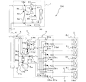
- FIG. 12 is a circuit diagram of a refrigeration cycle apparatus according to Embodiment 2 of the present invention.
- a refrigeration cycle apparatus 100 shown in FIG. 12 includes a refrigerant circulation circuit A in which an outdoor unit 1 and a heat medium relay unit 3 as a relay are connected by an extension pipe 4 so that a refrigerant circulates.
- the refrigeration cycle apparatus 100 includes a heat medium circulation circuit B in which the heat medium converter 3 and the indoor unit 2 are connected by a pipe (heat medium pipe) 5 and a heat medium such as water or brine circulates.
- the heat medium relay unit 3 includes a load side heat exchanger 15a and a load side heat exchanger 15b that perform heat exchange between the refrigerant circulating in the refrigerant circuit A and the heat medium circulating in the heat medium circuit B.
- the heat medium relay unit 3 is located separately from the outdoor unit 1 and the indoor unit 2, for example, a ceiling that is inside the building 9 but separate from the indoor space 7 as shown in FIG. 1. It is installed in a space such as the back (hereinafter simply referred to as space 8).
- the heat medium relay 3 can also be installed in a common space where there is an elevator or the like.
- the operation mode executed by the refrigeration cycle apparatus 100 includes a cooling only operation mode in which all the driven indoor units 2 execute a cooling operation and a heating operation in which all the driven indoor units 2 execute a heating operation. There is an operation mode. Further, there are a cooling main operation mode executed when the cooling load is larger and a heating main operation mode executed when the heating load is larger.
- the high-temperature and high-pressure gas refrigerant discharged from the compressor 10 flows into the heat source side heat exchanger 12 via the first refrigerant flow switching device 11 and dissipates heat to the surrounding air. It condenses and becomes high-pressure liquid refrigerant and flows out of the outdoor unit 1 through the check valve 13a. Then, it flows into the heat medium relay unit 3 through the extension pipe 4. The refrigerant flowing into the heat medium relay unit 3 passes through the opening / closing device 17a, expands in the expansion device 16a and the expansion device 16b, and becomes a low-temperature and low-pressure two-phase refrigerant.
- the two-phase refrigerant flows into each of the load side heat exchanger 15a and the load side heat exchanger 15b acting as an evaporator, absorbs heat from the heat medium circulating in the heat medium circuit B, and becomes a low-temperature and low-pressure gas refrigerant. .
- the gas refrigerant flows out of the heat medium relay unit 3 via the second refrigerant flow switching device 18a and the second refrigerant flow switching device 18b. Then, it flows into the outdoor unit 1 again through the extension pipe 4.
- the refrigerant flowing into the outdoor unit 1 passes through the check valve 13d and is sucked into the compressor 10 again via the first refrigerant flow switching device 11 and the accumulator 19.
- the heat medium is cooled by the refrigerant in both the load side heat exchanger 15a and the load side heat exchanger 15b.
- the cooled heat medium flows through the pipe 5 by the pump 21a and the pump 21b.
- the heat medium flowing into the use side heat exchangers 26a to 26d through the second heat medium flow switching devices 23a to 23d absorbs heat from the indoor air.
- the indoor air is cooled to cool the indoor space 7.
- the refrigerant that has flowed out of the use side heat exchangers 26a to 26d flows into the heat medium flow control devices 25a to 25d, passes through the first heat medium flow switching devices 22a to 22d, and passes through the load side heat exchanger 15a and the load side.
- the heat medium flow control devices 25a to 25d corresponding to the use side heat exchangers 26a to 26d without heat load are fully closed. Further, the heat medium flow control devices 25a to 25d corresponding to the use side heat exchangers 26a to 26d having the heat load adjust the opening degree to adjust the heat load in the use side heat exchangers 26a to 26d.
- the high-temperature and high-pressure gas refrigerant discharged from the compressor 10 flows out of the outdoor unit 1 through the first refrigerant flow switching device 11 and the first connection pipe 4a and the check valve 13b. To do. Then, it flows into the heat medium relay unit 3 through the extension pipe 4.
- the refrigerant that has flowed into the heat medium relay unit 3 flows into the load-side heat exchanger 15a and the load-side heat exchanger 15b through the second refrigerant flow switching device 18a and the second refrigerant flow switching device 18b, respectively.
- the heat is radiated to the heat medium circulating in the heat medium circuit B, and becomes a high-pressure liquid refrigerant.
- the high-pressure liquid refrigerant expands in the expansion device 16a and the expansion device 16b to become a low-temperature and low-pressure two-phase refrigerant, and flows out of the heat medium converter 3 through the opening / closing device 17b. Then, it flows into the outdoor unit 1 again through the extension pipe 4.
- the refrigerant flowing into the outdoor unit 1 passes through the second connection pipe 4b and the check valve 13c, flows into the heat source side heat exchanger 12 acting as an evaporator, absorbs heat from the surrounding air, and is a low-temperature and low-pressure gas refrigerant. It becomes.
- the gas refrigerant is again sucked into the compressor 10 via the first refrigerant flow switching device 11 and the accumulator 19.
- the operation of the heat medium in the heat medium circuit B is the same as in the cooling only operation mode.
- the heat medium is heated by the refrigerant in the load-side heat exchanger 15a and the load-side heat exchanger 15b, and is radiated to the indoor air in the use-side heat exchanger 26a and the use-side heat exchanger 26b.
- the indoor space 7 is heated.
- the high-temperature and high-pressure gas refrigerant discharged from the compressor 10 flows into the heat source side heat exchanger 12 via the first refrigerant flow switching device 11 and radiates and condenses to the surrounding air. Then, it becomes a two-phase refrigerant and flows out of the outdoor unit 1 through the check valve 13a. Then, it flows into the heat medium relay unit 3 through the extension pipe 4. The refrigerant flowing into the heat medium relay unit 3 flows into the load-side heat exchanger 15b acting as a condenser through the second refrigerant flow switching device 18b, and dissipates heat to the heat medium circulating in the heat medium circuit B. And high pressure liquid refrigerant.
- the high-pressure liquid refrigerant expands in the expansion device 16b and becomes a low-temperature and low-pressure two-phase refrigerant.
- the two-phase refrigerant flows into the load-side heat exchanger 15a acting as an evaporator through the expansion device 16a, absorbs heat from the heat medium circulating in the heat medium circuit B, and becomes a low-pressure gas refrigerant. It flows out of the heat medium relay unit 3 through the path switching device 18a. Then, it flows into the outdoor unit 1 again through the extension pipe 4.
- the refrigerant flowing into the outdoor unit 1 passes through the check valve 13d and is sucked into the compressor 10 again via the first refrigerant flow switching device 11 and the accumulator 19.
- the heat of the refrigerant is transmitted to the heat medium by the load side heat exchanger 15b.
- the heated heat medium flows in the pipe 5 by the pump 21b.
- the heat medium that has flowed into the use side heat exchangers 26a to 26d for which heating is requested by operating the first heat medium flow switching devices 22a to 22d and the second heat medium flow switching devices 23a to 23d radiates heat to the indoor air.
- the indoor air is heated to heat the indoor space 7.
- the cold heat of the refrigerant is transmitted to the heat medium in the load side heat exchanger 15a.
- the cooled heat medium flows through the pipe 5 by the pump 21a.
- the heat medium that has flowed into the use side heat exchangers 26a to 26d for which cooling is requested by operating the first heat medium flow switching devices 22a to 22d and the second heat medium flow switching devices 23a to 23d absorbs heat from the indoor air. To do.
- the indoor air is cooled to cool the indoor space 7.
- the heat medium flow control devices 25a to 25d corresponding to the use side heat exchangers 26a to 26d without heat load are fully closed.
- the heat medium flow control devices 25a to 25d corresponding to the use side heat exchangers 26a to 26d having the heat load adjust the opening degree to adjust the heat load in the use side heat exchangers 26a to 26d.
- Heating main operation mode In the heating main operation mode, the high-temperature and high-pressure gas refrigerant discharged from the compressor 10 passes through the first refrigerant flow switching device 11, passes through the first connection pipe 4 a and the check valve 13 b, and then the outdoor unit 1. Spill from. Then, it flows into the heat medium relay unit 3 through the extension pipe 4. The refrigerant flowing into the heat medium relay unit 3 flows into the load-side heat exchanger 15b acting as a condenser through the second refrigerant flow switching device 18b, and dissipates heat to the heat medium circulating in the heat medium circuit B. And high pressure liquid refrigerant.
- the high-pressure liquid refrigerant expands in the expansion device 16b and becomes a low-temperature and low-pressure two-phase refrigerant.
- the two-phase refrigerant flows into the load-side heat exchanger 15a acting as an evaporator via the expansion device 16a, absorbs heat from the heat medium circulating in the heat medium circuit B, and passes through the second refrigerant flow switching device 18a. And flows out of the heat medium relay unit 3. Then, it flows into the outdoor unit 1 again through the extension pipe 4.
- the refrigerant flowing into the outdoor unit 1 flows into the heat source side heat exchanger 12 acting as an evaporator through the second connection pipe 4b and the check valve 13c, absorbs heat from the surrounding air, and is a low-temperature and low-pressure gas.
- the gas refrigerant is again sucked into the compressor 10 via the first refrigerant flow switching device 11 and the accumulator 19.
- the operation of the heat medium in the heat medium circuit B, the first heat medium flow switching devices 22a to 22d, the second heat medium flow switching devices 23a to 23d, the heat medium flow control devices 25a to 25d, and the use side The operations of the heat exchangers 26a to 26d are the same as those in the cooling main operation mode.
- the first heat medium flow switching device 22 corresponding to the use side heat exchanger 26 performing the heating operation and The second heat medium flow switching device 23 is switched to a flow path connected to the load side heat exchanger 15b for heating. Further, the first heat medium flow switching device 22 and the second heat medium flow switching device 23 corresponding to the use side heat exchanger 26 performing the cooling operation are connected to the cooling load side heat exchanger 15a. Switch to the flow path. For this reason, in each indoor unit 2, heating operation and cooling operation can be performed freely.
- the first heat medium flow switching device 22 and the second heat medium flow switching device 23 are those that can switch a three-way flow path such as a three-way valve, and those that open and close a two-way flow path such as an on-off valve. What is necessary is just to switch a flow path, such as combining two.
- the first heat medium can be obtained by combining two things such as a stepping motor drive type mixing valve that can change the flow rate of the three-way flow path and two things that can change the flow rate of the two-way flow path such as an electronic expansion valve.
- the flow path switching device 22 and the second heat medium flow path switching device 23 may be used.
- the heat medium flow control device 25 may be installed as a control valve having a three-way flow path with a bypass pipe that bypasses the use-side heat exchanger 26 other than the two-way valve. Further, the heat medium flow control device 25 may be a stepping motor drive type that can control the flow rate flowing through the flow path, and may be a two-way valve or a device in which one end of the three-way valve is closed. Further, as the heat medium flow control device 25, a device that opens and closes a two-way flow path such as an open / close valve may be used, and the average flow rate may be controlled by repeating ON / OFF.
- first refrigerant flow switching device 11 and the second refrigerant flow switching device 18 are shown as if they were four-way valves.
- the present invention is not limited to this, and a two-way flow switching valve or a three-way flow switching is possible. A plurality of valves may be used so that the refrigerant flows in the same manner.
- the heat medium flow control device 25 is built in the heat medium converter 3
- the heat medium flow control device 25 is not limited thereto, and may be built in the indoor unit 2. 3 and the indoor unit 2 may be configured separately.
- the heat medium for example, brine (antifreeze), water, a mixture of brine and water, a mixture of water and an additive having a high anticorrosive effect, or the like can be used. Therefore, in the refrigeration cycle apparatus 100, even if the heat medium leaks into the indoor space 7 through the indoor unit 2, a highly safe heat medium is used, which contributes to an improvement in safety. Become.
- the heat source side heat exchanger 12 and the use side heat exchangers 26a to 26d are provided with a blower, and in many cases, condensation or evaporation is promoted by blowing, but this is not restrictive.
- a blower for example, as the use side heat exchangers 26a to 26d, a panel heater using radiation can be used.
- a water-cooled type that moves heat by water or antifreeze can also be used. Any structure that can dissipate or absorb heat can be used.
- a water-cooled type heat exchanger 12 is used as the heat source side heat exchanger 12, the heat exchanger of FIG. 11 described in the second embodiment is used.
- a plate-type heat exchanger is used as the load-side heat exchanger 15
- it is not limited to a plate-type, but any type that can exchange heat between the refrigerant and the heat medium can be used. It may be anything.
- any type of heat source side heat exchanger may be used as long as it can exchange heat between the refrigerant and the heat medium. But you can.
- the number of pumps 21a and 21b is not limited to one, and a plurality of small capacity pumps may be arranged in parallel.
- the compressor 10, the four-way valve (first refrigerant flow switching device) 11, and the heat source side heat exchanger 12 are accommodated in the outdoor unit 1, and the use side heat exchanger is configured to exchange heat between the air in the air-conditioning target space and the refrigerant.
- 26 is accommodated in the indoor unit 2
- the load-side heat exchanger 15 and the expansion device 16 are accommodated in the heat medium converter 3
- the outdoor unit 1 and the heat medium converter 3 are connected by the extension pipe 4 to form a refrigerant. Is circulated, and the heat medium is circulated by connecting the indoor unit 2 and the heat medium converter 3 with a set of two pipes 5 each, and the load-side heat exchanger 15 exchanges heat between the refrigerant and the heat medium.
- the system to be performed has been described by way of an example of a system that can perform a mixed operation of the indoor unit 2 that performs the cooling operation and the indoor unit 2 that performs the heating operation, but is not limited thereto.
- the outdoor unit 1 and the heat medium relay unit 3 described in the first embodiment can be combined and applied to a system that performs only a cooling operation or a heating operation in the indoor unit 2 and has the same effect.
- Heat source unit (outdoor unit), 2, 2a, 2b, 2c, 2d indoor unit, 3 heat medium converter (relay unit), 4 extension pipe (refrigerant pipe), 4a first connection pipe, 4b second connection pipe, 5 piping (heat medium piping), 6 outdoor space, 7 indoor space, 8 outdoor space such as the back of the ceiling and indoor space, 9 building, 10 compressor, 11 1st refrigerant flow switching device (Four-way valve), 12 heat source side heat exchanger (first heat exchanger), 13a, 13b, 13c, 13d check valve, 15, 15a, 15b, 15c, 15d load side heat exchanger (second heat Exchanger), 16, 16a, 16b, 16c, 16d throttle device, 17a, 17b switching device, 18, 18a, 18b second refrigerant flow switching device, 19 accumulator, 21a, 21b pump, 22, 22a, 22b, 22 22d, first heat medium flow switching device, 23, 23a, 23b, 23c, 23d, second heat medium flow switching device, 25, 25a, 25
Landscapes
- Engineering & Computer Science (AREA)
- Physics & Mathematics (AREA)
- Thermal Sciences (AREA)
- General Engineering & Computer Science (AREA)
- Mechanical Engineering (AREA)
- Chemical & Material Sciences (AREA)
- Geometry (AREA)
- Chemical Kinetics & Catalysis (AREA)
- Combustion & Propulsion (AREA)
- Materials Engineering (AREA)
- Organic Chemistry (AREA)
- Analytical Chemistry (AREA)
- Power Engineering (AREA)
- Heat-Exchange Devices With Radiators And Conduit Assemblies (AREA)
Abstract
Priority Applications (4)
| Application Number | Priority Date | Filing Date | Title |
|---|---|---|---|
| US15/116,544 US20160341453A1 (en) | 2014-03-17 | 2014-03-17 | Refrigeration cycle apparatus |
| JP2016508346A JPWO2015140886A1 (ja) | 2014-03-17 | 2014-03-17 | 冷凍サイクル装置 |
| EP14886650.2A EP3121538A1 (fr) | 2014-03-17 | 2014-03-17 | Appareil à cycle frigorifique |
| PCT/JP2014/057049 WO2015140886A1 (fr) | 2014-03-17 | 2014-03-17 | Appareil à cycle frigorifique |
Applications Claiming Priority (1)
| Application Number | Priority Date | Filing Date | Title |
|---|---|---|---|
| PCT/JP2014/057049 WO2015140886A1 (fr) | 2014-03-17 | 2014-03-17 | Appareil à cycle frigorifique |
Publications (1)
| Publication Number | Publication Date |
|---|---|
| WO2015140886A1 true WO2015140886A1 (fr) | 2015-09-24 |
Family
ID=54143912
Family Applications (1)
| Application Number | Title | Priority Date | Filing Date |
|---|---|---|---|
| PCT/JP2014/057049 Ceased WO2015140886A1 (fr) | 2014-03-17 | 2014-03-17 | Appareil à cycle frigorifique |
Country Status (4)
| Country | Link |
|---|---|
| US (1) | US20160341453A1 (fr) |
| EP (1) | EP3121538A1 (fr) |
| JP (1) | JPWO2015140886A1 (fr) |
| WO (1) | WO2015140886A1 (fr) |
Cited By (7)
| Publication number | Priority date | Publication date | Assignee | Title |
|---|---|---|---|---|
| CN106440435A (zh) * | 2016-10-27 | 2017-02-22 | 南京天加空调设备有限公司 | 一种轨道交通行业用双机头冷水机组 |
| WO2017187519A1 (fr) * | 2016-04-26 | 2017-11-02 | 三菱電機株式会社 | Compresseur et dispositif à cycle de réfrigération |
| JP2018025326A (ja) * | 2016-08-09 | 2018-02-15 | パナソニックIpマネジメント株式会社 | 冷凍サイクル装置 |
| JP2018124046A (ja) * | 2017-02-03 | 2018-08-09 | 三星電子株式会社Samsung Electronics Co.,Ltd. | 空気調和装置 |
| JP6641542B1 (ja) * | 2019-03-05 | 2020-02-05 | 三菱電機株式会社 | 熱交換器及び冷凍サイクル装置 |
| JP6644194B1 (ja) * | 2019-01-21 | 2020-02-12 | 三菱電機株式会社 | 室外機及び空気調和装置 |
| JP2020046173A (ja) * | 2019-12-24 | 2020-03-26 | 三菱電機株式会社 | 室外機及び冷凍サイクル装置 |
Families Citing this family (8)
| Publication number | Priority date | Publication date | Assignee | Title |
|---|---|---|---|---|
| FI10540U1 (fi) * | 2013-04-11 | 2014-07-11 | Vacon Oyj | Nestejäähdytysjärjestely |
| CN103759455B (zh) * | 2014-01-27 | 2015-08-19 | 青岛海信日立空调系统有限公司 | 热回收变频多联式热泵系统及其控制方法 |
| JP6721546B2 (ja) * | 2017-07-21 | 2020-07-15 | ダイキン工業株式会社 | 冷凍装置 |
| EP3889512A1 (fr) * | 2017-09-29 | 2021-10-06 | Daikin Industries, Ltd. | Système de climatisation |
| JP7341326B2 (ja) * | 2020-04-07 | 2023-09-08 | 三菱電機株式会社 | 冷凍サイクル装置 |
| EP4357714A1 (fr) * | 2022-10-21 | 2024-04-24 | Siemens Gamesa Renewable Energy A/S | Dispositif de transfert de chaleur |
| DE102023102779A1 (de) * | 2023-02-06 | 2024-08-08 | Viessmann Climate Solutions Se | Wärmeübertrager |
| CN121039393A (zh) * | 2023-05-23 | 2025-11-28 | 维斯塔斯风力系统有限公司 | 与冷却风力涡轮机有关的改进 |
Citations (7)
| Publication number | Priority date | Publication date | Assignee | Title |
|---|---|---|---|---|
| JP2007263492A (ja) * | 2006-03-29 | 2007-10-11 | Sanyo Electric Co Ltd | 冷媒サイクル装置 |
| JP2009257741A (ja) * | 2008-03-25 | 2009-11-05 | Daikin Ind Ltd | 冷凍装置 |
| WO2010050002A1 (fr) * | 2008-10-29 | 2010-05-06 | 三菱電機株式会社 | Climatiseur |
| JP2011257111A (ja) * | 2010-06-11 | 2011-12-22 | Showa Denko Kk | エバポレータ |
| JP2012505296A (ja) * | 2008-10-10 | 2012-03-01 | イー・アイ・デュポン・ドウ・ヌムール・アンド・カンパニー | 2,3,3,3−テトラフルオロプロペン、2−クロロ−2,3,3,3−テトラフルオロプロパノール、2−クロロ−2,3,3,3−テトラフルオロ酢酸プロピルまたは(2−クロロ−2,3,3,3−テトラフルオロプロポキシ)塩化亜鉛を含む組成物 |
| JP2012131994A (ja) * | 2010-11-30 | 2012-07-12 | Jx Nippon Oil & Energy Corp | 冷凍機用作動流体組成物および冷凍機油 |
| WO2012157764A1 (fr) * | 2011-05-19 | 2012-11-22 | 旭硝子株式会社 | Fluide moteur, et système à cycle thermique |
Family Cites Families (11)
| Publication number | Priority date | Publication date | Assignee | Title |
|---|---|---|---|---|
| JPH10122704A (ja) * | 1996-10-23 | 1998-05-15 | Toshiba Corp | 空気調和装置の熱交換器 |
| JP3811909B2 (ja) * | 1997-03-21 | 2006-08-23 | 三菱電機株式会社 | 伝熱管およびそれを用いた熱交換器 |
| US6223549B1 (en) * | 1998-04-24 | 2001-05-01 | Mitsubishi Denki Kabushiki Kaisha | Refrigeration cycle device, a method of producing the device, and a method of operating the device |
| JP2001248941A (ja) * | 1999-12-28 | 2001-09-14 | Daikin Ind Ltd | 冷凍装置 |
| WO2006042015A1 (fr) * | 2004-10-07 | 2006-04-20 | Brooks Automation, Inc. | Echangeur de chaleur efficace pour procede de refrigeration |
| JP2010019489A (ja) * | 2008-07-10 | 2010-01-28 | Sumitomo Light Metal Ind Ltd | 蒸発器用の内面溝付伝熱管 |
| JP5370400B2 (ja) * | 2010-04-28 | 2013-12-18 | ダイキン工業株式会社 | 熱交換装置 |
| JP2012167913A (ja) * | 2011-02-17 | 2012-09-06 | Hitachi Appliances Inc | 空気調和機 |
| JP2012167912A (ja) * | 2011-02-17 | 2012-09-06 | Hitachi Appliances Inc | 空気調和機 |
| JP6065429B2 (ja) * | 2011-12-08 | 2017-01-25 | パナソニック株式会社 | 空気調和機 |
| JP5536817B2 (ja) * | 2012-03-26 | 2014-07-02 | 日立アプライアンス株式会社 | 冷凍サイクル装置 |
-
2014
- 2014-03-17 EP EP14886650.2A patent/EP3121538A1/fr not_active Withdrawn
- 2014-03-17 JP JP2016508346A patent/JPWO2015140886A1/ja active Pending
- 2014-03-17 WO PCT/JP2014/057049 patent/WO2015140886A1/fr not_active Ceased
- 2014-03-17 US US15/116,544 patent/US20160341453A1/en not_active Abandoned
Patent Citations (7)
| Publication number | Priority date | Publication date | Assignee | Title |
|---|---|---|---|---|
| JP2007263492A (ja) * | 2006-03-29 | 2007-10-11 | Sanyo Electric Co Ltd | 冷媒サイクル装置 |
| JP2009257741A (ja) * | 2008-03-25 | 2009-11-05 | Daikin Ind Ltd | 冷凍装置 |
| JP2012505296A (ja) * | 2008-10-10 | 2012-03-01 | イー・アイ・デュポン・ドウ・ヌムール・アンド・カンパニー | 2,3,3,3−テトラフルオロプロペン、2−クロロ−2,3,3,3−テトラフルオロプロパノール、2−クロロ−2,3,3,3−テトラフルオロ酢酸プロピルまたは(2−クロロ−2,3,3,3−テトラフルオロプロポキシ)塩化亜鉛を含む組成物 |
| WO2010050002A1 (fr) * | 2008-10-29 | 2010-05-06 | 三菱電機株式会社 | Climatiseur |
| JP2011257111A (ja) * | 2010-06-11 | 2011-12-22 | Showa Denko Kk | エバポレータ |
| JP2012131994A (ja) * | 2010-11-30 | 2012-07-12 | Jx Nippon Oil & Energy Corp | 冷凍機用作動流体組成物および冷凍機油 |
| WO2012157764A1 (fr) * | 2011-05-19 | 2012-11-22 | 旭硝子株式会社 | Fluide moteur, et système à cycle thermique |
Cited By (15)
| Publication number | Priority date | Publication date | Assignee | Title |
|---|---|---|---|---|
| WO2017187519A1 (fr) * | 2016-04-26 | 2017-11-02 | 三菱電機株式会社 | Compresseur et dispositif à cycle de réfrigération |
| JPWO2017187519A1 (ja) * | 2016-04-26 | 2018-09-20 | 三菱電機株式会社 | 圧縮機及び冷凍サイクル装置 |
| JP2018025326A (ja) * | 2016-08-09 | 2018-02-15 | パナソニックIpマネジメント株式会社 | 冷凍サイクル装置 |
| CN106440435A (zh) * | 2016-10-27 | 2017-02-22 | 南京天加空调设备有限公司 | 一种轨道交通行业用双机头冷水机组 |
| JP2018124046A (ja) * | 2017-02-03 | 2018-08-09 | 三星電子株式会社Samsung Electronics Co.,Ltd. | 空気調和装置 |
| US11629891B2 (en) | 2017-02-03 | 2023-04-18 | Samsung Electronics Co., Ltd. | Heat pump system |
| JP6644194B1 (ja) * | 2019-01-21 | 2020-02-12 | 三菱電機株式会社 | 室外機及び空気調和装置 |
| US20220128279A1 (en) * | 2019-01-21 | 2022-04-28 | Mitsubishi Electric Corporation | Outdoor unit and air-conditioning apparatus |
| US12000633B2 (en) | 2019-01-21 | 2024-06-04 | Mitsubishi Electric Corporation | Outdoor unit and air-conditioning apparatus |
| WO2020178965A1 (fr) * | 2019-03-05 | 2020-09-10 | 三菱電機株式会社 | Échangeur de chaleur et dispositif à cycle de réfrigération |
| CN113474600A (zh) * | 2019-03-05 | 2021-10-01 | 三菱电机株式会社 | 热交换器以及制冷循环装置 |
| CN113474600B (zh) * | 2019-03-05 | 2023-02-17 | 三菱电机株式会社 | 热交换器以及制冷循环装置 |
| JP6641542B1 (ja) * | 2019-03-05 | 2020-02-05 | 三菱電機株式会社 | 熱交換器及び冷凍サイクル装置 |
| US12305896B2 (en) | 2019-03-05 | 2025-05-20 | Mitsubishi Electric Corporation | Heat exchanger and refrigeration cycle apparatus |
| JP2020046173A (ja) * | 2019-12-24 | 2020-03-26 | 三菱電機株式会社 | 室外機及び冷凍サイクル装置 |
Also Published As
| Publication number | Publication date |
|---|---|
| US20160341453A1 (en) | 2016-11-24 |
| EP3121538A1 (fr) | 2017-01-25 |
| JPWO2015140886A1 (ja) | 2017-04-06 |
Similar Documents
| Publication | Publication Date | Title |
|---|---|---|
| WO2015140886A1 (fr) | Appareil à cycle frigorifique | |
| JP5188629B2 (ja) | 空気調和装置 | |
| JP5452629B2 (ja) | 空気調和装置 | |
| JP5279919B2 (ja) | 空気調和装置 | |
| JP5602243B2 (ja) | 空気調和機 | |
| JP5236080B2 (ja) | 空気調和装置 | |
| WO2012049710A1 (fr) | Unité extérieure et dispositif de climatisation | |
| WO2012073293A1 (fr) | Appareil de climatisation | |
| WO2015092896A1 (fr) | Climatiseur et procédé de commande de climatiseur | |
| WO2015140887A1 (fr) | Appareil à cycle frigorifique | |
| WO2011048679A1 (fr) | Dispositif de conditionnement d'air | |
| JPWO2016009565A1 (ja) | 冷凍サイクル装置 | |
| JP6120943B2 (ja) | 空気調和装置 | |
| WO2015140885A1 (fr) | Appareil à cycle de réfrigération | |
| WO2011052049A1 (fr) | Dispositif de conditionnement d'air | |
| WO2015140878A1 (fr) | Appareil à cycle frigorifique et accumulateur | |
| WO2016038659A1 (fr) | Appareil à cycle de réfrigération | |
| WO2011052033A1 (fr) | Dispositif de conditionnement d'air | |
| WO2011052050A1 (fr) | Dispositif de conditionnement d'air | |
| JPWO2016016999A1 (ja) | 冷凍サイクル装置 | |
| WO2015140877A1 (fr) | Dispositif d'étranglement et dispositif à cycle frigorifique | |
| WO2011030420A1 (fr) | Dispositif de conditionnement d'air |
Legal Events
| Date | Code | Title | Description |
|---|---|---|---|
| 121 | Ep: the epo has been informed by wipo that ep was designated in this application |
Ref document number: 14886650 Country of ref document: EP Kind code of ref document: A1 |
|
| ENP | Entry into the national phase |
Ref document number: 2016508346 Country of ref document: JP Kind code of ref document: A |
|
| REEP | Request for entry into the european phase |
Ref document number: 2014886650 Country of ref document: EP |
|
| WWE | Wipo information: entry into national phase |
Ref document number: 2014886650 Country of ref document: EP |
|
| WWE | Wipo information: entry into national phase |
Ref document number: 15116544 Country of ref document: US |
|
| NENP | Non-entry into the national phase |
Ref country code: DE |