WO2015141061A1 - 伝送装置及び伝送方法 - Google Patents
伝送装置及び伝送方法 Download PDFInfo
- Publication number
- WO2015141061A1 WO2015141061A1 PCT/JP2014/080612 JP2014080612W WO2015141061A1 WO 2015141061 A1 WO2015141061 A1 WO 2015141061A1 JP 2014080612 W JP2014080612 W JP 2014080612W WO 2015141061 A1 WO2015141061 A1 WO 2015141061A1
- Authority
- WO
- WIPO (PCT)
- Prior art keywords
- signal
- unit
- transmission
- transport frame
- client
- Prior art date
- Legal status (The legal status is an assumption and is not a legal conclusion. Google has not performed a legal analysis and makes no representation as to the accuracy of the status listed.)
- Ceased
Links
Images


Classifications
-
- H—ELECTRICITY
- H04—ELECTRIC COMMUNICATION TECHNIQUE
- H04B—TRANSMISSION
- H04B10/00—Transmission systems employing electromagnetic waves other than radio-waves, e.g. infrared, visible or ultraviolet light, or employing corpuscular radiation, e.g. quantum communication
- H04B10/40—Transceivers
-
- H—ELECTRICITY
- H04—ELECTRIC COMMUNICATION TECHNIQUE
- H04B—TRANSMISSION
- H04B10/00—Transmission systems employing electromagnetic waves other than radio-waves, e.g. infrared, visible or ultraviolet light, or employing corpuscular radiation, e.g. quantum communication
- H04B10/27—Arrangements for networking
-
- H—ELECTRICITY
- H04—ELECTRIC COMMUNICATION TECHNIQUE
- H04B—TRANSMISSION
- H04B10/00—Transmission systems employing electromagnetic waves other than radio-waves, e.g. infrared, visible or ultraviolet light, or employing corpuscular radiation, e.g. quantum communication
- H04B10/50—Transmitters
- H04B10/516—Details of coding or modulation
- H04B10/5161—Combination of different modulation schemes
-
- H—ELECTRICITY
- H04—ELECTRIC COMMUNICATION TECHNIQUE
- H04B—TRANSMISSION
- H04B10/00—Transmission systems employing electromagnetic waves other than radio-waves, e.g. infrared, visible or ultraviolet light, or employing corpuscular radiation, e.g. quantum communication
- H04B10/60—Receivers
-
- H—ELECTRICITY
- H04—ELECTRIC COMMUNICATION TECHNIQUE
- H04J—MULTIPLEX COMMUNICATION
- H04J3/00—Time-division multiplex systems
-
- H—ELECTRICITY
- H04—ELECTRIC COMMUNICATION TECHNIQUE
- H04J—MULTIPLEX COMMUNICATION
- H04J3/00—Time-division multiplex systems
- H04J3/16—Time-division multiplex systems in which the time allocation to individual channels within a transmission cycle is variable, e.g. to accommodate varying complexity of signals, to vary number of channels transmitted
- H04J3/1605—Fixed allocated frame structures
- H04J3/1652—Optical Transport Network [OTN]
Definitions
- the present invention relates to a technology of a transmission apparatus that relays signals.
- This application claims priority based on Japanese Patent Application No. 2014-059129 for which it applied to Japan on March 20, 2014, and uses the content here.
- a transmission apparatus of 100 Gbps inputs a client signal of 100GE (100GGEthernet (registered trademark)), for example, and this client signal is transmitted to an OTU4 (Optical-channel Transport Unit 4) transport frame by a framing processing unit.
- OTU4 Optical-channel Transport Unit 4
- the transmission apparatus performs digital signal processing for performing signal equalization or the like in the signal processing unit, and transfers the electrical signal output from the signal processing unit to an optical transceiver that performs E / O (Electric-Optic) conversion.
- the optical signal is converted into an optical signal by an optical transceiver, and the optical signal is converted into a 100 G line signal by modulation using DP-QPSK (QuadraturerPhase Shift Keying). Forward.
- a client signal for 100G is generally input and a line signal for 100G is output.
- the input of the client signal is 1, whereas the output of the line signal is 1.
- a 100G transmission device for example, when a (100GE ⁇ 3) client signal is input, a 150G signal modulated by 8QAM (Quadrature Amplitude Modulation) is transmitted through a super channel composed of two central wavelengths. Can be considered.
- a 100G transmission device can be used as an ADC / DAC (Analog-to-Digital Converter / Digital-to-Analog Converter).
- the input of the client signal is 3, whereas the output of the line signal is 2.
- the input of a client signal is 1, whereas the output of a line signal is 1.
- a 100G client signal is transmitted through one 100G channel of QPSK modulation. Therefore, one input client signal is processed by one signal processing unit (chip) in the transmission apparatus, and the signal processed signal is output to the line side.
- one client signal is a client signal corresponding to a bit rate that can be processed by the transmission apparatus.
- the client signal may be defined as one 100G client signal (100GE ⁇ 1).
- a client signal may be defined as (10GE ⁇ 10) by multiplexing 10 10GE signals.
- an object of the present invention is to provide a technique capable of transferring a plurality of client signals with a plurality of line signals of different series.
- a client signal transmission / reception unit that transmits and receives a client signal, a line signal to be transmitted are electrically / optically converted to transmit an optical line signal, and a received line signal is optically / electrically converted.
- a line signal transmission / reception unit that outputs an electrical line signal, and performs signal processing on the client signal to generate the line signal to be transmitted, and performs signal processing on the electrical line signal to generate the client signal
- a plurality of signal processing units, and each of the plurality of signal processing units transfers a branch signal obtained by branching a signal to be transmitted and a joined signal obtained by joining the received signals to another signal processing unit.
- Inter-chip wiring between the signal transmitting / receiving unit of each of the plurality of signal processing units and the signal transmitting / receiving unit of the other signal processing unit A transmission device that is more binding.
- each of the plurality of signal processing units branches a signal to be transferred to the other signal processing unit among signals to be transferred from the client signal transmitting / receiving unit to the line signal transmitting / receiving unit.
- a signal branching / merging unit for merging signals transferred from the other signal processing unit among signals transferred from the line signal transmitting / receiving unit to the client signal transmitting / receiving unit.
- each of the plurality of signal processing units merges signals to be transferred from the client signal transmission / reception unit to the line signal transmission / reception unit, and from the line signal transmission / reception unit to the client signal transmission / reception unit. It has a signal merge / branch unit that branches a signal to be transferred.
- each of the plurality of signal processing units further framing the client signal input from the client signal transmission / reception unit and from the frame received from the line signal transmission / reception unit A framing processing unit for restoring the signal;
- each of the plurality of signal processing units further transfers a signal to be transferred from the client signal transmission / reception unit to the line signal transmission / reception unit and a transfer from the line signal transmission / reception unit to the client signal transmission / reception unit.
- a digital signal processing unit that performs signal processing on the signal is included.
- each of the plurality of signal processing units performs rate conversion between the client signal transmitted / received at a first transfer rate and the line signal transmitted / received at a second transfer rate. And each of the plurality of signal processing units sets the client signal received at the first transfer rate in a transport frame corresponding to a third transfer rate, and transfers at the third transfer rate. For example, a dummy signal having an insufficient data amount is inserted into the transport frame corresponding to the third transfer rate, and the transport frame corresponding to the third transfer rate is inserted into the third transfer rate.
- the transmission-side framing processing unit that transmits the data according to the third transfer rate from the transmission-side framing processing unit.
- the client signal set in the received transport frame is set in a transport frame corresponding to the second transfer rate, and the transport frame corresponding to the second transfer rate is set according to the second transfer rate.
- a transmission side digital signal processing unit for transmitting a signal as a line signal, and a client in a transport frame received at the second transfer rate as the electrical line signal in a transport frame corresponding to the third transfer rate.
- the transport frame corresponding to the third transfer rate is A receiving-side digital signal processing unit that extracts the client signal set in the transport frame received at the third transfer rate from the receiving-side digital signal processing unit, and the extracted client signal And a receiving side framing processing unit for transmitting at a first transfer rate.
- the client signal transmitting / receiving unit receives the client signal and outputs a signal having a frame structure to the plurality of signal processing units, and each of the plurality of signal processing units includes the frame A plurality of blocks having the same size are generated by dividing the signal having the frame structure based on a value greater than or equal to the number of bytes of overhead elements used for detection of the frame structure of the signal having the structure.
- a distribution unit that distributes the block to a plurality of lanes such that a block including the overhead element is included in each lane, and the overhead element included in each signal of the plurality of lanes distributed by the distribution unit And detecting the frame structure and transmitting to each signal of the plurality of lanes
- a transmission side signal processing unit that performs signal processing, a transmission unit that transmits signals included in the plurality of lanes on which the transmission side signal processing has been performed, as the line signal, and the transmission side with respect to the electrical line signal
- a reception-side signal processing unit that performs reception-side signal processing corresponding to the transmission-side signal processing performed by the signal processing unit and outputs the reception-side signal-processed signal for each lane; and the reception side that is divided into a plurality of lanes
- a client unit that detects the frame structure based on an overhead element included in the signal-processed signal and combines the signal-processed signals on the receiving side divided into the plurality of lanes; In response to the signal coupled by the coupling unit,
- One aspect of the present invention provides a client signal transmitting / receiving unit that transmits / receives a client signal, a mapping unit that maps the received client signal to a first transport frame, and rate conversion for the first transport frame.
- a transmission-side rate conversion unit that generates a second transport frame, converts the second transport frame obtained by the rate conversion into an optical signal, and uses the converted optical signal as a line signal
- a line signal transmission / reception unit for transmitting and converting the received line signal into an electric signal and outputting the electric line signal, and rate conversion for the third transport frame included in the electric line signal
- a reception-side rate conversion unit that generates a fourth transport frame by performing Extracts client signals from the transport frame and the extracted the client signal transmission apparatus and a demapping unit for outputting the client signal transmitting and receiving unit.
- the client signal transmitting / receiving unit transmits / receives the client signal at a first transfer rate
- the line signal transmitting / receiving unit transmits / receives the line signal at a second transfer rate
- the mapping unit Sets the client signal received at the first transfer rate in the first transport frame corresponding to the third transfer rate
- the transmission apparatus performs transfer at the third transfer rate.
- a transmission-side framing processor that inserts a dummy signal having an insufficient data amount into the first transport frame and transmits the first transport frame at the third transfer rate.
- the rate conversion unit is configured to receive the first transport frame received from the transmission side framing processing unit.
- the rate conversion unit adds the client signal in the third transport frame received at the second transfer rate as the electrical line signal to the fourth transport frame corresponding to the third transfer rate.
- a dummy signal having a data amount that is insufficient for transfer at the third transfer rate is inserted into the fourth transport frame, and the fourth transport rate is set according to the third transfer rate.
- the demapping unit transmits the frame, and the demapping unit receives the fourth transport received from the reception-side rate conversion unit. Extracting the client signal is set to the frame, the extracted the client signal to transmit to the client signal transmitting and receiving unit by the first transfer rate.
- the mapping unit receives the client signal and outputs a signal having a frame structure
- the transmission apparatus is an overhead element used for detection of a frame structure of the signal having the frame structure.
- a signal having the frame structure is divided based on a value equal to or greater than the number of bytes to generate a plurality of blocks having the same size, and blocks including the overhead element are included in each lane among the generated blocks.
- a block that distributes the block to a plurality of lanes, and detects the frame structure based on the overhead elements included in the signals of the plurality of lanes distributed by the distributor, and the plurality of lanes A transmission side signal processing unit that performs transmission side signal processing on each of the signals.
- the signal transmission / reception unit transmits signals included in the plurality of lanes on which the transmission side signal processing has been performed, and the transmission apparatus performs the transmission side signal processing unit on the electrical line signal.
- the reception-side signal processing unit that performs reception-side signal processing corresponding to the transmission-side signal processing and outputs the reception-side signal-processed signal for each lane, and the reception-side signal processing signal divided into a plurality of lanes
- a combining unit that detects the frame structure based on an overhead element to be combined and combines the signals processed on the receiving side divided into the plurality of lanes
- the client signal transmitting / receiving unit is a signal combined with the combining unit. In response, the client signal is output.
- One embodiment of the present invention includes a step of receiving a client signal, and a branch signal obtained by branching a signal to be transmitted and a merge signal obtained by joining the received signals via an inter-chip wiring that couples a plurality of signal processing units. Transferring between each of the plurality of signal processing units and another signal processing unit, and performing signal processing on the client signal in the plurality of signal processing units to generate a line signal to be transmitted; Converting the line signal to be transmitted by electrical / optical conversion and transmitting an optical line signal; optically / electrically converting the received line signal to output an electrical line signal; and the electrical line signal Performing signal processing on the plurality of signal processing units to generate a client signal, transmitting the generated client signal, and A transmission method having.
- a plurality of client signals can be transferred using a plurality of line signals of different series.
- FIG. 1 is a block diagram schematically illustrating the configuration of a transmission device according to a first embodiment of the present invention. It is a functional block diagram which shows the structure of the transmission apparatus 201 which concerns on the 2nd Embodiment of this invention. It is a figure which shows the example which divides
- FIG. 6 is a functional block diagram showing a configuration in which the transmission apparatus according to the first to third embodiments of the present invention is extended to a general example.
- FIG. 6 is a functional block diagram showing a configuration in which the transmission apparatus according to the first to third embodiments of the present invention is extended to a general example.
- 1 shows an outline of a multicarrier optical transmission system to which a signal branching / merging unit according to first to third embodiments of the present invention can be applied.
- FIG. 10 is a diagram showing an outline of fourth to eleventh embodiments of the present invention. It is a functional block diagram which shows the structure of the transponder by the 4th Embodiment of this invention. It is a figure which shows the frame structure of the transport frame by the embodiment. It is a figure which shows the frame structure of the transport frame by the embodiment. It is a figure for demonstrating the outline
- FIG. (1) which shows the method of adding the error correcting code by the same embodiment.
- FIG. (2) which shows the method of adding the error correcting code by the same embodiment.
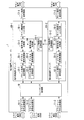
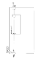
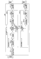
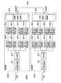
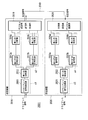
- FIGS. 1 and 2 are functional block diagrams showing the configuration of the transmission apparatus according to the first embodiment of the present invention.
- FIG. 1 shows a signal path on the transmission side
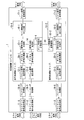
- FIG. 2 shows a signal path on the reception side.
- the transmission apparatus 1 shown in FIGS. 1 and 2 performs signal transmission between a (100GE ⁇ 3) client signal and a (150G ⁇ 2) line signal.
- a transmission device 1 is a component in which components for signal transmission are mounted on a single substrate, and is called a line card.
- the transmission apparatus 1 includes three client signal transmission / reception units 11-1, 11-2, and 11-3, a framing processing unit 19, signal processing units 10-1 and 10-2, and a line signal transmission / reception unit 17-1. , 17-2.
- the signal processing units 10-1 and 10-2 are formed into chips and are arranged on a line card constituting the transmission apparatus 1.
- the inter-chip wiring 18 is provided between the signal processing unit 10-1 and the signal processing unit 10-2.
- the signal processing unit 10-1 includes parallel signal transmitting / receiving units 12-1 and 12-2, digital signal processing units 20-1 and 20-2, a signal merging / branching unit 13-1, and a signal branching / merging unit 14. And an inter-chip signal transmission / reception unit 15-1 and a line side signal output / input unit 16-1.
- the signal processing unit 10-2 includes a parallel signal transmitting / receiving unit 12-3, a digital signal processing unit 20-3, a signal merging / branching unit 13-2, an interchip signal transmitting / receiving unit 15-2, and a line side signal output unit. And an input unit 16-2.
- An inter-chip wiring 18 is provided between the inter-chip signal transmitting / receiving unit 15-1 of the signal processing unit 10-1 and the inter-chip signal transmitting / receiving unit 15-2 of the signal processing unit 10-2.
- client signal transmission / reception units 11-1, 11-2, and 11-3 each receive a 100GE client signal and transfer the (100GE ⁇ 3) client signal to the framing processing unit 19.
- the framing processing unit 19 converts the client signal into a transport frame signal.
- the converted (100G ⁇ 3) transport frame is input to the parallel signal transmission / reception units 12-1 and 12-2 of the signal processing unit 10-1 and the parallel signal transmission / reception unit 12-3 of the signal processing unit 10-2. Is done.
- the framing processing unit 19 can be omitted.
- the parallel signal transmitting / receiving unit 12-1 transmits the received 100G transport frame signal to the digital signal processing unit 20-1.
- the digital signal processing unit 20-1 performs digital signal processing on the signal from the parallel signal transmission / reception unit 12-1 for transmission degradation equalization processing or the like.
- the signal output from the digital signal processing unit 20-1 is input to the signal merging / branching unit 13-1.
- the parallel signal transmitting / receiving unit 12-2 sends the received 100G transport frame signal to the digital signal processing unit 20-2.
- the digital signal processing unit 20-2 performs digital signal processing on the signal from the parallel signal transmission / reception unit 12-2 for transmission deterioration equalization processing or the like.
- the signal output from the digital signal processing unit 20-2 is input to the signal branching / merging unit 14.
- the signal branching / merging unit 14 branches the signal of the 100G transport frame digitally processed by the digital signal processing unit 20-2 at (1: 1).
- the signal branching / merging unit 14 branches the signal of the 100G transport frame into two 50G signals. Then, the signal branching / merging unit 14 transfers the branched 50G signal to the signal combining / branching unit 13-1, and transfers the other 50G signal to the inter-chip signal transmitting / receiving unit 15-1.
- the signal merging / branching unit 13-1 merges the 100G signal transferred from the digital signal processing unit 20-1 and the 50G signal transferred from the signal branching / merging unit 14 into a 150G signal.
- the signal is transferred to the line side signal input / output unit 16-1.
- the line side signal input / output unit 16-1 sends the received 150G signal to the line signal transmitting / receiving unit 17-1.
- the line signal transmission / reception unit 17-1 performs electro-optical conversion of the 150G signal and outputs the converted optical signal to the line side.
- the 50 G signal transferred from the signal branching / merging unit 14 to the inter-chip signal transmitting / receiving unit 15-1 is transferred to the inter-chip signal transmitting / receiving unit 15-2 via the inter-chip wiring 18.
- the inter-chip signal transmission / reception unit 15-2 receives the transmitted 50G signal, and transfers the received 50G signal to the signal merge / branch unit 13-2.
- the parallel signal transmitting / receiving unit 12-3 sends the received 100G transport frame signal to the digital signal processing unit 20-3.
- the digital signal processing unit 20-3 performs digital signal processing on the signal received from the parallel signal transmission / reception unit 12-3 for transmission degradation equalization processing or the like.
- the signal output from the digital signal processing unit 20-3 is input to the signal merge / branch unit 13-2.
- the signal combining / branching unit 13-2 combines the 50G signal received from the inter-chip signal transmitting / receiving unit 15-2 and the 100G signal received from the digital signal processing unit 20-3 into a 150G signal. Is transferred to the line side signal input / output unit 16-2.
- the line side signal input / output unit 16-2 sends the received 150G signal to the line signal transmitting / receiving unit 17-2.
- the line signal transmission / reception unit 17-2 performs electro-optical conversion of the 150G signal and outputs the converted signal to the line side.
- the transmission apparatus 1 receives a (150G ⁇ 2) line signal and transfers the received line signal as a (100GE ⁇ 3) client signal
- the (150G ⁇ 2) signal received by the line signal transmission / reception units 17-1 and 17-2 is converted into the line side signal input / output unit 16-1 and the signal processing unit 10-2 of the signal processing unit 10-1.
- the line side signal input / output unit 16-2 To the line side signal input / output unit 16-2.
- the line side signal input / output unit 16-1 transfers the received 150G signal to the signal merging / branching unit 13-1.
- the signal junction / branching unit 13-1 branches the received 150G signal into a 100G signal and a 50G signal. Then, the signal junction / branching unit 13-1 transfers the branched 100G signal to the digital signal processing unit 20-1, and transfers the 50G signal to the signal branching / merging unit 14.
- the digital signal processing unit 20-1 performs signal equalization or the like on the signal from the signal merging / branching unit 13-1 by digital signal processing to restore the signal of the 100G transport frame.
- the restored signal of the 100G transport frame is transferred to the parallel signal transmitting / receiving unit 12-1.
- the parallel signal transmission / reception unit 12-1 transfers the received 100G transport frame signal to the framing processing unit 19.
- the signal for 150 G received by the line signal transmitting / receiving unit 17-2 is transferred to the line side signal input / output unit 16-2 of the signal processing unit 10-2.
- the line side signal input / output unit 16-2 transfers the received 150G signal to the signal combining / branching unit 13-2.
- the signal merge / branch unit 13-2 branches the received 150G signal into a 100G signal and a 50G signal.
- the signal joining / branching unit 13-2 transfers the branched 100G signal to the digital signal processing unit 20-3, and transfers the branched 50G signal to the inter-chip signal transmitting / receiving unit 15-2.
- the digital signal processing unit 20-3 performs signal equalization or the like on the signal from the signal merging / branching unit 13-2 by digital signal processing to restore the signal of the 100G transport frame.
- the restored 100G transport frame signal is transferred to the parallel signal transmitting / receiving unit 12-3.
- the parallel signal transmission / reception unit 12-3 transfers the received 100G transport frame signal to the framing processing unit 19.
- the 50G signal transferred from the signal merge / branch unit 13-2 to the inter-chip signal transmission / reception unit 15-2 is transmitted via the inter-chip wiring 18 to the inter-chip signal transmission / reception unit.
- 15-1 is transferred.
- the inter-chip signal transmission / reception unit 15-1 receives the 50 G signal transmitted from the signal junction / branching unit 13-2 via the inter-chip wiring 18 and transfers the signal to the signal branch / merging unit 14.
- the signal branching / merging unit 14 joins the 50G signal received from the signal joining / branching unit 13-1 and the 50G signal received from the inter-chip signal transmitting / receiving unit 15-1.
- the merged signals for 100 G are transferred to the digital signal processing unit 20-2.
- the digital signal processing unit 20-2 performs signal equalization or the like on the signal from the signal branching / merging unit 14 by digital signal processing to restore a 100G transport frame.
- the restored 100G transport frame signal is transferred to the parallel signal transmitting / receiving unit 12-2.
- the parallel signal transmitting / receiving unit 12-2 transfers the received 100G transport frame signal to the framing processing unit 19.
- the framing processing unit 19 calculates (100GE ⁇ 3) from the (100G ⁇ 2) signal received from the parallel signal transmission / reception units 12-1 and 12-2 and the 100G signal received from the parallel signal transmission / reception unit 12-3. Restore the client signal.
- the restored (100GE ⁇ 3) client signals are transferred to the client signal transmitting / receiving units 11-1, 11-2, and 11-3, respectively.
- the client signal transmission / reception units 11-1, 11-2, and 11-3 output 100GE signals to the outside of the transmission apparatus.
- the signal processing unit 10-1 is provided with the signal merging / branching unit 13-1 and the signal branching / merging unit 14, and the signal processing unit 10-2 includes Is provided with a signal merging / branching portion 13-2.
- An inter-chip wiring 18 is provided between the inter-chip signal transmitting / receiving unit 15-1 of the signal processing unit 10-1 and the inter-chip signal transmitting / receiving unit 15-2 of the signal processing unit 10-2.
- FIG. 3 is a functional block diagram used for explaining a modification of the transmission apparatus according to the first embodiment of the present invention.
- framing processing units 19-1 and 19-2 may be provided in a chip constituting the signal processing unit 10-1.
- the framing processing unit 19-3 may be provided in the chip constituting the signal processing unit 10-2.
- FIG. 4 is a functional block diagram used for explaining a modification of the transmission apparatus according to the first embodiment of the present invention. As shown in FIG. 4, three framing processing units 19-4, 19-5, and 19-6 may be provided for each of the (100GE ⁇ 3) signals.
- the signal processing unit 10-1 includes two digital signal processing units 20-1 and 20-2, and the signal processing unit 10-2 includes one digital signal processing unit 20-3. Is provided.
- the configuration related to the signal processing units 10-1 and 10-2 is not limited to the above configuration.
- FIG. 5 is a functional block diagram used for explaining a modification of the transmission apparatus according to the first embodiment of the present invention.
- the signal processing unit 10-1 may be provided with digital signal processing units 20-4 and 20-5.
- the digital signal processing units 20-6 and 20-7 may be provided in the signal processing unit 10-2. That is, the digital signal processing units 20-1 to 20-7 may be arranged in front of the signal junction / branching units 13-1, 13-2 or the signal branch / merging unit 14.
- the digital signal processing units 20-1 to 20-7 may be arranged in the subsequent stage of the signal junction / branching units 13-1, 13-2 or the signal branching / merging unit 14.
- the digital signal processing units 20-1 to 20-7 may be disposed in both the signal merging / branching units 13-1 and 13-2, or the signal branching / merging unit 14 in both the previous stage and the subsequent stage.
- the digital signal processing units 20-4 to 20-7 perform digital signal processing for transmission deterioration equalization processing and the like, as with the digital signal processing units 20-1 to 20-3.
- FIG. 6 is a functional block diagram used for explaining a modification of the transmission apparatus according to the first embodiment of the present invention.
- the framing processing unit 19 may be omitted and the digital signal processing units 20-1 to 20-3 may be omitted.
- the branching ratio of the signal branching / merging unit 14 may be arbitrarily set to (5: 5, 3: 7, 2: 8) or the like.
- FIG. 7 is a block diagram schematically illustrating the configuration of the conventional transmission apparatus described in the background art.
- FIG. 8 is a block diagram schematically illustrating the configuration of the transmission apparatus according to this embodiment.
- a 100G client signal (for example, 100GE or OTU4) is input to a signal processing unit (chip) via 100G I / O (Input / Output), and digital signal processing is performed by the signal processing unit.
- the broken signal is converted into a 100G signal by, for example, modulation using QPSK, and the converted signal is output as a line signal.
- the conventional transmission apparatus cannot perform digital signal processing on three 100GE client signals and transmit the processed signals through two super channels.
- a 100G ⁇ 3 client signal (for example, 100GE ⁇ 3 or OTU4 ⁇ 3) is input, and among these, 100G ⁇ 2 client signals are two 100G I /
- the first signal processing unit (chip) is input to the first signal processing unit (chip) through O (corresponding to the client signal transmission / reception unit), and the second signal processing unit (chip) is transmitted through one 100G I / O. Is input.
- processing such as digital signal processing described in the present embodiment is performed, and a signal obtained by the processing is, for example, 100 G ⁇ 2 lines by modulation using 8QAM.
- the signal is converted into a signal, and the converted signal is output as a line signal.
- the transmission apparatus by providing a branch / merging unit in the signal processing unit, for example, processing is performed on three 100GE client signals, and the processed signals are transmitted by two super channels ( 300Q transmission using 8QAM 2SC (subcarrier) is possible.
- the transmission apparatus can cope with adaptive modulation / demodulation of BPSK (Binary Phase Shift Keying), QPSK, 8QAM, and 16QAM, and can accommodate a 100G client signal in the case of BPSK and QPSK.
- BPSK Binary Phase Shift Keying
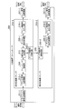
- FIGS. 9 and 14 are functional block diagrams showing the configuration of the transmission apparatus 201 according to the second embodiment of the present invention.
- FIG. 9 shows a signal path on the transmission side
- FIG. 14 shows a signal path on the reception side.
- the transmission apparatus 201 shown in FIGS. 9 and 14 transmits a signal by branching a 100GE client signal into a (50G ⁇ 2) line signal.
- the bit rate of the line signal is an example smaller than the bit rate of the client signal.
- the transmission apparatus 201 illustrated in FIGS. 9 and 14 includes a client signal transmission / reception unit 211-1, signal processing units 210-1 and 210-2, and line signal transmission / reception units 217-1 and 217-2.
- the signal processing units 210-1 and 210-2 are formed into chips and are arranged on a line card constituting the transmission apparatus 201.
- an inter-chip wiring 218 is provided between the signal processing unit 210-1 and the signal processing unit 210-2.
- the signal processing unit 210-1 includes a parallel signal transmission / reception unit 212-1, a framing processing unit 219, a signal branching / merging unit 213, a digital signal processing unit 220-1, and a line side signal input / output unit 216-1.
- the inter-chip signal transmission / reception unit 215-1 is provided.
- the signal processing unit 210-2 includes a digital signal processing unit 220-2, an inter-chip signal transmission / reception unit 215-2, and a line side signal input / output unit 216-2.
- An interchip wiring 218 is provided between the interchip signal transmission / reception unit 215-1 of the signal processing unit 210-1 and the interchip signal transmission / reception unit 215-2 of the signal processing unit 210-2.
- a client signal transmission / reception unit 211-1 of the transmission apparatus 201 receives a 100GE client signal and transfers the client signal to the parallel signal transmission / reception unit 212-1.
- the parallel signal transmission / reception unit 212-1 transfers the 100GE signal to the framing processing unit 219.
- the framing processing unit 219 converts the received client signal into a 100G transport frame signal.
- the converted 100G transport frame signal is transferred from the framing processing unit 219 to the signal branching / merging unit 213.
- the signal branching / merging unit 213 branches the signal of the 100G transport frame at (1: 1). Then, the signal branching / merging unit 213 transfers the branched 50G signal to the digital signal processing unit 220-1, and transfers the other 50G signal to the inter-chip signal transmitting / receiving unit 215-1.
- the signal branching / merging unit 213 branches the signal of the 100G transport frame at (1: 1)
- the signal branching / merging unit 213 includes the 100G transport frame configured by the framing processing unit 219.
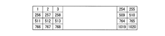
- the signal of (112G OTU4) is divided into blocks.
- the overhead is a divisor value of the size of the OTU4 frame
- the function unit that performs signal processing with reference to the distributed signal needs to detect the frame structure of the OTU4 frame Select a block size that divides a value greater than the number of bytes in the element.
- the frame size is 16320 bytes.
- the divisor of 16320 is 1, 2, 3, 4, 5, 6, 8, 10, 12, 15, 16, 17, 20, ..., 4080, 5440, 8160, 16320, and these values are blocks.
- the signal branching / merging unit 213 divides the OTU4 signal into blocks based on the value selected as the block size.
- FIG. 10A to 10E show examples in which a frame is divided into blocks.
- the digital signal processing unit 220-1 performs signal processing for transmission deterioration equalization processing on the input signal and transfers the signal-processed signal to the line side signal input / output unit 216-1.
- the line side signal input / output unit 216-1 transfers this signal to the line signal transmitting / receiving unit 217-1.
- the line signal transmission / reception unit 217-1 performs electro-optical conversion of the 50G signal and transmits the converted optical signal to the reception side.
- the 50 G signal input from the signal branching / merging unit 213 to the inter-chip signal transmission / reception unit 215-1 is transferred to the inter-chip signal transmission / reception unit 215-2 via the inter-chip wiring 218.
- the inter-chip signal transmission / reception unit 215-2 receives the 50G signal sent from the signal branching / merging unit 213 via the inter-chip signal transmission / reception unit 215-1 and the inter-chip wiring 218, and digitally converts the received signal to digital.
- the signal is sent to the signal processing unit 220-2.
- the digital signal processing unit 220-2 performs signal processing for transmission degradation equalization processing on the input signal and transfers the signal-processed signal to the line side signal input / output unit 216-2.
- the line side signal input / output unit 216-2 transfers this signal to the line signal transmitting / receiving unit 217-2.
- the line signal transmission / reception unit 217-2 performs electro-optical conversion on the 50G signal and transmits the converted optical signal to the reception side.
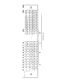
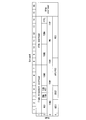
- FIG. 11 shows an example of processing when a 100G transport frame (112G) is branched into a 50G transport frame (56G).
- FIG. 12 shows a 100G transport frame input to the signal branching / merging unit 213.
- the 100G transport frame (112G) and the 50G transport frame (56G) are 4 columns (1 byte) ⁇ 4080 columns.
- OH overhead
- payload is set for 3808 bytes of 17 to 3824 columns
- FEC forward error correction: forward
- FS Fixed Stuff
- the 17th column to the 3816 column of the payload include 10 types of 10G TS (Tributary slot) is shown, and the number in the payload indicates the TS number.
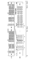
- the payload of the 100G transport frame shown in FIG. 11 includes 10 types of TSs TS1 to TS10.
- a half of the ten types of TS included in the payload of the 50G transport frame shown in FIG. 11 is a TS group A, and the other half is a TS group B.
- the 50G transport frame (1) includes five types of TSs TS1 to TS5 in each of the TS group A and the TS group B.
- the 50G transport frame (2) includes five types of TSs TS6 to TS10 in each of the TS group A and the TS group B.
- TS group A and TS group B are alternately arranged in the payload.
- the arrangement of TS group A and TS group B is not limited to this.
- TS group A is placed in the first half of the payload.
- the half area and TS group B may be the second half area of the payload.
- the signal branching / merging unit 213 extracts 50G TS at a predetermined position (TS1 to TS5) in the payload in the 100G transport frame of the first frame. Thereafter, the signal branching / merging unit 213 maps the extracted TS to a half TS (TS1 to TS5 of TS group A) at the determined position of the payload of the 50G transport frame (1). Further, the signal branching / merging unit 213 extracts 50G TS at a predetermined position (TS6 to TS10) in the payload in the 100G transport frame of the first frame.
- the signal branching / merging unit 213 maps the extracted TS to a half TS (TS6 to TS10 of TS group A) at the determined position of the payload of the 50G transport frame (2).
- the reason for using the half TS of the first frame is to change from the 100G transport frame (112G) to the 50G transport frame (56G).
- the signal branching / merging unit 213 extracts 50G TS set in the determined positions (TS1 to TS5) in the payload in the second 100G transport frame. Thereafter, the signal branching / merging unit 213 maps the extracted TS to a half TS (TS1 to TS5 of TS group B) at a predetermined position of the payload of the 50G transport frame (1). In addition, the signal branching / merging unit 213 extracts 50G TS set at a predetermined position (TS6 to TS10) in the payload in the second frame 100G transport frame. Thereafter, the signal branching / merging unit 213 maps the extracted TS to a half TS (TS6 to TS10 of TS group B) at the determined position of the payload of the 50G transport frame (2).
- the signal branching / merging unit 213 sets the OH of the 100G transport frame of the first frame to the OH of the 50G transport frame (1), and sets OH ′, which is the OH of the 100G transport frame of the second frame, to the 50G transport. Set to OH of port frame (2).
- the signal branching / merging unit 213 By mapping as described above, the signal branching / merging unit 213 generates 50G transport frames (1) and (2) from the 100G transport frame.
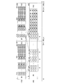
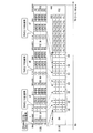
- FIG. 13 shows another example of processing when a 100G transport frame (112G) is branched into a 50G transport frame (56G).
- the difference between this example and the example shown in FIG. 11 is as follows.
- the signals of TS1 to TS5 (upward left slanting line) of the 100G transport frame of the first frame are copied to the TS (upward left slanting line) of column 1 and column 2 in the 50G transport frame (1).
- the signals of TS1 to TS5 (vertical line) of the 100G transport frame are copied to the TS (vertical line) of column 3 and column 4 of the 50G transport frame (1).
- TS6 to 10 (upward sloping lines) signals of the 100G transport frame of the first frame are copied to the TS (upward sloping lines) in column 1 and column 2 in the 50G transport frame (2).
- the signals of TS6 to TS10 (horizontal line) of the 100G transport frame of the second frame are copied to the TS (horizontal line) of column 3 and column 4 of the 50G transport frame (2).
- the transmission apparatus 201 receives a (50G ⁇ 2) line signal and transfers the received line signal as a 100GE client signal
- the (50G ⁇ 2) signal received by the line signal transmission / reception units 217-1 and 217-2 is sent to the line side signal input / output unit 216-1 and the signal processing unit 210-2 of the signal processing unit 210-1.
- the line side signal input / output unit 216-2 To the line side signal input / output unit 216-2.
- the line side signal input / output unit 216-1 transfers the received 50G signal to the digital signal processing unit 220-1.
- the digital signal processing unit 220-1 performs signal equalization or the like by digital signal processing on the signal from the line side signal input / output unit 216-1 to restore a 50G signal.
- the restored 50 G signal is transferred to the signal branching / merging unit 213.
- the line side signal input / output unit 216-2 transfers the received 50G signal to the digital signal processing unit 220-2.
- the digital signal processing unit 220-2 performs signal equalization or the like on the signal from the line side signal input / output unit 216-2 by digital signal processing, and restores a signal for 50G.
- the restored signal is transferred to the inter-chip signal transmission / reception unit 215-2.
- a 50G signal from the interchip signal transmission / reception unit 215-2 is transferred to the interchip signal transmission / reception unit 215-1 via the interchip wiring 218.
- the inter-chip signal transmission / reception unit 215-1 receives this 50G signal and sends the received signal to the signal branching / merging unit 213.
- the signal branching / merging unit 213 merges the 50G signal received from the digital signal processing unit 220-1 and the 50G signal received from the inter-chip signal transmission / reception unit 215-1 to generate a 100G transport frame. Restore the signal. Then, the signal branching / merging unit 213 transfers the 100G transport frame signal to the framing processing unit 219.
- the framing processing unit 219 restores the 100GE client signal from the 100G transport frame, and transfers the 100GE client signal to the parallel signal transmitting / receiving unit 212-1.
- the parallel signal transmitting / receiving unit 212-1 transfers this 100GE client signal to the client signal transmitting / receiving unit 211-1.
- the client signal transmitting / receiving unit 211-1 outputs the received 100GE client signal to the outside of the transmission apparatus.
- the signal branching / merging unit 213 performs a reverse conversion to the branching and restores the 100G transport frame from the two 50G transport frames. Processing in the signal branching / merging unit 213 at this time will be described.
- the signal branching / merging unit 213 converts TS1 to TS5 of the TS group A of the received 50G transport frame (1) into the 100G transport frame of the first frame. Map to port frames TS1 to TS5. Further, the signal branching / merging unit 213 maps TS6 to TS10 of the TS group A of the received 50G transport frame (2) to TS6 to TS10 of the first 100G transport frame. As described above, the first 100G transport frame is restored.
- the signal branching / merging unit 213 converts TS1 to TS5 of TS group B of the received 50G transport frame (1) into the 100G transport of the second frame. Map to frames TS1 to TS5. Further, the signal branching / merging unit 213 maps TS6 to TS10 of the TS group B of the received 50G transport frame (2) to TS6 to TS10 of the second 100G transport frame. As described above, the second 100G transport frame is restored. The signal branching / merging unit 213 transfers the restored 100G transport frame to the framing processing unit 219.
- the signal processing unit 210-1 is provided with the signal branching / merging unit 213.
- An interchip wiring 218 is provided between the interchip signal transmission / reception unit 215-1 of the signal processing unit 210-1 and the interchip signal transmission / reception unit 215-2 of the signal processing unit 210-2.
- a 100GE client signal can be branched and transferred to a (50G ⁇ 2) line signal.
- a (50G ⁇ 2) line signal can be transferred as a 100GE client signal.
- the framing processing unit 219 is provided in the chip constituting the signal processing unit 210-1, but the framing processing unit 219 is provided outside the chip constituting the signal processing unit 210-1.
- the framing processing unit 219 can be omitted.
- one digital signal processing unit 220-1 is provided in the signal processing unit 210-1, and one digital signal processing unit 220-2 is provided in the signal processing unit 210-2. Furthermore, you may make it provide a digital signal processing part in another position.
- the digital signal processing units 220-1 and 220-2 may be omitted.
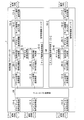
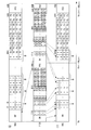
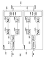
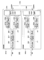
- FIG. 15 and 16 are functional block diagrams showing the configuration of the transmission apparatus 301 according to the third embodiment of the present invention.
- FIG. 15 shows a signal path on the transmission side
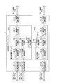
- FIG. 16 shows a signal path on the reception side.
- the transmission apparatus 301 shown in FIG. 15 transmits a (100GE ⁇ 4) client signal as a (133G ⁇ 3) line signal.
- the transmission apparatus 301 includes client signal transmission / reception units 311-1 to 311-4, framing processing units 319-1 to 319-4, signal processing units 310-1 to 310-3, and line signal transmission / reception units 317-1 to 317-1. 317-3.
- the signal processing units 310-1 to 310-3 are formed into chips and are arranged on a line card that constitutes the transmission apparatus 301.
- an inter-chip wiring 318-1 is provided between the signal processing unit 310-1 and the signal processing unit 310-2.
- An inter-chip wiring 318-2 is provided between the signal processing unit 310-1 and the signal processing unit 310-3.
- the signal processing unit 310-1 includes parallel signal transmission / reception units 312-1 and 312-2, a signal merging / branching unit 313-1, a signal branching / merging unit 314, a digital signal processing unit 320-1, and a line side.
- a signal input / output unit 316-1 and an interchip signal transmitting / receiving unit 315-1 are provided.
- the signal processing unit (chip) 310-2 includes a parallel signal transmitting / receiving unit 312-3, a signal merging / branching unit 313-2, a digital signal processing unit 320-2, a line side signal input / output unit 316-2, An inter-chip signal transmission / reception unit 315-2 is provided.
- the signal processing unit (chip) 310-3 includes a parallel signal transmitting / receiving unit 312-4, a signal merging / branching unit 313-3, a digital signal processing unit 320-3, a line side signal input / output unit 316-3, An inter-chip signal transmission / reception unit 315-3 is provided.
- An inter-chip wiring 318-1 is provided between the inter-chip signal transmission / reception unit 315-1 of the signal processing unit 310-1 and the inter-chip signal transmission / reception unit 315-2 of the signal processing unit 310-2.
- An inter-chip wiring 318-2 is provided between the inter-chip signal transmission / reception unit 315-1 of the signal processing unit 310-1 and the inter-chip signal transmission / reception unit 315-3 of the signal processing unit 310-3.
- the client signal transmission / reception units 311-1, 311-2, 311-3, 311-4 of the transmission apparatus 301 receive the 100GE client signal, and the received client signal is transmitted to the framing processing units 319-1, 319-. 2, 319-3, 319-4.
- the framing processing units 319-1, 319-2, 319-3, and 319-4 each convert a 100GE client signal into a 100G transport frame signal.
- Signals from the framing processing units 319-1 and 319-2 are input to the parallel signal transmission / reception units 312-1 and 312-2 of the signal processing unit 310-1.
- the signal from the framing processing unit 319-3 is input to the parallel signal transmission / reception unit 312-3 of the signal processing unit 310-2.
- the signal from the framing processing unit 319-4 is input to the parallel signal transmission / reception unit 312-4 of the signal processing unit 310-3.
- the signal received by the parallel signal transmitting / receiving unit 312-1 is transferred to the signal combining / branching unit 313-1.
- the signal received by the parallel signal transmitting / receiving unit 312-2 is transferred to the signal branching / merging unit 314.
- the signal branching / merging unit 314 branches the signal of the 100G transport frame received from the parallel signal transmitting / receiving unit 312-2 to (1: 1: 1). Then, the signal branch / merging unit 314 transfers one branched 33G signal to the signal merge / branch unit 313-1, and the remaining two 33G signals branched to the inter-chip signal transmitting / receiving unit 315-1. Forward.
- the branching ratio may be an arbitrary value according to the bit rate of the line signal.
- the signal combining / branching unit 313-1 combines the signal of the 100G transport frame received from the parallel signal transmitting / receiving unit 312-1 and the 33G signal received from the signal branching / merging unit 314, and combines the signals.
- the signal is transferred to the digital signal processing unit 320-1.
- the digital signal processing unit 320-1 performs signal processing on the received 133G signal for transmission degradation equalization processing, and transfers the signal-processed signal to the line side signal input / output unit 316-1. To do.
- the line side signal input / output unit 316-1 sends the received 133G signal to the line signal transmission / reception unit 317-1.
- the line signal transmitting / receiving unit 317-1 performs electro-optical conversion on the 133G signal and outputs the converted optical signal to the line side.
- the signal received by the parallel signal transmitting / receiving unit 312-3 is transferred to the signal combining / branching unit 313-2.
- One of the two 33G signals sent from the signal branching / merging unit 314 to the inter-chip signal transmission / reception unit 315-1 passes from the inter-chip signal transmission / reception unit 315-1 via the inter-chip wiring 318-1. It is transferred to the inter-chip signal transmission / reception unit 315-2.
- the inter-chip signal transmission / reception unit 315-2 transfers the received 33G signal to the signal merge / branch unit 313-2.
- the signal combining / branching unit 313-2 combines the signal of the 100G transport frame received from the parallel signal transmission / reception unit 312-3 and the 33G signal received from the inter-chip signal transmission / reception unit 315-2 to be combined.
- the 133G signal is transferred to the digital signal processing unit 320-2.
- the digital signal processing unit 320-2 performs signal processing on the received 133G signal for transmission degradation equalization processing, and transfers the signal-processed signal to the line side signal input / output unit 316-2. To do.
- the line-side signal input / output unit 316-2 sends the received 133G signal to the line signal transmitting / receiving unit 317-2.
- the line signal transmission / reception unit 317-2 performs electro-optical conversion on the received 133G signal and outputs the converted optical signal to the line side.
- the 100G signal received by the parallel signal transmitting / receiving unit 312-4 is transferred to the signal combining / branching unit 313-3.
- the remaining one of the two 33G signals sent from the signal branching / merging unit 314 to the inter-chip signal transmission / reception unit 315-1 is transmitted from the inter-chip signal transmission / reception unit 315-1 to the inter-chip wiring 318-1. Via, and transferred to the inter-chip signal transmission / reception unit 315-3.
- the inter-chip signal transmitting / receiving unit 315-3 transfers the received 33G signal to the signal combining / branching unit 313-3.
- the signal combining / branching unit 313-3 combines the signal of the 100G transport frame received from the parallel signal transmitting / receiving unit 312-4 and the 33G signal received from the inter-chip signal transmitting / receiving unit 315-3, and combines the signals.
- the 133G signal thus transferred is transferred to the digital signal processing unit 320-3.
- the digital signal processing unit 320-3 performs signal processing on the received 133G signal for transmission degradation equalization processing and the like, and transfers the signal-processed signal to the line side signal input / output unit 316-3 To do.
- the line side signal input / output unit 316-3 sends the received 133G signal to the line signal transmission / reception unit 317-3.
- the line signal transmission / reception unit 317-3 performs electro-optical conversion on the received 133G signal and outputs the converted optical signal to the line side.
- (133G ⁇ 3) signals received by the line signal transmission / reception units 317-1 to 317-3 are a line side signal output / input unit 316-1, a line side signal output / input unit 316-2, and a line side signal. Transferred to the input / output unit 316-3.
- the line side signal input / output unit 316-1 transfers the received 133G signal to the digital signal processing unit 320-1.
- the digital signal processing unit 320-1 performs signal equalization on the signal from the line side signal input / output unit 316-1 by digital signal processing.
- the 133G signal after signal equalization or the like is transferred to the signal merge / branch unit 313-1.
- the signal merging / branching unit 313-1 branches the received 133G signal into a 100G transport frame signal and a 33G signal. Then, the signal junction / branching unit 313-1 transfers the signal of the 100G transport frame to the parallel signal transmission / reception unit 312-1 and transfers the signal for 33G to the signal branching / merging unit 314.
- the line side signal input / output unit 316-2 transfers the 133G signal received from the line signal transmission / reception unit 317-2 to the digital signal processing unit 320-2.
- the digital signal processing unit 320-2 performs signal equalization on the signal from the line side signal input / output unit 316-2 by digital signal processing.
- the 133G signal after signal equalization or the like is transferred to the signal merge / branch unit 313-2.
- the signal merging / branching unit 313-2 branches the received 133G signal into a 100G transport frame signal and a 33G signal. Then, the signal junction / branching unit 313-2 transfers the branched 100G transport frame signal to the parallel signal transmission / reception unit 312-3, and also transmits the 33G signals to the inter-chip signal transmission / reception unit 315-2. Forward.
- the inter-chip signal transmission / reception unit 315-2 transfers the received 33G signal to the inter-chip signal transmission / reception unit 315-1 via the inter-chip wiring 318-1.
- the inter-chip signal transmitting / receiving unit 315-1 transfers the received 33G signal to the signal branching / merging unit 314.
- the line side signal input / output unit 316-3 transfers the 133G signal received from the line signal transmission / reception unit 317-3 to the digital signal processing unit 320-3.
- the digital signal processing unit 320-3 performs signal equalization by digital signal processing.
- the 133G signal after the signal equalization from the digital signal processing unit 320-3 is transferred to the signal merge / branch unit 313-3.
- the signal merge / branch unit 313-3 branches the received 133G signal into a 100G transport frame signal and a 33G signal.
- the signal combining / branching unit 313-3 transfers the 100G transport frame signal to the parallel signal transmitting / receiving unit 312-4, and transfers the 33G signal to the inter-chip signal transmitting / receiving unit 315-3. .
- the inter-chip signal transmission / reception unit 315-3 transfers the received 33G signal to the inter-chip signal transmission / reception unit 315-1 via the inter-chip wiring 318-2.
- the inter-chip signal transmitting / receiving unit 315-1 transfers the received 33G signal to the signal branching / merging unit 314.
- the signal branching / merging unit 314 joins the 33G signal received from the signal joining / branching unit 313-1 and the two 33G signals received from the inter-chip signal transmitting / receiving unit 315-1. Then, the signal branching / merging unit 314 restores the signal of the 100G transport frame, and transfers the restored signal to the parallel signal transmitting / receiving unit 312-2.
- the parallel signal transmission / reception units 312-1, 312-2, 312-3, 312-4 respectively receive the received 100G transport frame signals as framing processing units 319-1, 319-2, 319-3, 319. -4.
- the framing processing units 319-1, 319-2, 319-3, and 319-4 each restore a 100 GE client signal from a 100 G transport frame signal.
- the framing processing units 319-1, 319-2, 319-3, 319-4 transfer the client signal to the client signal transmitting / receiving units 311-1, 311-2, 311-3, 311-4.
- the client signal transmitting / receiving units 311-1, 311-2, 311-3, 311-4 output the received 100GE client signal to the outside of the transmission apparatus.
- the signal processing unit 310-1 is provided with the signal merging / branching unit 313-1 and the signal branching / merging unit 314.
- the signal processing unit 310-2 is provided with a signal merge / branch unit 313-2.
- the signal processing unit 310-3 is provided with a signal merge / branch unit 313-3.
- An inter-chip wiring 318-1 is provided between the inter-chip signal transmission / reception unit 315-1 of the signal processing unit 310-1 and the inter-chip signal transmission / reception unit 315-2 of the signal processing unit 310-2.
- an inter-chip wiring 318-2 is provided between the inter-chip signal transmitting / receiving unit 315-1 of the signal processing unit 310-1 and the inter-chip signal transmitting / receiving unit 315-3 of the signal processing unit 310-3.
- the client signal of (100GE ⁇ 4) can be transferred as the line signal of (133G ⁇ 3).
- a (133G ⁇ 3) line signal can be transferred as a (100GE ⁇ 4) client signal.
- the framing processing units 319-1 to 319-4 are provided outside the chips constituting the signal processing units 310-1 to 310-3, but the signal processing units 310-1 to 310-3 are provided.
- the framing processing units 319-1 to 319-4 may be provided in the chip constituting the circuit. If the client signal is already in the transport frame format, the framing processing units 319-1 to 319-4 can be omitted.
- each of the signal processing units 310-1 to 310-3 is provided with one digital signal processing unit 320-1 to 320-3, but the digital signal is also provided at another position.
- a processing unit may be provided.
- the digital signal processing units 320-1 to 320-3 may be omitted.
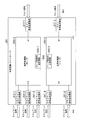
- ⁇ Extended example> 17 and 18 are functional block diagrams showing a configuration in which the transmission apparatus according to the first to third embodiments of the present invention is extended to a general example.
- the configuration shown in FIG. 17 is an example in which the number of ports corresponding to the number of channels on the line signal side for each of the signal processing units 510-1 and 510-2 is one.
- This extended example is an example in which a signal for one channel is output from the signal processing unit (chip).
- the signal processing units 510-1 and 510-2 are formed into chips and are arranged on a line card constituting the transmission apparatus 501.
- the signal processing units 510-1 and 510-2 include an inter-chip signal transmission / reception unit 515-1 and 515-2, a parallel signal transmission / reception unit, a framing processing unit, a digital signal processing unit, a signal merging / branching unit, A junction part, a line side signal input / output part (not shown), etc. are provided. Further, an inter-chip wiring 518 is provided between the inter-chip signal transmission / reception unit 515-1 of the signal processing unit 510-1 and the inter-chip signal transmission / reception unit 515-2 of the signal processing unit 510-2. A signal branched between the inter-chip signal transmission / reception unit 515-1 of the signal processing unit 510-2 and the inter-chip signal transmission / reception unit 515-2 of the signal processing unit 510-2 via the inter-chip wiring 518. Are sent and received.
- the signal is branched at a ratio of 1: 1 in the signal branching / merging unit in the signal processing units 510-1 and 510-2.
- the framing processing unit of the signal processing units 510-1 and 510-2 uses the client signal as a transport frame, the bit rate increases by the overhead of the transport frame with respect to the 250G signal.
- FIG. 18 is a functional block diagram showing another example of extension of the transmission apparatus according to the first to third embodiments of the present invention.
- This extended example is an example in which signals for a plurality of channels are output from a signal processing unit (chip).
- the line signal side port for each of the signal processing units 510-1 and 510-2 is one.
- the configuration shown in FIG. 18 has a plurality (two in this example) of ports on the line signal side for the signal processors 610-1 and 610-2.
- the signal processing units 610-1 and 610-2 are made into chips and arranged on a line card that constitutes the transmission apparatus 601.
- the signal processing units 610-1 and 610-2 include an inter-chip signal transmitting / receiving unit 615-1 and 615-2, a parallel signal transmitting / receiving unit, a framing processing unit, a digital signal processing unit, a signal merging / branching unit, a signal branching / branching unit, A junction part, a line side signal input / output part (not shown), etc. are provided. Further, an inter-chip wiring 618 is provided between the inter-chip signal transmitting / receiving unit 615-1 of the signal processing unit 610-1 and the inter-chip signal transmitting / receiving unit 615-2 of the signal processing unit 610-2.
- the signal branched between the inter-chip signal transmitting / receiving unit 615-1 of the signal processing unit 610-1 and the inter-chip signal transmitting / receiving unit 615-2 of the signal processing unit 610-2 via the inter-chip wiring 618. Are sent and received.
- the signal is branched at a ratio of 1: 1 in the signal branching / merging unit in the signal processing units 610-1 and 610-2.
- the client signal is a transport frame in the framing processing units of the signal processing units (chips) 610-1 and 610-2, the bit rate is increased by the overhead of the transport frame with respect to the 125G signal.
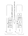
- FIG. 19 shows an outline of a multicarrier optical transmission system to which the signal branching / merging unit according to the first to third embodiments of the present invention can be applied.
- the multicarrier optical transmission system 701 includes a transmission device 710, a reception device 720, and an optical transmission path 740 that connects the transmission device 710 and the reception device 720.
- the client signal reception unit 711 receives a client signal such as 100GE or OTU4 from an external device connected to the transmission device 710.
- a client signal such as 100GE or OTU4 from an external device connected to the transmission device 710.
- the client signal receiving unit 711 outputs the received client signal as it is.
- the received client signal is 100GE
- the received client signal is mapped to the OTU4 frame, The OTU4 frame after mapping is output.
- the first distributor 712 divides the OTU4 frame signal output from the client signal receiver 711 into blocks.
- the first distribution unit 712 is a divisor value of the size of the OTU4 frame, and a function unit that performs signal processing with reference to the distributed signal has a function of the OTU4 frame.
- a value equal to or greater than the number of bytes of overhead elements required for detecting the frame structure is selected as the size of the block to be divided.
- the frame size is 16320 bytes.
- the divisor of 16320 is 1, 2, 3, 4, 5, 6, 8, 10, 12, 15, 16, 17, 20, ..., 4080, 5440, 8160, 16320, and these values are blocks.
- the error correction encoding units 713a and 713b add an error correction code to each signal distributed by the first distribution unit 712.
- the second distributors 716a and 716b distribute the signal to which the error correction code has been added by the error correction encoders 713a and 713b into two so as to correspond to the X polarization and the Y polarization.
- the second distribution units 716a and 716b perform signal processing with reference to the frame size of the signals output from the error correction coding units 713a and 713b and the signals after distribution. The signal distribution is performed based on the number of bytes of overhead elements necessary to detect the frame structure required by the processing of the functional unit to be performed.
- a training sequence for estimating chromatic dispersion or the like may be added.
- the digital modulation unit uses the 2SC-DP-BPSK system for each of the X polarization and Y polarization signals distributed by the second distribution units 716a and 716b.
- the transmission unit transmits the modulated signal, and the multiplexing unit wavelength-multiplexes the modulated signal to generate a transmission signal, and outputs the transmission signal.
- the output transmission signal is transmitted over a long distance through the optical transmission line 740.
- the demultiplexing unit divides the optical signal (transmission signal) for each subcarrier, and then converts the signal divided for each subcarrier to X polarization.
- the signal is demultiplexed into the Y-polarized wave
- the receiving unit reads out the demultiplexed signal
- the digital demodulating unit demodulates the read out signal, so that the demultiplexed X-polarized wave and Y-polarized wave are obtained.
- the second coupling units 726a and 726b detect FAS (Frame Alignment Signal) bytes from two signal blocks of X polarization and Y polarization, respectively.
- the second combining units 726a and 726b reorder and deskew the two signal blocks using the detected FAS byte to reproduce the original signal, and output the reproduced signal.
- the error correction decoding units 723a and 723b perform error correction processing on the signals output from the second combining units 726a and 726b, respectively.
- the first combining unit 722 detects the FAS byte from the two signal blocks output from the error correction decoding units 723a and 723b.
- the first combining unit 722 reorders and deskews the two signal blocks using the detected FAS byte, reproduces the original OTU4 frame structure signal, and outputs the reproduced signal.
- the client signal transmission unit 721 outputs the signal of the OTU4 frame output from the first combining unit 722 as it is, or converts the signal of the OTU4 frame into a 100GE signal and outputs the converted signal.
- the signal branching / merging unit uses the first distribution unit 712 to divide the OTU4 frame signal into blocks,
- the first combining unit 722 can be used when the divided block is combined with an OTU4 frame signal.
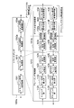
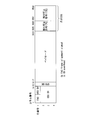
- FIG. 20 is a functional block diagram showing the configuration of the transponder of the optical communication system that enables transfer even when the bit rate of the line signal is variable.
- the transponder 801 includes a client signal transmission / reception unit 811, a framing processing unit 812, a digital signal processing unit 813, and a line signal transmission / reception unit 814.
- the framing processing unit 812 includes an OTU4 framer (OTU4 Framer)
- the digital signal processing unit 813 includes a digital coherent signal processing LSI (Large Scale Integration) (DSP-LSI (Digital Signal Processing LSI)).
- LSI Large Scale Integration
- DSP-LSI Digital Signal Processing LSI
- the client signal transmission / reception unit 811 transmits / receives a client signal.
- the line signal transmission / reception unit 814 transmits / receives a line signal to / from the opposite transponder 801 via a network.
- the framing processing unit 812 maps the client signal to the transport frame.
- the framing processing unit 812 includes a mapping unit 921, a dummy signal insertion unit 922, an overhead addition unit 923, a parallel signal transmission unit 924, a parallel signal reception unit 925, an overhead extraction unit 926, a dummy signal extraction unit 927, and a demapping unit 928. It is prepared for.
- the digital signal processing unit 813 performs signal equalization processing or the like for deterioration in the optical transmission path.
- the digital signal processing unit 813 includes a parallel signal reception unit 931, a transmission-side rate conversion unit 932, an error correction coding unit 933, a digital signal transmission processing unit 934, a digital signal reception processing unit 935, an error correction decoding unit 936, and a reception side.
- a rate conversion unit 937 and a parallel signal transmission unit 938 are provided.
- the client signal transmission / reception unit 811 of the transponder 801 transmits the client signal to the framing processing unit 812.
- the mapping unit 921 of the framing processing unit 812 maps the client signal to a 100G transport frame that is a transport frame equivalent to OTU4 because the interface (OTL4.10) between the OTU4 framer and the DSP is 112G compatible with OTU4.
- the dummy signal insertion unit 922 inserts a dummy signal such as FS into the signal output from the mapping unit 921.
- the overhead adding unit 923 adds the OTN OH to the data output from the dummy signal inserting unit 922, and sends the data with the added OH to the parallel signal transmitting unit 924 as a transport frame corresponding to OTU4.
- the parallel signal transmission unit 924 sends the transport frame output from the overhead adding unit 923 in parallel to the digital signal processing unit 813 of the DSP through an OTL (Optical channel channel) 4.10 interface.
- the parallel signal receiving unit 931 of the DSP restores the transport frame of OTU4 received from the framer (framing processing unit 812), and sends the restored transport frame to the transmission-side rate conversion unit 932.
- the transmission-side rate conversion unit 932 extracts a dummy signal such as FS inserted by the OTU4 framer (framing processing unit 812) from the transport frame of the OTU4 restored by the parallel signal reception unit 931, and generates a 50G transport frame (56G). Is generated.
- the transmission-side rate conversion unit 932 outputs the generated 50G transport frame to the error correction encoding unit 933.
- the error correction encoding unit 933 adds the error correction code to the 50G transport frame, and transmits the 50G transport frame with the error correction code added to the digital signal transmission processing unit 934.
- the digital signal transmission processing unit 934 performs optical digital coherent processing for long-distance transmission on the 50G transport frame, and transmits the processed 50G transport frame to the line signal transmission / reception unit 814.
- the line signal transmission / reception unit 814 performs E / O conversion on the 50G transport frame data output from the digital signal processing unit 813, and transmits the converted optical signal data to the network as a line signal.
- the transmitted data is received by the line signal transmission / reception unit 814 of the opposite transponder 801.
- the line signal transmission / reception unit 814 of the opposite transponder 801 performs O / E (Optic / Electric) conversion on the received data, and then outputs an electrical signal obtained by the conversion to a DSP (digital signal processing unit 813).
- the digital signal reception processing unit 935 of the digital signal processing unit 813 performs signal equalization on the received data and outputs a 50G transport frame.
- the error correction decoding unit 936 performs error correction processing on the 50G transport frame output from the digital signal reception processing unit 935.
- the error correction decoding unit 936 transmits the 50G transport frame subjected to the error correction process to the reception-side rate conversion unit 937.
- the reception-side rate conversion unit 937 performs reverse conversion to the transmission-side rate conversion unit 932, and generates a 100G transport frame (OTU4: 112G) from the 50G transport frame (56G) output from the error correction decoding unit 936. .
- the reception-side rate conversion unit 937 sends the restored 100G transport frames (OTU4: 112G) for two frames to the parallel signal transmission unit 938.
- the parallel signal transmission unit 938 transmits a 100G transport frame (OTU4: 112G) in parallel to the OTU4 framer (framing processing unit 812) through the OTL4.10 interface between the DSP and the OTU4 framer.
- the parallel signal receiving unit 925 of the OTU4 framer restores the 100G transport frame (OTU4: 112G) and sends the restored 100G transport frame to the overhead extracting unit 926.
- the overhead extraction unit 926 performs processing related to overhead such as error monitoring on the restored 100G transport frame (OTU4: 112G), and then sends the processed 100G transport frame to the dummy signal extraction unit 927.
- the dummy signal extraction unit 927 extracts dummy signals from 50G TS (for example, TS6 to TS10) included in a predetermined position in the payload of the 100G transport frame (OTU4: 112G).
- the dummy signal extraction unit 927 sends the 100G transport frame (OTU4: 112G) from which the dummy signal has been extracted to the demapping unit 928.
- the demapping unit 928 extracts the client signal from the 100G transport frame (OTU4: 112G).
- the demapping unit 928 sends the extracted 10GE ⁇ 5 client signal to the client signal transmitting / receiving unit 811.
- the client signal transmission / reception unit 811 outputs the client signal received from the framer (framing processing unit 812).
- the signal branching / merging unit generates a 50G transport frame from a transport frame of 100G OTU4 at the transmission-side rate conversion unit 932. This can be used when the receiving side rate conversion unit 937 generates a 100G transport frame from a 50G transport frame.
- FIG. 21 is a diagram showing an outline of the fourth to eleventh embodiments.
- the communication system of these embodiments is configured by connecting a transponder 1001 on a signal transmission side and a transponder 1001 on a reception side through a network.
- the transmission-side and reception-side transponders 1001 that are frame rate conversion apparatuses have the same configuration, and include a framer having a framing processing unit 1012 and a DSP having a digital signal processing unit 1013.
- OTL 4.10 is used for the interface between the framer and the DSP.
- the figure shows an outline of processing of the transponder 1001 on the transmission side.
- the framing processing unit 1012 in the framer of the transponder 1001 on the transmission side, has a transformer equal to the bit rate (third transfer rate) of the interface between the framer and the DSP. Configure the port frame. By configuring such a transport frame, it is possible to transfer a signal from the framer to the DSP. When configuring the transport frame, the dummy signal insertion unit 1122 of the framing processing unit 1012 inserts a dummy signal into the TS of the payload of the transport frame between the framer and the DSP.
- the bit rate of the payload of the transport frame for example, about 104 G for OPU (Optical channel channel Payload Unit) 4 and the bit rate Bc of the client signal (for example, 10GE ⁇ 5: about 52G, first Match the transfer rate).
- the dummy signal inserting unit 1122 inserts a dummy signal having a data amount that is insufficient for transfer at the transfer rate between the framer and the DSP. G represents gigabit.
- the transmission-side rate conversion unit 1132 of the digital signal processing unit 1013 extracts the dummy signal from the payload of the transport frame received from the framer, and the line signal bit rate Bl (second transfer rate) ) To create a transport frame according to This enables transfer even when the bit rate B1 of the line signal is variable.
- the digital signal processing unit 1013 inserts a dummy signal when setting the line signal received from the transmitting transponder 1001 as the payload of the transport frame between the framer and the DSP.
- a transport frame equal to the bit rate of the interface between the framer and the DSP is restored from the transport frame corresponding to the bit rate B1 of the line signal.
- the framing processing unit 1012 restores the client signal by removing the dummy signal from the transport frame in which the dummy signal received from the DSP is set, and outputs the restored client signal.
- FIG. 22 is a functional block diagram showing a configuration of a transponder 1001 according to the fourth embodiment of the present invention.
- the configuration of the transponder 1001 is basically the same as the configuration of the transponder 801 shown in FIG.
- the transponder 1001 includes a client signal transmission / reception unit 1011, a framing processing unit 1012, a digital signal processing unit 1013, and a line signal transmission / reception unit 1014.
- the framing processing unit 1012 is provided in the OTU4 framer
- the digital signal processing unit 1013 is provided in the digital coherent signal processing LSI (DSP).
- DSP digital coherent signal processing LSI
- the client signal transmission / reception unit 1011 transmits / receives a client signal.
- the line signal transmission / reception unit 1014 transmits / receives a line signal to / from the opposite transponder 1001 via a network.
- the framing processing unit 1012 maps the client signal to the transport frame.
- the framing processing unit 1012 includes a mapping unit 1121, a dummy signal insertion unit 1122, an overhead addition unit 1123, a parallel signal transmission unit 1124, a parallel signal reception unit 1125, an overhead extraction unit 1126, a dummy signal extraction unit 1127, and a demapping unit 1128. It is prepared for.
- the mapping unit 1121 maps the client signal sent from the client signal transmission / reception unit 1011 to a transport frame corresponding to the interface between the framer and the DSP, and transfers the transport frame obtained by the mapping to the dummy signal insertion unit 1122. Output.
- the dummy signal insertion unit 1122 inserts a dummy signal into the transport frame output from the mapping unit 1121 and outputs the transport frame with the dummy signal inserted to the overhead adding unit 1123.
- the overhead adding unit 1123 adds overhead information to the transport frame in which the dummy signal is inserted by the dummy signal inserting unit 1122, and outputs the transport frame to which the overhead information is added to the parallel signal transmitting unit 1124.
- the parallel signal transmission unit 1124 transfers the transport frame to which the overhead is added by the overhead addition unit 1123 to the digital signal processing unit 1013 from the framing processing unit 1012 in parallel through the interface between the framer and the DSP.
- the parallel signal receiving unit 1125 sets the signal transferred in parallel from the digital signal processing unit 1013 through the framer-DSP interface as a transport frame, and outputs the transport frame in which the signal is set to the overhead extracting unit 1126.
- the overhead extraction unit 1126 extracts the overhead of the transport frame output from the parallel signal reception unit 1125 and performs processing related to the overhead.
- the dummy signal extraction unit 1127 extracts the dummy signal from the transport frame output from the overhead extraction unit 1126 and outputs the transport frame from which the dummy signal is extracted to the demapping unit 1128.
- the demapping unit 1128 restores the client signal from the transport frame from which the dummy signal is removed by the dummy signal removal unit 1127, and outputs the restored client signal to the client signal transmission / reception unit 1011.
- the digital signal processing unit 1013 performs signal equalization processing on deterioration in the optical transmission path.
- the digital signal processing unit 1013 includes a parallel signal receiving unit 1131, a transmission-side rate conversion unit 1132, an error correction coding unit 1133, a digital signal transmission processing unit 1134, a digital signal reception processing unit 1135, an error correction decoding unit 1136, and a receiving side.
- a rate conversion unit 1137 and a parallel signal transmission unit 1138 are provided.
- the parallel signal receiving unit 1131 restores the transport frame from the signal sent in parallel from the framing processing unit 1012 through the framer-DSP interface, and outputs the restored transport frame to the transmission-side rate converting unit 1132.
- the transmission-side rate conversion unit 1132 extracts a dummy signal from the transport frame restored by the parallel signal reception unit 1131 to form a transport frame that matches the line-side rate, and error-corrects the configured transport frame.
- the data is output to the encoding unit 1133.
- the error correction encoding unit 1133 adds an error correction code to the transport frame output from the transmission side rate conversion unit 1132 and outputs the transport frame with the error correction code added to the digital signal transmission processing unit 1134.
- the digital signal transmission processing unit 1134 performs processing for signal equalization on the transport frame output from the error correction encoding unit 1133, and outputs the processed transport frame to the line signal transmission / reception unit 1014.
- the digital signal reception processing unit 1135 outputs a transport frame obtained as a result of performing signal equalization processing on the signal transferred from the line signal transmission / reception unit 1014 to the error correction decoding unit 1136.
- the error correction decoding unit 1136 outputs the transport frame obtained by performing error correction decoding on the transport frame output from the digital signal reception processing unit 1135 to the reception-side rate conversion unit 1137.
- the reception-side rate conversion unit 1137 converts the transport frame corresponding to the interface between the framer and the DSP so that the transport frame that has been subjected to error correction decoding by the error correction decoding unit 1136 can be transferred to the framing processing unit 1012.
- the transport frame thus configured is output to the parallel signal transmission unit 1138.
- the parallel signal transmission unit 1138 transfers the transport frame output from the reception-side rate conversion unit 1137 to the framing processing unit 1012 in parallel via the framer-DSP interface.
- the client signal transmission / reception unit 1011 of the transponder 1001 transmits the client signal to the framing processing unit 1012.
- the mapping unit 1121 of the framing processing unit 1012 maps a client signal to a 100G transport frame, which is a transport frame equivalent to OTU4, because the interface (OTL4.10) between the OTU4 framer and the DSP is 112G compatible with OTU4.
- FIG. 23A is a diagram showing a frame configuration of a 100G transport frame
- FIG. 23B is a diagram showing a frame configuration of a 50G transport frame.
- the 100G transport frame is a transport frame used for a 100G series interface
- the 50G transport frame is a transport frame used for a 50G series interface.
- 112G is transferred in a 100G transport frame, it is described as a 100G transport frame (112G).
- the 100G transport frame and the 50G transport frame are 4 columns (1 byte) ⁇ 4080 columns.
- OH overhead
- payload is set in 3808 bytes of 17 to 3824 columns
- FEC information is set in 256 bytes of 3825 to 4080 columns.
- FS is set in 3817 bytes to 3824 bytes in the payload.
- the 17th to 3816th columns of the payload include 10 types of 10G TS, and the numbers in the payload indicate the TS numbers.
- TS group A includes 10 types of TSs TS1 to TS10. Assume that half of the 10 types of TS included in the payload of the 50G transport frame shown in FIG. 23B is TS group A, and the other half is TS group B. Each of TS group A and TS group B includes five types of TSs TS1 to TS5. In the figure, TS group A and TS group B are alternately arranged in the payload, but the arrangement of TS group A and TS group is not limited to this. For example, TS group A is the first half of the payload. The TS group B may be the second half of the payload.
- the mapping unit 1121 of the OTU4 framer When mapping a client signal to a 100G transport frame equivalent to OTU4, the mapping unit 1121 of the OTU4 framer has a TS of 50G at a predetermined position in the payload (for example, the 17th column to the 17th column of the 100G transport frame in FIG. 23A).
- the client signal is mapped to TS1 to TS5) in the 3816 column.
- the dummy signal insertion unit 1122 sets dummy signals such as FS in the remaining 50G TS (for example, TS6 to TS10 in columns 17 to 3816 in FIG. 23A) in the 100G transport frame.
- the overhead adding unit 1123 adds OH to the data output from the dummy signal inserting unit 1122 through the transport frame corresponding to OTU4, and sends the data with the added OH to the parallel signal transmitting unit 1124.
- the parallel signal transmitting unit 1124 transmits the transport frame output from the overhead adding unit 1123 to the digital signal processing unit 1013 of the DSP in parallel via the OTL 4.10 interface.
- the parallel signal receiving unit 1131 of the DSP restores the transport frame of OTU4 received from the framer (framing processing unit 1012), and sends the restored transport frame to the transmission-side rate converting unit 1132.
- the transmission-side rate conversion unit 1132 removes the dummy signal such as FS inserted by the OTU4 framer (framing processing unit 1012) from the transport frame of the OTU4 restored by the parallel signal reception unit 1131, and the 50G transport frame ( 56G).
- FIG. 24 is a diagram showing an outline of transport frame conversion processing by the transmission-side rate conversion unit 1132.
- the first 100G transport frame corresponds to a signal from time T0 to time T0 + 1.168 ⁇ s (microseconds), and the second 100G transport frame from time T0 + 1.168 ⁇ s to time T0 + 2 ⁇ 1.168 ⁇ s. It corresponds to the signal up to.
- a 50G transport frame which is a transport frame used for a 50G series signal corresponds to a signal from time T0 to time T0 + 2 ⁇ 1.168 ⁇ s in one frame.
- the transmission-side rate conversion unit 1132 extracts a client signal from 50G TS (5/10 TS) at a predetermined position in the payload in each 100G transport frame (112G) of 2 frames of OTU4.
- the transmission-side rate conversion unit 1132 sets the extracted client signal at a determined position of the payload of the 50G transport frame (56G).
- FIG. 25 is a diagram illustrating processing in which the transmission-side rate conversion unit 1132 converts a 100G transport frame (OTU4: 112G) into a 50G transport frame, and shows details of FIG. A shaded TS in the 100G transport frame (OTU4: 112G) indicates that a dummy signal is set.
- the transmission-side rate conversion unit 1132 forms one 50G transport frame (56G) from 100G transport frames (112G) for two frames. Therefore, the transmission-side rate conversion unit 1132 extracts a client signal from 50G TS at a predetermined position (TS1 to TS5) in the payload in the 100G transport frame (112G) of the first frame OTU4.
- the transmission-side rate conversion unit 1132 maps the extracted client signal to a half TS (TS1 to TS5 of TS group A) at a determined position of the payload of the 50G transport frame (56G).
- the reason for using half the TS is to change from the 100G transport frame (112G) to the 50G transport frame (56G).
- the transmission-side rate conversion unit 1132 extracts the 50G TS set in the determined position (TS1 to TS5) in the payload in the 100G transport frame of the OTU4 of the second frame, and the client is extracted from the extracted TS. Extract the signal.
- the transmission-side rate conversion unit 1132 maps the extracted client signal to the remaining half TS (TS1 to TS5 of TS group B) of the payload of the 50G transport frame (56G).
- the transmission-side rate conversion unit 1132 sets the OH of the OTU4 of the first frame to the OH of the 50G transport frame (56G), and deletes OH ′ that is the OH of the OTU4 of the second frame. By mapping as described above, the transmission-side rate conversion unit 1132 generates a 50G transport frame (56G) from the 100G transport frame (OTU4: 112G).
- the transmission-side rate conversion unit 1132 outputs the generated 50G transport frame to the error correction encoding unit 1133.
- the error correction encoding unit 1133 adds the error correction code to the 50G transport frame, and transmits the transport frame to which the error correction code is added to the digital signal transmission processing unit 1134. Note that the error correction encoding unit 1133 may be omitted.
- the digital signal transmission processing unit 1134 performs optical digital coherent processing for long-distance transmission on the 50G transport frame, and transmits the processed 50G transport frame to the line signal transmission / reception unit 1014. Note that the digital signal transmission processing unit 1134 may be omitted.
- the line signal transmission / reception unit 1014 performs E / O conversion on the 50G transport frame data output from the digital signal processing unit 1013, and transmits the optical signal obtained by the conversion to the network as a line signal.
- the transmitted data is received by the line signal transmitting / receiving unit 1014 of the opposite transponder 1001.
- the line signal transmission / reception unit 1014 of the opposite transponder 1001 performs O / E conversion on the received data, and then outputs an electrical signal obtained by the conversion to a DSP (digital signal processing unit 1013).
- the digital signal reception processing unit 1135 of the digital signal processing unit 1013 performs signal equalization on the received data and outputs a 50G transport frame.
- the error correction decoding unit 1136 performs error correction processing on the 50G transport frame output from the digital signal reception processing unit 1135.
- the error correction decoding unit 1136 transmits the 50G transport frame subjected to the error correction processing to the reception-side rate conversion unit 1137.
- the reception-side rate conversion unit 1137 performs reverse conversion to the transmission-side rate conversion unit 1132 and generates a 100G transport frame (OTU4: 112G) from the 50G transport frame (56G) output from the error correction decoding unit 1136. . Specifically, the reception-side rate conversion unit 1137 determines half of the received 50G transport frame (56G) (TS1 to TS5 of TS group A) in the payload of the first frame of 100G transport frame. Mapping to 50G TS (for example, TS1 to TS5) included in the specified position. The reception-side rate conversion unit 1137 inserts a dummy signal such as FS into the remaining 50G TS (for example, TS6 to TS10) in the payload of the 100G transport frame.
- a dummy signal such as FS into the remaining 50G TS (for example, TS6 to TS10) in the payload of the 100G transport frame.
- the reception-side rate conversion unit 1137 determines the remaining half of the received 50G transport frame (56G) (TS1 to TS5 of TS group B) in the payload of the second 100G transport frame. To 50G TS (for example, TS1 to TS5) included in. The reception-side rate conversion unit 1137 inserts dummy signals such as FS into the remaining 50G TS (for example, TS6 to TS10) in the payload in the second 100G transport frame as well as the first frame. .
- the reception-side rate conversion unit 1137 copies the OH of the 50G transport frame (56G) as it is to the OH of the OTU4 in the first 100G transport frame.
- the reception-side rate conversion unit 1137 may copy the OH of the 50G transport frame as it is to the OH of the OTU4 in the second 100G transport frame, or may insert other data.
- two 100G transport frames (OTU4) are restored from one 50G transport frame.
- the reception-side rate conversion unit 1137 sends the restored 100G transport frames (OTU4: 112G) for two frames to the parallel signal transmission unit 1138.
- the parallel signal transmission unit 1138 transmits a 100G transport frame (OTU4: 112G) in parallel to the OTU4 framer (framing processing unit 1012) through the OTL4.10 interface between the DSP and the OTU4 framer.
- the parallel signal receiving unit 1125 of the OTU4 framer restores the 100G transport frame (OTU4: 112G), and sends the restored 100G transport frame to the overhead extracting unit 1126.
- the overhead extraction unit 1126 performs processing related to overhead such as error monitoring on the restored 100G transport frame (OTU4: 112G), and then sends the processed 100G transport frame to the dummy signal extraction unit 1127.
- the dummy signal extracting unit 1127 extracts dummy signals from 50G TS (for example, TS6 to TS10) included in a predetermined position in the payload of the 100G transport frame (OTU4: 112G).
- the dummy signal extraction unit 1127 sends the 100G transport frame (OTU4: 112G) from which the dummy signal has been extracted to the demapping unit 1128.
- the demapping unit 1128 extracts the client signal from the 100G transport frame (OTU4: 112G). Note that the demapping unit 1128 may restore the client signal directly from the 100G transport frame (OTU4: 112G) without extracting the dummy signal.
- the demapping unit 1128 sends the extracted 10GE ⁇ 5 client signal to the client signal transmitting / receiving unit 1011.
- the client signal transmission / reception unit 1011 outputs the client signal received from the framer (framing processing unit 1012).
- the present embodiment when a 50G transport frame to be transferred between the transponders 1001 is created in the transponder 1001 on the transmission side, one of the two OTU4 transport frames used for transfer between the framer and the DSP is used. Only the OH information is used, and the other OH is deleted. Therefore, this embodiment is suitable for the case where it is not necessary to transfer one OH.
- the difference between the fifth embodiment and the fourth embodiment is the OH transfer method of the OTU 4 in the second frame.
- a part of the OH of the OTU 4 in the second frame is transferred by FS (fixed pattern setting area) in the payload of the transport frame transferred between the transponders.
- FS fixed pattern setting area
- the transponder of this embodiment has the same configuration as the transponder 1001 of the fourth embodiment shown in FIG.
- the framing processing unit 1012 is provided in the OTU4 framer
- the digital signal processing unit 1013 is provided in the digital coherent signal processing LSI (DSP).
- DSP digital coherent signal processing LSI
- the transfer is performed when the bit rate of the client signal is 52 G, the OTL 4.10 corresponding to OTU4 of 112 G is applied to the interface between the OTU4 framer and the DSP, and the bit rate of the line signal is 56 G.
- An example is shown.
- the process from when the 10GE ⁇ 5 (about 52G) client signal is input to the transponder 1001 until the DSP parallel signal reception unit 1131 outputs the restored OTU4 frame to the transmission-side rate conversion unit 1132 This is the same as the embodiment. That is, the client signal transmission / reception unit 1011 of the transponder 1001 transmits the client signal to the framing processing unit 1012.
- the mapping unit 1121 of the framing processing unit 1012 maps the client signal to a 100G transport frame equivalent to OTU4 because the interface (OTL 4.10) between the OTU4 framer and the DSP is 112G compatible with OTU4.
- the mapping unit 1121 of the OTU4 framer When mapping a client signal to a 100G transport frame equivalent to OTU4, the mapping unit 1121 of the OTU4 framer has a TS of 50G at a predetermined position in the payload (for example, the 17th column to the 17th column of the 100G transport frame in FIG. 23A).
- the client signal is mapped to TS1 to TS5) in the 3816 column.
- the dummy signal insertion unit 1122 sets dummy signals such as FS in the remaining 50G TS in the 100G transport frame (for example, TS6 to TS10 in columns 17 to 3816 in FIG. 23A), and the dummy signal is set.
- the obtained 100G transport frame is output to the overhead adding unit 1123.
- the overhead adding unit 1123 adds OH to the data output from the dummy signal inserting unit 1122 through the transport frame corresponding to OTU4, and sends the data with the added OH to the parallel signal transmitting unit 1124.
- the parallel signal transmitting unit 1124 transmits the transport frame output from the overhead adding unit 1123 to the digital signal processing unit 1013 of the DSP in parallel via the OTL 4.10 interface.
- the parallel signal receiving unit 1131 of the DSP restores the OTU4 transport frame received from the OTU4 framer (framing processing unit 1012), and sends the restored transport frame to the transmission-side rate converting unit 1132.
- the transmission-side rate conversion unit 1132 removes the dummy signal such as FS inserted by the OTU4 framer (framing processing unit 1012) from the transport frame of the OTU4 restored by the parallel signal reception unit 1131, and the 50G transport frame ( 56G).
- FIG. 26 is a diagram illustrating a process in which the transmission-side rate conversion unit 1132 converts a 100G transport frame (OTU4: 112G) into a 50G transport frame.
- the transmission-side rate conversion unit 1132 determines the position (TS1 to TS5) in the payload in the 100G transport frame (112G) of the OTU4 of the first frame.
- a client signal is extracted from 50G TS.
- the transmission-side rate conversion unit 1132 maps the extracted client signal to a half TS (TS1 to TS5 of TS group A) at a determined position of the payload of the 50G transport frame (56G).
- the transmission-side rate conversion unit 1132 extracts the 50G TS set in the determined position (TS1 to TS5) in the payload in the 100G transport frame of the OTU4 of the second frame, and the client is extracted from the extracted TS. Extract the signal.
- the transmission-side rate conversion unit 1132 maps the extracted client signal to the remaining half TS (TS1 to TS5 of TS group B) of the payload of the 50G transport frame (56G).
- the transmission-side rate conversion unit 1132 sets the OH of the OTU4 of the first frame to the OH of the 50G transport frame (56G). Further, the transmission-side rate conversion unit 1132 inserts a part of OH ′ that is the OH of the OTU4 of the second frame into 4 rows (row) ⁇ 8 columns (column) of columns 3817 to 3824 of the 50G transport frame. To do.
- FIG. 27 is a diagram showing an OH field.
- the OH of OTU4 is 4 columns ⁇ 16 columns in the field configuration shown in FIG. Therefore, the transmission-side rate conversion unit 1132 inserts data for an arbitrary 4 columns ⁇ 8 columns of the overhead (OH ′) of the OTU4 into the 3817th column to the 3824 column of the 50G transport frame.
- the data for 4 rows ⁇ 8 columns to be inserted may be selected programmably (arbitrarily) from the OH shown in FIG.
- the error correction decoding unit 1136 of the opposite transponder 1001 After the transmission-side rate conversion unit 1132 outputs the 50G transport frame, the error correction decoding unit 1136 of the opposite transponder 1001 outputs the 50G transport frame subjected to error correction processing to the reception-side rate conversion unit 1137 This process is the same as in the fourth embodiment.
- the transmission-side rate conversion unit 1132 outputs the generated 50G transport frame to the error correction encoding unit 1133.
- the error correction encoding unit 1133 adds the error correction code to the 50G transport frame, and transmits the 50G transport frame with the error correction code added to the digital signal transmission processing unit 1134. Note that the error correction encoding unit 1133 may be omitted.
- the digital signal transmission processing unit 1134 performs optical digital coherent processing for long-distance transmission on the 50G transport frame, and transmits the processed 50G transport frame to the line signal transmission / reception unit 1014. Note that the digital signal transmission processing unit 1134 may be omitted.
- the line signal transmission / reception unit 1014 performs E / O conversion on the 50G transport frame data output from the digital signal processing unit 1013, and transmits the optical signal obtained by the conversion to the network as a line signal.
- the transmitted data is received by the line signal transmitting / receiving unit 1014 of the opposite transponder 1001.
- the line signal transmission / reception unit 1014 of the opposite transponder 1001 performs O / E conversion on the received data, and then outputs an electrical signal obtained by the conversion to a DSP (digital signal processing unit 1013).
- the digital signal reception processing unit 1135 of the digital signal processing unit 1013 performs signal equalization on the received data and outputs a 50G transport frame.
- the error correction decoding unit 1136 performs error correction processing on the 50G transport frame output from the digital signal reception processing unit 1135.
- the error correction decoding unit 1136 transmits the 50G transport frame subjected to the error correction processing to the reception-side rate conversion unit 1137.
- the reception-side rate conversion unit 1137 performs reverse conversion to the transmission-side rate conversion unit 1132 and generates a 100G transport frame (OTU4: 112G) from the 50G transport frame (56G) output from the error correction decoding unit 1136. . Specifically, the reception-side rate conversion unit 1137 determines half of the received 50G transport frame (56G) (TS1 to TS5 of TS group A) in the payload of the first frame of 100G transport frame. Mapping to 50G TS (for example, TS1 to TS5) included in the specified position. The reception-side rate conversion unit 1137 inserts a dummy signal such as FS into the remaining 50G TS (for example, TS6 to TS10) in the payload of the 100G transport frame.
- a dummy signal such as FS into the remaining 50G TS (for example, TS6 to TS10) in the payload of the 100G transport frame.
- the reception-side rate conversion unit 1137 determines the remaining half of the received 50G transport frame (56G) (TS1 to TS5 of TS group B) in the payload of the second 100G transport frame. To 50G TS (for example, TS1 to TS5) included in. The reception-side rate conversion unit 1137 inserts dummy signals such as FS into the remaining 50G TS (for example, TS6 to TS10) in the payload in the second 100G transport frame as well as the first frame. .
- the reception-side rate conversion unit 1137 copies the OH of the 50G transport frame (56G) as it is to the OH of the OTU4 in the first 100G transport frame.
- the reception-side rate conversion unit 1137 sets the OH of the OTU4 restored from the data inserted in the 3817th column to the 3824th column of the 50G transport frame in the OH of the OTU4 in the 100G transport frame of the second frame.
- the reception-side rate conversion unit 1137 may copy the data corresponding to the OH of the OTU4 of the first frame as it is for the OH data that is insufficient from the information obtained from the 3817th column to the 3824th column of the 50G transport frame. Other data may be inserted.
- the processing after the reception-side rate conversion unit 1137 sends the restored 100G transport frames (OTU4: 112G) for two frames to the parallel signal transmission unit 1138 is the same as that in the fourth embodiment. That is, the parallel signal transmission unit 1138 sends the restored 100G transport frame (OTU4: 112G) in parallel to the OTU4 framer (framing processing unit 1012) through the OTL4.10 interface between the DSP and the OTU4 framer.
- the parallel signal receiving unit 1125 of the OTU4 framer restores the 100G transport frame (OTU4: 112G).
- the overhead extraction unit 1126 performs processing related to overhead such as error monitoring on the restored 100G transport frame (OTU4: 112G).
- the dummy signal extraction unit 1127 extracts a dummy signal from 50G TS (for example, TS6 to TS10) included in a predetermined position in the payload of the 100G transport frame (OTU4: 112G) subjected to the overhead processing. To do.
- the demapping unit 1128 extracts the client signal from the 100G transport frame (OTU4: 112G) from which the dummy signal is extracted. Note that the demapping unit 1128 may restore the client signal directly from the 100G transport frame (OTU4: 112G) without extracting the dummy signal.
- the demapping unit 1128 sends the extracted 10GE ⁇ 5 client signal to the client signal transmitting / receiving unit 1011.
- the client signal transmission / reception unit 1011 outputs the client signal received from the framer (framing processing unit 1012).
- a part of the OH of one OTU4 that was not used when creating a 50G transport frame to be transferred between the transponders 1001 in the transponder 1001 on the transmitting side can be transferred using FS. it can. Therefore, this embodiment needs to transfer only a part of one OH, and is suitable for the case where the FS is not used for other purposes.
- ⁇ Sixth Embodiment> The difference between the sixth embodiment and the fourth embodiment is the OH transfer method of the OTU 4 in the second frame.
- a part of the OH of the OTU 4 in the second frame is transferred by the TS (data setting area) in the payload of the transport frame transferred between the transponders.
- the transponder of this embodiment has the same configuration as the transponder 1001 of the fourth embodiment shown in FIG.
- the framing processing unit 1012 is provided in the OTU4 framer
- the digital signal processing unit 1013 is provided in the digital coherent signal processing LSI (DSP).
- the transfer is performed when the bit rate of the client signal is 41 G, OTL 4.10 equivalent to 112 G OTU4 is applied to the interface between the OTU4 framer and the DSP, and the bit rate of the line signal is 56 G.
- An example is shown.
- a 10GE ⁇ 4 (about 41G) client signal is input to the transponder 1001.
- the client signal transmission / reception unit 1011 of the transponder 1001 transmits the client signal to the framing processing unit 1012.
- the mapping unit 1121 of the framing processing unit 1012 maps the client signal to a transport frame equivalent to OTU4 because the interface (OTL 4.10) between the OTU4 framer and the DSP is 112G compatible with OTU4.
- the OTU4 framer mapping unit 1121 When mapping a client signal to a 100G transport frame equivalent to OTU4, the OTU4 framer mapping unit 1121 has a TS of 40G at a predetermined position in the payload (for example, the 17th column to the 17th column of the 100G transport frame in FIG. 23A).
- the client signal is mapped to TS1 to TS4) in the 3816 column.
- the dummy signal insertion unit 1122 sets dummy signals such as FS in the remaining 60G TS (for example, TS5 to TS10 in columns 17 to 3816 in FIG. 23A) in the 100G transport frame.
- the overhead adding unit 1123 adds OH to the data output from the dummy signal inserting unit 1122 through the transport frame corresponding to OTU4, and sends the data with the added OH to the parallel signal transmitting unit 1124.
- the parallel signal transmitting unit 1124 transmits the transport frame output from the overhead adding unit 1123 to the digital signal processing unit 1013 of the DSP in parallel via the OTL 4.10 interface.
- the parallel signal receiving unit 1131 of the DSP restores the OTU4 transport frame received from the OTU4 framer (framing processing unit 1012), and sends the restored transport frame to the transmission-side rate converting unit 1132.
- the transmission-side rate conversion unit 1132 removes the dummy signal such as FS inserted by the OTU4 framer (framing processing unit 1012) from the transport frame of the OTU4 restored by the parallel signal reception unit 1131, and the 50G transport frame ( 56G).
- FIG. 28 is a diagram illustrating processing in which the transmission-side rate conversion unit 1132 converts a 100G transport frame (OTU4: 112G) into a 50G transport frame.
- the transmission-side rate conversion unit 1132 extracts a TS including a client signal from 40G TS (TS1 to TS4) at a predetermined position in the payload in the 100G transport frame (112G) of the first frame OTU4.
- the transmission-side rate conversion unit 1132 maps the TS including the extracted client signal to some TS (TS1 to TS4 of the TS group A) at a predetermined position of the payload of the 50G transport frame (56G). .
- the reason why the TS that is half of the 50G transport frame is used as the TS for mapping 40G TS is to change from the 100G transport frame (112G) to the 50G transport frame (56G).
- the transmission-side rate conversion unit 1132 extracts the 40G TS set in the determined position (TS1 to TS4) in the payload in the 100G transport frame of the OTU4 of the second frame, and the client is extracted from the extracted TS. Extract the signal.
- the client signal may not be extracted from the TS, and may be mapped to the TS of the 50G transport frame as it is.
- the transmission-side rate conversion unit 1132 maps the extracted client signal to the payload TS (TS1 to TS4 of TS group B) of the 50G transport frame (56G).
- the transmission-side rate conversion unit 1132 generates a 50G transport frame (56G) from the 100G transport frame (OTU4: 112G).
- the error correction decoding unit 1136 of the opposite transponder 1001 After the transmission-side rate conversion unit 1132 outputs the 50G transport frame, the error correction decoding unit 1136 of the opposite transponder 1001 outputs the 50G transport frame subjected to error correction processing to the reception-side rate conversion unit 1137 This process is the same as in the fourth embodiment.
- the transmission-side rate conversion unit 1132 outputs the generated 50G transport frame to the error correction encoding unit 1133.
- the error correction encoding unit 1133 adds the error correction code to the 50G transport frame, and transmits the 50G transport frame with the error correction code added to the digital signal transmission processing unit 1134. Note that the error correction encoding unit 1133 may be omitted.
- the digital signal transmission processing unit 1134 performs optical digital coherent processing for long-distance transmission on the 50G transport frame and transmits it to the line signal transmission / reception unit 1014. Note that the digital signal transmission processing unit 1134 may be omitted.
- the line signal transmission / reception unit 1014 performs E / O conversion on the 50G transport frame data output from the digital signal processing unit 1013, and transmits the optical signal obtained by the conversion to the network as a line signal.
- the transmitted data is received by the line signal transmitting / receiving unit 1014 of the opposite transponder 1001.
- the line signal transmission / reception unit 1014 of the opposite transponder 1001 performs O / E conversion on the received data, and then outputs an electrical signal obtained by the conversion to a DSP (digital signal processing unit 1013).
- the digital signal reception processing unit 1135 of the digital signal processing unit 1013 performs signal equalization on the received data and outputs a 50G transport frame.
- the error correction decoding unit 1136 performs error correction processing on the 50G transport frame output from the digital signal reception processing unit 1135.
- the error correction decoding unit 1136 transmits the 50G transport frame subjected to the error correction processing to the reception-side rate conversion unit 1137.
- the reception-side rate conversion unit 1137 generates a 100G transport frame (OTU4: 112G) from the 50G transport frame (56G) output from the error correction decoding unit 1136. Specifically, the reception-side rate conversion unit 1137 determines half of the received 50G transport frame (56G) (TS1 to TS5 of TS group A) in the payload of the first frame of 100G transport frame. Mapping to 50G TS (for example, TS1 to TS5) included in the specified position. The reception-side rate conversion unit 1137 inserts a dummy signal such as FS into the remaining 50G TS (for example, TS6 to TS10) in the payload of the 100G transport frame.
- a dummy signal such as FS into the remaining 50G TS (for example, TS6 to TS10) in the payload of the 100G transport frame.
- the reception-side rate conversion unit 1137 determines the remaining half of the received 50G transport frame (56G) (TS1 to TS5 of TS group B) in the payload of the second 100G transport frame. To 50G TS (for example, TS1 to TS5) included in. The reception-side rate conversion unit 1137 inserts dummy signals such as FS into the remaining 50G TS (for example, TS6 to TS10) in the payload in the second 100G transport frame as well as the first frame. .
- the reception-side rate conversion unit 1137 copies the OH of the 50G transport frame (56G) as it is to the OH of the OTU4 in the first 100G transport frame.
- the reception-side rate conversion unit 1137 reads the OH ′ data from the TS of the 50G transport frame (56G) and sets it to the OTU4 of the second frame. Restore power OH.
- the reception-side rate conversion unit 1137 inserts the restored OH data of the OTU4 into the second 100G transport frame.
- the reception-side rate conversion unit 1137 may copy the data corresponding to the OH of the OTU4 in the first frame as it is for the OH data that is insufficient in the information obtained from the TS of the 50G transport frame (56G). Other data may be inserted. In addition, when 4 rows ⁇ 16 columns of OH ′ data is transferred by TS, the reception-side rate conversion unit 1137 determines that the OTU4 OH ′ of the second frame is the OTU4 OH ′ restored from the TS of the 50G transport frame. Insert the data. By constructing a 100G transport frame as described above, two 100G transport frames (OTU4) are restored from one 50G transport frame.
- the reception-side rate conversion unit 1137 sends the restored 100G transport frames (OTU4: 112G) for two frames to the parallel signal transmission unit 1138.
- the parallel signal transmission unit 1138 sends the restored 100G transport frame (OTU4: 112G) to the OTU4 framer (framing processing unit 1012) in parallel via the OTL4.10 interface between the DSP and the OTU4 framer.
- the parallel signal receiving unit 1125 of the OTU4 framer restores the 100G transport frame (OTU4: 112G).
- the overhead extraction unit 1126 performs processing related to overhead such as error monitoring on the restored 100G transport frame (OTU4: 112G).
- the dummy signal extraction unit 1127 receives a dummy signal from 60G TS (TS5 to TS10 in FIG. 28) included in a predetermined position in the payload of the 100G transport frame (OTU4: 112G) subjected to the overhead processing. Remove.
- the demapping unit 1128 extracts the client signal (10GE ⁇ 4) from TS1 to TS4 of the 100G transport frame (OTU4: 112G) from which the dummy signal is extracted.
- the demapping unit 1128 may restore the client signal directly from the 100G transport frame (OTU4: 112G) without extracting the dummy signal.
- the demapping unit 1128 sends the extracted client signal (10GE ⁇ 4) to the client signal transmitting / receiving unit 1011.
- the client signal transmission / reception unit 1011 outputs the client signal received from the framer (framing processing unit 1012).
- a part or all of the OH of one OTU4 that is not used when creating a 50G transport frame to be transferred between the transponders 1001 in the transponder 1001 on the transmission side uses the TS in the payload. Can be transferred. Therefore, the present embodiment is suitable for the case where one OH only needs to be partially transferred or when there is an empty TS.
- the difference between the seventh embodiment and the fourth embodiment is the OH transfer method of the OTU 4 in the second frame.
- a part of the OH of the OTU 4 in the second frame is transferred instead of the GMP stuff in the payload of the transport frame transferred between the transponders.
- the transponder of this embodiment has the same configuration as the transponder 1001 of the fourth embodiment shown in FIG.
- the framing processing unit 1012 is provided in the OTU4 framer
- the digital signal processing unit 1013 is provided in the digital coherent signal processing LSI (DSP).
- DSP digital coherent signal processing LSI
- the transfer is performed when the bit rate of the client signal is 52 G, the OTL 4.10 corresponding to OTU4 of 112 G is applied to the interface between the OTU4 framer and the DSP, and the bit rate of the line signal is 56 G.
- An example is shown.
- the process from when the 10GE ⁇ 5 (about 52G) client signal is input to the transponder 1001 until the DSP parallel signal reception unit 1131 outputs the restored OTU4 frame to the transmission-side rate conversion unit 1132 This is the same as the embodiment. That is, the client signal transmission / reception unit 1011 of the transponder 1001 transmits the client signal to the framing processing unit 1012.
- the mapping unit 1121 of the framing processing unit 1012 maps the client signal to a 100G transport frame compatible with OTU4 because the interface (OTL 4.10) between the OTU4 framer and the DSP is 112G compatible with OTU4.
- the mapping unit 1121 of the OTU4 framer When mapping a client signal to a 100G transport frame equivalent to OTU4, the mapping unit 1121 of the OTU4 framer has a TS of 50G at a predetermined position in the payload (for example, the 17th column to the 17th column of the 100G transport frame in FIG. 23A).
- the client signal is mapped to TS1 to TS5) in the 3816 column.
- the dummy signal insertion unit 1122 sets dummy signals such as FS in the remaining 50G TS in the 100G transport frame (for example, TS6 to TS10 in columns 17 to 3816 in FIG. 23A), and the dummy signal is set.
- the obtained 100G transport frame is output to the overhead adding unit 1123.
- the overhead adding unit 1123 adds OH to the data output from the dummy signal inserting unit 1122 through the transport frame corresponding to OTU4, and sends the data with the added OH to the parallel signal transmitting unit 1124.
- the parallel signal transmitting unit 1124 transmits the transport frame output from the overhead adding unit 1123 to the digital signal processing unit 1013 of the DSP in parallel via the OTL 4.10 interface.
- the parallel signal receiving unit 1131 of the DSP restores the OTU4 transport frame received from the OTU4 framer (framing processing unit 1012), and sends the restored transport frame to the transmission-side rate converting unit 1132.
- the transmission-side rate conversion unit 1132 removes the dummy signal such as FS inserted by the OTU4 framer (framing processing unit 1012) from the transport frame of the OTU4 restored by the parallel signal reception unit 1131, and the 50G transport frame ( 56G).
- FIG. 29 is a diagram illustrating processing in which the transmission-side rate conversion unit 1132 converts a 100G transport frame (OTU4: 112G) into a 50G transport frame.
- the transmission-side rate conversion unit 1132 determines the position (TS1 to TS5) in the payload in the 100G transport frame (112G) of the OTU4 of the first frame.
- a client signal is extracted from 50G TS.
- the transmission-side rate conversion unit 1132 maps the extracted client signal to a half TS (TS1 to TS5 of TS group A) at a determined position of the payload of the 50G transport frame (56G).
- the transmission-side rate conversion unit 1132 extracts the 50G TS set in the determined position (TS1 to TS5) in the payload in the 100G transport frame of the OTU4 of the second frame, and the client is extracted from the extracted TS. Extract the signal.
- the transmission-side rate conversion unit 1132 maps the extracted client signal to the remaining half TS (TS1 to TS5 of TS group B) of the payload of the 50G transport frame (56G).
- the transmission-side rate conversion unit 1132 sets the OH of the OTU4 of the first frame to the OH of the 50G transport frame (56G). Also, the transmission-side rate conversion unit 1132 inserts OH ′, which is the OH of the OTU4 of the second frame, into the region where the GMP stuff is inserted in the TS of the 50G transport frame (56G).
- FIG. 30 is a diagram showing the setting of GMP stuff.
- client data client data
- stuff are set in the payload area.
- the area where the GMP stuff is inserted is the same as the area described in Annex.D of ITU-T recommendation G.709.
- a stuff block is inserted for rate adjustment.
- the transmission-side rate conversion unit 1132 inserts data of OH ′ that is OH of the OTU4 of the second frame into the stuff block in the payload.
- the error correction decoding unit 1136 of the opposite transponder 1001 After the transmission-side rate conversion unit 1132 outputs the 50G transport frame, the error correction decoding unit 1136 of the opposite transponder 1001 outputs the 50G transport frame subjected to error correction processing to the reception-side rate conversion unit 1137 This process is the same as in the fourth embodiment.
- the transmission-side rate conversion unit 1132 outputs the generated 50G transport frame to the error correction encoding unit 1133.
- the error correction encoding unit 1133 adds the error correction code to the 50G transport frame, and transmits the 50G transport frame with the error correction code added to the digital signal transmission processing unit 1134. Note that the error correction encoding unit 1133 may be omitted.
- the digital signal transmission processing unit 1134 performs optical digital coherent processing for long-distance transmission on the 50G transport frame, and transmits the processed 50G transport frame to the line signal transmission / reception unit 1014. Note that the digital signal transmission processing unit 1134 may be omitted.
- the line signal transmission / reception unit 1014 performs E / O conversion on the 50G transport frame data output from the digital signal processing unit 1013, and transmits the optical signal obtained by the conversion to the network as a line signal.
- the transmitted data is received by the line signal transmitting / receiving unit 1014 of the opposite transponder 1001.
- the line signal transmission / reception unit 1014 of the opposite transponder 1001 performs O / E conversion on the received data, and then outputs an electrical signal obtained by the conversion to a DSP (digital signal processing unit 1013).
- the digital signal reception processing unit 1135 of the digital signal processing unit 1013 performs signal equalization on the received data and outputs a 50G transport frame.
- the error correction decoding unit 1136 performs error correction processing on the 50G transport frame output from the digital signal reception processing unit 1135.
- the error correction decoding unit 1136 transmits the 50G transport frame subjected to the error correction processing to the reception-side rate conversion unit 1137.
- the reception-side rate conversion unit 1137 performs reverse conversion to the transmission-side rate conversion unit 1132 and generates a 100G transport frame (OTU4: 112G) from the 50G transport frame (56G) output from the error correction decoding unit 1136. . Specifically, the reception-side rate conversion unit 1137 determines half of the received 50G transport frame (56G) (TS1 to TS5 of TS group A) in the payload of the first frame of 100G transport frame. Mapping to 50G TS (for example, TS1 to TS5) included in the specified position. The reception-side rate conversion unit 1137 inserts a dummy signal such as FS into the remaining 50G TS (for example, TS6 to TS10) in the payload of the 100G transport frame.
- a dummy signal such as FS into the remaining 50G TS (for example, TS6 to TS10) in the payload of the 100G transport frame.
- the reception-side rate conversion unit 1137 determines the remaining half of the received 50G transport frame (56G) (TS1 to TS5 of TS group B) in the payload of the second 100G transport frame. To 50G TS (for example, TS1 to TS5) included in. The reception-side rate conversion unit 1137 inserts dummy signals such as FS into the remaining 50G TS (for example, TS6 to TS10) in the payload in the second 100G transport frame as well as the first frame. .
- the reception-side rate conversion unit 1137 copies the OH of the 50G transport frame (56G) as it is to the OH of the OTU4 in the first 100G transport frame.
- the reception-side rate conversion unit 1137 obtains the position where the GMP stuff block is inserted in the TS of the 50G transport frame, and restores the OH to be set in the OTU4 of the second frame from the data at that position.
- the reception-side rate conversion unit 1137 inserts the restored OTU4 OH into the second 100G transport frame.
- the reception-side rate conversion unit 1137 may copy the data corresponding to the OH of the OTU4 in the first frame as it is for the OH data that is insufficient in the information obtained from the stuff block of the 50G transport frame (56G). Other data may be inserted.
- the processing after the reception-side rate conversion unit 1137 sends the restored 100G transport frames (OTU4: 112G) for two frames to the parallel signal transmission unit 1138 is the same as that in the fourth embodiment. That is, the parallel signal transmission unit 1138 sends the restored 100G transport frame (OTU4: 112G) in parallel to the OTU4 framer (framing processing unit 1012) through the OTL4.10 interface between the DSP and the OTU4 framer.
- the parallel signal receiving unit 1125 of the OTU4 framer restores the 100G transport frame (OTU4: 112G).
- the overhead extraction unit 1126 performs processing related to overhead such as error monitoring on the restored 100G transport frame (OTU4: 112G).
- the dummy signal extraction unit 1127 extracts a dummy signal from 50G TS (for example, TS6 to TS10) included in a predetermined position in the payload of the 100G transport frame (OTU4: 112G) subjected to the overhead processing. To do.
- the demapping unit 1128 extracts the client signal from the 100G transport frame (OTU4: 112G) from which the dummy signal is extracted. Note that the demapping unit 1128 may restore the client signal directly from the 100G transport frame (OTU4: 112G) without extracting the dummy signal.
- the demapping unit 1128 sends the extracted 10GE ⁇ 5 client signal to the client signal transmitting / receiving unit 1011.
- the client signal transmission / reception unit 1011 outputs the client signal received from the framer (framing processing unit 1012).
- a part of the OH of one OTU4 that is not used when creating a 50G transport frame to be transferred between the transponders 1001 in the transponder 1001 on the transmission side is transferred using the GMP Stuff. be able to. Therefore, the present embodiment only needs to transfer a part of one OH, and is suitable when the GMP stuff is not used for other purposes.
- the difference between the eighth embodiment and the fourth embodiment is the OH transfer method of the OTU 4 in the second frame.
- the OH of the OTU 4 in the second frame is transferred from the transponder on the transmission side to the transponder on the reception side by out-band. Below, it demonstrates centering on the difference with 4th Embodiment.
- FIG. 31 is a functional block diagram showing the configuration of the transponder 1001a according to the eighth embodiment.
- the transponder 1001a includes a client signal transmission / reception unit 1011, a framing processing unit 1012, a digital signal processing unit 1013a, and a line signal transmission / reception unit 1014.
- the framing processing unit 1012 is included in the OTU4 framer
- the digital signal processing unit 1013a is included in the digital coherent signal processing LSI (DSP).
- DSP digital coherent signal processing LSI
- the digital signal processing unit 1013a includes a parallel signal reception unit 1131, a transmission side rate conversion unit 1132a, an error correction encoding unit 1133, a digital signal transmission processing unit 1134, a digital signal reception processing unit 1135, an error correction decoding unit 1136, and a reception side.
- a rate conversion unit 1137a and a parallel signal transmission unit 1138 are provided.
- the transmission-side rate conversion unit 1132 a configures a transport frame that matches the line-side rate from the transport frame restored by the parallel signal reception unit 1131, and outputs the configured transport frame to the error correction encoding unit 1133. To do.
- the transmission-side rate conversion unit 1132a transmits the overhead of the second transport frame restored by the parallel signal reception unit 1131 to the reception-side transponder 1001a through an out-band such as OSC (Optical Supervisory Channel).
- the reception-side rate conversion unit 1137a configures a transport frame that can be transferred to the framing processing unit 1012 from the transport frame that has been error correction encoded by the error correction decoding unit 1136, and converts the configured transport frame into a parallel signal.
- the data is output to the transmission unit 1138.
- the reception-side rate conversion unit 1137a sets the OH received from the transmission-side transponder 1001a through the out-band such as OSC in the second transport frame.
- the transfer is performed when the bit rate of the client signal is 52 G, the OTL 4.10 corresponding to OTU4 of 112 G is applied to the interface between the OTU4 framer and the DSP, and the bit rate of the line signal is 56 G.
- the bit rate of the client signal is 52 G
- the OTL 4.10 corresponding to OTU4 of 112 G is applied to the interface between the OTU4 framer and the DSP
- the bit rate of the line signal is 56 G.
- An example is shown.
- the processing from when the 10GE ⁇ 5 (about 52G) client signal is input to the transponder 1001a until the DSP parallel signal reception unit 1131 outputs the restored OTU4 frame to the transmission-side rate conversion unit 1132a This is the same as the embodiment. That is, the client signal transmission / reception unit 1011 of the transponder 1001a transmits the client signal to the framing processing unit 1012.
- the mapping unit 1121 of the framing processing unit 1012 maps the client signal to the transport frame corresponding to OTU4 because the interface (OTL 4.10) between the OTU4 framer and the DSP is 112G compatible with OTU4.
- the mapping unit 1121 of the OTU4 framer When mapping a client signal to a 100G transport frame equivalent to OTU4, the mapping unit 1121 of the OTU4 framer has a TS of 50G at a predetermined position in the payload (for example, the 17th column to the 17th column of the 100G transport frame in FIG. 23A).
- the client signal is mapped to TS1 to TS5) in the 3816 column.
- the dummy signal insertion unit 1122 sets dummy signals such as FS in the remaining 50G TS (for example, TS6 to TS10 in columns 17 to 3816 in FIG. 23A) in the 100G transport frame.
- the overhead adding unit 1123 adds OH to the data output from the dummy signal inserting unit 1122 through the transport frame corresponding to OTU4, and sends the data with the added OH to the parallel signal transmitting unit 1124.
- the parallel signal transmission unit 1124 transmits the transport frame output from the overhead adding unit 1123 to the digital signal processing unit 1013a of the DSP in parallel via the OTL 4.10 interface.
- the parallel signal receiving unit 1131 of the DSP restores the OTU4 transport frame received from the OTU4 framer (framing processing unit 1012), and sends the restored transport frame to the transmission-side rate converting unit 1132a.
- the transmission-side rate conversion unit 1132a extracts the dummy signal such as FS inserted by the OTU4 framer (framing processing unit 1012) from the transport frame of the OTU4 restored by the parallel signal reception unit 1131, and converts the 50G transport frame into the 50G transport frame. Generate.
- FIG. 32 is a diagram illustrating processing in which the transmission-side rate conversion unit 1132a converts a 100G transport frame (OTU4: 112G) into a 50G transport frame.
- the transmission-side rate conversion unit 1132a determines the position (TS1 to TS5) in the payload in the 100G transport frame (112G) of the OTU4 of the first frame.
- a client signal is extracted from 50G TS.
- the transmission-side rate conversion unit 1132a maps the extracted client signal to a half TS (TS1 to TS5 of the TS group A) at the determined position of the payload of the 50G transport frame (56G).
- the transmission-side rate conversion unit 1132a extracts the 50G TS set in the determined position (TS1 to TS5) in the payload in the 100G transport frame of the OTU4 of the second frame, and the client is extracted from the extracted TS. Extract the signal.
- the transmission-side rate conversion unit 1132a maps the extracted client signal to the remaining half TS (TS1 to TS5 of TS group B) of the payload of the 50G transport frame (56G).
- the transmission-side rate conversion unit 1132a sets the OH of the OTU4 of the first frame to the OH of the 50G transport frame (56G).
- the transmission-side rate conversion unit 1132a transfers a part of OH ′, which is the OH of the OTU 4 in the second frame, to the opposite reception-side transponder 1001a in the outband (for example, OSC).
- the transmission-side rate conversion unit 1132a outputs the generated 50G transport frame to the error correction coding unit 1133.
- the error correction encoding unit 1133 adds the error correction code to the 50G transport frame, and transmits the 50G transport frame with the error correction code added to the digital signal transmission processing unit 1134. Note that the error correction encoding unit 1133 may be omitted.
- the digital signal transmission processing unit 1134 performs optical digital coherent processing for long-distance transmission on the 50G transport frame, and transmits the processed 50G transport frame to the line signal transmission / reception unit 1014. Note that the digital signal transmission processing unit 1134 may be omitted.
- the line signal transmission / reception unit 1014 performs E / O conversion on the 50G transport frame data output from the digital signal processing unit 1013a, and transmits the optical signal obtained by the conversion to the network as a line signal.
- the transmitted data is received by the line signal transmitting / receiving unit 1014 of the opposite transponder 1001a.
- the line signal transmission / reception unit 1014 of the opposite transponder 1001a performs O / E conversion on the received data, and then outputs an electrical signal obtained by the conversion to the DSP (digital signal processing unit 1013a).
- the digital signal reception processing unit 1135 of the digital signal processing unit 1013a performs signal equalization on the received data and outputs a 50G transport frame.
- the error correction decoding unit 1136 performs error correction processing on the 50G transport frame output from the digital signal reception processing unit 1135.
- the error correction decoding unit 1136 transmits the 50G transport frame on which the error correction processing has been performed to the reception-side rate conversion unit 1137a.
- the reception-side rate conversion unit 1137a generates a 100G transport frame (OTU4: 112G) from the 50G transport frame (56G) output from the error correction decoding unit 1136. Specifically, the reception-side rate conversion unit 1137a determines a TS (TS1 to TS5 of TS group A) that is half of the received 50G transport frame (56G) in the payload of the 100G transport frame of the first frame. Mapping to 50G TS (for example, TS1 to TS5) included in the specified position. The reception-side rate conversion unit 1137a inserts a dummy signal such as FS into the remaining 50G TS (for example, TS6 to TS10) in the payload of the 100G transport frame.
- a dummy signal such as FS into the remaining 50G TS (for example, TS6 to TS10) in the payload of the 100G transport frame.
- the reception-side rate conversion unit 1137a determines the remaining half of the received 50G transport frame (56G) (TS1 to TS5 of TS group B) in the payload of the second 100G transport frame. To 50G TS (for example, TS1 to TS5) included in. The reception-side rate conversion unit 1137a inserts dummy signals such as FS into the remaining 50G TS (for example, TS6 to TS10) in the payload as well as the first frame in the second frame 100G transport frame. .
- the reception-side rate conversion unit 1137a copies the OH of the 50G transport frame (56G) as it is to the OH of the OTU4 in the 100G transport frame of the first frame. Further, the reception-side rate conversion unit 1137a restores the OH set in the OTU4 of the second frame from the data received out-of-band from the transmission-side transponder 1001a. Note that the reception-side rate conversion unit 1137a may copy the data corresponding to the OH of the OTU4 in the first frame as it is for the insufficient OH data, or may insert other data. The reception-side rate conversion unit 1137a inserts the restored OH ′ data of the OTU4 into the second 100G transport frame. By constructing a 100G transport frame as described above, two 100G transport frames (OTU4) are restored from one 50G transport frame.
- the processing after the reception-side rate conversion unit 1137a sends the restored 100G transport frames (OTU4: 112G) for two frames to the parallel signal transmission unit 1138 is the same as that in the fourth embodiment. That is, the parallel signal transmission unit 1138 sends the restored 100G transport frame (OTU4: 112G) in parallel to the OTU4 framer (framing processing unit 1012) through the OTL4.10 interface between the DSP and the OTU4 framer.
- the parallel signal receiving unit 1125 of the OTU4 framer restores the 100G transport frame (OTU4: 112G).
- the overhead extraction unit 1126 performs processing related to overhead such as error monitoring on the restored 100G transport frame (OTU4: 112G).
- the dummy signal extraction unit 1127 receives a dummy signal from 50G TS (TS6 to TS10 in FIG. 32) included in a predetermined position in the payload of the 100G transport frame (OTU4: 112G) subjected to the overhead processing. Remove.
- the demapping unit 1128 extracts the client signal (10GE ⁇ 5) from the TS (eg, TS1 to TS5) of the 100G transport frame (OTU4: 112G) from which the dummy signal is extracted. Note that the demapping unit 1128 may restore the client signal directly from the 100G transport frame (OTU4: 112G) without extracting the dummy signal.
- the demapping unit 1128 sends the extracted client signal (10GE ⁇ 5) to the client signal transmitting / receiving unit 1011.
- the client signal transmission / reception unit 1011 outputs the client signal received from the framer (framing processing unit 1012).
- a part of the OH of one OTU4 that is not used when creating a 50G transport frame to be transferred between the transponders 1001 in the transponder 1001 on the transmission side is transferred to the outband (for example, OSC).
- OSC for example, OSC
- the OH of the second frame OTU4 that is not used when creating a transport frame to be transferred between the transponders in the transponder on the transmission side is used from the fourth embodiment to the eighth embodiment.
- One or more of these methods are combined and transmitted to the transponder on the receiving side.
- the OH of the OTU 4 in the second frame may be partially transferred or all transferred.
- FIG. 33 is a diagram showing the transfer of all the OH information in the second frame.
- the transmission-side rate conversion unit 1132 of the transponder 1001 uses the overhead (OH ′) of the OTU4 of the second frame as the 10G TS of the TS group A and the TS of the TS group B in the 50G transport frame Set to TS of minutes.
- the transmission-side rate converters 1132 and 1132a of the transmission-side transponders 1001 and 1001a divide the overhead OH ′ of the second frame and any combination of the methods from the fourth embodiment to the eighth embodiment. To the transponders 1001 and 1001a on the receiving side.
- This embodiment enables the combination of the above-described fourth to eighth embodiments, and the OH of one OTU4 that was not used when creating a 50G transport frame to be transferred between the transponders at the transponder on the transmission side. Some or all can be forwarded to the receiving transponder. Therefore, this embodiment is suitable when it is desired to transfer all OH.
- ⁇ Tenth Embodiment> frame rate conversion is used in combination with transfer at a fixed frame rate.
- the line-side bit rate is a 150G series
- an example in which a 50G transport frame created by frame rate conversion and a fixed rate 100G transport frame are combined and transferred is shown.
- FIG. 34 is a diagram showing an outline of processing for frame transfer in the transponder 1001b on the transmission side according to the tenth embodiment.
- the transponder 1001b according to the present embodiment transfers a 155G client signal between the framer (framing processing unit 1012b) and the DSP (digital signal processing unit 1013b) using two OTL 4.10 (112G) interfaces. To do.
- the framing processing unit 1012b (framer) of the transponder 1001b configures two 100G transport frames (112G).
- the framing processing unit 1012b accommodates a 100G (103G) client signal of a 155G client signal in a 100G transport frame as usual.
- the dummy signal insertion unit 1122 sends a dummy signal to the TS as in the fourth to ninth embodiments described above. insert.
- the transmission-side rate conversion unit 1132 of the digital signal processing unit 1013b extracts a dummy signal from the 100G transport frame in which the 52G client signal is set, and forms a 50G transport frame.
- the digital signal processing unit 1013b multiplexes the 100G transport frame (112G) and the 50G transport frame (56G), and transfers the multiplexed transport frame to the receiving-side transponder 1001b by 168G.
- the digital signal processing unit 1013b separates the received 168G signal into a 100G transport frame (112G) and a 50G transport frame (56G).
- the digital signal processing unit 1013b transfers the separated 100G transport frame to the framer using the OTL 4.10 (112G) interface, and the framer framing processing unit 1012b receives the 103G client signal from the 100G transport frame. Restore and output the restored client signal.
- the digital signal processing unit 1013b adds the 100G transport frame (112G) to the 50G transport frame (56G) by inserting a dummy signal into the payload as in the fourth to ninth embodiments described above. Constitute.
- the framing processing unit 1012b removes the dummy signal from the transport frame, restores the 52G client signal, and outputs the restored client signal.
- FIG. 35 is a functional block diagram showing the configuration of the transponder 1001b according to the tenth embodiment.
- the transponder 1001b includes a client signal transmission / reception unit 1011, a framing processing unit 1012b, a digital signal processing unit 1013b, and a line signal transmission / reception unit 1014.
- the framing processing unit 1012b is provided in the OTU4 framer
- the digital signal processing unit 1013b is provided in the digital coherent signal processing LSI (DSP).
- DSP digital coherent signal processing LSI
- the framing processing unit 1012b includes a fixed rate framing processing unit 1015 and a variable rate framing processing unit 1016.
- the fixed rate framing processing unit 1015 performs framing processing of the 100G transport frame without converting the transfer rate.
- the fixed rate framing processing unit 1015 includes a mapping unit 1151, an overhead adding unit 1153, a parallel signal transmitting unit 1154, a parallel signal receiving unit 1155, an overhead extracting unit 1156, and a demapping unit 1158.
- the mapping unit 1151 maps the 100GE client signal sent from the client signal transmission / reception unit 1011 to a transport frame corresponding to the framer-DSP interface, and the overhead adding unit 1153 converts the transport frame obtained by the mapping. Output to.
- the overhead adding unit 1153 adds overhead information to the transport frame mapped by the mapping unit 1151, and outputs the transport frame to which the overhead information is added to the parallel signal transmitting unit 1154.
- the parallel signal transmission unit 1154 transfers the transport frame to which the overhead is added by the overhead addition unit 1153 in parallel from the framing processing unit 1012b to the digital signal processing unit 1013b through the interface between the framer and the DSP.
- the parallel signal receiving unit 1155 sets the signal transferred from the digital signal processing unit 1013b through the framer-DSP interface as a transport frame, and outputs the transport frame in which the signal is set to the overhead extracting unit 1156.
- the overhead extraction unit 1156 extracts the overhead of the transport frame output from the parallel signal reception unit 1155, and performs processing related to the overhead.
- the demapping unit 1158 restores the 100 GE client signal from the transport frame, and transmits the restored client signal to the client signal transmitting / receiving unit 1011.
- the variable rate framing processing unit 1016 performs framing processing in which the transfer rate is converted.
- the variable rate framing processing unit 1016 includes a mapping unit 1121, a dummy signal insertion unit 1122, an overhead addition unit 1123, a parallel signal transmission unit 1124, a parallel signal reception unit 1125, an overhead extraction unit 1126, a dummy signal extraction unit 1127, and a demapping unit. 1128.
- the digital signal processing unit 1013b includes a transmission signal processing unit 1017 and a reception signal processing unit 1018.
- the transmission signal processing unit 1017 includes a parallel signal receiving unit 1171, an error correction coding unit 1173, a parallel signal receiving unit 1131, a transmission side rate conversion unit 1132, an error correction coding unit 1133, a signal merging unit 1174, and a digital signal transmission processing unit. 1134.
- the parallel signal receiving unit 1171 restores the transport frame from the signal transmitted from the fixed rate framing processing unit 1015 through the framer-DSP interface, and outputs the restored transport frame to the error correction coding unit 1173.
- the error correction encoder 1173 adds an error correction code to the transport frame restored by the parallel signal receiver 1171 and outputs the transport frame with the error correction code added to the signal merger 1174.
- the signal merger 1174 merges the 50G transport frame output from the error correction encoder 1133 and the 100G transport frame output from the error correction encoder 1173.
- the reception signal processing unit 1018 includes a digital signal reception processing unit 1135, a signal branching unit 1181, an error correction decoding unit 1186, a parallel signal transmission unit 1188, an error correction decoding unit 1136, a reception side rate conversion unit 1137, and a parallel signal transmission.
- a portion 1138 is provided.
- the signal branching unit 1181 demultiplexes the 100G transport frame and the 50G transport frame obtained as a result of the signal equalization processing performed on the signal transferred from the line signal transmission / reception unit 1014 by the digital signal reception processing unit 1135. To do.
- the signal branching unit 1181 outputs the 100G transport frame to the error correction decoding unit 1186, and outputs the 50G transport frame to the error correction decoding unit 1136.
- Error correction decoding section 1186 outputs a transport frame obtained by performing error correction decoding on the transport frame output from signal branching section 1181 to parallel signal transmission section 1188.
- the parallel signal transmission unit 1188 transfers the transport frame subjected to error correction decoding by the error correction decoding unit 1186 in parallel to the fixed rate framing processing unit 1015 of the framing processing unit 1012b through the framer-DSP interface.
- client signals of 100GE (about 103G) and 10GE ⁇ 5 (about 52G) are input to the transponder 1001b.
- the client signal transmission / reception unit 1011 transmits a 100GE (about 103G) client signal to the fixed rate framing processing unit 1015 of the framing processing unit 1012b, and transmits a 10GE ⁇ 5 (about 52G) client signal to the variable rate framing processing unit 1016. To do.
- the mapping units 1151 and 1121 of the framing processing unit 1012b have a client signal in a 100G transport frame that is a transport frame equivalent to OTU4 because the interface (OTL4.10) between the OTU4 framer and the DSP is 112G compatible with OTU4.
- the mapping unit 1151 maps the 100GE (103G) client signal to a 100G transport frame equivalent to OTU4 as before, and outputs the 100G transport frame to which the client signal is mapped to the overhead adding unit 1153.
- the overhead adding unit 1153 adds OH to the 100G transport frame output from the mapping unit 1151 and sends the 100G transport frame to which the OH is added to the parallel signal transmitting unit 1154.
- the parallel signal transmission unit 1154 transmits the 100G transport frame output from the overhead adding unit 1153 to the digital signal processing unit 1013b of the DSP through the OTL 4.10 interface.
- the mapping unit 1121 maps a 10GE ⁇ 5 (52G) client signal to a 100G transport frame equivalent to OTU4, as in the fourth embodiment.
- the mapping unit 1121 maps the client signal to the 100G transport frame, the 50G TS at a predetermined position in the payload (for example, TS1 to 3816 columns in columns 17 to 3816 of FIG. 23A).
- the client signal is mapped to TS5).
- the dummy signal insertion unit 1122 sets dummy signals such as FS in the remaining TS for 50 G in the 100 G transport frame (for example, TS 6 to TS 10 in columns 17 to 3816 of the 100 G transport frame in FIG. 23A). .
- the overhead adding unit 1123 adds OH to the data output from the dummy signal inserting unit 1122 by the transport frame corresponding to OTU4, and sends the data to which the OH is added to the parallel signal transmitting unit 1124.
- the parallel signal transmission unit 1124 transmits the transport frame output from the overhead adding unit 1123 in parallel to the DSP digital signal processing unit 1013b through the OTL 4.10 interface.
- the digital signal processing unit 1013b removes the dummy signal such as FS inserted by the OTU4 framer (framing processing unit 1012b) from the OTU4 including the client signal of 10GE ⁇ 5 (52G), and the 50G transport frame (56G ) Is generated.
- the digital signal processing unit 1013b does not perform processing related to rate conversion on the OTU4 including the 100GE client signal.
- the parallel signal reception unit 1171 restores the OTU4 transport frame received from the parallel signal transmission unit 1154, and outputs the restored OTU4 transport frame to the error correction coding unit 1173 using the 100G transport frame.
- Error correction coding section 1173 adds an error correction code to the 100G transport frame output from parallel signal receiving section 1171 and outputs the 100G transport frame to which the error correction code has been added to signal combining section 1174.
- the parallel signal reception unit 1131 restores the OTU4 transport frame received from the parallel signal transmission unit 1124, and outputs the restored OTU4 transport frame to the transmission-side rate conversion unit 1132 using the 100G transport frame.
- the transmission-side rate conversion unit 1132 generates a 50G transport frame from the 100G transport frame (OTU4: 112G), as in the fourth embodiment shown in FIGS.
- the transmission-side rate conversion unit 1132 extracts a client signal from 50G TS (TS1 to TS5) at a predetermined position in the payload in the 100G transport frame (112G) of the OTU4 of the first frame. .
- the transmission-side rate conversion unit 1132 maps the extracted client signal to a half TS (TS1 to TS5 of TS group A) at a determined position of the payload of the 50G transport frame (56G). Further, the transmission-side rate conversion unit 1132 extracts the 50G TS set in the determined position (TS1 to TS5) in the payload in the 100G transport frame of the OTU4 of the second frame, and the client is extracted from the extracted TS. Extract the signal.
- the transmission-side rate conversion unit 1132 maps the extracted client signal to the remaining half TS (TS1 to TS5 of TS group B) of the payload of the 50G transport frame (56G).
- the transmission-side rate conversion unit 1132 sets the OH of the OTU4 of the first frame to the OH of the 50G transport frame (56G), and deletes the overhead of the OTU4 of the second frame.
- the transmission-side rate conversion unit 1132 outputs the generated 50G transport frame to the error correction encoding unit 1133.
- the error correction encoding unit 1133 adds the error correction code to the 50G transport frame and outputs the 50G transport frame with the error correction code added to the signal combining unit 1174. Note that the error correction encoding units 1133 and 1173 may be omitted.
- the signal merging unit 1174 includes the 100G transport frame (OTU4: 112G) output from the error correction encoding unit 1173 (or parallel signal receiving unit 1171) and the error correction encoding unit 1133 (or the transmission side rate conversion unit 1132).
- the 50G transport frame (56G) output from () is multiplexed into a 168G signal.
- the signal merge unit 1174 outputs the multiplexed signal to the digital signal transmission processing unit 1134.
- the digital signal transmission processing unit 1134 performs optical digital coherent processing for long-distance transmission on the 168G signal multiplexed by the signal merge unit 1174, and transmits the processed 168G signal to the line signal transmission / reception unit 1014. Note that the digital signal transmission processing unit 1134 may be omitted.
- the line signal transmission / reception unit 1014 performs E / O conversion on the 50G transport frame data output from the digital signal processing unit 1013b, and transmits the optical signal obtained by the conversion to the network as a line signal.
- the transmitted data is received by the line signal transmitting / receiving unit 1014 of the opposite transponder 1001b.
- the line signal transmission / reception unit 1014 of the opposite transponder 1001 performs O / E conversion on the received data, and then transmits the electrical signal obtained by the conversion to the digital signal reception processing unit 1135 of the DSP (digital signal processing unit 1013b).
- the digital signal reception processing unit 1135 performs signal equalization on the received data and outputs a 168G signal.
- the signal branching unit 1181 divides the 168G signal output from the digital signal reception processing unit 1135 into a 100G transport frame (OTU4: 112G) and a 50G transport frame (56G).
- the signal branching unit 1181 transmits the 100G transport frame (OTU4: 112G) to the error correction decoding unit 1186, and transmits the 50G transport frame (56G) to the error correction decoding unit 1136.
- the error correction decoding unit 1186 performs error correction processing on the 100G transport frame (OTU4: 112G), and outputs the error corrected 100G transport frame to the parallel signal transmission unit 1188.
- the parallel signal transmission unit 1188 transmits a 100G transport frame (OTU4: 112G) in parallel to the fixed rate framing processing unit 1015 of the OTU4 framer through the OTL4.10 interface between the DSP and the OTU4 framer.
- the error correction decoding unit 1136 performs error correction processing on the 50G transport frame (56G), and transmits the 50G transport frame subjected to the error correction processing to the reception-side rate conversion unit 1137.
- the reception-side rate conversion unit 1137 performs reception-side rate conversion processing on the 50G transport frame, as in the fourth embodiment. Specifically, the reception-side rate conversion unit 1137 determines half of the received 50G transport frame (56G) (TS1 to TS5 of TS group A) in the payload of the first frame of 100G transport frame. Mapping to 50G TS (for example, TS1 to TS5) included in the specified position.
- the reception-side rate conversion unit 1137 inserts a dummy signal such as FS into the remaining 50G TS (for example, TS6 to TS10) in the payload of the 100G transport frame. Furthermore, the reception-side rate conversion unit 1137 determines the remaining half of the received 50G transport frame (56G) (TS1 to TS5 of TS group B) in the payload of the second 100G transport frame. To 50G TS (for example, TS1 to TS5) included in. The reception-side rate conversion unit 1137 inserts dummy signals such as FS into the remaining 50G TS (for example, TS6 to TS10) in the payload in the second 100G transport frame as well as the first frame. .
- a dummy signal such as FS into the remaining 50G TS (for example, TS6 to TS10) in the payload of the 100G transport frame.
- the reception-side rate conversion unit 1137 copies the OH of the 50G transport frame (56G) as it is to the OH of the OTU4 in the first 100G transport frame.
- the reception-side rate conversion unit 1137 may copy the OH of the 50G transport frame as it is to the OH of the OTU4 in the 100G transport frame of the second frame OTU4, or may insert other data. As described above, two 100G transport frames (OTU4) are restored from one 50G transport frame.
- the reception-side rate conversion unit 1137 sends the restored 100G transport frames (OTU4: 112G) for two frames to the parallel signal transmission unit 1138.
- the parallel signal transmission unit 1138 transmits a 100G transport frame (OTU4: 112G) in parallel to the variable rate framing processing unit 1016 of the OTU4 framer through the OTL4.10 interface between the DSP and the OTU4 framer.
- the parallel signal receiving unit 1155 restores the 100G transport frame (OTU4: 112G) in which the 100GE client signal is set, and the restored 100G transport frame is an overhead extraction unit. 1156.
- the overhead extraction unit 1156 performs processing related to overhead such as error monitoring, and then outputs the processed 100G transport frame to the demapping unit 1158.
- the demapping unit 1158 sends the client signal 100GE restored by extracting the client signal from the 100G transport frame (OTU4: 112G) to the client signal transmitting / receiving unit 1011.
- the parallel signal receiving unit 1125 restores the 100G transport frame (OTU4: 112G) including 10GE ⁇ 5 (52G) and restores the restored 100G transport frame.
- the overhead extraction unit 1126 performs processing related to overhead such as error monitoring on the restored 100G transport frame (OTU4: 112G), and then sends the processed 100G transport frame to the dummy signal extraction unit 1127.
- the dummy signal extracting unit 1127 extracts dummy signals from 50G TS (for example, TS6 to TS10) included in a predetermined position in the payload of the 100G transport frame (OTU4: 112G).
- the dummy signal extraction unit 1127 sends the 100G transport frame (OTU4: 112G) from which the dummy signal has been extracted to the demapping unit 1128.
- the demapping unit 1128 extracts the client signal from the 100G transport frame (OTU4: 112G). Note that the demapping unit 1128 may restore the client signal directly from the 100G transport frame (OTU4: 112G) without extracting the dummy signal.
- the demapping unit 1128 sends the extracted 10GE ⁇ 5 client signal to the client signal transmitting / receiving unit 1011.
- management by OTU OH in 150G transfer may be performed only by OH of a 100G transport frame, or may be performed only by OH of a 50G transport frame, and a 100G transport frame and 50G You may carry out using both OH of a transport frame. That is, the transponder 1001b may set the OH obtained from the 100G transport frame, the OH obtained from the 50G transport frame, or the OH obtained from the 50G transport frame in the transport frame for 150G transfer. You may set based on both OH obtained from the port frame, and OH obtained from the 50G transport frame. According to this embodiment, it is possible to multiplex and transfer a 50G transport frame and a conventional 100G transport frame. This embodiment is suitable for 8QAM 150G transfer.
- This embodiment is framing when the line side is 33.6G.
- the transponder of this embodiment has the same configuration as the transponder 1001 of the fourth embodiment shown in FIG.
- the framing processing unit 1012 is provided in the OTU4 framer
- the digital signal processing unit 1013 is provided in the digital coherent signal processing LSI (DSP).
- DSP digital coherent signal processing LSI
- the client signal transmission / reception unit 1011 transmits the client signal to the framing processing unit 1012.
- the mapping unit 1121 of the framing processing unit 1012 maps the client signal to the 100G transport frame, which is a transport frame equivalent to OTU4, because the OTU4 framer-DSP interface (OTL 4.10) is 112G compatible with OTU4. .
- the mapping unit 1121 of the OTU4 framer sends a client signal to a TS of 30G (for example, TS1 to TS3 in columns 17 to 3816 of the 100G transport frame in FIG. 23A) at a predetermined position in the payload. To map.
- the dummy signal insertion unit 1122 inputs dummy signals such as FS to the remaining 70G TS (for example, TS4 to TS10 in columns 17 to 3816 in FIG. 23A) in the 100G transport frame.
- dummy signals such as FS to the remaining 70G TS (for example, TS4 to TS10 in columns 17 to 3816 in FIG. 23A) in the 100G transport frame.
- the overhead adding unit 1123 adds OH to the data output from the dummy signal inserting unit 1122 through the transport frame corresponding to OTU4, and sends the data with the added OH to the parallel signal transmitting unit 1124.
- the parallel signal transmitting unit 1124 transmits the transport frame output from the overhead adding unit 1123 to the digital signal processing unit 1013 of the DSP in parallel via the OTL 4.10 interface.
- the parallel signal receiving unit 1131 of the DSP restores the transport frame of OTU4 received from the framer (framing processing unit 1012), and sends the restored transport frame to the transmission-side rate converting unit 1132.
- the transmission-side rate conversion unit 1132 removes the dummy signal such as FS inserted by the OTU4 framer (framing processing unit 1012) from the OTU4 transport frame restored by the parallel signal reception unit 1131, and converts it into a 30G series signal.
- a 30G transport frame (33.6G) to be used is generated.
- FIG. 36 is a diagram for explaining the outline of transport frame conversion processing by the transmission-side rate conversion unit 1132.
- 10 frames of 100 G transport frames from time T 0 to time T 0 + 10 ⁇ 1.168 ⁇ s (microseconds) correspond to 30 frames of 3 frames.
- the numbers of 10 frames of 100G transport frames are a0, a1, a2, b, a3, a4, c, a5, a6, and a7, respectively.
- the transmission-side rate converter 1132 converts the payload of the 100G transport frame of the first to third frames (frame numbers a0, a1, a2) and a part of the payload of the 100G transport frame of the fourth frame (frame number b). Set to the payload of the 30G transport frame of the first frame.
- the transmission-side rate conversion unit 1132 includes the remainder of the payload of the 100G transport frame of the fourth frame (frame number b), the payload of the 100G transport frame of the fifth to sixth frames (frame numbers a3 and a4), A part of the payload of the 100G transport frame of the seventh frame (frame number c) is set to the payload of the 30G transport frame of the second frame.
- the transmission side rate conversion unit 1132 receives the rest of the payload of the 100G transport frame of the seventh frame (frame number c) and the payload of the 100G transport frame of the eighth to tenth frames (frame numbers a5, a6, a7), Set to the payload of the 30G transport frame of the third frame.
- FIG. 37 to 39 are diagrams showing processing in which the transmission-side rate conversion unit 1132 converts a 100G transport frame (OTU4: 112G) into a 30G transport frame (33.6G), and shows details of FIG. .
- the transmission-side rate conversion unit 1132 performs the client operation from the 30G TS of the determined position (TS1 to TS3) in the payload in the 100G transport frame (112G) of the OTU4 of the first frame (frame number a0). Extract the signal.
- the transmission-side rate conversion unit 1132 maps the extracted client signal to three TSs (TS group A1) among the 10 TSs of the payload of the 30G transport frame (33.6G). The reason why 3/10 TS is used is to change from a 100G transport frame (112G) to a 30G transport frame (33.6G).
- the transmission-side rate conversion unit 1132 receives the client signal from the TS for 30G at the determined position (TS1 to TS3) in the payload in the 100G transport frame (112G) of the OTU4 of the second frame (frame number a1). Extract.
- the transmission-side rate conversion unit 1132 maps the extracted client signal to three TSs (TS group A2) among the ten TSs of the payload of the 30G transport frame (33.6G).
- the transmission-side rate conversion unit 1132 also includes 10 TSs of the payload of the 30G transport frame (33.6G). Are mapped to three TSs (TS group A3).
- the transmission-side rate conversion unit 1132 extracts the client signal from the 30G TS at the determined position (TS1 to TS3) in the payload in the 100G transport frame (112G) of the OTU4 of the fourth frame (frame number b). .
- the transmission-side rate conversion unit 1132 sets 1/3 of the extracted client signal to 1/10 TS (TS group A4) in the payload of the 30G transport frame (33.6G) of the first frame.
- the transmission-side rate conversion unit 1132 sets the remaining 2/3 client signals to 2/10 TS (TS group B1) in the payload of the 30G transport frame of the second frame as shown in FIG.
- the transmission-side rate conversion unit 1132 starts from the 30G TS of the determined position (TS1 to TS3) in the payload for each 100G transport frame (112G) of the OTU4 of the fifth and sixth frames (frame numbers a3 and a4). Extract the client signal.
- the transmission-side rate conversion unit 1132 maps the extracted client signals to 3/10 TSs (TS groups B2 and B3) of the payload of the 30G transport frame (33.6G), respectively.
- the transmission-side rate conversion unit 1132 extracts the client signal from the 30G TS of the determined position (TS1 to TS3) in the payload in the 100G transport frame (112G) of the OTU4 of the seventh frame (frame number c). .
- the transmission side rate conversion unit 1132 sets 2/3 of the extracted client signal to 2/10 TS (TS group B4) in the payload of the 30G transport frame (33.6G) of the second frame.
- the transmission-side rate conversion unit 1132 sets the remaining 1/3 client signal to 1/10 TS (TS group C1) in the payload of the third frame 30G transport frame as shown in FIG.
- the transmission-side rate conversion unit 1132 performs 30G at a predetermined position (TS1 to TS3) in the payload for each of the 100G transport frames (112G) of the OTU4 in the eighth, ninth, and tenth frames (frame numbers a5, a6, and a7). Extract the client signal from the minutes TS.
- the transmission-side rate conversion unit 1132 maps the extracted client signals to 3/10 TSs (TS groups C2, C3, and C4) of the payload of the 30G transport frame (33.6G), respectively.
- the transmission-side rate conversion unit 1132 sets the OH of the 100G transport frame (112G) of the first frame (frame number a0) to the OH of the 30G transport frame (33.6G) of the first frame, and sets the fourth frame.
- the OH of the 100G transport frame (112G) of (frame number b) is set to the OH of the 30G transport frame (33.6G) of the second frame
- the 100G transport frame (frame number c) ( 112G) is set to the OH of the third frame 30G transport frame (33.6G).
- the transmission-side rate conversion unit 1132 deletes the OH of the OTU4 in the second, third, fifth, sixth, eighth, ninth and tenth frames. By setting as described above, the transmission-side rate conversion unit 1132 generates a 30G transport frame (33.6G) from the 100G transport frame (OTU4: 112G).
- the transmission-side rate conversion unit 1132 outputs the generated 30G transport frame to the error correction encoding unit 1133.
- the error correction encoding unit 1133 adds the error correction code to the 30G transport frame, and transmits the 30G transport frame with the error correction code added to the digital signal transmission processing unit 1134. Note that the error correction encoding unit 1133 may be omitted.
- the digital signal transmission processing unit 1134 performs optical digital coherent processing for long-distance transmission on the 30G transport frame, and transmits the processed 30G transport frame to the line signal transmission / reception unit 1014. Note that the digital signal transmission processing unit 1134 may be omitted.
- the line signal transmission / reception unit 1014 performs E / O conversion on the data of the 30G transport frame output from the digital signal processing unit 1013, and transmits the optical signal obtained by the conversion to the network as a line signal.
- the transmitted data is received by the line signal transmitting / receiving unit 1014 of the opposite transponder 1001.
- the line signal transmission / reception unit 1014 of the opposite transponder 1001 performs O / E conversion on the received data, and then outputs an electrical signal obtained by the conversion to a DSP (digital signal processing unit 1013).
- the digital signal reception processing unit 1135 of the digital signal processing unit 1013 performs signal equalization on the received data and outputs a 30G transport frame.
- the error correction decoding unit 1136 performs error correction processing on the 30G transport frame output from the digital signal reception processing unit 1135.
- the error correction decoding unit 1136 transmits the 30G transport frame subjected to the error correction process to the reception-side rate conversion unit 1137.
- the reception-side rate conversion unit 1137 generates a 100G transport frame (OTU4: 112G) from the 30G transport frame (33.6G) output from the error correction decoding unit 1136. Specifically, the reception-side rate conversion unit 1137 converts the 3/10 TS (TS group A1) of the first frame of the 30G transport frame (33.6G) in the payload of the first frame of the 100G transport frame. Map to 30G TS (for example, TS1 to TS3) included in the determined position. The reception-side rate conversion unit 1137 inserts a dummy signal such as FS into the remaining 70G TS (for example, TS4 to TS10) in the payload of the 100G transport frame.
- a dummy signal such as FS into the remaining 70G TS (for example, TS4 to TS10) in the payload of the 100G transport frame.
- the reception-side rate conversion unit 1137 determines the 3/10 TS (TS group A2) of the 30G transport frame (33.6G) of the first frame in the payload of the 100G transport frame of the second frame. Map to 30G TS (for example, TS1 to TS3) included in the position.
- the reception-side rate conversion unit 1137 also inserts dummy signals such as FS into the remaining 70G TS (for example, TS4 to TS10) for the payload of the second 100G transport frame.
- the reception-side rate conversion unit 1137 performs mapping processing reverse to that of the transmission-side rate conversion unit 1132 to convert 10 frames of 100G transport frames (OTU4) from 30 frames of 3 frames. Restore.
- the reception-side rate conversion unit 1137 includes a 1/10 TS (TS group A4) of the first 30G transport frame (33.6G) and a second 30G transport frame (33.6G). 2/10 TS (TS group B1) is extracted.
- the reception-side rate conversion unit 1137 maps these extracted TS to 30G TS (for example, TS1 to TS3) included in the determined position in the payload of the fourth frame 100G transport frame.
- the reception-side rate conversion unit 1137 inserts dummy signals such as FS into the remaining 70G TS (for example, TS4 to TS10) of the payload of the second frame 100G transport frame.
- the reception-side rate conversion unit 1137 copies the OH of the 30G transport frame (33.6G) of the first frame as it is to the OH of the OTU4 of the first frame.
- the OH of the 30G transport frame of the first frame may be copied as it is to the OH of the OTU4 of the second frame, the third frame, and the fourth frame, or other data may be inserted.
- the reception-side rate conversion unit 1137 copies the OH of the second frame of the 30G transport frame as it is to the OH of the fifth frame of OTU4.
- the OH of the second frame 30G transport frame may be copied as it is to the OH of the sixth frame and the seventh frame of OTU4, or other data may be inserted.
- the reception-side rate conversion unit 1137 copies the OH of the third frame 30G transport frame to the OH of the OTU4 of the eighth frame as it is.
- the reception-side rate conversion unit 1137 may copy the OH of the 30G transport frame of the third frame as it is to the OH of the 9th frame and the 10th frame of OTU4, or may insert other data.
- the reception-side rate conversion unit 1137 sends the restored 10 frames of 100 G transport frames (OTU4: 112G) to the parallel signal transmission unit 1138.
- the parallel signal transmission unit 1138 sends the restored 100G transport frame (OTU4: 112G) to the OTU4 framer (framing processing unit 1012) in parallel via the OTL4.10 interface between the DSP and the OTU4 framer.
- the parallel signal receiving unit 1125 of the OTU4 framer restores the 100G transport frame (OTU4: 112G).
- the overhead extraction unit 1126 performs processing related to overhead such as error monitoring on the restored 100G transport frame (OTU4: 112G).
- the dummy signal extraction unit 1127 is a dummy signal set in a 70G TS (for example, TS4 to TS10) at a predetermined position of the payload from a 100G transport frame (OTU4: 112G) subjected to overhead processing. To remove.
- the demapping unit 1128 extracts the client signal from the 100G transport frame (OTU4: 112G) from which the dummy signal is extracted. Note that the demapping unit 1128 may restore the client signal directly from the 100G transport frame (OTU4: 112G) without extracting the dummy signal.
- the demapping unit 1128 sends the extracted 10GE ⁇ 3 client signal to the client signal transmitting / receiving unit 1011.
- the client signal transmission / reception unit 1011 outputs the client signal received from the framer (framing processing unit 1012). According to the present embodiment, it becomes possible to flexibly transfer at a rate (30G) other than 50G. This embodiment is suitable when a flexible rate transfer is required due to the appearance of a new modulation method or a change in the ADC / DAC speed.
- the mapping unit 1121, the dummy signal insertion unit 1122, the transmission-side rate conversion units 1132 and 1132a, the reception-side rate conversion units 1137 and 1137a, and the dummy signal extraction unit 1127 are the dummy signal to be extracted and the dummy signal setting position (TS ) Is identified by one of the following:
- mapping unit 1121 and the reception-side rate conversion units 1137 and 1137a do not set the client signal in the TS that is determined in advance to set the dummy signal.
- the transmission-side rate conversion unit 1132 and the dummy signal extraction unit 1127 identify and extract the dummy signal based on the set value of the TS.
- the position or pattern of the dummy signal is transferred using the OH of the frame.
- the overhead adding unit 1123 sets the dummy signal identification information indicating the TS or dummy signal pattern in which the dummy signal inserting unit 1122 sets the dummy signal to OH.
- the transmission-side rate conversion units 1132 and 1132a, the reception-side rate conversion units 1137 and 1137a, and the dummy signal extraction unit 1127 identify dummy signals in the payload based on dummy signal identification information set in OH.
- the position or pattern of the dummy signal is transferred using the FS in the payload.
- the dummy signal insertion unit 1122 sets dummy signal identification information indicating a TS or dummy signal pattern in which a dummy signal is set in the FS in the payload.
- the transmission-side rate conversion units 1132 and 1132a, the reception-side rate conversion units 1137 and 1137a, and the dummy signal extraction unit 1127 identify dummy signals in the payload based on dummy signal identification information set in the FS.
- the position or pattern of the dummy signal is transferred using the TS in the payload.
- the dummy signal insertion unit 1122 sets dummy signal identification information indicating a TS or dummy signal pattern in which a dummy signal is set in a TS in the payload.
- the transmission-side rate conversion units 1132 and 1132a, the reception-side rate conversion units 1137 and 1137a, and the dummy signal extraction unit 1127 identify dummy signals in the payload based on dummy signal identification information set in the TS.
- the position or pattern of the dummy signal is transferred using GMP Stuff in the payload.
- the dummy signal insertion unit 1122 sets dummy signal identification information indicating a TS or dummy signal pattern in which a dummy signal is set in GMP Stuff in the payload.
- the transmission-side rate conversion units 1132 and 1132a, the reception-side rate conversion units 1137 and 1137a, and the dummy signal extraction unit 1127 identify dummy signals in the payload based on dummy signal identification information set in GMP Stuff.
- the insertion side and extraction side mapping unit 1121, dummy signal insertion unit 1122, transmission side rate conversion units 1132, 1132a, reception side rate conversion units 1137, 1137a, dummy signal extraction
- the position or pattern of the dummy signal is set by the unit 1127).
- framing corresponding to the bit rate of the line signal can be performed while satisfying the existing framer-DSP interface conditions.
- the case where the framer and the DSP are OTU4 has been described as an example. You may apply a floor.
- the OTN frame has been described as an example.
- the present invention is not limited to this, and other frames such as an SDH (Synchronous Digital Hierarchy) frame may be used.
- FIG. 40 is a schematic block diagram showing the configuration of the multicarrier optical transmission system 2001 according to the twelfth embodiment of the present invention.
- the configuration of the multicarrier optical transmission system 2001 is basically the same as that of the multicarrier optical transmission system 701 shown in FIG.
- the multicarrier optical transmission system 2001 includes a transmission device 2010, a reception device 2020, and an optical transmission path 2040 that connects the transmission device 2010 and the reception device 2020.
- a client signal reception unit 2011 receives a client signal such as 100 GbE (100 Gbit / s Ethernet (registered trademark)) or OTU4 from an external device connected to the transmission device 2010.
- the client signal receiving unit 2011 outputs the received client signal as it is when the received client signal is an OTU4 frame, and maps the received client signal to the OTU4 frame when the received client signal is 100 GbE, An OTU4 frame to which the signal is mapped is output.
- the first distributor 2012 divides the OTU4 frame signal output from the client signal receiver 2011 into blocks.
- the first distribution unit 2012 is a divisor value of the size of the OTU4 frame, and a function unit that performs signal processing with reference to the distributed signal has a function of the OTU4 frame.
- a value equal to or greater than the number of bytes of overhead elements required for detecting the frame structure is selected as the size of the block to be divided.
- the frame size is 16320 bytes.
- the divisor of 16320 is 1, 2, 3, 4, 5, 6, 8, 10, 12, 15, 16, 17, 20, ..., 4080, 5440, 8160, 16320, and these values are blocks.
- Candidate for size is 1, 2, 3, 4, 5, 6, 8, 10, 12, 15, 16, 17, 20, ..., 4080, 5440, 8160, 16320, and these values are blocks.
- the first distribution unit 2012 selects a value of 6 bytes or more, which is the length of the FAS byte, as the block size.
- the first distribution unit 2012 divides the OTU4 frame signal into blocks based on the value selected as the block size.
- FIGS. 10A to 10E An example of dividing a frame into blocks is as shown in FIGS. 10A to 10E. Also, the first distribution unit 2012 distributes the divided blocks to the two signals SC # 1 and SC # 2 corresponding to the subcarriers in a round robin manner.
- the number of blocks is an even number
- the FAS at the head of the OTU4 frame is distributed to only one lane. Therefore, lane rotation is performed for each frame, and distribution is performed so that the FAS is distributed to two lanes. Do.
- the lane rotation is to change the lane where distribution is started for each frame.
- the number of blocks is an odd number
- the FAS is alternately distributed to the two lanes without performing lane rotation.
- the error correction encoding units 2013a and 2013b add an error correction code to each signal distributed by the first distribution unit 2012.
- the error correction encoders 2013a and 2013b have a redundancy of about 7%, which is the same as RS (255,239) or RS (255,239) defined in the ITU-T recommendation of Non-Patent Document 1.
- the error correction code is added using another encoding method having another redundancy method different from that of RS (255, 239), for example, a redundancy property of about 20%.
- the second distributors 2016a and 2016b distribute the signal to which the error correction code has been added by the error correction encoders 2013a and 2013b into two so as to correspond to the X polarization and the Y polarization. That is, the first distribution unit 2012 distributes the SC # 1 and SC # 2 signals corresponding to the subcarriers, and the second distribution units 2016a and 2016b correspond to the X polarization and the Y polarization. As a result, the signal of the OTU4 frame is distributed to four lanes of SC # 1X polarization, SC # 1Y polarization, SC # 2X polarization, and SC # 2Y polarization.
- the second distribution units 2016a and 2016b perform signal processing with reference to the frame size of signals output from the error correction coding units 2013a and 2013b and the signals after distribution.
- the signal distribution is performed based on the number of bytes of overhead elements necessary to detect the frame structure required by the processing of the functional unit to be performed.
- a training sequence for estimating chromatic dispersion or the like may be added.
- the second distribution units 2016a and 2016b select a value of 6 bytes or more, which is the length of the FAS byte, as the block size and distribute the signal.
- the digital modulation unit includes SC # 1X polarization, SC # 1Y polarization, SC # 2X polarization, and SC # distributed by the second distribution units 2016a and 2016b.
- Each signal of 2Y polarization is modulated by the 2SC-DP-BPSK method to multiplex the signal, the transmission unit transmits the modulated signal, and the multiplexing unit wavelength-multiplexes the transmitted signal. To a transmission signal. This transmission signal is transmitted over a long distance through the optical transmission line 2040.
- the demultiplexing unit demultiplexes the optical signal (transmission signal), the receiving unit reads the demultiplexed signal, and the digital demodulation unit reads The demodulated signal is demodulated.
- the demultiplexing unit / reception unit / digital demodulation unit 2029 outputs four signals corresponding to the SC # 1X polarization, the SC # 1Y polarization, the SC # 2X polarization, and the SC # 2Y polarization.
- the second coupling units 2026a and 2026b detect the FAS byte from the two signal blocks of X polarization and Y polarization, respectively.
- the second combining units 2026a and 2026b reorder and deskew the two signal blocks using the detected FAS byte to reproduce the original signal, and output the reproduced signal.
- the error correction decoding units 2023a and 2023b perform error correction processing on the signals output from the second combining units 2026a and 2026b, respectively.
- the first combining unit 2022 detects the FAS byte from the two signal blocks output from the error correction decoding units 2023a and 2023b.
- the first combining unit 2022 reorders and deskews the two signal blocks using the detected FAS byte, reproduces the original OTU4 frame structure signal, and outputs the reproduced signal.
- the client signal transmission unit 21 outputs the OTU4 frame signal output from the first combining unit 2022 as it is, or converts the OTU4 frame signal into a 100 GbE signal and outputs a 100 GbE signal.
- the first distribution unit 2012 and the second distribution units 2016a and 2016b maintain the overhead elements necessary for detecting the frame structure, for example, the FAS byte area, and the signal.
- the frame structure can be detected also in the signals after distribution output from the first distribution unit 2012 and the second distribution units 2016a and 2016b. Therefore, signal processing using a frame structure such as error correction coding processing can be performed after signal distribution.
- the circuit element for performing the signal processing can be divided and arranged in the subsequent stage of the distribution unit, and the degree of freedom of arrangement of the circuit element can be increased. This can be realized by dividing a function that cannot be realized into a plurality of functions.
- the first distribution unit 2012 and the function unit that refers to the signal distributed by the second distribution units 2016a and 2016b are not only FAS bytes but also FAS bytes.
- the frame structure is detected by referring to both the byte and the MFAS (Multi-Frame Alignment Signal) byte.
- MFAS Multi-Frame Alignment Signal
- a value of 4080 bytes or more is a block size. Will be selected.
- the second combining unit 2026a and 2026b and the first combining unit 2022 in the receiving device 2020 combine two signal blocks.
- the MFAS byte may be detected in addition to the FAS byte, and the original signal may be reproduced by reordering and deskewing the two signal blocks using the detected FAS byte and MFAS byte.
- the second distribution units 2016a and 2016b even if the first distribution unit 2012 selects a value that exceeds the block size used for dividing the block, a frame structure using an overhead element corresponding to the selected value Cannot be detected. For example, if the first distribution unit 2012 selects 6 bytes that are FAS bytes as the block size, even if the second distribution units 2016a and 2016b select 7 bytes of FAS + MFAS bytes as the block size, In the distribution unit 2012, the MFAS byte pattern is not maintained for the signals after the distribution by the second distribution units 2016a and 2016b. Therefore, the block size value that can be selected in the second distribution units 2016a and 2016b is a value that is equal to or smaller than the block size selected in the first distribution unit 2012.
- the block size selected by the first distribution unit 2012 is used to detect the frame structure required by the processing of the functional unit that performs signal processing with reference to the signals distributed by the second distribution units 2016a and 2016b. It is necessary to select it considering the number of bytes of necessary overhead elements.
- error correction encoding units 2013a and 2013b that perform error correction encoding as a functional unit that performs signal processing with reference to the distributed signal, and the wavelength of the transmission path
- the digital modulation unit of the digital modulation unit / transmission unit / multiplexing unit 2019 to which a training sequence for estimating dispersion or the like is added has been described as an example.
- Signal processing using the frame structure includes processing such as insertion and deletion of training sequences for scramble, digital signal processing, and access to overhead information, in addition to processing by these functional units.
- the OTU4 having a standard frame size of 16320 bytes has been described as a signal frame.
- the configuration of the frame is not limited to the configuration of the embodiment, and for example, an OTU4V signal having a frame size different from that of OTU4 may be applied.
- a value larger than the number of bytes of overhead elements necessary to detect the frame structure required by the processing of the functional unit that performs signal processing with reference to the distributed signal is selected as the block size. Become.
- a functional unit that performs error correction encoding processing such as a multicarrier optical transmission system 2001a shown in FIG. 41, includes first error correction encoding units 2014a and 2014b, and The second error correction encoders 2015a and 2015b may be divided into a plurality of stages.
- the first error correction coding units 2014a and 2014b perform HD-FEC (Hard Decision-Forward Error Correction) with a redundancy of about 7%
- the second error correction coding unit 2015a and 2015b performs SD-FEC (Soft Decision-Forward Error Correction) with about 13% redundancy.
- this error correction coding is a process for forming a frame having 4592 columns as shown in FIG. 42, for example. First, the first error correction encoders 2014a and 2014b add an error correction code having a redundancy of about 7% to the region of 3825 columns to 4080 columns of the frame.
- the second error correction encoders 2015a and 2015b add an error correction code having a redundancy of about 13% to the region of 4081 columns to 4592 columns of the frame.
- an error correction code of 4 ⁇ (4080-3824) bytes is added to 4 ⁇ 3824 bytes of data for an FEC of about 7% redundancy.
- the FEC having a redundancy of about 13% adds an error correction code of 4 ⁇ (4592-4080) bytes to 4 ⁇ 3824 bytes of data, so the redundancy is 4 ⁇ (4592-4080).
- the second distributors 2016a and 2016b take into consideration the divisor of 18368, that is, 1, 2, 4, 7, taking into account that the digital modulator, transmitter, and multiplexer 2019 detects the frame structure.
- the block size is selected from 8, 14, 16, 28, 32, ... 4592, 9184, and 18368.
- the receiving device 2020a also includes a two-stage decoding unit, the second error correction decoding units 2025a and 2025b, and the first error correction decoding units 2024a and 2024b so as to correspond to the configuration of the transmission device 2010a. It will be.
- the error correction coding is connected in a plurality of stages as in the modification of the twelfth embodiment and the error correction coding is connected. Therefore, it is possible to realize error correction performance with a high redundancy of about 20% in total.
- the error correction coding functional unit is divided into two, it is possible to further increase the degree of freedom in the arrangement of circuit elements.
- FIG. 43 is a schematic block diagram showing a multicarrier optical transmission system 2002 according to the thirteenth embodiment of the present invention. Similarly to the multicarrier optical transmission system of the twelfth embodiment, the multicarrier optical transmission system 2002 performs 100 Gbit / s transmission by the 2SC-DP-BPSK system.
- the same components as those of the twelfth embodiment are denoted by the same reference numerals, and hereinafter, configurations different from the multicarrier optical transmission system 2001a shown in FIG. 41 which is a modification of the twelfth embodiment will be described.
- a two-stage error correction encoding unit and error correction decoding unit ie, first and second error correction encoding units, first and second error correction encoding units, Error correction decoding unit.
- the first error correction encoding unit 2014 is provided before the first distribution unit 2012
- the first error correction decoding unit 2024 is provided after the first combining unit 2022
- the multicarrier optical transmission system 2002 is different from the multicarrier optical transmission system 2001a.
- the first error correction coding unit 2014 performs HD-FEC with a redundancy of about 7%
- the second The error correction encoding units 2015a and 2015b perform SD-FEC with a redundancy of about 13%.
- the client signal receiving unit 2011 outputs the OTU frame shown in FIG. However, in the output signal, the error correction code is not yet written in the error correction code area of columns 3825 to 4080.
- the first error correction encoding unit 2014 writes the error correction code in the error correction code region of columns 3825 to 4080 of the OTU frame output from the client signal reception unit 2011.
- the first distribution unit 2012 divides a frame of 4 rows ⁇ 4080 columns into 4080 bytes, that is, divides the block into one block as one block.
- the divided blocks are referred to as 1-1, 1-2, 1-3, and 1-4 for the frame 1, respectively.
- the divided blocks are referred to as 2-1, 2-2, 2-3, 2-4, and for frame 3, each divided block is called. Are referred to as 3-1, 3-2, 3-3, 3-4.
- the transmission order of the frames is first transmitted from the first byte to the 4080th byte in the first row, and then This is performed from the first byte to the 4080th byte in the second row, and this is repeated for each frame.
- the first distributor 2012 distributes the signal having the frame structure shown in FIG. 45A to two lanes as shown in FIG. 45B according to the block. For example, for frame 1, the blocks 1-1, 1-2, 1-3, and 1-4 are alternately distributed in the order of lane 1 and lane 2.
- the first distribution unit 2012 performs distribution by changing the lane rotation, that is, the start lane of block distribution.
- the lane rotation that is, the start lane of block distribution.
- blocks 2-1, 2-2, 2-3, 2-4 of frame 2 are alternately distributed in the order of lane 2 and lane 1.
- the area of the overhead element at the head of the frame indicated by hatching appears in two lanes.
- the block after distribution paying attention to the signal of one lane, blocks 1-1, 1-3 surrounded by the broken line of lane 1 in FIG. Taking 2-2 and 2-4 as a group, it can be seen as a signal having a frame structure as shown in FIG. 45 (c).
- the second error correction encoding units 2015a and 2015b output the signal shown in FIG. 46A (reproduced from FIG. 45C) output from the first distribution unit 2012 to 4 rows ⁇ 4080 columns. As shown in FIG. 46B, an area from 4081 to 4592 columns is added and an error correction code is written in this area.
- overhead elements necessary for detecting the frame structure in the first distribution unit 2012 and the second distribution units 2016a and 2016b for example, FAS, as in the twelfth embodiment.
- the signal is distributed while maintaining the byte area of MFAS.
- the frame structure can be detected also in the signals after distribution output from the first distribution unit 2012 and the second distribution units 2016a and 2016b. Therefore, signal processing using a frame structure such as error correction coding processing can be performed after signal distribution.
- the circuit element for performing the signal processing can be divided and arranged in the subsequent stage of the distribution unit, and the degree of freedom of arrangement of the circuit element can be increased.
- functions that cannot be realized can be realized by dividing the circuit element into a plurality of chips.
- the first error correction encoding unit 2014 is arranged before the first distribution unit 2012, and the second error correction encoding is performed after the first distribution unit 2012.
- the parts 2015a and 2015b are arranged.
- the first error correction encoding unit 2014 performs HD-FEC with about 7% redundancy
- the second error correction encoding units 2015a and 2015b perform SD-FEC with about 13% redundancy. Make it. By connecting the two error correction coding processes in this way, it is possible to realize a high redundancy performance of about 20% in total.
- the first error correction decoding unit 2024 is for the entire signal (in the above example, for the entire 100 Gbit / s signal). Perform error correction processing.
- the second error correction decoding units 2025a and 2025b perform error correction processing on the two branched signals (in the case of the above example, on the 50 Gbit / s signal). Therefore, even if the bit error rate of one of the two 50G signals is deteriorated, the first error correction decoding unit 2024 at the subsequent stage further performs error correction together with a 100 Gbit / s signal. High error correction capability can be provided, and signal quality can be improved.
- FIG. 47 is a schematic block diagram showing a multicarrier optical transmission system 2003 according to the fourteenth embodiment of the present invention. Similarly to the multicarrier optical transmission systems of the twelfth and thirteenth embodiments, the multicarrier optical transmission system 2003 also performs 100 Gbit / s transmission using the 2SC-DP-BPSK method. 47, the same reference numerals are given to the same configurations as those of the twelfth and thirteenth embodiments, and the configurations different from those of the multicarrier optical transmission system 2001a shown in FIG. 41, which is a modified example of the twelfth embodiment, are described below. explain.
- the two-stage error correction encoding unit and error correction decoding unit (that is, the first and second error correction encoding units, the first and second error correction units, as in the multicarrier optical transmission system 2001a). Error correction decoding section).
- the second error correction coding units 2015-1, 2015-2 and the second error correction coding units 2015-3, 2015-4 are arranged after the second distribution units 2016a and 2016b, respectively.
- the multicarrier optical transmission system 2003 is different from the multicarrier optical transmission system 2001a.
- the receiving device 2020c also includes second error correction decoding units 2025-1 and 2025-2 and second error correction decoding units 2025-3 and 2025-4.
- the multicarrier optical transmission system 2003 is different from the multicarrier optical transmission system 2001a in that the multicarrier optical transmission system 2003 is disposed in front of each of the second coupling units 2026a and 2026b. Also in the configuration of the fourteenth embodiment, similarly to the multicarrier optical transmission system 2001a, for example, the first error correction encoding units 2014a and 2014b perform HD-FEC with a redundancy of about 7%, and the second Error correction coding units 2015-1, 2015-2, 2015-3, and 2015-4 perform SD-FEC with about 13% redundancy.
- the first distribution unit 2012 divides a signal into blocks with a block size of 4080 bytes, and distributes the signals of the obtained blocks to two lanes. This distribution process is the same as the process described with reference to FIGS. 45 (a) and 45 (b).
- the signal shown in FIG. 45C is given to the first error correction encoders 2014a and 2014b by the distribution process.
- the size of the blocks 1-1, 1-3, 2-2, 2-4, which is the configuration of the first signal in FIG. 45 (c), is the same size as the signal for each frame in FIG. 45 (a) as described above.
- the 3825 to 4080 columns are error correction code areas.
- the first error correction encoding units 2014a and 2014b write error correction codes in this area.
- the second distribution units 2016a and 2016b select 6 bytes or more which is the size of the FAS byte as the size of the block to be divided, divide the signal into blocks, and distribute the signals of the obtained blocks. By distributing in this way, in each lane distributed by the second distribution unit 2016a and 2016b, the frame size is 4 ⁇ 4080 bytes, and a signal in which the FAS that is the head of the frame appears periodically appears. .
- the second error correction coding units 2015-1, 2015-2, 2015-3, 2015-4 add an area of 4081 to 4592 columns to the signal, and about 13% redundancy is added to the area. Write the error correction code.
- overhead elements necessary for detecting the frame structure in the first distribution unit 2012 and the second distribution units 2016a and 2016b For example, the signal is distributed while maintaining the configuration of the byte area of FAS or MFAS. Thereby, the frame structure can be detected also in the signals after distribution output from the first distribution unit 2012 and the second distribution units 2016a and 2016b. Therefore, signal processing using a frame structure such as error correction coding processing can be performed after signal distribution. Thereby, for example, the circuit element that performs the signal processing can be divided and arranged in the subsequent stage of the distribution unit.
- the second error correction encoding unit is divided into four parts, a more flexible arrangement can be performed as compared with the multicarrier optical transmission system 2001a.
- a more flexible arrangement can be performed as compared with the multicarrier optical transmission system 2001a.
- the first error correction coding units 2014a and 2014b are arranged after the first distribution unit 2012, and the second error is arranged after the second distribution units 2016a and 2016b.
- Correction encoding units 2015-1, 2015-2 and second error correction encoding units 2015-3, 2015-4 are arranged. Then, the first error correction encoding units 2014a and 2014b perform HD-FEC with a redundancy of about 7%, and the second error correction encoding units 2015-1, 2015-2, 2015-3, 2015- 4 performs SD-FEC with about 13% redundancy.
- the first distribution unit 2012 and the second distribution units 2016a and 2016b are each configured to distribute two. There may be more distribution numbers than two distributions. For example, when N subcarriers are used instead of two subcarriers, the first distribution unit 2012 performs N distribution. Further, for example, when using DP-QPSK or DP-16QAM, which is another multi-level modulation method, instead of DP-BPSK, the number of distributions of the second distribution units 2016a and 2016b is more than two distributions. May be.
- FIG. 48 is a schematic block diagram showing a multicarrier optical transmission system 2004 according to the fifteenth embodiment of the present invention. Similarly to the multicarrier optical transmission systems of the twelfth, thirteenth, and fourteenth embodiments, the multicarrier optical transmission system 2004 also performs 100 Gbit / s transmission using the 2SC-DP-BPSK method.
- the same components as those of the twelfth, thirteenth, and fourteenth embodiments are denoted by the same reference numerals, and hereinafter, the components that are different from the multicarrier optical transmission system 2001 of the twelfth embodiment shown in FIG. explain.
- the multi-carrier optical transmission system 2001 includes a first distribution unit 2012, two error correction encoding units 2013a and 2013b arranged in two lanes distributed by the first distribution unit 2012, and an error correction code.
- the second distribution units 2016a and 2016b that further distribute the received signals are provided.
- the multi-carrier optical transmission system 2004 includes the first distribution unit 2012, the error correction coding units 2013a and 2013b, and the second distribution units 2016a and 2016b of the multi-carrier optical transmission system 2001 in the first order.
- the distribution unit 2012, the second distribution units 2016a and 2016b, and the error correction coding units 2013a and 2013b are changed, and the first distribution unit 2012 and the second distribution units 2016a and 2016b are changed to one distribution unit 2017.
- four error correction coding units 2013-1, 2013-2, 2013-3, 2013-4 are arranged. Also for the configuration of the receiving device 2020d, four error correction decoding units 2023-1, 2023-2, 2023-3, 2023- are provided after the demultiplexing unit / receiving unit / digital demodulating unit 2029 corresponding to the configuration of the transmitting device 2010d. 4 and a coupling unit 2027 that couples the signals divided into four.
- the difference between the multicarrier optical transmission system 2004 of the fifteenth embodiment and the multicarrier optical transmission system 2001 of the twelfth embodiment is the number of error correction coding units and the unit of processing.
- a multi-carrier optical transmission system 2001 shown in FIG. 40 includes two error correction encoding units 2013a and 2013b, each processing a 50 Gbit / s signal.
- the multicarrier optical transmission system 2004 shown in FIG. 48 includes four error correction coding units 2013-1, 2013-2, 2013-3, and 2013-4, each of which has a signal of 25 Gbit / s. Process.
- the higher the performance of the error correction coding unit and the higher the data rate to be processed the larger the scale.
- the circuit scale becomes smaller as the processing data rate is lower.
- the two error correction encoding units 2013a and 2013b as shown in FIG. 40 are limited in terms of the scale when configuring an LSI or FPGA (Field Programmable Gate Array).
- the circuit scale becomes too large to construct an LSI or FPGA.
- an LSI or FPGA can be configured by using four error correction coding units 2013-1, 2013-2, 2013-3, 2013-4 as in the fifteenth embodiment. Is possible.
- the division and distribution processing by the distribution unit 2017 is a two-stage distribution performed by the first distribution unit 2012 and the second distribution units 2016a and 2016b of the twelfth, thirteenth and fourteenth embodiments. This process is performed in one stage. Also in the fifteenth embodiment, the value is a divisor of the frame size and is equal to or greater than the number of bytes of overhead elements necessary to detect the frame structure required by the processing of the functional unit that references the signal after distribution. Is selected as the block size. Also, when distributing, the distributing unit 2017 distributes the lanes 1 to 4 in a round robin manner, and performs lane rotation for the lanes 1 to 4 so that an overhead element periodically appears in each lane. Make a distribution.
- the frame structure can be detected even in the distributed signal output from the distribution unit 2017. Therefore, signal processing using a frame structure such as error correction coding processing can be performed after signal distribution, and circuit elements for performing the signal processing can be divided and arranged in the subsequent stage of the distribution unit.
- the error correction encoding unit is divided into four parts, it is possible to perform a more flexible arrangement than the multicarrier optical transmission system 2001. By increasing the degree of freedom of arrangement in this way, functions that cannot be realized by a single device due to circuit scale restrictions can be realized by dividing circuit elements into a plurality of chips.
- the error correction encoding unit and the error correction decoding unit as shown in FIG. 49 may be divided into two parts.
- the first error correction encoding unit and the first error correction decoding unit which are divided into two, are arranged before the distribution unit 2017 and after the combining unit 2027, respectively. It is good also as a simple structure. Also in the case of the configurations of FIGS. 49 and 50, about 7% in the first error correction coding process, similar to the modification of the twelfth embodiment and the configurations of the thirteenth and fourteenth embodiments.
- Redundancy HD-FEC is performed, and SD-FEC with about 13% redundancy is performed in the second error correction encoding process.
- 48, 49, and 50 an example in which the number of distributions is four has been described. However, the number of distributions is not limited to four, and a configuration with a larger number of distributions may be used.
- redundancy and coding algorithm of the error correction code shown in the above twelfth to fifteenth embodiments are described as an example, and other redundancy and other algorithms may be applied. .
- the configuration of the frame is not limited to that embodiment. You may apply to the flame
- the first distribution unit 2012, the second distribution units 2016a and 2016b, and the distribution unit 2017 are disclosed in Japanese Patent Application Laid-Open No. 2011-223454.
- Such a method of adding dummy bytes to the frame may be applied to increase the frame length and select a convenient divisor.
- a process of deleting the dummy byte after the frame is reproduced is performed in the first combining unit 2022 on the receiving side.
- a sixteenth embodiment of the present invention an example of dividing each functional unit into chips in the configuration shown in the twelfth to fifteenth embodiments will be described with reference to FIGS. .
- a configuration is shown in which a plurality of error correction encoding units are provided after the distributing unit and a plurality of error correction decoding units are provided before the combining unit.
- the circuit for error correction processing is large-scale, and the scale increases as the performance increases and the data rate to be processed increases. Therefore, if a single LSI or FPGA is used, it may be difficult to implement error correction code processing due to restrictions on the circuit scale.
- error correction coding processing can be performed after the first distribution unit 2012.
- the error correction coding function unit can be divided into two error correction coding units (error correction coding units 2013a and 2013b).
- the bit rate processed by one functional unit can be lowered, and accordingly, the error correction coding circuit scale is maintained while maintaining the error correction performance. Can be reduced. Therefore, when configuring the transmission apparatus 2010, high-performance error correction encoding processing is realized as a form of two chips c1 and c2 each having an error correction encoding function unit having an appropriate circuit scale. It becomes possible.
- the transmission device 2010a can be realized by being divided into two chips c5 and c6.
- the device 2020a can be realized by being divided into two chips c7 and c8.
- a chip c9 having two error correction encoding function units and one error correction encoding function unit
- the receiving device 2020b also includes two chips c11 having two error correction decoding function units and two chip c12 having one error correction decoding function unit. It can be realized by dividing it into two chips.
- the transmitting device 2010c is realized by being divided into two chips c13 and c14 each having three error correction coding functional units.
- the receiving device 2020c can also be realized by being divided into two chips c15 and c16 each having three error correction decoding functional units.
- the transmitter 2010d has four chips c17, c18, c19, and c20 each having one error correction coding function unit.
- the receiver 2020d can also be realized by being divided into four chips c21, c22, c23, and c24 each having one error correction decoding function unit.
- the transmitter 2010e is divided into four chips c25, c26, c27, and c28 each having two error correction coding function units.
- the receiving device 2020e can also be realized by being divided into four chips c29, c30, c31, and c32 each having two error correction decoding function units.
- the transmitter 2010f is divided into four chips c33, c34, c35, and c36 each having one error correction coding function unit.
- the receiving device 2020f can also be realized by being divided into four chips c37, c38, c39, and c40 each having one error correction decoding function unit.
- the chip division examples shown in FIGS. 51 to 57 are merely examples, and may be arbitrarily divided according to the circuit scale or the like.
- the decoding unit 2024 may be included in any one of the divided chips, may be divided as another chip, and may be arbitrarily combined and divided into each chip so as to have an appropriate arrangement. It may be.
- the transmission apparatus, transponder, and transmission apparatus and reception apparatus of the multicarrier optical transmission system in the above-described embodiment may be realized by a computer.
- a program for realizing this function may be recorded on a computer-readable recording medium, and the program recorded on this recording medium may be read into a computer system and executed.
- the “computer system” includes hardware such as an OS (Operating System) and peripheral devices.
- “Computer-readable recording medium” means a portable medium such as a flexible disk, a magneto-optical disk, a ROM (Read Only Memory), a CD (Compact Disk) -ROM, or a hard disk built in a computer system. Refers to the device.
- the “computer-readable recording medium” dynamically holds a program for a short time like a communication line when transmitting a program via a network such as the Internet or a communication line such as a telephone line.
- a volatile memory inside a computer system serving as a server or a client in that case may be included and a program held for a certain period of time.
- the program may be a program for realizing a part of the functions described above, and may be a program capable of realizing the functions described above in combination with a program already recorded in a computer system.
- the transmission device, the transponder, and the transmission device and the reception device of the multicarrier optical transmission system may be realized using a programmable logic device such as an FPGA.
- the present invention can be applied to, for example, a transmission system that relays signals.
- a plurality of client signals can be transferred using a plurality of line signals of different series.
Landscapes
- Engineering & Computer Science (AREA)
- Computer Networks & Wireless Communication (AREA)
- Signal Processing (AREA)
- Physics & Mathematics (AREA)
- Electromagnetism (AREA)
- Computing Systems (AREA)
- Communication Control (AREA)
- Time-Division Multiplex Systems (AREA)
- Optical Communication System (AREA)
- Dc Digital Transmission (AREA)
Abstract
Description
本願は、2014年3月20日に日本へ出願された特願2014-059129号に基づき優先権を主張し、その内容をここに援用する。
上記事情に鑑み、本発明は、複数のクライアント信号を異なる系列の複数のライン信号で転送することができる技術を提供することを目的としている。
<第1の実施形態>
図1及び図2は、本発明の第1の実施形態に係る伝送装置の構成を示す機能ブロック図である。図1は送信側の信号経路を示し、図2は受信側の信号経路を示す。図1及び図2に示す伝送装置1は、(100GE×3)のクライアント信号と(150G×2)のライン信号との間で信号の伝送を行うものである。
信号処理部10-1は、パラレル信号送受信部12-1、12-2と、デジタル信号処理部20-1、20-2と、信号合流/分岐部13-1と、信号分岐/合流部14と、チップ間信号送受信部15-1と、ライン側信号出入力部16-1を備えている。
図1において、クライアント信号送受信部11-1、11-2、11-3は、それぞれ100GEクライアント信号を受信し、この(100GE×3)のクライアント信号をフレーミング処理部19に転送する。フレーミング処理部19は、クライアント信号をトランスポートフレームの信号に変換する。変換された(100G×3)のトランスポートフレームは、信号処理部10-1のパラレル信号送受信部12-1、12-2と、信号処理部10-2のパラレル信号送受信部12-3に入力される。
信号処理部10-1において、パラレル信号送受信部12-1は、受信した100Gのトランスポートフレームの信号をデジタル信号処理部20-1に送る。デジタル信号処理部20-1は、パラレル信号送受信部12-1からの信号に対して、伝送劣化の等化処理等のためにデジタル信号処理を行う。デジタル信号処理部20-1から出力された信号は、信号合流/分岐部13-1に入力される。
図2において、ライン信号送受信部17-1及び17-2で受信した(150G×2)の信号は、信号処理部10-1のライン側信号出入力部16-1及び信号処理部10-2のライン側信号出入力部16-2へ転送される。
次に、本発明の第2の実施形態について説明する。図9及び図14は、本発明の第2の実施形態に係る伝送装置201の構成を示す機能ブロック図である。図9は送信側の信号経路を示し、図14は受信側の信号経路を示す。図9及び図14に示す伝送装置201は、100GEのクライアント信号を(50G×2)のライン信号に分岐して信号の伝送を行うものである。この場合、ライン信号のビットレートはクライアント信号のビットレートよりも少ない例となる。
信号処理部210-1、210-2はチップ化されて、伝送装置201を構成するラインカードに配設されている。また、本実施形態では、信号処理部210-1と、信号処理部210-2との間に、チップ間配線218が設けられる。
図9において、伝送装置201のクライアント信号送受信部211-1は、100GEのクライアント信号を受信し、このクライアント信号をパラレル信号送受信部212-1に転送する。パラレル信号送受信部212-1は、100GE信号をフレーミング処理部219に転送する。フレーミング処理部219は、受信したクライアント信号を、100Gのトランスポートフレームの信号に変換する。変換された100Gのトランスポートフレームの信号は、フレーミング処理部219から信号分岐/合流部213に転送される。
ここで、信号分岐/合流部213で、100Gのトランスポートフレームの信号を(1:1)で分岐する際に、信号分岐/合流部213は、フレーミング処理部219で構成された100Gトランスポートフレーム(112GのOTU4)の信号をブロックに分割する。
図14において、ライン信号送受信部217-1及び217-2で受信した(50G×2)の信号は、信号処理部210-1のライン側信号出入力部216-1及び信号処理部210-2のライン側信号出入力部216-2へ転送される。
チップ間信号送受信部215-2からの50G分の信号は、チップ間配線218を経由して、チップ間信号送受信部215-1へ転送される。チップ間信号送受信部215-1は、この50G分の信号を受信し、受信した信号を信号分岐/合流部213へ送る。
次に、本発明の第3の実施形態について説明する。図15及び図16は、本発明の第3の実施形態に係る伝送装置301の構成を示す機能ブロック図である。図15は送信側の信号経路を示し、図16は受信側の信号経路を示す。図15に示す伝送装置301は、(100GE×4)のクライアント信号を(133G×3)のライン信号として伝送を行うものである。
信号処理部310-1~310-3はチップ化されて、伝送装置301を構成するラインカードに配設されている。また、本実施形態では、信号処理部310-1と、信号処理部310-2との間に、チップ間配線318-1が設けられる。信号処理部310-1と、信号処理部310-3との間に、チップ間配線318-2が設けられる。
信号処理部(チップ)310-2は、パラレル信号送受信部312-3と、信号合流/分岐部313-2と、デジタル信号処理部320-2と、ライン側信号出入力部316-2と、チップ間信号送受信部315-2を備えている。
信号処理部310-1のチップ間信号送受信部315-1と、信号処理部310-2のチップ間信号送受信部315-2との間には、チップ間配線318-1が設けられる。信号処理部310-1のチップ間信号送受信部315-1と、信号処理部310-3のチップ間信号送受信部315-3との間には、チップ間配線318-2が設けられる。
伝送装置301のクライアント信号送受信部311-1、311-2、311-3、311-4は、それぞれ、100GEのクライアント信号を受信し、受信されたクライアント信号をフレーミング処理部319-1、319-2、319-3、319-4に転送する。フレーミング処理部319-1、319-2、319-3、319-4は、それぞれ、100GEのクライアント信号を、100Gのトランスポートフレーム信号に変換する。
信号分岐/合流部314は、パラレル信号送受信部312-2から受信した100Gのトランスポートフレームの信号を、(1:1:1)に分岐する。そして、信号分岐/合流部314は、分岐された一つの33G信号を信号合流/分岐部313-1へ転送し、分岐された残りの二つの33Gの信号をチップ間信号送受信部315-1へ転送する。ここで分岐の比率は、ライン信号のビットレートに合わせ、任意の値でも良い。
信号処理部310-2において、パラレル信号送受信部312-3で受信した信号は、信号合流/分岐部313-2へ転送される。信号分岐/合流部314からチップ間信号送受信部315-1へ送られた2つの33G分の信号の内1つは、チップ間信号送受信部315-1からチップ間配線318-1を経由し、チップ間信号送受信部315-2へ転送される。チップ間信号送受信部315-2は、受信した33G分の信号を信号合流/分岐部313-2へ転送する。
信号処理部310-3において、パラレル信号送受信部312-4で受信した100Gの信号は、信号合流/分岐部313-3へ転送される。信号分岐/合流部314からチップ間信号送受信部315-1へ送られた2つの33G分の信号の内の残りの1つは、チップ間信号送受信部315-1からチップ間配線318-2を経由し、チップ間信号送受信部315-3へ転送される。チップ間信号送受信部315-3は、受信した33G分の信号を信号合流/分岐部313-3へ転送する。
ライン側信号出入力部316-3では、受信した133Gの信号を、ライン信号送受信部317-3に送る。ライン信号送受信部317-3は、受信した133Gの信号を電気-光変換して、変換された光信号をライン側に出力する。
図16において、ライン信号送受信部317-1~317-3で受信した(133G×3)の信号は、ライン側信号出入力部316-1、ライン側信号出入力部316-2、ライン側信号出入力部316-3へ転送される。
信号処理部310-3において、ライン側信号出入力部316-3は、ライン信号送受信部317-3から受信した133Gの信号をデジタル信号処理部320-3へ転送する。デジタル信号処理部320-3では、デジタル信号処理により信号等化等を行う。
信号分岐/合流部314は、信号合流/分岐部313-1から受信した33Gの信号と、チップ間信号送受信部315-1から受信した二つの33Gの信号を合流する。そして、信号分岐/合流部314は、100Gのトランスポートフレームの信号を復元し、復元された信号をパラレル信号送受信部312-2へ転送する。
図17及び図18は、本発明の第1~第3の実施形態に係る伝送装置を一般例に拡張した構成を示す機能ブロック図である。
図17に示す構成は、各信号処理部510-1、510-2に対するライン信号側のチャネル数に対応するポートが1の場合の例である。この拡張例は、特に、信号処理部(チップ)から1チャネル分の信号が出力される例である。
図17に示すように、伝送装置501は、N個(N=5)のクライアント信号送受信部511-1~511-5と、L個(L=2)の信号処理部510-1及び510-2と、M個(M=2)のライン信号送受信部517-1、517-2とを備えている。
100G×5/2=250G
となる。信号処理部510-1、510-2のフレーミング処理部で、クライアント信号をトランスポートフレームにした場合は、250Gの信号に対し、トランスポートフレームのオーバーヘッド分だけ、ビットレートが上昇する。
図18に示すように、伝送装置601は、N個(N=5)のクライアント信号送受信部611-1~611-5と、L個(L=2)の信号処理部610-1及び610-2と、M個(M=4)のライン信号送受信部617-1~617-4とを備えている。
100G×5/4=125G
となる。信号処理部(チップ)610-1、610-2のフレーミング処理部で、クライアント信号をトランスポートフレームにした場合は、125Gの信号に対し、トランスポートフレームのオーバーヘッド分だけ、ビットレートが上昇する。
本発明の第1~第3の実施形態に係る伝送装置は、クライアント信号を分岐して伝送する際に、広く用いることができる。図19は、本発明の第1~第3の実施形態に係る信号分岐/合流部を適用できるマルチキャリア光伝送システムの概要を示すものである。
図20は、ライン信号のビットレートが可変の場合でも転送を可能とした光通信システムのトランスポンダの構成を示す機能ブロック図である。
デジタル信号処理部813のデジタル信号受信処理部935は、受信したデータに信号等化を行い、50Gトランスポートフレームを出力する。
図21は、第4~第11の実施形態の概要を示す図である。これら実施形態の通信システムは、信号の送信側のトランスポンダ1001と受信側のトランスポンダ1001とをネットワークにより接続して構成される。フレームレート変換装置である送信側及び受信側のトランスポンダ1001は同一の構成であり、フレーミング処理部1012を有するフレーマ(Framer)とデジタル信号処理部1013を有するDSPとを備える。フレーマ-DSP間のインタフェースには、例えば、OTL4.10が用いられる。同図では、送信側のトランスポンダ1001の処理概要を示している。
図22は、本発明の第4の実施形態によるトランスポンダ1001の構成を示す機能ブロック図である。トランスポンダ1001の構成は、基本的には、図20に示したトランスポンダ801の構成と同様である。図22に示すように、トランスポンダ1001は、クライアント信号送受信部1011、フレーミング処理部1012、デジタル信号処理部1013、及びライン信号送受信部1014を備えて構成される。本実施形態では、フレーミング処理部1012が、OTU4フレーマに具備され、デジタル信号処理部1013がデジタルコヒーレント信号処理LSI(DSP)に具備されるものとする。
フレーミング処理部1012は、クライアント信号をトランスポートフレームにマッピングする。フレーミング処理部1012は、マッピング部1121、ダミー信号挿入部1122、オーバーヘッド付加部1123、パラレル信号送信部1124、パラレル信号受信部1125、オーバーヘッド抽出部1126、ダミー信号抜去部1127、及びデマッピング部1128を備えて構成される。
上記のようにマッピングすることで、送信側レート変換部1132は、100Gトランスポートフレーム(OTU4:112G)から50Gトランスポートフレーム(56G)を生成する。
デジタル信号送信処理部1134は、50Gトランスポートフレームに対して長距離伝送のための光デジタルコヒーレント処理を行い、処理された50Gトランスポートフレームをライン信号送受信部1014に送信する。なお、デジタル信号送信処理部1134は無くてもよい。
ライン信号送受信部1014は、デジタル信号処理部1013から出力された50GトランスポートフレームのデータをE/O変換し、変換により得られた光信号をライン信号としてネットワークへ送信する。送信されたデータは、対向のトランスポンダ1001のライン信号送受信部1014が受信する。
上記のように100Gトランスポートフレームを構成することで、1つの50Gトランスポートフレームから2つの100Gトランスポートフレーム(OTU4)を復元する。
第5の実施形態と第4の実施形態との差分は、2フレーム目のOTU4のOHの転送方法である。本実施形態では、トランスポンダ間で転送するトランスポートフレームのペイロード内のFS(固定パターン設定領域)によって2フレーム目のOTU4のOHの一部を転送する。以下では、第4の実施形態との差分を中心に説明する。
すなわち、トランスポンダ1001のクライアント信号送受信部1011は、クライアント信号をフレーミング処理部1012に送信する。フレーミング処理部1012のマッピング部1121は、OTU4フレーマ-DSP間のインタフェース(OTL4.10)がOTU4対応の112Gであるため、クライアント信号をOTU4相当の100Gトランスポートフレームにマッピングする。
送信側レート変換部1132は、生成した50Gトランスポートフレームを誤り訂正符号化部1133に出力する。誤り訂正符号化部1133は、50Gトランスポートフレームに誤り訂正符号を付加し、誤り訂正符号が付加された50Gトランスポートフレームをデジタル信号送信処理部1134に送信する。なお、誤り訂正符号化部1133は無くてもよい。
デジタル信号送信処理部1134は、50Gトランスポートフレームに対して長距離伝送のための光デジタルコヒーレント処理を行い、処理された50Gトランスポートフレームをライン信号送受信部1014に送信する。なお、デジタル信号送信処理部1134は無くてもよい。
ライン信号送受信部1014は、デジタル信号処理部1013から出力された50GトランスポートフレームのデータをE/O変換し、変換により得られた光信号をライン信号としてネットワークへ送信する。送信されたデータは、対向のトランスポンダ1001のライン信号送受信部1014が受信する。
上記のように100Gトランスポートフレームを構成することで、1つの50Gトランスポートフレームから2つの100Gトランスポートフレーム(OTU4)を復元する。
すなわち、パラレル信号送信部1138は、復元された100Gトランスポートフレーム(OTU4:112G)を、DSPとOTU4フレーマ間のOTL4.10インタフェースによりOTU4フレーマ(フレーミング処理部1012)へパラレルに送る。OTU4フレーマのパラレル信号受信部1125は、100Gトランスポートフレーム(OTU4:112G)を復元する。オーバーヘッド抽出部1126は、復元された100Gトランスポートフレーム(OTU4:112G)に誤り監視等のオーバーヘッドに関する処理を行う。ダミー信号抜去部1127は、オーバーヘッドに関する処理が行われた100Gトランスポートフレーム(OTU4:112G)のペイロード内の決められた位置に含まれる50G分のTS(例えば、TS6~TS10)からダミー信号を抜去する。デマッピング部1128は、ダミー信号が抜去された100Gトランスポートフレーム(OTU4:112G)からクライアント信号を抽出する。なお、ダミー信号を抜去せずに、デマッピング部1128が、100Gトランスポートフレーム(OTU4:112G)から直接クライアント信号を復元してもよい。デマッピング部1128は、抽出された10GE×5のクライアント信号を、クライアント信号送受信部1011へ送る。クライアント信号送受信部1011は、フレーマ(フレーミング処理部1012)から受信したクライアント信号を出力する。
第6の実施形態と第4の実施形態との差分は、2フレーム目のOTU4のOHの転送方法である。本実施形態では、トランスポンダ間で転送するトランスポートフレームのペイロード内のTS(データ設定領域)によって2フレーム目のOTU4のOHの一部を転送する。以下では、第4の実施形態との差分を中心に説明する。
上記のように100Gトランスポートフレームを設定することで、100GのOTL4.10インタフェースで転送可能な100Gトランスポートフレーム(OTU4)の形式を取りながら、40G分のデータを送信するフレームを生成することができる。
上記のようにマッピングすることで、送信側レート変換部1132は、100Gトランスポートフレーム(OTU4:112G)から50Gトランスポートフレーム(56G)を生成する。
送信側レート変換部1132は、生成した50Gトランスポートフレームを誤り訂正符号化部1133に出力する。誤り訂正符号化部1133は、50Gトランスポートフレームに誤り訂正符号を付加し、誤り訂正符号が付加された50Gトランスポートフレームをデジタル信号送信処理部1134に送信する。なお、誤り訂正符号化部1133は無くてもよい。
デジタル信号送信処理部1134は、50Gトランスポートフレームに対して長距離伝送のための光デジタルコヒーレント処理を行い、ライン信号送受信部1014に送信する。なお、デジタル信号送信処理部1134は無くてもよい。
ライン信号送受信部1014は、デジタル信号処理部1013から出力された50GトランスポートフレームのデータをE/O変換し、変換により得られた光信号をライン信号としてネットワークへ送信する。送信されたデータは、対向のトランスポンダ1001のライン信号送受信部1014が受信する。
4列×8カラムのOH’のデータをTSで転送した場合、受信側レート変換部1137は、50Gトランスポートフレーム(56G)のTSからOH’のデータを読み出し、2フレーム目のOTU4に設定すべきOHを復元する。受信側レート変換部1137は、2フレーム目の100Gトランスポートフレームに、復元したOTU4のOHのデータを挿入する。受信側レート変換部1137は、50Gトランスポートフレーム(56G)のTSから得られる情報では不足するOHのデータについては、1フレーム目のOTU4のOHの該当するデータをそのままコピーしてもよいし、他のデータを挿入してもよい。
なお、4列×16カラムのOH’のデータをTSで転送した場合、受信側レート変換部1137は、2フレーム目のOTU4のOHは、50GトランスポートフレームのTSから復元されたOTU4のOH’のデータを挿入する。
上記のように100Gトランスポートフレームを構成することで、1つの50Gトランスポートフレームから2つの100Gトランスポートフレーム(OTU4)を復元する。
第7の実施形態と第4の実施形態との差分は、2フレーム目のOTU4のOHの転送方法となる。本実施形態では、トランスポンダ間で転送するトランスポートフレームのペイロード内のGMPのstuffに代えて2フレーム目のOTU4のOHの一部を転送する。以下では、第4の実施形態との差分を中心に説明する。
すなわち、トランスポンダ1001のクライアント信号送受信部1011は、クライアント信号をフレーミング処理部1012に送信する。フレーミング処理部1012のマッピング部1121は、OTU4フレーマ-DSP間のインタフェース(OTL4.10)がOTU4対応の112Gであるため、クライアント信号をOTU4対応の100Gトランスポートフレームにマッピングする。
送信側レート変換部1132は、生成した50Gトランスポートフレームを誤り訂正符号化部1133に出力する。誤り訂正符号化部1133は、50Gトランスポートフレームに誤り訂正符号を付加し、誤り訂正符号が付加された50Gトランスポートフレームをデジタル信号送信処理部1134に送信する。なお、誤り訂正符号化部1133は無くてもよい。
デジタル信号送信処理部1134は、50Gトランスポートフレームに対して長距離伝送のための光デジタルコヒーレント処理を行い、処理された50Gトランスポートフレームをライン信号送受信部1014に送信する。なお、デジタル信号送信処理部1134は無くてもよい。
ライン信号送受信部1014は、デジタル信号処理部1013から出力された50GトランスポートフレームのデータをE/O変換し、変換により得られた光信号をライン信号としてネットワークへ送信する。送信されたデータは、対向のトランスポンダ1001のライン信号送受信部1014が受信する。
上記のように100Gトランスポートフレームを構成することで、1つの50Gトランスポートフレームから2つの100Gトランスポートフレーム(OTU4)を復元する。
すなわち、パラレル信号送信部1138は、DSPとOTU4フレーマ間のOTL4.10インタフェースにより、復元された100Gトランスポートフレーム(OTU4:112G)をOTU4フレーマ(フレーミング処理部1012)へパラレルに送る。OTU4フレーマのパラレル信号受信部1125は、100Gトランスポートフレーム(OTU4:112G)を復元する。オーバーヘッド抽出部1126は、復元された100Gトランスポートフレーム(OTU4:112G)に誤り監視等のオーバーヘッドに関する処理を行う。ダミー信号抜去部1127は、オーバーヘッドに関する処理が行われた100Gトランスポートフレーム(OTU4:112G)のペイロード内の決められた位置に含まれる50G分のTS(例えば、TS6~TS10)からダミー信号を抜去する。デマッピング部1128は、ダミー信号が抜去された100Gトランスポートフレーム(OTU4:112G)からクライアント信号を抽出する。なお、ダミー信号を抜去せずに、デマッピング部1128が、100Gトランスポートフレーム(OTU4:112G)から直接クライアント信号を復元してもよい。デマッピング部1128は、抽出された10GE×5のクライアント信号を、クライアント信号送受信部1011へ送る。クライアント信号送受信部1011は、フレーマ(フレーミング処理部1012)から受信したクライアント信号を出力する。
第8の実施形態と第4の実施形態との差分は、2フレーム目のOTU4のOHの転送方法となる。本実施形態では、2フレーム目のOTU4のOHをアウトバンドにより送信側のトランスポンダから受信側のトランスポンダへ転送する。以下では、第4の実施形態との差分を中心に説明する。
送信側レート変換部1132aは、パラレル信号受信部1131により復元されたトランスポートフレームからライン側のレートに合わせたトランスポートフレームを構成し、構成されたトランスポートフレームを誤り訂正符号化部1133に出力する。送信側レート変換部1132aは、パラレル信号受信部1131により復元された2フレーム目のトランスポートフレームのオーバーヘッドを、OSC(Optical Supervisory Channel)等のアウトバンドにより受信側のトランスポンダ1001aへ送信する。
受信側レート変換部1137aは、誤り訂正復号化部1136により誤り訂正符号化されたトランスポートフレームから、フレーミング処理部1012へ転送可能なトランスポートフレームを構成し、構成されたトランスポートフレームをパラレル信号送信部1138に出力する。このとき、受信側レート変換部1137aは、2フレーム目のトランスポートフレームに、送信側のトランスポンダ1001aからOSC等のアウトバンドにより受信したOHを設定する。
すなわち、トランスポンダ1001aのクライアント信号送受信部1011は、クライアント信号をフレーミング処理部1012に送信する。フレーミング処理部1012のマッピング部1121は、OTU4フレーマ-DSP間のインタフェース(OTL4.10)がOTU4対応の112Gであるため、クライアント信号をOTU4相当のトランスポートフレームにマッピングする。
送信側レート変換部1132aは、生成した50Gトランスポートフレームを誤り訂正符号化部1133に出力する。誤り訂正符号化部1133は、50Gトランスポートフレームに誤り訂正符号を付加し、誤り訂正符号が付加された50Gトランスポートフレームをデジタル信号送信処理部1134に送信する。なお、誤り訂正符号化部1133は無くてもよい。
デジタル信号送信処理部1134は、50Gトランスポートフレームに対して長距離伝送のための光デジタルコヒーレント処理を行い、処理された50Gトランスポートフレームをライン信号送受信部1014に送信する。なお、デジタル信号送信処理部1134は無くてもよい。
ライン信号送受信部1014は、デジタル信号処理部1013aから出力された50GトランスポートフレームのデータをE/O変換し、変換により得られた光信号をライン信号としてネットワークへ送信する。送信されたデータは、対向のトランスポンダ1001aのライン信号送受信部1014が受信する。
上記のように100Gトランスポートフレームを構成することで、1つの50Gトランスポートフレームから2つの100Gトランスポートフレーム(OTU4)を復元する。
すなわち、パラレル信号送信部1138は、DSPとOTU4フレーマ間のOTL4.10インタフェースにより、復元された100Gトランスポートフレーム(OTU4:112G)をOTU4フレーマ(フレーミング処理部1012)へパラレルに送る。OTU4フレーマのパラレル信号受信部1125は、100Gトランスポートフレーム(OTU4:112G)を復元する。オーバーヘッド抽出部1126は、復元された100Gトランスポートフレーム(OTU4:112G)に誤り監視等のオーバーヘッドに関する処理を行う。ダミー信号抜去部1127は、オーバーヘッドに関する処理が行われた100Gトランスポートフレーム(OTU4:112G)のペイロード内の決められた位置に含まれる50G分のTS(図32のTS6~TS10)からダミー信号を抜去する。デマッピング部1128は、ダミー信号が抜去された100Gトランスポートフレーム(OTU4:112G)のTS(例えば、TS1~TS5)からクライアント信号(10GE×5)を抽出する。なお、ダミー信号を抜去せずに、デマッピング部1128が、100Gトランスポートフレーム(OTU4:112G)から直接クライアント信号を復元してもよい。デマッピング部1128は、抽出されたクライアント信号(10GE×5)を、クライアント信号送受信部1011へ送る。クライアント信号送受信部1011は、フレーマ(フレーミング処理部1012)から受信したクライアント信号を出力する。
第9の実施形態では、送信側のトランスポンダにおいてトランスポンダ間で転送するトランスポートフレームを作成するときに利用しなかった2フレーム目のOTU4のOHを、第4の実施形態から第8の実施形態までの方法を一つ以上組み合わせて受信側のトランスポンダへ送信する。なお、2フレーム目のOTU4のOHは、一部転送でもよく、全て転送してもよい。
第10の実施形態では、フレームレート変換を、固定のフレームレートによる転送と組み合わせて利用する。本実施形態では、ライン側のビットレートが150G系列の際に、フレームレート変換によって作成した50Gトランスポートフレームと、レート固定の100Gトランスポートフレームを組み合わせて転送する例を示す。
また、デジタル信号処理部1013bは、50Gトランスポートフレーム(56G)については、上述した第4~第9の実施形態と同様に、ペイロードにダミー信号を挿入することによって100Gトランスポートフレーム(112G)を構成する。受信側のトランスポンダ1001bのフレーマにおいて、フレーミング処理部1012bは、トランスポートフレームからダミー信号を抜去して52Gのクライアント信号を復元し、復元されたクライアント信号を出力する。
送信信号処理部1017は、パラレル信号受信部1171、誤り訂正符号化部1173、パラレル信号受信部1131、送信側レート変換部1132、誤り訂正符号化部1133、信号合流部1174、デジタル信号送信処理部1134を備えて構成される。パラレル信号受信部1171は、フレーマ-DSP間インタフェースにより固定レートフレーミング処理部1015から送られてきた信号からトランスポートフレームを復元し、復元したトランスポートフレームを誤り訂正符号化部1173に出力する。誤り訂正符号化部1173は、パラレル信号受信部1171が復元したトランスポートフレームに誤り訂正符号を付加し、誤り訂正符号が付加されたトランスポートフレームを信号合流部1174に出力する。信号合流部1174は、誤り訂正符号化部1133から出力された50Gトランスポートフレームと、誤り訂正符号化部1173から出力された100Gトランスポートフレームとを合流する。
オーバーヘッド付加部1123は、ダミー信号挿入部1122からOTU4に対応したトランスポートフレームにより出力されたデータにOHを付加して、OHが付加されたデータをパラレル信号送信部1124に送る。パラレル信号送信部1124は、オーバーヘッド付加部1123から出力されたトランスポートフレームを、OTL4.10インタフェースによりDSPのデジタル信号処理部1013bへパラレルに送る。
ライン信号送受信部1014は、デジタル信号処理部1013bから出力された50GトランスポートフレームのデータをE/O変換し、変換により得られた光信号をライン信号としてネットワークへ送信する。送信されたデータは、対向のトランスポンダ1001bのライン信号送受信部1014が受信する。
誤り訂正復号化部1186は、100Gトランスポートフレーム(OTU4:112G)に誤り訂正処理を行い、誤り訂正処理された100Gトランスポートフレームをパラレル信号送信部1188に出力する。パラレル信号送信部1188は、100Gトランスポートフレーム(OTU4:112G)を、DSPとOTU4フレーマ間のOTL4.10インタフェースによりOTU4フレーマの固定レートフレーミング処理部1015へパラレルに送る。
具体的には、受信側レート変換部1137は、受信した50Gトランスポートフレーム(56G)の半分のTS(TS群AのTS1~TS5)を、1フレーム目の100Gトランスポートフレームのペイロードにおける決められた位置に含まれる50G分のTS(例えば、TS1~TS5)にマッピングする。受信側レート変換部1137は、100Gトランスポートフレームのペイロードにおける残りの50G分のTS(例えば、TS6~TS10)に、FS等のダミー信号を挿入する。
さらに、受信側レート変換部1137は、受信した50Gトランスポートフレーム(56G)の残り半分のTS(TS群BのTS1~TS5)を、2フレーム目の100Gトランスポートフレームのペイロードにおける決められた位置に含まれる50G分のTS(例えば、TS1~TS5)にマッピングする。受信側レート変換部1137は、2フレーム目の100Gトランスポートフレームにも1フレーム目と同様に、ペイロードにおける残りの50G分のTS(例えば、TS6~TS10)に、FS等のダミー信号を挿入する。
上記のようにすることで、1つの50Gトランスポートフレームから2つの100Gトランスポートフレーム(OTU4)を復元する。
本実施形態によれば、50Gトランスポートフレームと従来の100Gトランスポートフレームを多重して、転送することが可能となる。本実施形態は、8QAM 150G転送を行う場合に適している。
本実施形態は、ライン側が33.6Gである場合のフレーミングである。
本実施形態のトランスポンダは、図22に示す第4の実施形態のトランスポンダ1001と同様の構成である。本実施形態では、フレーミング処理部1012が、OTU4フレーマに具備され、デジタル信号処理部1013がデジタルコヒーレント信号処理LSI(DSP)に具備されるものとする。本実施形態では、クライアント信号のビットレートが31Gであり、OTU4フレーマとDSPの間のインタフェースに112GのOTU4対応のOTL4.10が適用され、ライン信号のビットレートが33.6Gである場合の転送を行う例を示す。
時刻T0から時刻T0+10×1.168μs(マイクロ秒)までの10フレーム分の100Gトランスポートフレームは、3フレーム分の30Gトランスポートフレームに対応する。10フレーム分の100Gトランスポートフレームの番号をそれぞれ、a0、a1、a2、b、a3、a4、c、a5、a6、a7とする。
送信側レート変換部1132は、1~3フレーム目(フレーム番号a0、a1、a2)の100Gトランスポートフレームのペイロードと、4フレーム目(フレーム番号b)の100Gトランスポートフレームのペイロードの一部を、1フレーム目の30Gトランスポートフレームのペイロードに設定する。さらに、送信側レート変換部1132は、4フレーム目(フレーム番号b)の100Gトランスポートフレームのペイロードの残りと、5~6フレーム目(フレーム番号a3、a4)の100Gトランスポートフレームのペイロードと、7フレーム目(フレーム番号c)の100Gトランスポートフレームのペイロードの一部を、2フレーム目の30Gトランスポートフレームのペイロードに設定する。送信側レート変換部1132は、7フレーム目(フレーム番号c)の100Gトランスポートフレームのペイロードの残りと、8~10フレーム目(フレーム番号a5、a6、a7)の100Gトランスポートフレームのペイロードを、3フレーム目の30Gトランスポートフレームのペイロードに設定する。
図37において、送信側レート変換部1132は、1フレーム目(フレーム番号a0)のOTU4の100Gトランスポートフレーム(112G)内のペイロードにおける決められた位置(TS1~TS3)の30G分のTSからクライアント信号を抽出する。送信側レート変換部1132は、抽出したクライアント信号を、30Gトランスポートフレーム(33.6G)のペイロードの10個のTSのうち3個のTS(TS群A1)にマッピングする。3/10のTSを用いるのは、100Gトランスポートフレーム(112G)から30Gトランスポートフレーム(33.6G)へ変更するためである。
送信側レート変換部1132は、7フレーム目(フレーム番号c)のOTU4の100Gトランスポートフレーム(112G)内のペイロードにおける決められた位置(TS1~TS3)の30G分のTSからクライアント信号を抽出する。送信側レート変換部1132は、抽出したクライアント信号の2/3を2フレーム目の30Gトランスポートフレーム(33.6G)のペイロードにおける2/10のTS(TS群B4)に設定する。送信側レート変換部1132は、残りの1/3のクライアント信号を、図39に示すように3フレーム目の30Gトランスポートフレームのペイロードにおける1/10のTS(TS群C1)に設定する。
送信側レート変換部1132は、2、3、5、6、8、9、10フレーム目のOTU4のOHは削除する。
上記のように設定することで、送信側レート変換部1132は、100Gトランスポートフレーム(OTU4:112G)から30Gトランスポートフレーム(33.6G)を生成する。
送信側レート変換部1132は、生成した30Gトランスポートフレームを誤り訂正符号化部1133に出力する。誤り訂正符号化部1133は、30Gトランスポートフレームに誤り訂正符号を付加し、誤り訂正符号が付加された30Gトランスポートフレームをデジタル信号送信処理部1134に送信する。なお、誤り訂正符号化部1133は無くてもよい。
デジタル信号送信処理部1134は、30Gトランスポートフレームに対して長距離伝送のための光デジタルコヒーレント処理を行い、処理された30Gトランスポートフレームをライン信号送受信部1014に送信する。なお、デジタル信号送信処理部1134は無くてもよい。
ライン信号送受信部1014は、デジタル信号処理部1013から出力された30GトランスポートフレームのデータをE/O変換し、変換により得られた光信号をライン信号としてネットワークへ送信する。送信されたデータは、対向のトランスポンダ1001のライン信号送受信部1014が受信する。
以降も同様に、受信側レート変換部1137は、送信側レート変換部1132と逆のマッピング処理を行うことで、3フレーム分の30Gトランスポートフレームから10フレーム分の100Gトランスポートフレーム(OTU4)を復元する。
本実施形態によれば、50G以外のレート(30G)の転送を柔軟に行うことが可能になる。本実施形態は、新たな変調方式の登場や、ADC/DACのスピードの変更により、柔軟なレートの転送が必要となった場合に適する。
また、上述した第4~第11の実施形態では、OTNフレームを例に説明したが、これに限らず、他のフレーム、例えばSDH(Synchronous Digital Hierarchy)のフレーム等を用いてもよい。
<第12の実施形態>
図40は、本発明の第12の実施形態によるマルチキャリア光伝送システム2001の構成を示す概略ブロック図である。マルチキャリア光伝送システム2001の構成は、基本的には、図19に示したマルチキャリア光伝送システム701と同様である。
上記の第12の実施形態の変形例のように誤り訂正処理を複数段にして誤り訂正符号化を連接させることにより、図40に示した第12の実施形態の構成により得られる効果に加えて、合計で約20%の高い冗長度の誤り訂正の性能を実現することが可能となる。また、誤り訂正符号化の機能部を2つに分けていることから、回路素子の配置において更に自由度を高めることが可能となる。
次に、本発明の第13の実施形態について説明する。図43は、本発明の第13の実施形態によるマルチキャリア光伝送システム2002を示す概略ブロック図である。マルチキャリア光伝送システム2002も、第12の実施形態のマルチキャリア光伝送システムと同様に2SC-DP-BPSK方式により100Gbit/sの伝送を行う。図43において、第12の実施形態と同じ構成については同じ符号を付し、以下、第12の実施形態の変形例である図41に示したマルチキャリア光伝送システム2001aと異なる構成について説明する。マルチキャリア光伝送システム2002では、マルチキャリア光伝送システム2001aと同じく2段の誤り訂正符号化部及び誤り訂正復号部(すなわち、第一及び第二の誤り訂正符号化部、第一及び第二の誤り訂正復号部)を備えている。しかし、第一の誤り訂正符号化部2014が、第一の分配部2012の前に備えられ、第一の誤り訂正復号部2024が、第一の結合部2022の後に備えられている点で、マルチキャリア光伝送システム2002はマルチキャリア光伝送システム2001aと異なる。また、マルチキャリア光伝送システム2002においても、マルチキャリア光伝送システム2001aと同様に、例えば、第一の誤り訂正符号化部2014が、約7%の冗長度のHD-FECを行い、第二の誤り訂正符号化部2015a及び2015bが、約13%の冗長度のSD-FECを行う。
次に、本発明の第14の実施形態について説明する。図47は、本発明の第14の実施形態によるマルチキャリア光伝送システム2003を示す概略ブロック図である。マルチキャリア光伝送システム2003も、第12及び第13の実施形態のマルチキャリア光伝送システムと同様に2SC-DP-BPSK方式により100Gbit/sの伝送を行う。図47において、第12及び第13の実施形態と同じ構成については同じ符号を付し、以下、第12の実施形態の変形例である図41に示したマルチキャリア光伝送システム2001aと異なる構成について説明する。マルチキャリア光伝送システム2003においても、マルチキャリア光伝送システム2001aと同じく2段の誤り訂正符号化部及び誤り訂正復号部(すなわち、第一及び第二の誤り訂正符号化部、第一及び第二の誤り訂正復号部)を備えている。しかし、第二の誤り訂正符号化部2015-1、2015-2及び第二の誤り訂正符号化部2015-3、2015-4がそれぞれ第二の分配部2016a及び2016bの後に配置されている点で、マルチキャリア光伝送システム2003はマルチキャリア光伝送システム2001aと異なる。また、送信装置2010cの構成に対応するように、受信装置2020cにおいても、第二の誤り訂正復号部2025-1、2025-2及び第二の誤り訂正復号部2025-3、2025-4が、それぞれ第二の結合部2026a及び2026bの前に配置されている点で、マルチキャリア光伝送システム2003はマルチキャリア光伝送システム2001aと異なる。第14の実施形態の構成においても、マルチキャリア光伝送システム2001aと同様に、例えば、第一の誤り訂正符号化部2014a及び2014bが、約7%の冗長度のHD-FECを行い、第二の誤り訂正符号化部2015-1、2015-2、2015-3、2015-4が、約13%の冗長度のSD-FECを行う。
次に、本発明の第15の実施形態について説明する。図48は、本発明の第15の実施形態によるマルチキャリア光伝送システム2004を示す概略ブロック図である。マルチキャリア光伝送システム2004も、第12、第13及び第14の実施形態のマルチキャリア光伝送システムと同様に2SC-DP-BPSK方式により100Gbit/sの伝送を行う。図48において、第12、第13、及び第14の実施形態と同じ構成については同じ符号を付し、以下、図40に示した第12の実施形態のマルチキャリア光伝送システム2001と異なる構成について説明する。マルチキャリア光伝送システム2001は、第一の分配部2012と、第一の分配部2012によって分配された2つのレーンに配置された2つの誤り訂正符号化部2013a及び2013bと、誤り訂正符号が付加された信号を更に分配する第二の分配部2016a及び2016bとを備える構成としていた。これに対してマルチキャリア光伝送システム2004は、マルチキャリア光伝送システム2001の第一の分配部2012、誤り訂正符号化部2013a及び2013b、第二の分配部2016a及び2016bの並びを、第一の分配部2012、第二の分配部2016a及び2016b、誤り訂正符号化部2013a及び2013bの並びに変更し、さらに、第一の分配部2012と第二の分配部2016a及び2016bを一つの分配部2017にまとめ、4つの誤り訂正符号化部2013-1、2013-2、2013-3、2013-4を配置した構成となっている。受信装置2020dの構成についても、送信装置2010dの構成に対応して分波部・受信部・デジタル復調部2029の後に4つの誤り訂正復号部2023-1、2023-2、2023-3、2023-4を備え、4つに分かれた信号を結合する結合部2027を備える構成となっている。
これにより、分配部2017が出力する分配後の信号においてもフレーム構造を検出することができる。したがって、誤り訂正符号化処理などのフレーム構造を利用する信号処理を信号の分配後に行うことが可能となり、当該信号処理を行う回路素子を分配部の後段に分割して配置できる。第15の実施形態では、誤り訂正符号化部を4つに分けていることからマルチキャリア光伝送システム2001に比べてより柔軟な配置を行うことが可能となる。このように配置の自由度が高まることで、回路規模の制約により単一のデバイスで実現できない機能が、回路素子を複数のチップに分割して実現することが可能となる。
次に、本発明の第16の実施形態として、図51から図57を参照しつつ、上述した第12から第15の実施形態で示した構成における各機能部のチップへの分割例について説明する。第12から第15の実施形態においては、分配部の後に複数の誤り訂正符号化部を備え、結合部の前に複数の誤り訂正復号部を備える構成を示した。上述したように、一般に、誤り訂正処理の回路は大規模であり、高性能なものほど、また、処理するデータレートが高いほど、規模が大きくなる。そのため、単一のLSI、またはFPGAを用いたのでは、回路規模による制約から誤り訂正符号処理を実現することが困難な場合がある。これに対して、例えば、図51に示すように、第12の実施形態によるマルチキャリア光伝送システム2001において、第一の分配部2012の後段で誤り訂正符号化の処理を行えるようにしたことにより、第一の分配部2012の後に、誤り訂正符号化の機能部を2つの誤り訂正符号化部(誤り訂正符号化部2013a及び2013b)に分けて配置することが可能となる。誤り訂正符号化の機能部を2つに分けたことで、1つの機能部で処理するビットレートを下げることができ、それに伴い、誤り訂正の性能を維持しつつ、誤り訂正符号化の回路規模を小さくすることができる。そのため、送信装置2010を構成する際に、適切な回路規模とした誤り訂正符号化の機能部を1つずつ有する2つのチップc1、c2の形態として高性能な誤り訂正符号化の処理を実現することが可能となる。これは、受信装置2020の誤り訂正復号部2023a及び2023bについても同様であり、2つのチップc3、c4の形態として高性能な誤り訂正復号の処理を実現することが可能となる。
なお、図51から図57に示したチップの分割例は、一例であり、回路規模などに応じて任意に分割してもよいものとする。
また、図55、図56、図57のクライアント信号受信部2011、分配部2017、クライアント信号送信部2021、結合部2027、及び図57の第一の誤り訂正符号化部2014、第一の誤り訂正復号部2024については、分割したチップのいずれかに含まれていてもよいし、別のチップとして分割されてもよく、適切な配置となるよう、任意に組み合わせて各々のチップに分割されるようにしてもよい。
11-1~11-3,211-1,311-1~311-4,511-1~511-5,611-1~611-5 クライアント信号送受信部
12-1~12-3,212-1,312-1~312-4 パラレル信号送受信部
13-1,13-2,313-1,313-2,313-3 信号合流/分岐部
14、213 信号分岐/合流部
15-1,15-2,215-1,215-2,315-1,315-2,315-3 チップ間信号送受信部
16-1,16-2,216-1,216-2,316-1,316-2,316-3 ライン側信号出入力部
17-1,17-2,217-1,217-2,317-1,317-2,317-3,517-1,517-2,617-1,617-2 ライン信号送受信部
18,218,318-1,318-2,518 チップ間配線
19,19-1,19-2,19-3,19-4,19-5,19-6 フレーミング処理部
20-1,20-2,20-3,20-4,20-5,20-6 デジタル信号処理部
1001、1001a、1001b トランスポンダ
1011 クライアント信号送受信部
1012、1012b フレーミング処理部
1013、1013a、1013b デジタル信号処理部
1014 ライン信号送受信部
1015 固定レートフレーミング処理部
1016 可変レートフレーミング処理部
1017 送信信号処理部
1018 受信信号処理部
1121、1151 マッピング部
1122 ダミー信号挿入部
1123、1153 オーバーヘッド付加部
1124、1154 パラレル信号送信部
1125、1155 パラレル信号受信部
1126、1156 オーバーヘッド抽出部
1127 ダミー信号抜去部
1128、1158 デマッピング部
1131、1171 パラレル信号受信部
1132、1132a 送信側レート変換部
1133、1173 誤り訂正符号化部
1134 デジタル信号送信処理部
1135 デジタル信号受信処理部
1136、1186 誤り訂正復号化部
1137、1137a 受信側レート変換部
1138、1188 パラレル信号送信部
1174 信号合流部
1181 信号分岐部
2001 マルチキャリア光伝送システム
2010 送信装置
2011 クライアント信号受信部
2012 第一の分配部
2013a 誤り訂正符号化部
2013b 誤り訂正符号化部
2016a 第二の分配部
2016b 第二の分配部
2019 デジタル変調部・送信部・合波部
2020 受信装置
2021 クライアント信号送信部
2022 第一の結合部
2023a 誤り訂正復号部
2023b 誤り訂正復号部
2026a 第二の結合部
2026b 第二の結合部
2029 分波部・受信部・デジタル復調部
2040 光伝送路
Claims (11)
- クライアント信号を送受信するクライアント信号送受信部と、
送信すべきライン信号を電気/光変換して光のライン信号を送信すると共に、受信したライン信号を光/電気変換して電気のライン信号を出力するライン信号送受信部と、
前記クライアント信号に対する信号処理を行って前記送信すべきライン信号を生成すると共に、前記電気のライン信号に対する信号処理を行って前記クライアント信号を生成する複数の信号処理部とを備え、
前記複数の信号処理部の各々は、送信すべき信号を分岐した分岐信号および受信した信号を合流した合流信号を他の信号処理部との間で転送する信号送受信部を有し、
前記複数の信号処理部の各々の前記信号送受信部と前記他の信号処理部の前記信号送受信部の間はチップ間配線により結合される伝送装置。 - 前記複数の信号処理部の各々は、前記クライアント信号送受信部から前記ライン信号送受信部へ転送する信号のうち、前記他の信号処理部へ転送する信号を分岐すると共に、前記ライン信号送受信部から前記クライアント信号送受信部へ転送する信号のうち、前記他の信号処理部から転送された信号を合流する信号分岐/合流部を有する請求項1に記載の伝送装置。
- 前記複数の信号処理部の各々は、前記クライアント信号送受信部から前記ライン信号送受信部へ転送する信号を合流すると共に、前記ライン信号送受信部から前記クライアント信号送受信部へ転送する信号を分岐する信号合流/分岐部を有する請求項1又は2に記載の伝送装置。
- 前記複数の信号処理部の各々は、更に、前記クライアント信号送受信部から入力された前記クライアント信号をフレーム化すると共に、前記ライン信号送受信部から受信したフレームから前記クライアント信号を復元するフレーミング処理部を有する請求項1から請求項3のいずれか1項に記載の伝送装置。
- 前記複数の信号処理部の各々は、更に、前記クライアント信号送受信部から前記ライン信号送受信部へ転送する信号及び前記ライン信号送受信部から前記クライアント信号送受信部へ転送する信号に対して信号処理を行うデジタル信号処理部を有する請求項1から請求項4のいずれか1項に記載の伝送装置。
- 前記複数の信号処理部の各々は、第1の転送レートにより送受信される前記クライアント信号と第2の転送レートにより送受信される前記ライン信号との間のレート変換を行い、
前記複数の信号処理部の各々は、
第3の転送レートに対応したトランスポートフレームに、前記第1の転送レートにより受信した前記クライアント信号を設定するとともに、前記第3の転送レートによる転送のために不足しているデータ量のダミー信号を前記第3の転送レートに対応した前記トランスポートフレームに挿入し、前記第3の転送レートに対応した前記トランスポートフレームを前記第3の転送レートにより送信する送信側フレーミング処理部と、
前記送信側フレーミング処理部から前記第3の転送レートにより受信した前記トランスポートフレームに設定されている前記クライアント信号を前記第2の転送レートに対応したトランスポートフレームに設定し、前記第2の転送レートにより前記第2の転送レートに対応したトランスポートフレームを前記ライン信号として送信する送信側デジタル信号処理部と、
前記第3の転送レートに対応したトランスポートフレームに、前記電気のライン信号として前記第2の転送レートにより受信したトランスポートフレーム内のクライアント信号を設定するとともに、前記第3の転送レートによる転送のために不足しているデータ量のダミー信号を前記第3の転送レートに対応したトランスポートフレームに挿入して、前記第3の転送レートにより前記第3の転送レートに対応したトランスポートフレームを送信する受信側デジタル信号処理部と、
前記受信側デジタル信号処理部から前記第3の転送レートにより受信した前記トランスポートフレームに設定されている前記クライアント信号を抽出して、抽出された前記クライアント信号を前記第1の転送レートにより送信する受信側フレーミング処理部と
を備える請求項1から請求項5のいずれか1項に記載の伝送装置。 - 前記クライアント信号送受信部は、前記クライアント信号を受信してフレーム構造を有する信号を前記複数の信号処理部に出力し、
前記複数の信号処理部の各々は、
前記フレーム構造を有する信号のフレーム構造の検出に用いられるオーバーヘッド要素のバイト数以上の値に基づいて前記フレーム構造を有する信号を分割して同じ大きさの複数のブロックを生成し、生成した前記ブロックのうち前記オーバーヘッド要素を含むブロックが各々のレーンに含まれるように前記ブロックを複数のレーンに分配する分配部と、
前記分配部により分配された前記複数のレーンの各々の信号に含まれる前記オーバーヘッド要素に基づいて、前記フレーム構造を検出し、前記複数のレーンの各々の信号に対して送信側信号処理を行う送信側信号処理部と、
前記送信側信号処理が行われた前記複数のレーンに含まれる信号を前記ライン信号として送信する送信部と、
前記電気のライン信号に対して前記送信側信号処理部が行った前記送信側信号処理に対応する受信側信号処理を行い、前記受信側信号処理した信号をレーンごとに出力する受信側信号処理部と、
複数のレーンに分かれた前記受信側信号処理した信号に含まれるオーバーヘッド要素に基づいて、前記フレーム構造を検出し、前記複数のレーンに分かれた前記受信側信号処理した信号を結合する結合部と
を備え、
前記クライアント信号送受信部は、前記結合部が結合する信号を受けて、前記クライアント信号を出力する
請求項1から請求項5のいずれか1項に記載の伝送装置。 - クライアント信号を送受信するクライアント信号送受信部と、
前記受信したクライアント信号を第1のトランスポートフレームにマッピングするマッピング部と、
前記第1のトランスポートフレームに対してレート変換を行って第2のトランスポートフレームを生成する送信側レート変換部と、
前記レート変換により得られた前記第2のトランスポートフレームを光信号に変換して、変換された前記光信号をライン信号として送信するとともに、受信したライン信号を電気信号に変換して、電気のライン信号を出力するライン信号送受信部と、
前記電気のライン信号に含まれている第3のトランスポートフレームに対してレート変換を行って第4のトランスポートフレームを生成する受信側レート変換部と、
前記第4のトランスポートフレームからクライアント信号を抽出して、抽出された前記クライアント信号を前記クライアント信号送受信部に出力するデマッピング部と
を備える伝送装置。 - 前記クライアント信号送受信部は、第1の転送レートにより前記クライアント信号を送受信し前記ライン信号送受信部は、第2の転送レートにより前記ライン信号を送受信し、
前記マッピング部は、第3の転送レートに対応した前記第1のトランスポートフレームに、前記第1の転送レートにより受信した前記クライアント信号を設定し、
前記伝送装置は、前記第3の転送レートによる転送のために不足しているデータ量のダミー信号を前記第1のトランスポートフレームに挿入し、前記第3の転送レートにより前記第1のトランスポートフレームを送信する送信側フレーミング処理部を備え、
前記送信側レート変換部は、前記送信側フレーミング処理部から受信した前記第1のトランスポートフレームに設定されている前記クライアント信号を前記第2の転送レートに対応した前記第2のトランスポートフレームに設定し、前記第2の転送レートにより前記第2のトランスポートフレームを送信し、
前記受信側レート変換部は、前記第3の転送レートに対応した前記第4のトランスポートフレームに、前記電気のライン信号として前記第2の転送レートにより受信した前記第3のトランスポートフレーム内のクライアント信号を設定するとともに、前記第3の転送レートによる転送のために不足しているデータ量のダミー信号を前記第4のトランスポートフレームに挿入して、前記第3の転送レートにより前記第4のトランスポートフレームを送信し、
前記デマッピング部は、前記受信側レート変換部から受信した前記第4のトランスポートフレームに設定されている前記クライアント信号を抽出して、抽出された前記クライアント信号を前記第1の転送レートにより前記クライアント信号送受信部に送信する請求項8に記載の伝送装置。 - 前記マッピング部は、前記クライアント信号を受信してフレーム構造を有する信号を出力し、
前記伝送装置は、
前記フレーム構造を有する信号のフレーム構造の検出に用いられるオーバーヘッド要素のバイト数以上の値に基づいて前記フレーム構造を有する信号を分割して同じ大きさの複数のブロックを生成し、生成した前記ブロックのうち前記オーバーヘッド要素を含むブロックが各々のレーンに含まれるように前記ブロックを複数のレーンに分配する分配部と、
前記分配部により分配された前記複数のレーンの各々の信号に含まれる前記オーバーヘッド要素に基づいて、前記フレーム構造を検出し、前記複数のレーンの各々の信号に対して送信側信号処理を行う送信側信号処理部と
を備え、
前記ライン信号送受信部は、前記送信側信号処理が行われた前記複数のレーンに含まれる信号を送信し、
前記伝送装置は、
前記電気のライン信号に対して、前記送信側信号処理部が行った前記送信側信号処理に対応する受信側信号処理を行い、前記受信側信号処理した信号をレーンごとに出力する受信側信号処理部と、
複数のレーンに分かれた前記受信側信号処理した信号に含まれるオーバーヘッド要素に基づいて、前記フレーム構造を検出し、前記複数のレーンに分かれた受信側信号処理した信号を結合する結合部と
を備え、
前記クライアント信号送受信部は、前記結合部が結合する信号を受けて、前記クライアント信号を出力する請求項8に記載の伝送装置。 - クライアント信号を受信するステップと、
複数の信号処理部の間を結合するチップ間配線を介して、送信すべき信号を分岐した分岐信号および受信した信号を合流した合流信号を前記複数の信号処理部の各々と他の信号処理部との間で転送するステップと、
前記クライアント信号に対する信号処理を前記複数の信号処理部で行って送信すべきライン信号を生成するステップと、
前記送信すべきライン信号を電気/光変換して光のライン信号を送信するステップと、
受信したライン信号を光/電気変換して電気のライン信号を出力するステップと、
前記電気のライン信号に対する信号処理を前記複数の信号処理部で行ってクライアント信号を生成するステップと、
生成された前記クライアント信号を送信するステップと、
を有する伝送方法。
Priority Applications (5)
| Application Number | Priority Date | Filing Date | Title |
|---|---|---|---|
| JP2016508451A JP6114464B2 (ja) | 2014-03-20 | 2014-11-19 | 伝送装置及び伝送方法 |
| EP14885881.4A EP3107227B1 (en) | 2014-03-20 | 2014-11-19 | Transport apparatus and transport method |
| US15/126,557 US10122462B2 (en) | 2014-03-20 | 2014-11-19 | Transport apparatus and transport method |
| CN201480077203.9A CN106063167B (zh) | 2014-03-20 | 2014-11-19 | 传输装置以及传输方法 |
| EP19152877.7A EP3499750B1 (en) | 2014-03-20 | 2014-11-19 | Transport apparatus and transport method |
Applications Claiming Priority (2)
| Application Number | Priority Date | Filing Date | Title |
|---|---|---|---|
| JP2014059129 | 2014-03-20 | ||
| JP2014-059129 | 2014-03-20 |
Publications (1)
| Publication Number | Publication Date |
|---|---|
| WO2015141061A1 true WO2015141061A1 (ja) | 2015-09-24 |
Family
ID=54144057
Family Applications (1)
| Application Number | Title | Priority Date | Filing Date |
|---|---|---|---|
| PCT/JP2014/080612 Ceased WO2015141061A1 (ja) | 2014-03-20 | 2014-11-19 | 伝送装置及び伝送方法 |
Country Status (5)
| Country | Link |
|---|---|
| US (1) | US10122462B2 (ja) |
| EP (2) | EP3107227B1 (ja) |
| JP (1) | JP6114464B2 (ja) |
| CN (2) | CN106063167B (ja) |
| WO (1) | WO2015141061A1 (ja) |
Cited By (4)
| Publication number | Priority date | Publication date | Assignee | Title |
|---|---|---|---|---|
| JP2016046590A (ja) * | 2014-08-20 | 2016-04-04 | Nttエレクトロニクス株式会社 | 光伝送システム集積回路、光伝送システムおよび光伝送方法 |
| JP2017130790A (ja) * | 2016-01-20 | 2017-07-27 | Necエンジニアリング株式会社 | 光伝送装置および光伝送方法 |
| JP2018133726A (ja) * | 2017-02-16 | 2018-08-23 | 日本電信電話株式会社 | 伝送装置、伝送方法およびプログラム |
| JP2021528016A (ja) * | 2018-06-21 | 2021-10-14 | 華為技術有限公司Huawei Technologies Co.,Ltd. | 光ネットワーク装置及び光モジュール |
Families Citing this family (6)
| Publication number | Priority date | Publication date | Assignee | Title |
|---|---|---|---|---|
| EP3247058B1 (en) * | 2015-01-14 | 2019-08-14 | Nec Corporation | Transmission circuit, reception circuit, optical transfer system, and method for transmitting multiframes |
| CA3057833C (en) * | 2017-03-24 | 2020-04-21 | Cable Television Laboratories, Inc. | System and methods for coherent pon architecture and burst-mode reception |
| CN109802742B (zh) * | 2017-11-16 | 2020-05-19 | 华为技术有限公司 | 一种传输数据的方法、设备及系统 |
| JP7116302B2 (ja) * | 2018-06-21 | 2022-08-10 | 日本電信電話株式会社 | 信号品質情報通知方法及び中継通信装置 |
| CN113904717B (zh) * | 2021-12-09 | 2022-02-22 | 华中科技大学 | 一种光传送网OTUk帧误码概率预测方法和系统 |
| CN116418455B (zh) * | 2021-12-31 | 2025-10-31 | 中兴通讯股份有限公司 | 分组信号的发送方法、装置、存储介质以及电子装置 |
Citations (2)
| Publication number | Priority date | Publication date | Assignee | Title |
|---|---|---|---|---|
| JP2001186518A (ja) * | 1999-12-27 | 2001-07-06 | Hitachi Kokusai Electric Inc | ディジタル画像データの伝送システム |
| WO2011145218A1 (ja) * | 2010-05-21 | 2011-11-24 | 三菱電機株式会社 | 光通信システムおよび通信装置 |
Family Cites Families (21)
| Publication number | Priority date | Publication date | Assignee | Title |
|---|---|---|---|---|
| CN1419758A (zh) | 2000-02-04 | 2003-05-21 | 西门子公司 | 高阶数的多路复用设备中的并行信号分配和信号处理 |
| US6973229B1 (en) * | 2001-02-28 | 2005-12-06 | Lambda Opticalsystems Corporation | Node architecture for modularized and reconfigurable optical networks, and methods and apparatus therefor |
| CN1409500A (zh) * | 2001-09-20 | 2003-04-09 | 深圳市中兴通讯股份有限公司上海第二研究所 | 基于同步传输体系的传送多种类型公务信息的方法和装置 |
| WO2008035769A1 (fr) * | 2006-09-22 | 2008-03-27 | Nippon Telegraph And Telephone Corporation | SystÈme de transmission multiplex et procÉDÉ de transmission multiplex |
| JP4984797B2 (ja) * | 2006-09-29 | 2012-07-25 | 富士通株式会社 | 光ネットワークシステム |
| KR101039181B1 (ko) * | 2006-11-30 | 2011-06-03 | 후지쯔 가부시끼가이샤 | 국측 종단 장치 |
| WO2008087975A1 (ja) * | 2007-01-17 | 2008-07-24 | Nippon Telegraph And Telephone Corporation | デジタル伝送システムおよびデジタル伝送方法 |
| JP5071963B2 (ja) * | 2007-01-17 | 2012-11-14 | 日本電信電話株式会社 | デジタル伝送システム、およびデジタル伝送方法 |
| CN102197610B (zh) * | 2008-11-14 | 2015-04-15 | 日本电信电话株式会社 | 光数字传输系统 |
| US20100142525A1 (en) | 2008-12-08 | 2010-06-10 | Electronics And Telecommunications Research Institute | Virtual lane identification method and apparatus for applying virtual lane scheme to optical transport network |
| EP2453597B1 (en) * | 2009-03-09 | 2017-12-27 | Alcatel Lucent | Method for data transmission in an optical transport network |
| US8205141B2 (en) | 2009-04-29 | 2012-06-19 | Applied Micro Circuits Corporation | Virtual lane forward error correction in multilane distribution |
| JP5419534B2 (ja) | 2009-05-11 | 2014-02-19 | 三菱電機株式会社 | Fecフレーム構成装置および方法 |
| WO2011030423A1 (ja) | 2009-09-10 | 2011-03-17 | 富士通株式会社 | 光伝送システムおよび光伝送方法 |
| JP5153815B2 (ja) | 2010-04-13 | 2013-02-27 | 日本電信電話株式会社 | マルチレーン伝送方法及びシステム |
| US9479282B2 (en) * | 2011-04-27 | 2016-10-25 | Nippon Telegraph And Telephone Corporation | Optical communication apparatus, optical route switching apparatus and network |
| JP2014059129A (ja) | 2012-09-19 | 2014-04-03 | Mitsubishi Plastics Inc | 調湿システム |
| JP2014212407A (ja) * | 2013-04-18 | 2014-11-13 | 富士通株式会社 | 伝送装置およびパス切替方法 |
| CN203423700U (zh) | 2013-07-03 | 2014-02-05 | 瑞斯康达科技发展股份有限公司 | 一种复用解复用装置 |
| JP5917629B2 (ja) | 2014-08-20 | 2016-05-18 | Nttエレクトロニクス株式会社 | 光伝送システム集積回路および光伝送システム |
| JP6412157B2 (ja) * | 2014-11-28 | 2018-10-24 | 日本電信電話株式会社 | フレーマ、光伝送装置、及びフレーミング方法 |
-
2014
- 2014-11-19 JP JP2016508451A patent/JP6114464B2/ja active Active
- 2014-11-19 CN CN201480077203.9A patent/CN106063167B/zh active Active
- 2014-11-19 US US15/126,557 patent/US10122462B2/en active Active
- 2014-11-19 WO PCT/JP2014/080612 patent/WO2015141061A1/ja not_active Ceased
- 2014-11-19 EP EP14885881.4A patent/EP3107227B1/en active Active
- 2014-11-19 EP EP19152877.7A patent/EP3499750B1/en active Active
- 2014-11-19 CN CN201811510097.5A patent/CN110086540B/zh active Active
Patent Citations (2)
| Publication number | Priority date | Publication date | Assignee | Title |
|---|---|---|---|---|
| JP2001186518A (ja) * | 1999-12-27 | 2001-07-06 | Hitachi Kokusai Electric Inc | ディジタル画像データの伝送システム |
| WO2011145218A1 (ja) * | 2010-05-21 | 2011-11-24 | 三菱電機株式会社 | 光通信システムおよび通信装置 |
Cited By (6)
| Publication number | Priority date | Publication date | Assignee | Title |
|---|---|---|---|---|
| JP2016046590A (ja) * | 2014-08-20 | 2016-04-04 | Nttエレクトロニクス株式会社 | 光伝送システム集積回路、光伝送システムおよび光伝送方法 |
| JP2017130790A (ja) * | 2016-01-20 | 2017-07-27 | Necエンジニアリング株式会社 | 光伝送装置および光伝送方法 |
| JP2018133726A (ja) * | 2017-02-16 | 2018-08-23 | 日本電信電話株式会社 | 伝送装置、伝送方法およびプログラム |
| JP2021528016A (ja) * | 2018-06-21 | 2021-10-14 | 華為技術有限公司Huawei Technologies Co.,Ltd. | 光ネットワーク装置及び光モジュール |
| JP7150893B2 (ja) | 2018-06-21 | 2022-10-11 | 華為技術有限公司 | 光ネットワーク装置及び光モジュール |
| US11563494B2 (en) | 2018-06-21 | 2023-01-24 | Huawei Technologies Co., Ltd. | Optical network apparatus and optical module |
Also Published As
| Publication number | Publication date |
|---|---|
| JP6114464B2 (ja) | 2017-04-12 |
| CN110086540A (zh) | 2019-08-02 |
| CN106063167A (zh) | 2016-10-26 |
| EP3107227B1 (en) | 2019-05-01 |
| EP3499750A1 (en) | 2019-06-19 |
| US10122462B2 (en) | 2018-11-06 |
| EP3107227A4 (en) | 2018-02-28 |
| CN110086540B (zh) | 2022-03-04 |
| JPWO2015141061A1 (ja) | 2017-04-06 |
| CN106063167B (zh) | 2019-01-11 |
| EP3107227A1 (en) | 2016-12-21 |
| EP3499750B1 (en) | 2021-04-07 |
| US20170111116A1 (en) | 2017-04-20 |
Similar Documents
| Publication | Publication Date | Title |
|---|---|---|
| JP6114464B2 (ja) | 伝送装置及び伝送方法 | |
| JP5153815B2 (ja) | マルチレーン伝送方法及びシステム | |
| JP4754646B2 (ja) | 信号ブロック列処理方法および信号ブロック列処理装置 | |
| JP4878629B2 (ja) | 多重伝送システムおよび多重伝送方法 | |
| JP4870742B2 (ja) | 光伝送装置 | |
| CN103354983B (zh) | 以太数据处理的方法和装置 | |
| WO2019105010A1 (zh) | 接口传输方法、装置及设备 | |
| CN103997387A (zh) | 数据的映射、复用、解复用和解映射方法及装置 | |
| JP2010130574A (ja) | パラレル伝送方法及びパラレル伝送装置 | |
| JP5562419B2 (ja) | 方法及び装置 | |
| CN103997388A (zh) | 数据的映射、解映射方法及装置 | |
| JP2013501432A5 (ja) | ||
| JP5945244B2 (ja) | 多重伝送システム及び多重伝送方法 | |
| CN101981831B (zh) | 传送客户数据的方法、设备及通信系统 | |
| JP5986036B2 (ja) | 送信装置、伝送システム、受信装置、及び送信方法 | |
| EP3078128B1 (en) | Optical transceiver and data mapping method using thereof | |
| JP6046598B2 (ja) | 通信システム、フレームレート変換装置、及びフレームレート変換方法 | |
| JP5835809B2 (ja) | マルチレーン伝送方法およびそれを適用した装置 | |
| JP5856660B1 (ja) | フレームデータ分割方法 | |
| CN108881330A (zh) | 一种FlexE终结模式和以太网的OTN映射对接方法和装置 | |
| WO2012023490A1 (ja) | 波長分割多重光伝送システム、送信装置、受信装置、及び波長分割多重光伝送方法 |
Legal Events
| Date | Code | Title | Description |
|---|---|---|---|
| 121 | Ep: the epo has been informed by wipo that ep was designated in this application |
Ref document number: 14885881 Country of ref document: EP Kind code of ref document: A1 |
|
| ENP | Entry into the national phase |
Ref document number: 2016508451 Country of ref document: JP Kind code of ref document: A |
|
| REEP | Request for entry into the european phase |
Ref document number: 2014885881 Country of ref document: EP |
|
| WWE | Wipo information: entry into national phase |
Ref document number: 15126557 Country of ref document: US Ref document number: 2014885881 Country of ref document: EP |
|
| NENP | Non-entry into the national phase |
Ref country code: DE |