WO2015141084A1 - Dispositif d'imagerie, et procédé de commande de focalisation - Google Patents
Dispositif d'imagerie, et procédé de commande de focalisation Download PDFInfo
- Publication number
- WO2015141084A1 WO2015141084A1 PCT/JP2014/083356 JP2014083356W WO2015141084A1 WO 2015141084 A1 WO2015141084 A1 WO 2015141084A1 JP 2014083356 W JP2014083356 W JP 2014083356W WO 2015141084 A1 WO2015141084 A1 WO 2015141084A1
- Authority
- WO
- WIPO (PCT)
- Prior art keywords
- signal
- unit
- phase difference
- detection
- pair
- Prior art date
- Legal status (The legal status is an assumption and is not a legal conclusion. Google has not performed a legal analysis and makes no representation as to the accuracy of the status listed.)
- Ceased
Links
Images





Classifications
-
- G—PHYSICS
- G02—OPTICS
- G02B—OPTICAL ELEMENTS, SYSTEMS OR APPARATUS
- G02B7/00—Mountings, adjusting means, or light-tight connections, for optical elements
- G02B7/28—Systems for automatic generation of focusing signals
- G02B7/34—Systems for automatic generation of focusing signals using different areas in a pupil plane
-
- G—PHYSICS
- G02—OPTICS
- G02B—OPTICAL ELEMENTS, SYSTEMS OR APPARATUS
- G02B7/00—Mountings, adjusting means, or light-tight connections, for optical elements
- G02B7/28—Systems for automatic generation of focusing signals
- G02B7/36—Systems for automatic generation of focusing signals using image sharpness techniques, e.g. image processing techniques for generating autofocus signals
-
- H—ELECTRICITY
- H04—ELECTRIC COMMUNICATION TECHNIQUE
- H04N—PICTORIAL COMMUNICATION, e.g. TELEVISION
- H04N23/00—Cameras or camera modules comprising electronic image sensors; Control thereof
- H04N23/60—Control of cameras or camera modules
- H04N23/67—Focus control based on electronic image sensor signals
- H04N23/672—Focus control based on electronic image sensor signals based on the phase difference signals
-
- H—ELECTRICITY
- H04—ELECTRIC COMMUNICATION TECHNIQUE
- H04N—PICTORIAL COMMUNICATION, e.g. TELEVISION
- H04N25/00—Circuitry of solid-state image sensors [SSIS]; Control thereof
- H04N25/10—Circuitry of solid-state image sensors [SSIS]; Control thereof for transforming different wavelengths into image signals
- H04N25/11—Arrangement of colour filter arrays [CFA]; Filter mosaics
- H04N25/13—Arrangement of colour filter arrays [CFA]; Filter mosaics characterised by the spectral characteristics of the filter elements
- H04N25/134—Arrangement of colour filter arrays [CFA]; Filter mosaics characterised by the spectral characteristics of the filter elements based on three different wavelength filter elements
-
- H—ELECTRICITY
- H04—ELECTRIC COMMUNICATION TECHNIQUE
- H04N—PICTORIAL COMMUNICATION, e.g. TELEVISION
- H04N25/00—Circuitry of solid-state image sensors [SSIS]; Control thereof
- H04N25/70—SSIS architectures; Circuits associated therewith
- H04N25/703—SSIS architectures incorporating pixels for producing signals other than image signals
- H04N25/704—Pixels specially adapted for focusing, e.g. phase difference pixel sets
-
- H—ELECTRICITY
- H04—ELECTRIC COMMUNICATION TECHNIQUE
- H04N—PICTORIAL COMMUNICATION, e.g. TELEVISION
- H04N9/00—Details of colour television systems
- H04N9/01—Circuitry for demodulating colour component signals modulated spatially by colour striped filters by phase separation
Definitions
- the present invention relates to an imaging apparatus and a focus control method.
- an information device having the above imaging function is referred to as an imaging device.
- These imaging apparatuses employ a phase difference AF (Auto Focus) method (see, for example, Patent Documents 1 to 3) as a focusing control method for focusing on a main subject.
- AF Auto Focus
- phase difference detection pixels whose light shielding film openings are decentered in opposite directions are discretely distributed on the entire imaging surface. The provided one is used.
- This phase difference detection pixel has a lower sensitivity than a normal imaging pixel in which the light shielding film opening is not decentered with respect to the photoelectric conversion unit. Therefore, when the subject has low illuminance, the detection signal level of the phase difference detection pixel is lowered.
- the signal amount is increased by adding the detection signals of the phase difference detection pixels.
- Patent Document 1 describes a configuration in which detection signals of a plurality of phase difference detection pixels arranged in an oblique direction are added, and a defocus amount is calculated by performing a correlation operation using the added detection signals.
- Patent Documents 2 and 3 disclose a configuration in which detection signals of a plurality of phase difference detection pixels having the same horizontal position are added and a defocus amount is calculated based on the detection signal after the addition. .
- the detection signals of a plurality of phase difference detection pixels arranged in a specific direction are added, and correlation calculation is performed using the detection signals after the addition.
- a bright subject portion is imaged on some of the plurality of phase difference detection pixels, and a dark subject portion is imaged on the remaining portions of the plurality of phase difference detection pixels.
- the edge is blurred by the addition of the detection signal, an error occurs in the correlation calculation result of the detection signal after the addition.
- the present invention has been made in view of the above circumstances, and an imaging apparatus capable of improving the accuracy of focusing control regardless of the subject even when the detection signal level of the phase difference detection pixel is low.
- An object is to provide a focusing control method.
- the imaging apparatus of the present invention includes a first signal detection unit that detects a signal corresponding to a light beam that has passed through one of the pupil regions of the imaging optical system that is divided in one direction, and the other divided region.
- An image pickup having a pair of rows of second signal detectors that detect a signal corresponding to the light beam that has passed through the one direction, and a plurality of the pair rows arranged in a direction orthogonal to the one direction.
- a plurality of detection signals obtained by adding the detection signals of the first signal detection units of the other pair rows of the area in the crossing direction intersecting with one direction, and the plurality of detection signals of the arbitrary pair rows The second signal forming a pair with each of the first signal detectors A plurality of signals obtained by adding the detection signal of the signal detection unit and the detection signal of the second signal detection unit in the other pair row of the area in the crossing direction with respect to the second signal detection unit
- a defocus amount generation unit that generates a defocus amount from the result of correlation calculation with a detection signal of the signal, and a direction for determining a direction in which the reliability of the result of the correlation calculation is maximized among a plurality of directions as the crossing direction Focusing control of the imaging optical system is performed based on a defocus amount generated by the defocus amount generation unit based on a result of the
- the focus control method of the present invention includes a first signal detection unit that detects a signal corresponding to a light beam that has passed through one of the pupil regions of the imaging optical system that is divided in one direction, and the other
- a pair of second signal detectors for detecting a signal corresponding to the light beam that has passed through the divided region has a pair row arranged in the one direction, and a plurality of the pair rows are arranged in a direction orthogonal to the one direction.
- the detection signals of the plurality of first signal detection units in any of the pair rows in the area where the plurality of pair rows are arranged, and the plurality of first signal detection units output from the image sensor A plurality of detection signals obtained by adding the detection signals of the first signal detection units in the other pair rows of the area in the crossing direction intersecting the one direction for each of the above, and the arbitrary pair A pair is formed with each of the plurality of first signal detectors in the row.
- the defocus amount generation step for generating a defocus amount from the result of correlation calculation with a plurality of detection signals obtained in this way, and the reliability of the correlation calculation result among a plurality of directions is maximized as the crossing direction.
- a direction determining step for determining a direction, and a result of the correlation calculation in which the direction determined in the direction determining step is the crossing direction, in accordance with a defocus amount generated in the defocus amount generating step.
- a focusing control step for performing focusing control.
- an imaging apparatus and a focus control method capable of improving the accuracy of focus control regardless of the subject even when the detection signal level of the phase difference detection pixel is low. it can.
- FIG. 1 is a diagram illustrating a schematic configuration of a digital camera as an example of an imaging apparatus for describing an embodiment of the present invention.
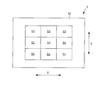
- FIG. 2 is a schematic plan view showing an overall configuration of an image sensor 5 mounted on the digital camera shown in FIG. 1.
- FIG. 3 is a partially enlarged view of one AF area 53 shown in FIG. 2.
- FIG. 4 is a diagram showing only phase difference detection pixels 52A and 52B in one pair row shown in FIG. 3; It is a figure for demonstrating the method to determine the direction where the reliability of the correlation calculation after addition becomes the maximum. It is a figure for demonstrating the method to determine the direction where the reliability of the correlation calculation after addition becomes the maximum.
- 4 is a flowchart for explaining an autofocus operation of the digital camera shown in FIG. 1. It is a figure which shows the modification of the image pick-up element 5 of the digital camera shown in FIG. It is a figure explaining a smart phone as an imaging device. It is an internal block diagram of the smart phone of FIG.
- FIG. 1 is a diagram showing a schematic configuration of a digital camera as an example of an imaging apparatus for explaining an embodiment of the present invention.
- the digital camera shown in FIG. 1 includes a lens device having an imaging lens 1 including a focus lens for adjusting the focus, a zoom lens, and the like, and an aperture 2.
- the lens device constitutes an imaging optical system.
- the lens device shown in FIG. 1 is fixed to the camera body, but may be exchangeable for another lens device.
- the imaging lens 1 only needs to include at least a focus lens.
- the focus lens may be a single focus lens that performs focus adjustment by moving the entire lens system.
- the digital camera includes a CCD type or CMOS type imaging device 5 that images a subject through a lens device, and an analog signal processing unit 6 that performs analog signal processing such as correlated double sampling processing connected to the output of the imaging device 5. And an A / D conversion circuit 7 for converting an analog signal output from the analog signal processing unit 6 into a digital signal.
- the analog signal processing unit 6 and the A / D conversion circuit 7 are controlled by the system control unit 11.
- the analog signal processing unit 6 and the A / D conversion circuit 7 may be built in the image sensor 5.
- a system control unit 11 that performs overall control of the entire electric control system of the digital camera controls the lens driving unit 8 to drive a focus lens included in the imaging lens 1 to focus on a main subject, or to perform imaging. The position of the zoom lens included in the lens 1 is adjusted. Further, the system control unit 11 adjusts the exposure amount by controlling the aperture amount of the aperture 2 via the aperture drive unit 9.
- system control unit 11 drives the imaging device 5 via the imaging device driving unit 10 and outputs the subject image captured through the imaging lens 1 as a captured image signal.
- An instruction signal from the user is input to the system control unit 11 through the operation unit 14.
- This instruction signal includes an instruction signal for instructing execution of focusing control of the imaging optical system.
- the electric control system of the digital camera includes an interpolation calculation and a gamma correction for the main memory 16, the memory control unit 15 connected to the main memory 16, and the captured image signal output from the A / D conversion circuit 7.
- a digital signal processing unit 17 that performs calculation and RGB / YC conversion processing to generate captured image data, a phase difference AF processing unit 19, and an external memory control unit 20 to which a detachable recording medium 21 is connected;
- a display control unit 22 to which a display unit 23 mounted on the back of the camera or the like is connected.
- the memory control unit 15, the digital signal processing unit 17, the phase difference AF processing unit 19, the external memory control unit 20, and the display control unit 22 are connected to each other by a control bus 24 and a data bus 25. Controlled by command.
- FIG. 2 is a schematic plan view showing the overall configuration of the image sensor 5 mounted on the digital camera shown in FIG.
- the imaging element 5 has an imaging surface 50 on which a large number of pixels arranged two-dimensionally in the X direction and the Y direction orthogonal to the X direction.
- nine AF areas 53 which are areas to be focused, are set in the example of FIG.
- the AF area 53 is an area including imaging pixels and phase difference detection pixels as pixels.
- the imaging pixels are arranged in the portion of the imaging surface 50 excluding the AF area 53.
- the AF area 53 may be provided on the imaging surface 50 without a gap.
- FIG. 3 is an enlarged view of one AF area 53 shown in FIG.
- pixels 51 are two-dimensionally arranged.
- Each pixel 51 includes a photoelectric conversion unit such as a photodiode and a color filter formed above the photoelectric conversion unit.
- a pixel 51 (also referred to as an R pixel 51) including a color filter (R filter) that transmits red light is marked with “R” and includes a color filter (G filter) that transmits green light.
- the pixel 51 (also referred to as G pixel 51) is given a letter “G”
- the pixel 51 (also referred to as B pixel 51) including a color filter (B filter) that transmits blue light is given a letter “B”. It is attached.
- the color filter array is a Bayer array over the entire imaging surface 50.
- phase difference detection pixels 52A and 52B part of the G pixel 51 (the shaded pixels in FIG. 3) are phase difference detection pixels 52A and 52B.
- each G pixel 51 in the third, seventh, and eleventh pixel rows from the top is a phase difference detection pixel 52A.
- the G pixel 51 of the same color closest to the column direction Y with respect to each phase difference detection pixel 52A is the phase difference detection pixel 52B.
- a pair of rows is formed by all the phase difference detection pixels 52A in an arbitrary row and the same color phase difference detection pixels 52B closest to the column direction Y for each of all the phase difference detection pixels 52A.
- the In FIG. 3, the pair rows PL1, PL2, and PL3 are arranged in the Y direction in the AF area 53, but the AF area 53 may have a plurality of pair rows.
- FIG. 4 is a diagram showing only the phase difference detection pixels 52A and 52B in one pair row shown in FIG.
- the phase difference detection pixel 52A receives a light beam that has passed through one divided area of the pupil area of the imaging lens 1 divided in one direction (X direction in the example of FIG. 3), and detects a signal corresponding to the amount of light received. It is a 1st signal detection part.
- the phase difference detection pixel 52B is a second signal detection unit that receives a light beam that has passed through the other divided region of the pupil region of the imaging lens 1 and detects a signal corresponding to the amount of received light.
- the plurality of pixels 51 other than the phase difference detection pixels 52A and 52B are imaging pixels.
- the imaging pixel receives a light beam that has passed through both of the two divided regions of the pupil region of the imaging lens 1 and detects a signal corresponding to the amount of received light.
- a light shielding film is provided above the photoelectric conversion unit of each pixel 51, and an opening that defines a light receiving area of the photoelectric conversion unit is formed in the light shielding film.
- the center of the opening of the imaging pixel 51 coincides with the center of the photoelectric conversion unit of the imaging pixel 51.
- the center of the opening (outlined portion in FIG. 4) of the phase difference detection pixel 52A is eccentric to the right side with respect to the center of the photoelectric conversion unit of the phase difference detection pixel 52A.
- the center of the opening (outlined portion in FIG. 4) of the phase difference detection pixel 52B is decentered to the left with respect to the center of the photoelectric conversion unit of the phase difference detection pixel 52B.
- the right direction here is one direction of the X direction shown in FIG. 3, and the left direction is the other direction of the X direction.
- FIG. 5 is a diagram showing a cross-sectional configuration in the X direction of the phase difference detection pixel 52A. As shown in FIG. 5, in the phase difference detection pixel 52A, the opening c is eccentric to the right with respect to the photoelectric conversion unit (PD).
- PD photoelectric conversion unit
- the pixel group including the phase difference detection pixels 52A in an arbitrary row, and the phase difference detection pixels 52B arranged at the same distance in one direction with respect to the phase difference detection pixels 52A of the pixel group.
- the phase difference in the row direction X in the image captured by each of these two pixel groups can be detected.
- the phase difference AF processing unit 19 shown in FIG. 1 generates the defocus amount by one of the following two methods according to the brightness of the subject.
- the phase difference AF processing unit 19 functions as a defocus amount generation unit.
- the phase difference AF processing unit 19 detects detection signal groups of the phase difference detection pixels 52A and the phase difference detection pixels 52B for each pair row in the AF area 53 selected by the user operation or the like from the nine AF areas 53.
- the correlation between the images is calculated, and a phase difference that is a relative positional shift amount between the image captured by the phase difference detection pixel 52A and the image captured by the phase difference detection pixel 52B is calculated.
- the phase difference AF processing unit 19 defocuss the amount of movement of the focus lens necessary for matching the imaging surface of the main subject with the imaging lens 1 with the imaging surface 50 of the imaging device 5.
- a quantity Dfr is generated.
- the phase difference AF processing unit 19 averages the defocus amount Dfr calculated for each pair row, and notifies the system control unit 11 of the defocus amount Df obtained by averaging.
- the phase difference AF processing unit 19 includes a plurality of phase difference detection pixels 52A (first pixels) arranged in the X direction in any pair row. And a detection signal of the phase difference detection pixels 52A in the other paired rows in the crossing direction intersecting the X direction for each of the plurality of phase difference detection pixels 52A.
- a first addition process is performed to add.
- phase difference AF processing unit 19 detects a phase difference detection pixel 52B (also referred to as a second addition reference pixel group) that forms a pair with each phase difference detection pixel 52A of the addition reference pixel group in the arbitrary pair row.
- a second addition process is performed in which the signal and the detection signal of the phase difference detection pixel 52B in another pair row in the crossing direction are added to the phase difference detection pixel 52B.
- the phase difference AF processing unit 19 calculates a correlation between the detection signal group of the phase difference detection pixel 52A obtained by the first addition process and the detection signal group of the phase difference detection pixel 52B obtained by the second addition process. (Referred to as addition correlation calculation), a defocus amount Df1 is generated from the result of the addition correlation calculation, and the generated defocus amount Df1 is notified to the system control unit 11.
- the phase difference AF processing unit 19 divides the selected AF area 53 into blocks in the Y direction, and adds the detection signals of the phase difference detection pixels 52A and 52B in a plurality of pair rows in the block for each block.
- the addition correlation calculation may be performed, and the defocus amount Df1 may be generated from the result of the addition correlation calculation.
- the phase difference AF processing unit 19 generates the defocus amount Df2 using the defocus amounts Df1 generated for the plurality of blocks (for example, by averaging the plurality of defocus amounts Df1), and the defocus amount Df2 May be notified to the system control unit 11.
- the phase difference AF processing unit 19 selects and sets one of a plurality of settable directions as the intersecting direction.
- the plurality of directions that can be set pass through any of the phase difference detection pixels 52A of the first addition reference pixel group and pass through the phase difference detection pixels 52A of each other pair row in the AF area 53. This is the direction in which the straight line extends.
- the phase difference AF processing unit 19 has a direction in which the reliability of the result of the addition correlation calculation is maximized when both of the settable directions are set as the crossing directions as described above. Is determined from among the plurality of directions, and the determined direction is selected and set.
- the phase difference AF processing unit 19 functions as a direction determination unit.
- the phase difference AF processing unit 19 calculates the defocus amount Df1 from the result of performing the addition correlation calculation with the maximum reliability direction set to the crossing direction.
- FIG. 6 is a diagram for explaining a method of determining the direction in which the reliability of the addition correlation calculation is maximized.
- FIG. 6 shows the AF area 53 shown in FIG.
- phase difference detection pixels 52A a plurality of phase difference detection pixels 52A (pixels surrounded by a thick frame in the figure) arranged in the X direction in the uppermost pair row PL1 are defined as a first addition reference pixel group, and the plurality of phase differences.
- a phase difference detection pixel 52B (a pixel surrounded by a thick frame in the drawing) that forms a pair with each of the detection pixels 52A is defined as a second addition reference pixel group.
- the phase difference AF processing unit 19 detects the detection signal of each phase difference detection pixel 52A in the first addition reference pixel group, and the phase difference detection pixels in the pair row PL2 in the direction D1 with respect to each phase difference detection pixel 52A.
- the detection signal of 52A and the detection signal of the phase difference detection pixel 52A in the pair row PL3 in the direction D1 are added.
- the detection signal group of the phase difference detection pixel 52A after the addition is SAd1.
- phase difference AF processing unit 19 detects the detection signal of each phase difference detection pixel 52B of the second addition reference pixel group and the phase difference detection of the pair row PL2 in the direction D1 with respect to each of the phase difference detection pixels 52B.
- the detection signal for the pixel for use 52B and the detection signal for the phase difference detection pixel 52B for the pair row PL3 in the direction D1 are added.
- the detection signal group of the phase difference detection pixel 52B after the addition is SBd1.
- the phase difference AF processing unit 19 detects the detection signal of each phase difference detection pixel 52A in the first addition reference pixel group and the phase difference of the pair row PL2 in the direction D2 with respect to each phase difference detection pixel 52A.
- the detection signal of the detection pixel 52A and the detection signal of the phase difference detection pixel 52A in the pair row PL3 in the direction D2 are added.
- the detection signal group of the phase difference detection pixel 52A after the addition is SAd2.
- phase difference AF processing unit 19 detects the detection signal of each phase difference detection pixel 52B of the second addition reference pixel group and the phase difference detection of the pair row PL2 in the direction D2 with respect to each of the phase difference detection pixels 52B.
- the detection signal of the pixel for use 52B and the detection signal of the phase difference detection pixel 52B for the pair row PL3 in the direction D2 are added.
- the detection signal group of the phase difference detection pixel 52B after the addition is SBd2.
- the phase difference AF processing unit 19 detects the detection signal of each phase difference detection pixel 52A of the first addition reference pixel group and the phase difference of the pair row PL2 in the direction D3 with respect to each phase difference detection pixel 52A.
- the detection signal of the detection pixel 52A and the detection signal of the phase difference detection pixel 52A in the pair row PL3 in the direction D3 are added.
- the detection signal group of the phase difference detection pixel 52A after the addition is SAd3.
- phase difference AF processing unit 19 detects the detection signal of each phase difference detection pixel 52B of the second addition reference pixel group and the phase difference detection of the pair row PL2 in the direction D3 with respect to each of the phase difference detection pixels 52B.
- the detection signal of the pixel for use 52B and the detection signal of the phase difference detection pixel 52B for the pair row PL3 in the direction D3 are added.
- the detection signal group of the phase difference detection pixel 52B after the addition is SBd3.
- the phase difference AF processing unit 19 performs a correlation calculation with the detection signal group SAd1 and the detection signal group SBd1, performs a correlation calculation with the detection signal group SAd2 and the detection signal group SBd2, and performs a correlation calculation with the detection signal group SAd3 and the detection signal group SBd3. I do.
- the correlation calculation is as follows when one detection signal group is A [1]... A [k], the other detection signal is B [1]... B [k], and these two data are shifted by “d”.
- the area S [d] surrounded by the two data waveforms obtained by the equation (1) is obtained.
- the area S [d] indicates the correlation amount between the two detection signal groups, and the smaller the area S [d], the higher the coincidence between the two detection signal groups.
- the phase difference AF processing unit 19 uses the minimum value of S [d], which is the result of the correlation calculation between the detection signal group SAd1 and the detection signal group SBd1, and the result of the correlation calculation between the detection signal group SAd2 and the detection signal group SBd2.
- the minimum value of a certain S [d] is compared with the minimum value of S [d] that is the result of the correlation calculation between the detection signal group SAd3 and the detection signal group SBd3. Then, of the directions D1, D2, and D3, the direction in which the minimum value of S [d] is obtained is determined as the direction with the highest reliability of the result of the addition correlation calculation.
- the addition correlation calculation is performed for each of the three directions D1, D2, and D3.
- a plurality of directions may be set. If the standard orientation of the digital camera is when the X direction is perpendicular to the gravity direction, the subject has many edges extending in the Y direction, so a plurality of directions including at least the direction D1 and the direction intersecting the direction D1 are set. It is good to do.
- FIG. 7 is a flowchart for explaining the autofocus operation of the digital camera shown in FIG.
- the system control unit 11 starts displaying a live view image (step S1).
- the system control unit 11 repeatedly performs control to display an image based on captured image data obtained by capturing an image of a subject with the image sensor 5 on the display unit 23.
- a focus control execution instruction for the imaging optical system (hereinafter referred to as an autofocus execution instruction, which is referred to as an autofocus execution instruction in the drawing) by a half-press operation of a shutter button included in the operation unit 14 or the like (Step S2: YES)
- the system control unit 11 updates the latest image signal (hereinafter referred to as the captured image signal) among the captured image signals obtained at the time when the autofocus execution instruction is given.
- the brightness of the subject imaged by the image sensor 5 is determined using Ga). For example, the system control unit 11 obtains the average or integrated value of the luminance values of the captured image signal Ga as the brightness.
- step S3: YES If the calculated brightness is less than or equal to the threshold (step S3: YES), the system control unit 11 causes the phase difference AF processing unit 19 to perform step S4, and if the calculated brightness exceeds the threshold ( Step S3: NO), the phase difference AF processing unit 19 performs the process of Step S9.
- the phase difference AF processing unit 19 includes the phase difference detection pixels 52 ⁇ / b> A and the phase difference detection pixels in each of the pair rows PL ⁇ b> 1, PL ⁇ b> 2, and PL ⁇ b> 3 of the selected AF area 53 in the captured image signal Ga.
- the correlation calculation is performed between the detection signal groups 52B, and the defocus amount Dfr is calculated for each of the pair rows PL1, PL2, and PL3. Further, the phase difference AF processing unit 19 calculates the average value of the defocus amount Dfr as the final defocus amount Df, and notifies the system control unit 11 of the defocus amount Df.
- the system control unit 11 moves the focus lens by an amount corresponding to the defocus amount Df based on the defocus amount Df notified from the phase difference AF processing unit 19 (step S10), and completes autofocus.
- step S4 the phase difference AF processing unit 19 determines the direction in which the reliability of the result of the addition correlation calculation is maximized by the method described with reference to FIG.
- the phase difference AF processing unit 19 sets a plurality of phase difference detection pixels 52A included in an arbitrary pair row of the selected AF area 53 as a first addition reference pixel group, and the plurality of phase difference detection pixels.
- Each detection signal of 52A is added to the detection signal of the phase difference detection pixels 52A in the other paired rows in the direction determined in step S4 with respect to each of the phase difference detection pixels 52A (step S5). .
- phase difference AF processing unit 19 sets the phase difference detection pixel 52B paired with each phase difference detection pixel 52A of the first addition reference pixel group as the second addition reference pixel group, and this phase difference detection pixel.
- the detection signal of 52B and the detection signal of the phase difference detection pixels 52B in the other paired rows in the direction determined in step S4 are added to the phase difference detection pixels 52B (step S6).
- the phase difference AF processing unit 19 calculates a correlation between the detection signal group of the phase difference detection pixel 52A obtained by addition in step S5 and the detection signal group of the phase difference detection pixel 52A obtained by addition in step S6. And the defocus amount Df1 is calculated from the result of this correlation calculation (step S7).
- step S7 the result of the correlation calculation in step S7 is also obtained when the direction is determined in step S4. For this reason, steps S5 and S6 are omitted, and in step S7, the defocus amount Df1 may be calculated from the result of the addition correlation calculation obtained in step S4.
- step S7 When the defocus amount Df1 is calculated in step S7, this is notified to the system control unit 11. Based on the defocus amount Df1, the system control unit 11 moves the focus lens by an amount corresponding to the defocus amount Df1 (step S8), and the autofocus is completed.
- the system control unit 11 functions as an in-focus control unit.
- the correlation calculation is performed after adding the detection signals of the phase difference detection pixels 52A (52B) in a plurality of rows. It is possible to prevent a reduction in focus amount calculation accuracy.
- the detection signal is added between the phase difference detection pixels in the direction in which the reliability of the result of the addition correlation calculation is maximized, the detection signal is always added between the phase difference detection pixels in the same direction. In comparison, the defocus amount calculation accuracy can be improved.
- step S4 of FIG. 7 the phase difference AF processing unit 19 performs the addition correlation calculation by setting the crossing direction to each of a plurality of directions, and by comparing the results of the addition correlation calculation for each of the plurality of directions, The direction in which the reliability of the addition correlation calculation is maximized is determined.
- the phase difference AF processing unit 19 may determine the direction in which the contrast of the subject image formed in the selected AF area 53 is minimum as the maximum reliability direction.
- a small contrast in a direction means that there are few or no edges intersecting that direction. For this reason, the reliability of the result of performing the addition correlation calculation in that direction also increases.
- the first imaging pixel group including the imaging pixels 51 obliquely lower left with respect to the phase difference detection pixels 52A in the pair row PL1 and the phase difference detection pixels 52A in the pair row PL2
- a second imaging pixel group consisting of imaging pixels 51 diagonally lower left
- a third imaging pixel consisting of imaging pixels 51 diagonally lower left relative to each phase difference detection pixel 52A of the pair row PL3. Focus on groups.
- the phase difference AF processing unit 19 includes the imaging pixels 51 of the first imaging pixel group, and the imaging pixels 51 and 3 of the second imaging pixel group in the direction D1 with respect to the imaging pixels 51.
- the difference between the detection signals is calculated between the adjacent image pickup pixels 51 and the image pickup pixels 51 of the image pickup pixel group.
- the integrated value of the difference is calculated as the contrast in the direction D1 of the subject image formed in the AF area 53.
- the phase difference AF processing unit 19 may calculate the contrast in the same manner by changing the direction D1 to the directions D2 and D3, and set the direction in which the contrast is the smallest as the maximum reliability direction.
- the phase difference AF processing unit 19 sets the pair of the phase difference detection pixels 52A (or 52B) in the pair row PL1 of the AF area 53 and the phase difference detection pixels 52A (or 52B) in the direction D1.
- the phase difference detection pixels 52A (or 52B) in the rows PL2 and PL3 calculate the difference in detection signal between the adjacent phase difference detection pixels 52A (or 52B).
- the integrated value of the difference is calculated as the contrast in the direction D1 of the subject image formed in the AF area 53.
- the phase difference AF processing unit 19 may calculate the contrast in the same manner by changing the direction D1 to the directions D2 and D3, and the direction with the smallest contrast may be set as the maximum reliability direction.
- the detection signal of the phase difference detection pixel 52A or the phase difference detection pixel 52B is used for the calculation of the contrast, compared with the method using the detection signal of the imaging pixel 51 for the calculation of the contrast. Therefore, the determination accuracy in the maximum reliability direction can be improved.
- the phase difference AF processing unit 19 may determine the direction closest to the direction of gravity among the settable directions as the maximum reliability direction.
- a gravitational direction detection unit for detecting the gravitational direction of an electronic level or the like is provided in the digital camera of FIG. Then, the phase difference AF processing unit 19 determines the gravity direction detected by the gravity direction detection unit in step S4 of FIG. 7 as the direction in which the reliability of the addition correlation calculation is maximized. By doing in this way, the amount of calculation can be reduced and energy saving becomes possible.
- the main memory 16 of the digital camera stores the imaging scene and information on the direction in which the reliability is maximized in association with each other.
- step S4 of FIG. 7 the phase difference AF processing unit 19 acquires information on the direction associated with the imaging scene from the set imaging scene, and the reliability of the addition correlation calculation is maximized for this direction. It is determined as a direction. By doing in this way, the amount of calculation can be reduced and energy saving becomes possible.
- step S4 the processing after step S4 is performed when the subject is dark.
- the addition of the detection signal of the phase difference detection pixel is necessary in an imaging situation where the detection signal level of the phase difference detection pixels 52A and 52B is low, and is not limited to when the subject is dark.
- step S4 when the angle of light incident on the image sensor 5 increases and the light incident on the phase difference detection pixels 52A and 52B decreases (during wide-angle imaging), the processing from step S4 onward may be performed. Alternatively, when the detection signal level of the phase difference detection pixels 52A and 52B is small, the processing after step S4 may be performed.
- the image sensor 5 may be configured to have a plurality of pairs of the first signal detection unit and the second signal detection unit, and is not limited to the configuration illustrated in FIGS.
- all the pixels included in the image sensor 5 are the imaging pixels 51, each of the imaging pixels 51 is divided into two, one division area is the phase difference detection pixel 52A, and the other division area is the position.
- the phase difference detection pixel 52B may be used.
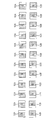
- FIG. 8 is a diagram illustrating a configuration in which all pixels included in the image sensor 5 are set as the imaging pixels 51 and each imaging pixel 51 is divided into two.
- the imaging pixel 51 given R in the imaging element 5 is divided into two, and the divided two are designated as a phase difference detection pixel r1 and a phase difference detection pixel r2, respectively.
- the imaging pixel 51 with G in the imaging element 5 is divided into two, and the two divided pixels are used as a phase difference detection pixel g1 and a phase difference detection pixel g2, respectively.
- the imaging pixel 51 with B in the imaging device 5 is divided into two, and the two divided pixels are used as a phase difference detection pixel b1 and a phase difference detection pixel b2, respectively.
- phase difference detection pixels r1, g1, and b1 are each a first signal detection unit
- the phase difference detection pixels r2, g2, and b2 are each a second signal detection unit. Signals can be read independently from the first signal detector and the second signal detector.
- a normal imaging signal having no phase difference can be obtained.
- all the pixels can be used as both the phase difference detection pixel and the imaging pixel.
- a pair row is configured by the phase difference detection pixels g1 and g2 in the first row
- a pair row is configured by the phase difference detection pixels g1 and g2 in the third row.
- the phase difference detection pixels g1 and g2 in the eyes constitute a pair row
- the phase difference detection pixels g1 and g2 in the seventh row constitute a pair row.
- a digital camera is taken as an example of the imaging device, but an embodiment of a smartphone with a camera as the imaging device will be described below.
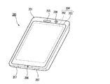
- FIG. 9 shows an appearance of a smartphone 200 that is an embodiment of the imaging apparatus of the present invention.
- a smartphone 200 illustrated in FIG. 9 includes a flat housing 201, and a display input in which a display panel 202 as a display unit and an operation panel 203 as an input unit are integrated on one surface of the housing 201. Part 204 is provided.
- Such a housing 201 includes a speaker 205, a microphone 206, an operation unit 207, and a camera unit 208.
- the configuration of the housing 201 is not limited thereto, and for example, a configuration in which the display unit and the input unit are independent can be employed, or a configuration having a folding structure and a slide mechanism can be employed.
- FIG. 10 is a block diagram showing a configuration of the smartphone 200 shown in FIG.
- the main components of the smartphone include a wireless communication unit 210, a display input unit 204, a call unit 211, an operation unit 207, a camera unit 208, a storage unit 212, and an external input / output unit. 213, a GPS (Global Positioning System) receiving unit 214, a motion sensor unit 215, a power supply unit 216, and a main control unit 220.
- a wireless communication function for performing mobile wireless communication via a base station device BS (not shown) and a mobile communication network NW (not shown) is provided.
- the wireless communication unit 210 performs wireless communication with the base station apparatus BS accommodated in the mobile communication network NW according to an instruction from the main control unit 220. Using this wireless communication, transmission and reception of various file data such as audio data and image data, e-mail data, and reception of Web data and streaming data are performed.
- the display input unit 204 controls the main control unit 220 to display images (still images and moving images), character information, and the like to visually transmit information to the user and to detect user operations on the displayed information.
- a so-called touch panel which includes a display panel 202 and an operation panel 203.
- the display panel 202 uses an LCD (Liquid Crystal Display), an OELD (Organic Electro-Luminescence Display), or the like as a display device.
- LCD Liquid Crystal Display
- OELD Organic Electro-Luminescence Display
- the operation panel 203 is a device that is placed so that an image displayed on the display surface of the display panel 202 is visible and detects one or more coordinates operated by a user's finger or stylus.
- a detection signal generated due to the operation is output to the main control unit 220.
- the main control unit 220 detects an operation position (coordinates) on the display panel 202 based on the received detection signal.
- the display panel 202 and the operation panel 203 of the smartphone 200 exemplified as an embodiment of the imaging apparatus of the present invention integrally form a display input unit 204.
- the arrangement 203 covers the display panel 202 completely.
- the operation panel 203 may have a function of detecting a user operation even in an area outside the display panel 202.
- the operation panel 203 includes a detection area (hereinafter referred to as a display area) for an overlapping portion that overlaps the display panel 202 and a detection area (hereinafter, a non-display area) for an outer edge portion that does not overlap the other display panel 202. May be included).
- the operation panel 203 may include two sensitive areas of the outer edge portion and the other inner portion. Further, the width of the outer edge portion is appropriately designed according to the size of the housing 201 and the like.
- the position detection method employed in the operation panel 203 include a matrix switch method, a resistance film method, a surface acoustic wave method, an infrared method, an electromagnetic induction method, a capacitance method, and the like. You can also
- the call unit 211 includes a speaker 205 and a microphone 206, converts user's voice input through the microphone 206 into voice data that can be processed by the main control unit 220, and outputs the voice data to the main control unit 220. 210 or the audio data received by the external input / output unit 213 is decoded and output from the speaker 205.
- the speaker 205 can be mounted on the same surface as the display input unit 204 and the microphone 206 can be mounted on the side surface of the housing 201.
- the operation unit 207 is a hardware key using a key switch or the like, and receives an instruction from the user.
- the operation unit 207 is mounted on the side surface of the housing 201 of the smartphone 200 and is turned on when pressed with a finger or the like, and turned off when the finger is released with a restoring force such as a spring. It is a push button type switch.
- the storage unit 212 includes a control program and control data of the main control unit 220, application software, address data that associates the name and telephone number of a communication partner, transmitted / received e-mail data, Web data downloaded by Web browsing, The downloaded content data is stored, and streaming data and the like are temporarily stored.
- the storage unit 212 includes an internal storage unit 217 built in the smartphone and an external storage unit 218 having a removable external memory slot.
- Each of the internal storage unit 217 and the external storage unit 218 constituting the storage unit 212 includes a flash memory type (hard memory type), a hard disk type (hard disk type), a multimedia card micro type (multimedia card micro type), This is realized using a storage medium such as a card type memory (for example, MicroSD (registered trademark) memory), a RAM (Random Access Memory), a ROM (Read Only Memory), or the like.
- a flash memory type hard memory type
- hard disk type hard disk type
- multimedia card micro type multimedia card micro type
- a storage medium such as a card type memory (for example, MicroSD (registered trademark) memory), a RAM (Random Access Memory), a ROM (Read Only Memory), or the like.
- the external input / output unit 213 serves as an interface with all external devices connected to the smartphone 200, and communicates with other external devices (for example, universal serial bus (USB), IEEE 1394, etc.) or a network.
- external devices for example, universal serial bus (USB), IEEE 1394, etc.
- a network for example, Internet, wireless LAN, Bluetooth (registered trademark), RFID (Radio Frequency Identification), Infrared Data Association (IrDA) (registered trademark), UWB (Ultra Wideband) (registered trademark) ZigBee) (registered trademark, etc.) for direct or indirect connection.
- an external device connected to the smartphone 200 for example, a wired / wireless headset, a wired / wireless external charger, a wired / wireless data port, a memory card (Memory card) connected via a card socket, or a SIM (Subscriber).
- Identity Module Card / UIM (User Identity Module Card) card external audio / video equipment connected via audio / video I / O (Input / Output) terminal, external audio / video equipment connected wirelessly, yes / no
- the external input / output unit 213 transmits data received from such an external device to each component inside the smartphone 200, or allows the data inside the smartphone 200 to be transmitted to the external device. Can do.
- the GPS receiving unit 214 receives GPS signals transmitted from the GPS satellites ST1 to STn in accordance with instructions from the main control unit 220, executes positioning calculation processing based on the received GPS signals, and calculates the latitude of the smartphone 200 Detect the position consisting of longitude and altitude.
- the GPS reception unit 214 can acquire position information from the wireless communication unit 210 or the external input / output unit 213 (for example, a wireless LAN), the GPS reception unit 214 can also detect the position using the position information.
- the motion sensor unit 215 includes, for example, a three-axis acceleration sensor, and detects the physical movement of the smartphone 200 in accordance with an instruction from the main control unit 220. By detecting the physical movement of the smartphone 200, the moving direction and acceleration of the smartphone 200 are detected. The detection result is output to the main control unit 220.
- the power supply unit 216 supplies power stored in a battery (not shown) to each unit of the smartphone 200 in accordance with an instruction from the main control unit 220.
- the main control unit 220 includes a microprocessor, operates according to a control program and control data stored in the storage unit 212, and controls each unit of the smartphone 200 in an integrated manner.
- the main control unit 220 includes a mobile communication control function that controls each unit of the communication system and an application processing function in order to perform voice communication and data communication through the wireless communication unit 210.
- the application processing function is realized by the main control unit 220 operating according to the application software stored in the storage unit 212.
- Examples of the application processing function include an infrared communication function for controlling the external input / output unit 213 to perform data communication with the opposite device, an e-mail function for transmitting / receiving e-mails, and a web browsing function for browsing web pages. .
- the main control unit 220 has an image processing function such as displaying video on the display input unit 204 based on image data (still image or moving image data) such as received data or downloaded streaming data.
- the image processing function is a function in which the main control unit 220 decodes the image data, performs image processing on the decoding result, and displays an image on the display input unit 204.
- the main control unit 220 executes display control for the display panel 202 and operation detection control for detecting a user operation through the operation unit 207 and the operation panel 203.
- the main control unit 220 displays an icon for starting application software, a software key such as a scroll bar, or a window for creating an e-mail.
- a software key such as a scroll bar, or a window for creating an e-mail.
- the scroll bar refers to a software key for accepting an instruction to move the display portion of a large image that does not fit in the display area of the display panel 202.
- the main control unit 220 detects a user operation through the operation unit 207 or accepts an operation on the icon or an input of a character string in the input field of the window through the operation panel 203. Or a display image scroll request through a scroll bar.
- the main control unit 220 causes the operation position with respect to the operation panel 203 to overlap with the display panel 202 (display area) or other outer edge part (non-display area) that does not overlap with the display panel 202.
- a touch panel control function for controlling the sensitive area of the operation panel 203 and the display position of the software key.
- the main control unit 220 can also detect a gesture operation on the operation panel 203 and execute a preset function in accordance with the detected gesture operation.
- Gesture operation is not a conventional simple touch operation, but an operation that draws a trajectory with a finger or the like, designates a plurality of positions at the same time, or combines these to draw a trajectory for at least one of a plurality of positions. means.
- the camera unit 208 includes configurations other than the external memory control unit 20, the recording medium 21, the display control unit 22, the display unit 23, and the operation unit 14 in the digital camera shown in FIG.
- the captured image data generated by the camera unit 208 can be recorded in the storage unit 212 or output through the input / output unit 213 or the wireless communication unit 210.
- the camera unit 208 is mounted on the same surface as the display input unit 204, but the mounting position of the camera unit 208 is not limited thereto, and may be mounted on the back surface of the display input unit 204. .
- the camera unit 208 can be used for various functions of the smartphone 200.
- an image acquired by the camera unit 208 can be displayed on the display panel 202, or the image of the camera unit 208 can be used as one of operation inputs of the operation panel 203.
- the GPS receiving unit 214 detects a position
- the position can be detected with reference to an image from the camera unit 208.
- the optical axis direction of the camera unit 208 of the smartphone 200 is determined without using the triaxial acceleration sensor or in combination with the triaxial acceleration sensor. It is also possible to determine the current usage environment.
- the image from the camera unit 208 can also be used in the application software.
- the position information acquired by the GPS receiver 214 to the image data of the still image or the moving image, the voice information acquired by the microphone 206 (the text information may be converted into voice information by the main control unit or the like), Posture information and the like acquired by the motion sensor unit 215 can be added and recorded in the storage unit 212, or can be output through the input / output unit 213 and the wireless communication unit 210.
- the image sensor 5 is used as the image sensor of the camera unit 208, and the main control unit 220 performs the processing described with reference to FIG. Even when the distance is low, high-precision focusing control is possible regardless of the subject.
- the disclosed imaging apparatus includes a first signal detection unit that detects a signal corresponding to a light beam that has passed through one of the pupil regions of the imaging optical system that is divided in one direction, and the other divided region.
- An image pickup having a pair of rows of second signal detectors that detect a signal corresponding to the light beam that has passed through the one direction, and a plurality of the pair rows arranged in a direction orthogonal to the one direction.
- a plurality of detection signals obtained by adding the detection signals of the first signal detection units of the other pair rows of the area in the crossing direction intersecting with one direction, and the plurality of detection signals of the arbitrary pair rows The second signal forming a pair with each of the first signal detectors A plurality of signals obtained by adding the detection signal of the signal detection unit and the detection signal of the second signal detection unit in the other pair row of the area in the crossing direction with respect to the second signal detection unit
- a defocus amount generation unit that generates a defocus amount from the result of correlation calculation with a detection signal of the signal, and a direction for determining a direction in which the reliability of the result of the correlation calculation is maximized among a plurality of directions as the crossing direction Focusing control of the imaging optical system is performed based on a defocus amount generated by the defocus amount generation unit based on a result of the
- the direction determination unit performs the correlation calculation by setting the intersecting direction to each of the plurality of directions, and by comparing the results of the correlation calculation for each of the plurality of directions, The direction in which the reliability is maximized may be determined.
- the direction determination unit may determine the direction in which the contrast of the subject image formed in the area is minimum as the direction in which the reliability is maximum.
- the direction determination unit includes each of the plurality of first signal detection units or the plurality of second signal detection units in the arbitrary pair row, and the plurality of first signal detections. Or each of the plurality of second signal detection units with the first signal detection unit or the second signal detection unit of the other pair row in the area in each of the plurality of directions.
- the contrast may be calculated by integrating the difference between detection signals of adjacent signal detection units.
- the direction determination unit may determine a direction closest to the direction of gravity among the plurality of directions as a direction in which the reliability is maximized.
- the focus control method of the disclosed imaging apparatus includes a first signal detection unit that detects a signal corresponding to a light beam that has passed through one of the divided regions of the imaging optical system divided in one direction, and , Having a pair row in which a plurality of pairs of second signal detectors for detecting a signal corresponding to the light beam that has passed through the other divided region are arranged in the one direction, and the pair row is in a direction orthogonal to the one direction Detection signals of the plurality of first signal detection units in any pair row in the area where the plurality of pair rows are arranged, and the plurality of first signals output from a plurality of image pickup devices arranged A plurality of detection signals obtained by adding the detection signals of the first signal detection units in the other pair rows of the area in the crossing direction intersecting the one direction with respect to each of the detection units; Each of the plurality of first signal detectors in any pair row The detection signal of the second signal detection unit forming a pair with the second signal detection unit and the detection of the second signal detection unit of the
- the present invention is highly convenient and effective when applied to a digital camera or the like.
Landscapes
- Physics & Mathematics (AREA)
- Engineering & Computer Science (AREA)
- Multimedia (AREA)
- Signal Processing (AREA)
- General Physics & Mathematics (AREA)
- Optics & Photonics (AREA)
- Computer Vision & Pattern Recognition (AREA)
- Spectroscopy & Molecular Physics (AREA)
- Studio Devices (AREA)
- Focusing (AREA)
- Automatic Focus Adjustment (AREA)
Abstract
L'invention porte sur un dispositif d'imagerie et sur un procédé de commande de focalisation, avec lesquels, même dans des cas dans lesquels les niveaux de signal de détection de pixels de détection de différence de phase sont faibles, la précision de commande de focalisation peut être améliorée, quel que soit l'objet. Une unité de traitement d'autofocalisation de différence de phase (19) génère une quantité de défocalisation (Df1) à partir du résultat d'un calcul de corrélation entre des signaux de détection, ledit résultat étant obtenu par l'addition : des signaux de détection d'une pluralité de pixels de détection de différence de phase (52A, 52B) dans une ligne de paires (PL1) dans une zone d'autofocalisation sélectionnée (53) ; et des signaux de détection de pixels de détection de différence de phase (52A, 52B) dans des lignes de paires (PL2, PL3) dans des directions sélectionnées, parmi une pluralité de directions, comme des directions d'intersection croisant des directions X de chacun de la pluralité précédemment mentionnée de pixels de détection de différence de phase (52A, 52B). Une unité de commande de système (11) effectue une commande de focalisation sur la base de la quantité de défocalisation (Df1).
Priority Applications (3)
| Application Number | Priority Date | Filing Date | Title |
|---|---|---|---|
| JP2016508455A JP5982601B2 (ja) | 2014-03-18 | 2014-12-17 | 撮像装置及び合焦制御方法 |
| CN201480075717.0A CN106030366B (zh) | 2014-03-18 | 2014-12-17 | 摄像装置及对焦控制方法 |
| US15/227,186 US9794472B2 (en) | 2014-03-18 | 2016-08-03 | Imaging device and focusing control method |
Applications Claiming Priority (2)
| Application Number | Priority Date | Filing Date | Title |
|---|---|---|---|
| JP2014-054992 | 2014-03-18 | ||
| JP2014054992 | 2014-03-18 |
Related Child Applications (1)
| Application Number | Title | Priority Date | Filing Date |
|---|---|---|---|
| US15/227,186 Continuation US9794472B2 (en) | 2014-03-18 | 2016-08-03 | Imaging device and focusing control method |
Publications (1)
| Publication Number | Publication Date |
|---|---|
| WO2015141084A1 true WO2015141084A1 (fr) | 2015-09-24 |
Family
ID=54144079
Family Applications (1)
| Application Number | Title | Priority Date | Filing Date |
|---|---|---|---|
| PCT/JP2014/083356 Ceased WO2015141084A1 (fr) | 2014-03-18 | 2014-12-17 | Dispositif d'imagerie, et procédé de commande de focalisation |
Country Status (4)
| Country | Link |
|---|---|
| US (1) | US9794472B2 (fr) |
| JP (1) | JP5982601B2 (fr) |
| CN (1) | CN106030366B (fr) |
| WO (1) | WO2015141084A1 (fr) |
Cited By (2)
| Publication number | Priority date | Publication date | Assignee | Title |
|---|---|---|---|---|
| JP2017076872A (ja) * | 2015-10-14 | 2017-04-20 | キヤノン株式会社 | 撮像素子 |
| WO2017175579A1 (fr) * | 2016-04-07 | 2017-10-12 | 富士フイルム株式会社 | Dispositif de commande de mise au point, dispositif de lentille, dispositif d'imagerie, procédé de commande de mise au point et programme de commande de mise au point |
Families Citing this family (9)
| Publication number | Priority date | Publication date | Assignee | Title |
|---|---|---|---|---|
| US10523860B2 (en) * | 2016-05-12 | 2019-12-31 | Canon Kabushiki Kaisha | Focus detection device, control method thereof, and image capture apparatus |
| JP6847669B2 (ja) * | 2017-01-10 | 2021-03-24 | オリンパス株式会社 | 撮像装置、撮像方法 |
| CN108337424B (zh) * | 2017-01-17 | 2021-04-16 | 中兴通讯股份有限公司 | 一种相位对焦方法及其装置 |
| CN106921823B (zh) * | 2017-04-28 | 2019-09-17 | Oppo广东移动通信有限公司 | 图像传感器、摄像模组和终端设备 |
| US10423049B2 (en) | 2017-06-12 | 2019-09-24 | Qualcomm Incorporated | Systems and methods for enabling transmission of phase detection data |
| CN112866542B (zh) * | 2019-11-12 | 2022-08-12 | Oppo广东移动通信有限公司 | 追焦方法和装置、电子设备、计算机可读存储介质 |
| CN112866553B (zh) * | 2019-11-12 | 2022-05-17 | Oppo广东移动通信有限公司 | 对焦方法和装置、电子设备、计算机可读存储介质 |
| CN110933305B (zh) * | 2019-11-28 | 2021-07-20 | 维沃移动通信有限公司 | 电子设备及对焦方法 |
| KR102902548B1 (ko) * | 2020-02-04 | 2025-12-22 | 삼성전자주식회사 | 전자 장치 및 af 수행 방법 |
Citations (3)
| Publication number | Priority date | Publication date | Assignee | Title |
|---|---|---|---|---|
| JP2010152161A (ja) * | 2008-12-25 | 2010-07-08 | Canon Inc | 撮像装置 |
| JP2011135191A (ja) * | 2009-12-22 | 2011-07-07 | Canon Inc | 撮像装置及び画像処理装置 |
| JP2013186187A (ja) * | 2012-03-06 | 2013-09-19 | Nikon Corp | 焦点検出装置および撮像装置 |
Family Cites Families (15)
| Publication number | Priority date | Publication date | Assignee | Title |
|---|---|---|---|---|
| WO2008032820A1 (fr) * | 2006-09-14 | 2008-03-20 | Nikon Corporation | Élément et dispositif d'imagerie |
| JP5276371B2 (ja) * | 2008-07-09 | 2013-08-28 | キヤノン株式会社 | 撮像装置 |
| JP2010091943A (ja) * | 2008-10-10 | 2010-04-22 | Canon Inc | 撮像装置 |
| JP5543098B2 (ja) * | 2008-11-14 | 2014-07-09 | キヤノン株式会社 | 撮像装置 |
| US8570427B2 (en) * | 2009-01-28 | 2013-10-29 | Nikon Corporation | Image-capturing device having focus adjustment function, image creation method including focus adjustment function, and program product for image-capturing device having focus adjustment function |
| JP5664270B2 (ja) * | 2011-01-21 | 2015-02-04 | ソニー株式会社 | 撮像素子および撮像装置 |
| JP5473977B2 (ja) * | 2011-04-14 | 2014-04-16 | キヤノン株式会社 | 撮像装置およびカメラシステム |
| EP2762942B1 (fr) * | 2011-09-28 | 2016-11-23 | Fujifilm Corporation | Elément de capture d'image à semi-conducteurs, dispositif de capture d'image et procédé de commande de focalisation |
| KR20130038035A (ko) * | 2011-10-07 | 2013-04-17 | 삼성전자주식회사 | 촬상소자 |
| JP6131546B2 (ja) * | 2012-03-16 | 2017-05-24 | 株式会社ニコン | 画像処理装置、撮像装置および画像処理プログラム |
| JP5947601B2 (ja) | 2012-04-10 | 2016-07-06 | キヤノン株式会社 | 焦点検出装置、その制御方法および撮像装置 |
| JP6087674B2 (ja) * | 2013-02-27 | 2017-03-01 | キヤノン株式会社 | 撮像装置 |
| CN106062607B (zh) * | 2014-03-18 | 2018-09-25 | 富士胶片株式会社 | 摄像装置及对焦控制方法 |
| CN106062608B (zh) * | 2014-03-25 | 2018-07-31 | 富士胶片株式会社 | 摄像装置及对焦控制方法 |
| JP6630058B2 (ja) * | 2014-06-16 | 2020-01-15 | キヤノン株式会社 | 撮像装置、撮像装置の制御方法、及び、プログラム |
-
2014
- 2014-12-17 JP JP2016508455A patent/JP5982601B2/ja not_active Expired - Fee Related
- 2014-12-17 CN CN201480075717.0A patent/CN106030366B/zh active Active
- 2014-12-17 WO PCT/JP2014/083356 patent/WO2015141084A1/fr not_active Ceased
-
2016
- 2016-08-03 US US15/227,186 patent/US9794472B2/en not_active Expired - Fee Related
Patent Citations (3)
| Publication number | Priority date | Publication date | Assignee | Title |
|---|---|---|---|---|
| JP2010152161A (ja) * | 2008-12-25 | 2010-07-08 | Canon Inc | 撮像装置 |
| JP2011135191A (ja) * | 2009-12-22 | 2011-07-07 | Canon Inc | 撮像装置及び画像処理装置 |
| JP2013186187A (ja) * | 2012-03-06 | 2013-09-19 | Nikon Corp | 焦点検出装置および撮像装置 |
Cited By (5)
| Publication number | Priority date | Publication date | Assignee | Title |
|---|---|---|---|---|
| JP2017076872A (ja) * | 2015-10-14 | 2017-04-20 | キヤノン株式会社 | 撮像素子 |
| WO2017175579A1 (fr) * | 2016-04-07 | 2017-10-12 | 富士フイルム株式会社 | Dispositif de commande de mise au point, dispositif de lentille, dispositif d'imagerie, procédé de commande de mise au point et programme de commande de mise au point |
| JPWO2017175579A1 (ja) * | 2016-04-07 | 2019-02-14 | 富士フイルム株式会社 | 合焦制御装置、レンズ装置、撮像装置、合焦制御方法、合焦制御プログラム |
| US11256064B2 (en) | 2016-04-07 | 2022-02-22 | Fujifilm Corporation | Focusing control device, lens device, imaging device, focusing control method, focusing control program |
| US12253742B2 (en) | 2016-04-07 | 2025-03-18 | Fujifilm Corporation | Focusing control device, lens device, imaging device, focusing control method, focusing control program |
Also Published As
| Publication number | Publication date |
|---|---|
| CN106030366B (zh) | 2018-07-10 |
| US9794472B2 (en) | 2017-10-17 |
| JP5982601B2 (ja) | 2016-08-31 |
| CN106030366A (zh) | 2016-10-12 |
| US20160344922A1 (en) | 2016-11-24 |
| JPWO2015141084A1 (ja) | 2017-04-06 |
Similar Documents
| Publication | Publication Date | Title |
|---|---|---|
| JP5982601B2 (ja) | 撮像装置及び合焦制御方法 | |
| JP5542249B2 (ja) | 撮像素子及びこれを用いた撮像装置及び撮像方法 | |
| JP5799178B2 (ja) | 撮像装置及び合焦制御方法 | |
| JP6307526B2 (ja) | 撮像装置及び合焦制御方法 | |
| JP6028112B2 (ja) | 撮像装置及び合焦制御方法 | |
| JP5779726B2 (ja) | 撮像装置及び露出決定方法 | |
| JP5934843B2 (ja) | 撮像装置及び合焦制御方法 | |
| JP5872122B2 (ja) | 撮像装置及び合焦制御方法 | |
| WO2014155806A1 (fr) | Dispositif d'imagerie, et procédé de commande de focalisation | |
| JP5978411B2 (ja) | 撮像装置及び合焦制御方法 | |
| JP5982600B2 (ja) | 撮像装置及び合焦制御方法 | |
| WO2017057071A1 (fr) | Dispositif de commande de mise au point, procédé de commande de mise au point, programme de commande de mise au point, dispositif d'objectif, et dispositif d'imagerie | |
| JP5990665B2 (ja) | 撮像装置及び合焦制御方法 | |
| JP5542248B2 (ja) | 撮像素子及び撮像装置 | |
| JP6446599B2 (ja) | 合焦制御装置、レンズ装置、撮像装置、合焦制御方法、合焦制御プログラム | |
| WO2015146229A1 (fr) | Dispositif d'imagerie et procédé de commande de focalisation | |
| WO2015146228A1 (fr) | Dispositif d'imagerie et procédé de commande de mise au point |
Legal Events
| Date | Code | Title | Description |
|---|---|---|---|
| 121 | Ep: the epo has been informed by wipo that ep was designated in this application |
Ref document number: 14886492 Country of ref document: EP Kind code of ref document: A1 |
|
| ENP | Entry into the national phase |
Ref document number: 2016508455 Country of ref document: JP Kind code of ref document: A |
|
| NENP | Non-entry into the national phase |
Ref country code: DE |
|
| 122 | Ep: pct application non-entry in european phase |
Ref document number: 14886492 Country of ref document: EP Kind code of ref document: A1 |