WO2015141285A1 - ハイブリッド車両の制御装置 - Google Patents
ハイブリッド車両の制御装置 Download PDFInfo
- Publication number
- WO2015141285A1 WO2015141285A1 PCT/JP2015/052329 JP2015052329W WO2015141285A1 WO 2015141285 A1 WO2015141285 A1 WO 2015141285A1 JP 2015052329 W JP2015052329 W JP 2015052329W WO 2015141285 A1 WO2015141285 A1 WO 2015141285A1
- Authority
- WO
- WIPO (PCT)
- Prior art keywords
- engine
- clutch
- vehicle
- gear ratio
- mode
- Prior art date
- Legal status (The legal status is an assumption and is not a legal conclusion. Google has not performed a legal analysis and makes no representation as to the accuracy of the status listed.)
- Ceased
Links
Images



Classifications
-
- B—PERFORMING OPERATIONS; TRANSPORTING
- B60—VEHICLES IN GENERAL
- B60W—CONJOINT CONTROL OF VEHICLE SUB-UNITS OF DIFFERENT TYPE OR DIFFERENT FUNCTION; CONTROL SYSTEMS SPECIALLY ADAPTED FOR HYBRID VEHICLES; ROAD VEHICLE DRIVE CONTROL SYSTEMS FOR PURPOSES NOT RELATED TO THE CONTROL OF A PARTICULAR SUB-UNIT
- B60W20/00—Control systems specially adapted for hybrid vehicles
- B60W20/20—Control strategies involving selection of hybrid configuration, e.g. selection between series or parallel configuration
-
- B—PERFORMING OPERATIONS; TRANSPORTING
- B60—VEHICLES IN GENERAL
- B60K—ARRANGEMENT OR MOUNTING OF PROPULSION UNITS OR OF TRANSMISSIONS IN VEHICLES; ARRANGEMENT OR MOUNTING OF PLURAL DIVERSE PRIME-MOVERS IN VEHICLES; AUXILIARY DRIVES FOR VEHICLES; INSTRUMENTATION OR DASHBOARDS FOR VEHICLES; ARRANGEMENTS IN CONNECTION WITH COOLING, AIR INTAKE, GAS EXHAUST OR FUEL SUPPLY OF PROPULSION UNITS IN VEHICLES
- B60K6/00—Arrangement or mounting of plural diverse prime-movers for mutual or common propulsion, e.g. hybrid propulsion systems comprising electric motors and internal combustion engines
- B60K6/20—Arrangement or mounting of plural diverse prime-movers for mutual or common propulsion, e.g. hybrid propulsion systems comprising electric motors and internal combustion engines the prime-movers consisting of electric motors and internal combustion engines, e.g. HEVs
- B60K6/22—Arrangement or mounting of plural diverse prime-movers for mutual or common propulsion, e.g. hybrid propulsion systems comprising electric motors and internal combustion engines the prime-movers consisting of electric motors and internal combustion engines, e.g. HEVs characterised by apparatus, components or means specially adapted for HEVs
- B60K6/38—Arrangement or mounting of plural diverse prime-movers for mutual or common propulsion, e.g. hybrid propulsion systems comprising electric motors and internal combustion engines the prime-movers consisting of electric motors and internal combustion engines, e.g. HEVs characterised by apparatus, components or means specially adapted for HEVs characterised by the driveline clutches
-
- B—PERFORMING OPERATIONS; TRANSPORTING
- B60—VEHICLES IN GENERAL
- B60K—ARRANGEMENT OR MOUNTING OF PROPULSION UNITS OR OF TRANSMISSIONS IN VEHICLES; ARRANGEMENT OR MOUNTING OF PLURAL DIVERSE PRIME-MOVERS IN VEHICLES; AUXILIARY DRIVES FOR VEHICLES; INSTRUMENTATION OR DASHBOARDS FOR VEHICLES; ARRANGEMENTS IN CONNECTION WITH COOLING, AIR INTAKE, GAS EXHAUST OR FUEL SUPPLY OF PROPULSION UNITS IN VEHICLES
- B60K6/00—Arrangement or mounting of plural diverse prime-movers for mutual or common propulsion, e.g. hybrid propulsion systems comprising electric motors and internal combustion engines
- B60K6/20—Arrangement or mounting of plural diverse prime-movers for mutual or common propulsion, e.g. hybrid propulsion systems comprising electric motors and internal combustion engines the prime-movers consisting of electric motors and internal combustion engines, e.g. HEVs
- B60K6/42—Arrangement or mounting of plural diverse prime-movers for mutual or common propulsion, e.g. hybrid propulsion systems comprising electric motors and internal combustion engines the prime-movers consisting of electric motors and internal combustion engines, e.g. HEVs characterised by the architecture of the hybrid electric vehicle
- B60K6/44—Series-parallel type
- B60K6/442—Series-parallel switching type
-
- B—PERFORMING OPERATIONS; TRANSPORTING
- B60—VEHICLES IN GENERAL
- B60K—ARRANGEMENT OR MOUNTING OF PROPULSION UNITS OR OF TRANSMISSIONS IN VEHICLES; ARRANGEMENT OR MOUNTING OF PLURAL DIVERSE PRIME-MOVERS IN VEHICLES; AUXILIARY DRIVES FOR VEHICLES; INSTRUMENTATION OR DASHBOARDS FOR VEHICLES; ARRANGEMENTS IN CONNECTION WITH COOLING, AIR INTAKE, GAS EXHAUST OR FUEL SUPPLY OF PROPULSION UNITS IN VEHICLES
- B60K6/00—Arrangement or mounting of plural diverse prime-movers for mutual or common propulsion, e.g. hybrid propulsion systems comprising electric motors and internal combustion engines
- B60K6/20—Arrangement or mounting of plural diverse prime-movers for mutual or common propulsion, e.g. hybrid propulsion systems comprising electric motors and internal combustion engines the prime-movers consisting of electric motors and internal combustion engines, e.g. HEVs
- B60K6/42—Arrangement or mounting of plural diverse prime-movers for mutual or common propulsion, e.g. hybrid propulsion systems comprising electric motors and internal combustion engines the prime-movers consisting of electric motors and internal combustion engines, e.g. HEVs characterised by the architecture of the hybrid electric vehicle
- B60K6/48—Parallel type
-
- B—PERFORMING OPERATIONS; TRANSPORTING
- B60—VEHICLES IN GENERAL
- B60K—ARRANGEMENT OR MOUNTING OF PROPULSION UNITS OR OF TRANSMISSIONS IN VEHICLES; ARRANGEMENT OR MOUNTING OF PLURAL DIVERSE PRIME-MOVERS IN VEHICLES; AUXILIARY DRIVES FOR VEHICLES; INSTRUMENTATION OR DASHBOARDS FOR VEHICLES; ARRANGEMENTS IN CONNECTION WITH COOLING, AIR INTAKE, GAS EXHAUST OR FUEL SUPPLY OF PROPULSION UNITS IN VEHICLES
- B60K6/00—Arrangement or mounting of plural diverse prime-movers for mutual or common propulsion, e.g. hybrid propulsion systems comprising electric motors and internal combustion engines
- B60K6/20—Arrangement or mounting of plural diverse prime-movers for mutual or common propulsion, e.g. hybrid propulsion systems comprising electric motors and internal combustion engines the prime-movers consisting of electric motors and internal combustion engines, e.g. HEVs
- B60K6/50—Architecture of the driveline characterised by arrangement or kind of transmission units
- B60K6/54—Transmission for changing ratio
- B60K6/543—Transmission for changing ratio the transmission being a continuously variable transmission
-
- B—PERFORMING OPERATIONS; TRANSPORTING
- B60—VEHICLES IN GENERAL
- B60W—CONJOINT CONTROL OF VEHICLE SUB-UNITS OF DIFFERENT TYPE OR DIFFERENT FUNCTION; CONTROL SYSTEMS SPECIALLY ADAPTED FOR HYBRID VEHICLES; ROAD VEHICLE DRIVE CONTROL SYSTEMS FOR PURPOSES NOT RELATED TO THE CONTROL OF A PARTICULAR SUB-UNIT
- B60W10/00—Conjoint control of vehicle sub-units of different type or different function
- B60W10/02—Conjoint control of vehicle sub-units of different type or different function including control of driveline clutches
-
- B—PERFORMING OPERATIONS; TRANSPORTING
- B60—VEHICLES IN GENERAL
- B60W—CONJOINT CONTROL OF VEHICLE SUB-UNITS OF DIFFERENT TYPE OR DIFFERENT FUNCTION; CONTROL SYSTEMS SPECIALLY ADAPTED FOR HYBRID VEHICLES; ROAD VEHICLE DRIVE CONTROL SYSTEMS FOR PURPOSES NOT RELATED TO THE CONTROL OF A PARTICULAR SUB-UNIT
- B60W10/00—Conjoint control of vehicle sub-units of different type or different function
- B60W10/04—Conjoint control of vehicle sub-units of different type or different function including control of propulsion units
- B60W10/06—Conjoint control of vehicle sub-units of different type or different function including control of propulsion units including control of combustion engines
-
- B—PERFORMING OPERATIONS; TRANSPORTING
- B60—VEHICLES IN GENERAL
- B60W—CONJOINT CONTROL OF VEHICLE SUB-UNITS OF DIFFERENT TYPE OR DIFFERENT FUNCTION; CONTROL SYSTEMS SPECIALLY ADAPTED FOR HYBRID VEHICLES; ROAD VEHICLE DRIVE CONTROL SYSTEMS FOR PURPOSES NOT RELATED TO THE CONTROL OF A PARTICULAR SUB-UNIT
- B60W10/00—Conjoint control of vehicle sub-units of different type or different function
- B60W10/04—Conjoint control of vehicle sub-units of different type or different function including control of propulsion units
- B60W10/08—Conjoint control of vehicle sub-units of different type or different function including control of propulsion units including control of electric propulsion units, e.g. motors or generators
-
- B—PERFORMING OPERATIONS; TRANSPORTING
- B60—VEHICLES IN GENERAL
- B60W—CONJOINT CONTROL OF VEHICLE SUB-UNITS OF DIFFERENT TYPE OR DIFFERENT FUNCTION; CONTROL SYSTEMS SPECIALLY ADAPTED FOR HYBRID VEHICLES; ROAD VEHICLE DRIVE CONTROL SYSTEMS FOR PURPOSES NOT RELATED TO THE CONTROL OF A PARTICULAR SUB-UNIT
- B60W10/00—Conjoint control of vehicle sub-units of different type or different function
- B60W10/10—Conjoint control of vehicle sub-units of different type or different function including control of change-speed gearings
- B60W10/101—Infinitely variable gearings
-
- B—PERFORMING OPERATIONS; TRANSPORTING
- B60—VEHICLES IN GENERAL
- B60W—CONJOINT CONTROL OF VEHICLE SUB-UNITS OF DIFFERENT TYPE OR DIFFERENT FUNCTION; CONTROL SYSTEMS SPECIALLY ADAPTED FOR HYBRID VEHICLES; ROAD VEHICLE DRIVE CONTROL SYSTEMS FOR PURPOSES NOT RELATED TO THE CONTROL OF A PARTICULAR SUB-UNIT
- B60W10/00—Conjoint control of vehicle sub-units of different type or different function
- B60W10/10—Conjoint control of vehicle sub-units of different type or different function including control of change-speed gearings
- B60W10/101—Infinitely variable gearings
- B60W10/107—Infinitely variable gearings with endless flexible members
-
- B—PERFORMING OPERATIONS; TRANSPORTING
- B60—VEHICLES IN GENERAL
- B60W—CONJOINT CONTROL OF VEHICLE SUB-UNITS OF DIFFERENT TYPE OR DIFFERENT FUNCTION; CONTROL SYSTEMS SPECIALLY ADAPTED FOR HYBRID VEHICLES; ROAD VEHICLE DRIVE CONTROL SYSTEMS FOR PURPOSES NOT RELATED TO THE CONTROL OF A PARTICULAR SUB-UNIT
- B60W20/00—Control systems specially adapted for hybrid vehicles
-
- B—PERFORMING OPERATIONS; TRANSPORTING
- B60—VEHICLES IN GENERAL
- B60W—CONJOINT CONTROL OF VEHICLE SUB-UNITS OF DIFFERENT TYPE OR DIFFERENT FUNCTION; CONTROL SYSTEMS SPECIALLY ADAPTED FOR HYBRID VEHICLES; ROAD VEHICLE DRIVE CONTROL SYSTEMS FOR PURPOSES NOT RELATED TO THE CONTROL OF A PARTICULAR SUB-UNIT
- B60W20/00—Control systems specially adapted for hybrid vehicles
- B60W20/30—Control strategies involving selection of transmission gear ratio
-
- B—PERFORMING OPERATIONS; TRANSPORTING
- B60—VEHICLES IN GENERAL
- B60W—CONJOINT CONTROL OF VEHICLE SUB-UNITS OF DIFFERENT TYPE OR DIFFERENT FUNCTION; CONTROL SYSTEMS SPECIALLY ADAPTED FOR HYBRID VEHICLES; ROAD VEHICLE DRIVE CONTROL SYSTEMS FOR PURPOSES NOT RELATED TO THE CONTROL OF A PARTICULAR SUB-UNIT
- B60W30/00—Purposes of road vehicle drive control systems not related to the control of a particular sub-unit, e.g. of systems using conjoint control of vehicle sub-units
- B60W30/18—Propelling the vehicle
- B60W30/18009—Propelling the vehicle related to particular drive situations
- B60W30/18027—Drive off, accelerating from standstill
-
- B—PERFORMING OPERATIONS; TRANSPORTING
- B60—VEHICLES IN GENERAL
- B60K—ARRANGEMENT OR MOUNTING OF PROPULSION UNITS OR OF TRANSMISSIONS IN VEHICLES; ARRANGEMENT OR MOUNTING OF PLURAL DIVERSE PRIME-MOVERS IN VEHICLES; AUXILIARY DRIVES FOR VEHICLES; INSTRUMENTATION OR DASHBOARDS FOR VEHICLES; ARRANGEMENTS IN CONNECTION WITH COOLING, AIR INTAKE, GAS EXHAUST OR FUEL SUPPLY OF PROPULSION UNITS IN VEHICLES
- B60K6/00—Arrangement or mounting of plural diverse prime-movers for mutual or common propulsion, e.g. hybrid propulsion systems comprising electric motors and internal combustion engines
- B60K6/20—Arrangement or mounting of plural diverse prime-movers for mutual or common propulsion, e.g. hybrid propulsion systems comprising electric motors and internal combustion engines the prime-movers consisting of electric motors and internal combustion engines, e.g. HEVs
- B60K6/42—Arrangement or mounting of plural diverse prime-movers for mutual or common propulsion, e.g. hybrid propulsion systems comprising electric motors and internal combustion engines the prime-movers consisting of electric motors and internal combustion engines, e.g. HEVs characterised by the architecture of the hybrid electric vehicle
- B60K6/48—Parallel type
- B60K2006/4808—Electric machine connected or connectable to gearbox output shaft
-
- B—PERFORMING OPERATIONS; TRANSPORTING
- B60—VEHICLES IN GENERAL
- B60W—CONJOINT CONTROL OF VEHICLE SUB-UNITS OF DIFFERENT TYPE OR DIFFERENT FUNCTION; CONTROL SYSTEMS SPECIALLY ADAPTED FOR HYBRID VEHICLES; ROAD VEHICLE DRIVE CONTROL SYSTEMS FOR PURPOSES NOT RELATED TO THE CONTROL OF A PARTICULAR SUB-UNIT
- B60W2552/00—Input parameters relating to infrastructure
- B60W2552/15—Road slope, i.e. the inclination of a road segment in the longitudinal direction
-
- B—PERFORMING OPERATIONS; TRANSPORTING
- B60—VEHICLES IN GENERAL
- B60W—CONJOINT CONTROL OF VEHICLE SUB-UNITS OF DIFFERENT TYPE OR DIFFERENT FUNCTION; CONTROL SYSTEMS SPECIALLY ADAPTED FOR HYBRID VEHICLES; ROAD VEHICLE DRIVE CONTROL SYSTEMS FOR PURPOSES NOT RELATED TO THE CONTROL OF A PARTICULAR SUB-UNIT
- B60W2710/00—Output or target parameters relating to a particular sub-units
- B60W2710/06—Combustion engines, Gas turbines
-
- B—PERFORMING OPERATIONS; TRANSPORTING
- B60—VEHICLES IN GENERAL
- B60W—CONJOINT CONTROL OF VEHICLE SUB-UNITS OF DIFFERENT TYPE OR DIFFERENT FUNCTION; CONTROL SYSTEMS SPECIALLY ADAPTED FOR HYBRID VEHICLES; ROAD VEHICLE DRIVE CONTROL SYSTEMS FOR PURPOSES NOT RELATED TO THE CONTROL OF A PARTICULAR SUB-UNIT
- B60W2710/00—Output or target parameters relating to a particular sub-units
- B60W2710/10—Change speed gearings
- B60W2710/1005—Transmission ratio engaged
-
- B—PERFORMING OPERATIONS; TRANSPORTING
- B60—VEHICLES IN GENERAL
- B60Y—INDEXING SCHEME RELATING TO ASPECTS CROSS-CUTTING VEHICLE TECHNOLOGY
- B60Y2200/00—Type of vehicle
- B60Y2200/90—Vehicles comprising electric prime movers
- B60Y2200/92—Hybrid vehicles
-
- B—PERFORMING OPERATIONS; TRANSPORTING
- B60—VEHICLES IN GENERAL
- B60Y—INDEXING SCHEME RELATING TO ASPECTS CROSS-CUTTING VEHICLE TECHNOLOGY
- B60Y2300/00—Purposes or special features of road vehicle drive control systems
- B60Y2300/18—Propelling the vehicle
- B60Y2300/18008—Propelling the vehicle related to particular drive situations
- B60Y2300/181—Hill climbing or descending
-
- B—PERFORMING OPERATIONS; TRANSPORTING
- B60—VEHICLES IN GENERAL
- B60Y—INDEXING SCHEME RELATING TO ASPECTS CROSS-CUTTING VEHICLE TECHNOLOGY
- B60Y2300/00—Purposes or special features of road vehicle drive control systems
- B60Y2300/18—Propelling the vehicle
- B60Y2300/182—Selecting between different operative modes, e.g. comfort and performance modes
-
- B—PERFORMING OPERATIONS; TRANSPORTING
- B60—VEHICLES IN GENERAL
- B60Y—INDEXING SCHEME RELATING TO ASPECTS CROSS-CUTTING VEHICLE TECHNOLOGY
- B60Y2300/00—Purposes or special features of road vehicle drive control systems
- B60Y2300/42—Control of clutches
-
- B—PERFORMING OPERATIONS; TRANSPORTING
- B60—VEHICLES IN GENERAL
- B60Y—INDEXING SCHEME RELATING TO ASPECTS CROSS-CUTTING VEHICLE TECHNOLOGY
- B60Y2300/00—Purposes or special features of road vehicle drive control systems
- B60Y2300/43—Control of engines
-
- B—PERFORMING OPERATIONS; TRANSPORTING
- B60—VEHICLES IN GENERAL
- B60Y—INDEXING SCHEME RELATING TO ASPECTS CROSS-CUTTING VEHICLE TECHNOLOGY
- B60Y2300/00—Purposes or special features of road vehicle drive control systems
- B60Y2300/60—Control of electric machines, e.g. problems related to electric motors or generators
-
- B—PERFORMING OPERATIONS; TRANSPORTING
- B60—VEHICLES IN GENERAL
- B60Y—INDEXING SCHEME RELATING TO ASPECTS CROSS-CUTTING VEHICLE TECHNOLOGY
- B60Y2300/00—Purposes or special features of road vehicle drive control systems
- B60Y2300/70—Control of gearings
-
- B—PERFORMING OPERATIONS; TRANSPORTING
- B60—VEHICLES IN GENERAL
- B60Y—INDEXING SCHEME RELATING TO ASPECTS CROSS-CUTTING VEHICLE TECHNOLOGY
- B60Y2400/00—Special features of vehicle units
- B60Y2400/70—Gearings
- B60Y2400/72—Continous variable transmissions [CVT]
-
- Y—GENERAL TAGGING OF NEW TECHNOLOGICAL DEVELOPMENTS; GENERAL TAGGING OF CROSS-SECTIONAL TECHNOLOGIES SPANNING OVER SEVERAL SECTIONS OF THE IPC; TECHNICAL SUBJECTS COVERED BY FORMER USPC CROSS-REFERENCE ART COLLECTIONS [XRACs] AND DIGESTS
- Y02—TECHNOLOGIES OR APPLICATIONS FOR MITIGATION OR ADAPTATION AGAINST CLIMATE CHANGE
- Y02T—CLIMATE CHANGE MITIGATION TECHNOLOGIES RELATED TO TRANSPORTATION
- Y02T10/00—Road transport of goods or passengers
- Y02T10/60—Other road transportation technologies with climate change mitigation effect
- Y02T10/62—Hybrid vehicles
-
- Y—GENERAL TAGGING OF NEW TECHNOLOGICAL DEVELOPMENTS; GENERAL TAGGING OF CROSS-SECTIONAL TECHNOLOGIES SPANNING OVER SEVERAL SECTIONS OF THE IPC; TECHNICAL SUBJECTS COVERED BY FORMER USPC CROSS-REFERENCE ART COLLECTIONS [XRACs] AND DIGESTS
- Y10—TECHNICAL SUBJECTS COVERED BY FORMER USPC
- Y10S—TECHNICAL SUBJECTS COVERED BY FORMER USPC CROSS-REFERENCE ART COLLECTIONS [XRACs] AND DIGESTS
- Y10S903/00—Hybrid electric vehicles, HEVS
- Y10S903/902—Prime movers comprising electrical and internal combustion motors
- Y10S903/903—Prime movers comprising electrical and internal combustion motors having energy storing means, e.g. battery, capacitor
- Y10S903/904—Component specially adapted for hev
- Y10S903/912—Drive line clutch
-
- Y—GENERAL TAGGING OF NEW TECHNOLOGICAL DEVELOPMENTS; GENERAL TAGGING OF CROSS-SECTIONAL TECHNOLOGIES SPANNING OVER SEVERAL SECTIONS OF THE IPC; TECHNICAL SUBJECTS COVERED BY FORMER USPC CROSS-REFERENCE ART COLLECTIONS [XRACs] AND DIGESTS
- Y10—TECHNICAL SUBJECTS COVERED BY FORMER USPC
- Y10S—TECHNICAL SUBJECTS COVERED BY FORMER USPC CROSS-REFERENCE ART COLLECTIONS [XRACs] AND DIGESTS
- Y10S903/00—Hybrid electric vehicles, HEVS
- Y10S903/902—Prime movers comprising electrical and internal combustion motors
- Y10S903/903—Prime movers comprising electrical and internal combustion motors having energy storing means, e.g. battery, capacitor
- Y10S903/904—Component specially adapted for hev
- Y10S903/915—Specific drive or transmission adapted for hev
- Y10S903/917—Specific drive or transmission adapted for hev with transmission for changing gear ratio
- Y10S903/918—Continuously variable
Definitions
- the present invention is a hybrid equipped with an engine and an electric motor as a power source and capable of selecting an electric travel mode (EV mode) that travels only by the electric motor and a hybrid travel mode (HEV mode) that travels by the electric motor and engine.
- EV mode electric travel mode
- HEV mode hybrid travel mode
- the present invention relates to a vehicle control device.
- the engine is coupled to the driving wheel through a continuously variable transmission and a clutch in order to be detachable, and the electric motor is always coupled to the driving wheel.
- a mechanical oil pump driven by the engine is provided to supply oil to the continuously variable transmission and the clutch.
- This hybrid vehicle is capable of electric travel (EV travel) in the EV mode using only the electric motor by stopping the engine and releasing the clutch, and is electrically operated by starting the engine and engaging the clutch.
- Hybrid running (HEV running) in HEV mode with a motor and engine is possible.
- the engine and continuously variable transmission in the stopped state are disconnected from the drive wheels, so the friction of the engine and continuously variable transmission during EV travel can be reduced. Energy efficiency can be increased by avoiding energy loss in minutes.
- the present invention pays attention to the above-mentioned problems, and an object of the present invention is to provide a control device for a hybrid vehicle that can travel stably even on an uphill road.
- the hybrid vehicle control apparatus includes control means for controlling the output of the engine and motor, the engagement and disengagement of the clutch, and the gear ratio of the continuously variable transmission according to the driving state.
- control means for controlling the output of the engine and motor, the engagement and disengagement of the clutch, and the gear ratio of the continuously variable transmission according to the driving state.
- the engine is stopped, and the vehicle is driven by the driving force of the motor, the engine is started.
- the continuously variable transmission is forcibly downshifted to a predetermined uphill road startable transmission ratio.
- the gear ratio of the continuously variable transmission is downshifted to the uphill road startable gear ratio,
- the driving force of the engine can be sufficiently transmitted to the driving wheels, and the vehicle can travel stably.
- FIG. 1 is a schematic system diagram showing a hybrid vehicle drive system and its overall control system according to a first embodiment.
- (a) is a schematic system diagram showing a drive system of the hybrid vehicle and an overall control system thereof
- (b) is a V-belt type continuously variable transmission in the drive system of the hybrid vehicle.
- FIG. 3 is a logic diagram of clutch engagement in a sub-transmission built in the machine. It is the mode map in which the driving mode of the hybrid vehicle of Example 1 was set.
- 3 is a flowchart illustrating a forced downshift control process in the EV mode according to the first embodiment.
- 3 is a time chart showing a forced downshift operation by the engine of the first embodiment.
- 3 is a time chart showing a forced downshift operation by the clutch of the first embodiment.
- FIG. 1 is a schematic system diagram showing a hybrid vehicle drive system and its overall control system according to the first embodiment.
- the hybrid vehicle of FIG. 1 is mounted with an engine 1 and an electric motor 2 as power sources, and the engine 1 is started by a starter motor 3.
- the engine 1 is drive-coupled to the drive wheels 5 through a V-belt type continuously variable transmission 4 so as to be appropriately separated.
- the variator CVT of the continuously variable transmission 4 is a V belt type continuously variable transmission mechanism including a primary pulley 6, a secondary pulley 7, and a V belt 8 (endless flexible member) spanned between these pulleys 6 and 7. is there.
- the V belt 8 employs a configuration in which a plurality of elements are bundled by an endless belt, but may be a chain system or the like, and is not particularly limited.
- the primary pulley 6 is coupled to the crankshaft of the engine 1 via the torque converter T / C, and the secondary pulley 7 is coupled to the drive wheel 5 via the clutch CL and the final gear set 9 in order.
- FIG. 1 conceptually shows a power transmission path.
- a high clutch H / C, a reverse brake R / B, and a low brake L / B provided in an auxiliary transmission 31 described later are collectively referred to as a clutch. It is described as CL.
- the clutch CL When the clutch CL is engaged, the power from the engine 1 is input to the primary pulley 6 via the torque converter T / C, and then sequentially passes through the V belt 8, the secondary pulley 7, the clutch CL, and the final gear set 9 to drive wheels 5 To be used for running a hybrid vehicle.
- the pulley V groove width of the primary pulley 6 is reduced while the pulley V groove width of the secondary pulley 7 is increased to increase the winding arc diameter of the V belt 8 and the primary pulley 6 and at the same time Decrease the diameter of the winding arc with pulley 7.
- the variator CVT upshifts to the high pulley ratio (high gear ratio).
- the gear ratio is set to the maximum gear ratio.
- the variator CVT downshifts to the low pulley ratio (low gear ratio).
- the gear shift is set to the minimum gear ratio.
- the variator CVT has a primary rotational speed sensor 6a for detecting the rotational speed of the primary pulley 6 and a secondary rotational speed sensor 7a for detecting the rotational speed of the secondary pulley 7, and the rotational speed detected by these both rotational speed sensors.
- the actual gear ratio is calculated based on the above, and hydraulic control of each pulley is performed so that the actual gear ratio becomes the target gear ratio.
- the electric motor 2 is always coupled to the drive wheel 5 via the final gear set 11, and the electric motor 2 is driven via the inverter 13 by the power of the battery 12.
- the inverter 13 converts the DC power of the battery 12 into AC power and supplies it to the electric motor 2, and controls the driving force and the rotation direction of the electric motor 2 by adjusting the power supplied to the electric motor 2.
- the electric motor 2 functions as a generator in addition to the motor drive described above, and is also used for regenerative braking. During this regenerative braking, the inverter 13 applies a power generation load corresponding to the regenerative braking force to the electric motor 2 so that the electric motor 2 acts as a generator, and the generated power of the electric motor 2 is stored in the battery 12.
- the brake disk 14 that rotates together with the drive wheels 5 is clamped by the caliper 15 to achieve the purpose.
- the caliper 15 is connected to a master cylinder 18 that outputs a brake fluid pressure corresponding to the brake pedal depression force under a boost by a negative pressure brake booster 17 that responds to the depression force of the brake pedal 16 that the driver steps on.
- the caliper 15 is actuated by the brake fluid pressure generated by the master cylinder 18, and the brake disc 14 is frictionally braked.
- the hybrid vehicle drives the wheel 5 with a torque according to the driving force command that the driver commands by depressing the accelerator pedal 19, and travels with the driving force according to the driver's request. .
- the hybrid controller 21 selects the travel mode of the hybrid vehicle, the output control of the engine 1, the rotational direction control and output control of the electric motor 2, the shift control of the variator CVT, the shift control of the auxiliary transmission 31, and the clutch CL.
- the fastening / release control and the charge / discharge control of the battery 12 are executed.
- the hybrid controller 21 performs these controls via the corresponding engine controller 22, motor controller 23, transmission controller 24, and battery controller 25.
- the hybrid controller 21 includes an accelerator pedal opening sensor that detects a signal from the brake switch 26, which is a normally open switch that switches from OFF to ON when the brake pedal 16 is depressed, and an accelerator pedal depression amount (accelerator pedal opening) APO.
- the signal from 27 is input.
- the hybrid controller 21 further exchanges internal information with the engine controller 22, the motor controller 23, the transmission controller 24, and the battery controller 25.
- the engine controller 22 controls the output of the engine 1 in response to a command from the hybrid controller 21, and the motor controller 23 controls the rotational direction of the electric motor 2 via the inverter 13 in response to the command from the hybrid controller 21.
- the transmission controller 24 responds to a command from the hybrid controller 21 and uses oil from a mechanical oil pump O / P driven by an engine (or an electric oil pump EO / P driven by a pump motor) as a medium.
- the shift control of the variator CVT V-belt type continuously variable transmission mechanism CVT
- the shift control of the auxiliary transmission 31, and the engagement / release control of the clutch CL are performed.
- the battery controller 25 performs charge / discharge control of the battery 12 in response to a command from the hybrid controller 21.
- FIG. 2 (a) is a schematic system diagram showing a hybrid vehicle drive system and its overall control system according to the first embodiment.
- FIG. 2 (b) is a continuously variable transmission in the hybrid vehicle drive system according to the first embodiment.
- 4 is an engagement logic diagram of a clutch CL (specifically, H / C, R / B, L / B) in the auxiliary transmission 31 built in FIG.
- the auxiliary transmission 31 rotatably supports the composite sun gears 31s-1 and 31s-2, the inner pinion 31pin, the outer pinion 31pout, the ring gear 31r, the pinion 31pin, and the flange 31pout.
- a Ravigneaux type planetary gear set comprising the carrier 31c.
- the sun gear 31s-1 is coupled to the secondary pulley 7 so as to act as an input rotating member, and the sun gear 31s-2 is arranged coaxially with respect to the secondary pulley 7, but freely rotates. To get.
- the inner pinion 31pin is engaged with the sun gear 31s-1, and the inner pinion 31pin and the sun gear 31s-2 are respectively engaged with the outer pinion 31pout.
- the outer pinion 31pout meshes with the inner periphery of the ring gear 31r, and is coupled to the final gear set 9 so that the carrier 31c acts as an output rotating member.
- the carrier 31c and the ring gear 31r can be appropriately coupled by the high clutch H / C as the clutch CL, the ring gear 31r can be appropriately fixed by the reverse brake R / B as the clutch CL, and the sun gear 31s-2 can be coupled by the clutch CL. It can be fixed as appropriate with a certain low brake L / B.
- the auxiliary transmission 31 is engaged with the high clutch H / C, the reverse brake R / B, and the low brake L / B in the combinations indicated by the circles in FIG. 2 (b), and the others are shown in FIG. 2 (b).
- the forward first speed, the second speed, and the reverse speed can be selected.
- the sub-transmission 31 is in a neutral state where no power is transmitted.
- the auxiliary transmission 31 When the transmission 31 is in the first forward speed selection (deceleration) state and the high clutch H / C is engaged, the auxiliary transmission 31 is in the second forward speed selection (direct connection) state and when the reverse brake R / B is engaged, The transmission 31 is in a reverse selection (reverse) state.
- the continuously variable transmission 4 in FIG. 2 (a) releases all the clutches CL (H / C, R / B, L / B) and puts the sub-transmission 31 in a neutral state, so that the variator CVT (secondary The pulley 7) and the drive wheel 5 can be disconnected.
- the continuously variable transmission 4 in FIG. 2 (a) is controlled by using oil from a mechanical oil pump O / P driven by an engine or an electric oil pump EO / P driven by a pump motor as a working medium.
- the transmission controller 24 includes a line pressure solenoid 35, a lockup solenoid 36, a primary pulley pressure solenoid 37-1, a secondary pulley pressure solenoid 37-2, a low brake pressure solenoid 38, a high clutch pressure & reverse brake pressure solenoid 39 and a switch.
- the control of the variator CVT is controlled through the valve 41 as follows.
- the transmission controller 24 receives a signal from the vehicle speed sensor 32 that detects the vehicle speed VSP and a signal from the acceleration sensor 33 that detects the vehicle acceleration / deceleration G.
- the line pressure solenoid 35 responds to a command from the transmission controller 24 and regulates the oil from the mechanical oil pump O / P to the line pressure PL corresponding to the vehicle required driving force.
- An electric oil pump EO / P is connected between the mechanical oil pump O / P and the line pressure solenoid 35, and pump discharge pressure is supplied in response to a command from the transmission controller 24.
- the lockup solenoid 36 responds to a lockup command from the transmission controller 24 and directs the line pressure PL to the torque converter T / C as appropriate, so that the torque converter T / C is connected between the input and output elements as required. Set to a directly connected lockup state.
- the primary pulley pressure solenoid 37-1 adjusts the line pressure PL to the primary pulley pressure in response to the CVT gear ratio command from the transmission controller 24, and supplies this to the primary pulley 6, thereby
- the CVT gear ratio command from the transmission controller 24 is realized by controlling the groove width and the V groove width of the secondary pulley 7 so that the CVT gear ratio matches the command from the transmission controller 24.
- the secondary pulley pressure solenoid 37-2 adjusts the line pressure PL to the secondary pulley pressure in accordance with a clamping force command from the transmission controller 24, and supplies the secondary pulley pressure to the secondary pulley 7. Clamp it so that it will not slip.
- the low brake pressure solenoid 38 is engaged by supplying the line pressure PL to the low brake L / B as the low brake pressure when the transmission controller 24 issues the first speed selection command for the sub-transmission 31.
- the first speed selection command is realized.
- the high clutch pressure & reverse brake pressure solenoid 39 is a switch valve that uses the line pressure PL as the high clutch pressure & reverse brake pressure when the transmission controller 24 issues the second speed selection command or reverse selection command for the sub-transmission 31. Supply to 41.
- the maximum discharge capacity of the electric oil pump EO / P in Example 1 is set smaller than that of the mechanical oil pump O / P, and the motor and pump of the electric oil pump EO / P are made smaller. Yes.
- the switch valve 41 uses the line pressure PL from the solenoid 39 as the high clutch pressure to the high clutch H / C, and by engaging this, the second speed selection command of the auxiliary transmission 31 is issued. Realize.
- the switch valve 41 uses the line pressure PL from the solenoid 39 as the reverse brake pressure to the reverse brake R / B and fastens it, thereby realizing the reverse selection command of the auxiliary transmission 31.
- the transmission controller 24 determines the continuously variable transmission 4 according to the driving state of the vehicle (vehicle speed VSP, primary rotational speed Npri, accelerator pedal opening APO in the first embodiment) while referring to a preset shift map. Control.
- a shift line is set for each accelerator pedal opening APO, and the shift of the continuously variable transmission 4 depends on the accelerator pedal opening APO. According to the selected shift line.
- a mode switching shift line for shifting the sub-transmission 31 is set.
- the transmission controller 24 performs coordinated shifting with both the variator CVT and the auxiliary transmission 31 to switch between the high speed mode and the low speed mode. .
- FIG. 3 is a mode map in which the travel mode of the hybrid vehicle of the first embodiment is set.
- the value above 0 on the vertical axis is set according to the accelerator pedal opening, and the value below 0 is set according to the on / off state of the brake switch 26.
- the powering region in the EV mode is set up to the powering vehicle speed VSPX.
- the EV mode is used up to a predetermined vehicle speed VSP1 higher than the power running speed VSPX.
- the power running area is set.
- the region below the predetermined vehicle speed VSP1 is hardly selected when the accelerator pedal 19 is depressed.
- the regeneration by the electric motor 2 is performed.
- the kinetic energy of the vehicle is converted into electric power by braking, and this is stored in the battery 12 to improve energy efficiency (HEV regeneration state).
- the braking torque becomes larger than the predetermined value b1, it is determined that the braking force is insufficient in the regenerative braking only by the electric motor 2, and the HEV regenerative braking state is set.
- a friction brake is also used to ensure braking torque. Even if the braking torque is less than the predetermined value b1, when the vehicle speed is equal to or lower than the predetermined vehicle speed Vc, the EV regeneration state is switched to the braking by the friction brake. This is because it is undesirable for the electric motor 2 to generate a high regenerative torque in a low rotation state.
- the engine 1 when traveling in the EV mode, the engine 1 is stopped so that the fuel injection stoppage (fuel cut) that has been performed during the coasting from the viewpoint of fuel consumption is continued even when the clutch CL is released.
- the engine 1 is stopped by prohibiting the restart of fuel injection (fuel recovery).
- the gear ratio is on the High side, and the engine torque is reduced by the transmission and transmitted to the drive wheels.
- the gear ratio is on the High side, and the engine torque is reduced by the transmission and transmitted to the drive wheels.
- the driving force transmitted to the drive wheels 5 is There was a problem that it was less than the running resistance, making it impossible to start uphill. Therefore, in the first embodiment, when the vehicle is traveling in the EV mode and the vehicle is determined to be on an uphill road, the engine is started and the continuously variable transmission is forced to a predetermined uphill road startable gear ratio. Decided to downshift.
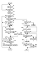
- FIG. 4 is a flowchart illustrating a forced downshift control process in the EV mode according to the first embodiment.
- step S1 the HEV mode is selected.
- step S2 it is determined whether or not mode transition from the HEV mode to the EV mode is permitted. If permitted, the process proceeds to step S3. Otherwise, the HEV mode is continued. Specifically, in the mode map of FIG. 3, it is determined whether or not the driving point defined by the vehicle speed VSP and the accelerator opening APO is in the EV (power running / regeneration) region, and is in the EV region and other When the above condition, specifically, the condition that the battery state is equal to or greater than the predetermined value and not the sudden braking state is satisfied, mode transition to the EV mode is permitted.
- step S3 mode transition to the EV mode is performed. Specifically, the clutch CL is released, fuel injection to the engine 1 is stopped, and the vehicle travels with the torque of the electric motor 2.
- step S4 it is determined whether or not the road surface gradient is equal to or greater than a predetermined value x1, and if it is equal to or greater than the predetermined value x1, the process proceeds to step S5.
- This step corresponds to an uphill road judging means, and if it is not less than a predetermined value x1, it is judged as an uphill road.
- the road surface gradient is estimated based on a deviation between an estimated acceleration to be obtained when traveling on a flat road by the torque of the electric motor 2 and an actual acceleration detected by the acceleration sensor 33. As the actual acceleration is smaller than the estimated acceleration and the deviation is larger, a larger value is calculated as the road gradient.
- step S5 it is determined whether or not the vehicle speed VSP is less than the predetermined vehicle speed VSP1, and when it is determined that the vehicle speed VSP is less than the predetermined vehicle speed VSP1, the process proceeds to step S6, and when it is determined that the vehicle speed VSP is equal to or higher than the predetermined vehicle speed VSP1, the process proceeds to step S14.
- the predetermined vehicle speed VSP1 is a value at which it can be determined that the vehicle is stopped, and is a vehicle speed at which a forced downshift can be performed by clutch CL engagement, which will be described later, and the variator CVT can start an uphill road described later.
- the vehicle speed can be downshifted to the gear ratio G1.
- step S6 it is determined whether or not the actual transmission gear ratio G of the variator CVT is higher than the uphill road startable gear ratio G0. If it is high, the process proceeds to step S7, and the uphill road startable gear ratio G0 or lower is lower. In this case, this control flow is finished. Thereby, it is not necessary to perform useless downshift control, and deterioration of fuel consumption due to engine restart or the like can be avoided.
- the uphill road startable transmission ratio G0 is a minimum transmission ratio or a transmission ratio in the vicinity of the minimum transmission ratio that is higher than the minimum transmission ratio and that can climb the strictest uphill conditions. Therefore, when the downshift to the uphill road startable transmission gear ratio G0 is completed, stable start can be performed on all possible uphill roads.
- step S7 the engine 1 is started by the starter motor 3.
- step S8 the variator CVT is forcibly downshifted toward the gear ratio G0 capable of starting on an uphill road.
- the current travel mode is the EV mode
- the gear ratio of the variator CVT is not related to the travel at this time, but the downshift is forcibly executed.
- the engine 1 is started in step S7, and the pulley 1 is controlled by hydraulic control of each pulley while the variator CVT is rotated by the engine 1.
- Downshift At this time, a hydraulic source for hydraulic control can be supplied by a mechanical oil pump O / P.
- step S9 it is determined whether or not hill hold control is necessary. If not necessary, the process proceeds to step S11, and if necessary, the process proceeds to step S10.
- step S10 hill hold control is turned ON.
- the hill hold control means that the brake fluid pressure in the wheel cylinder is sealed until the vehicle is able to start without torque being transmitted to the drive wheels 5 regardless of the driver's brake pedal operation. It restricts movement.
- the wheel cylinder may be pressurized by a brake actuator such as a VDC control unit interposed between the master cylinder and the wheel cylinder, and is not particularly limited.
- step S11 it is determined whether or not the actual transmission gear ratio G of the variator CVT has reached the uphill road startable transmission gear ratio G0. If so, the process proceeds to step S12. If not, the process returns to step S8 to force Continue downshifting.
- step S12 it is determined whether or not the accelerator pedal opening APO is greater than or equal to the predetermined opening APO1, and if it is greater than or equal to the predetermined opening APO1, the process proceeds to step S13, and otherwise, the process repeats step S12 and waits.
- the predetermined opening APO1 is a predetermined value at which it can be determined that there is a driver's start request.
- step S13 the clutch CL is turned on, that is, the engagement is started, and when the hill hold control is performed, the hill hold control is turned off and the vehicle starts.
- step S14 it is determined whether or not the actual gear ratio G of the variator CVT is higher than the uphill road startable gear ratio G1, and if it is high, the process proceeds to step S7, and the uphill road startable gear ratio G1 or lower is lower In this case, this control flow is finished. Thereby, it is not necessary to perform useless downshift control, and deterioration of fuel consumption due to engine restart or the like can be avoided.
- the uphill road startable transmission ratio G1 is the same as the uphill road startable transmission ratio G0, which is the minimum transmission ratio or near the lowest transmission ratio that is higher than the minimum transmission ratio and can climb up the most severe uphill conditions. Is the ratio.
- the driving force for the inertia of the vehicle is not required, so it may be set to a gear ratio slightly higher than G0, or set to a gear ratio according to the vehicle speed VSP. Also good.
- the downshift to the uphill road startable gear ratio G1 is completed, stable reacceleration with an appropriate gear ratio is possible on any uphill road that can be assumed.
- step S15 the clutch CL is turned ON.
- step S16 the variator CVT is forcibly downshifted toward the gear ratio G1 capable of starting on an uphill road.
- the current travel mode is the EV mode
- the gear ratio of the variator CVT is not related to the travel at this time, but the downshift is forcibly executed.
- the clutch CL is engaged in step S15, and the hydraulic control of each pulley is performed while rotating the variator CVT by the drive wheel 5.
- the hydraulic source for the hydraulic control may be a mechanical oil pump O / P or may be supplied by an electric oil pump EO / P as necessary.
- step S17 it is determined whether or not the actual transmission gear ratio G of the variator CVT has reached the uphill road startable transmission gear ratio G1, and if so, the process proceeds to step S18, and if not, the process returns to step S19 to force Continue downshifting.
- step S18 it is determined whether or not the accelerator pedal opening APO is equal to or larger than the predetermined opening APO1, and if it is equal to or larger than the predetermined opening APO1, the process proceeds to step S20. Otherwise, the process proceeds to step S19.
- step S19 the clutch CL is turned off and the process returns to step S18. This is because, in particular, when a reacceleration intention or the like is not detected, the friction loss caused by bringing the variator CVT by avoiding the clutch CL is avoided, and the process waits until the reacceleration intention is detected.
- step S20 the engine 1 is started. That is, when the intention of reacceleration is detected while traveling in the EV mode on the uphill road, the torque of only the electric motor 2 is insufficient, so the engine driving force is ensured by starting the engine 1. .
- step S21 it is determined whether or not the clutch CL is in an ON state. When the clutch CL is in an ON state, that is, when the clutch CL is engaged, the present control flow is terminated. Then re-accelerate.
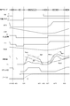
- FIG. 5 is a time chart showing the forced downshift action by the engine of the first embodiment.
- BS represents the ON / OFF state of the brake switch 26
- the gradient flag represents the judgment state by the uphill road judgment in step S4 (ON if the uphill road, OFF otherwise)
- Tm is the motor of the electric motor 2
- the torque represents the torque
- Ne represents the engine rotational speed
- Nmot represents the motor rotational speed of the electric motor 2
- Nout represents the drive wheel rotational speed
- Npri represents the primary pulley rotational speed
- Nsec represents the secondary pulley rotational speed.
- the initial running state is a state in which the accelerator pedal is started to be released in the HEV mode.
- the gradient flag is turned on and the engine 1 is started.
- the uphill road startable gear ratio G0 is set as the target gear ratio, and the primary pulley rotation speed Npri and the secondary pulley rotation speed Nsec increase as the engine speed increases, and the gear ratio G also starts uphill road start.
- the gear shift is started toward the possible gear ratio G0.
- the hill hold request is turned on, and the reverse of the vehicle is suppressed. The hill hold control is continued until the accelerator pedal is depressed and the vehicle can start.
- FIG. 6 is a time chart showing the forced downshift action by the clutch of the first embodiment.
- the initial driving state is a state in which the accelerator pedal is started to be released in the HEV mode.
- APO becomes zero
- the motor torque Tm also becomes zero
- the reduction of the vehicle speed VSP is started.
- the motor rotation speed Nmot also starts to decrease.
- the clutch CL is released as preparation for performing regenerative braking.
- mode transition permission from the HEV mode to the EV mode is permitted at time t13, the fuel injection of the engine 1 is stopped and the motor torque Tm generates regenerative torque.
- the clutch CL is released because the EV mode is currently selected.
- the engine speed Ne, the primary pulley speed Npri, and the secondary pulley speed Nsec all decrease.
- the coasting state is established when the brake pedal is released along with the change from the brake pedal to the accelerator pedal.
- the accelerator pedal is depressed at time t17, engine 1 is started.
- Engine 1 variator CVT (continuously variable transmission 4) coupled to the output shaft of engine 1, a clutch coupled to the output shaft of variator CVT, and drive wheels 5 coupled to the output shaft of the clutch
- a hybrid controller that controls the electric motor 2 coupled to the drive wheels 5, the outputs of the engine 1 and the electric motor 2, the engagement and disengagement of the clutch, and the gear ratio of the continuously variable transmission 4 according to the operating state 21 (control means) includes a step S4 (uphill road determination means) for determining whether or not the vehicle is on an uphill road, and the hybrid controller 21 releases the clutch CL.
- the engine 1 When it is determined that the vehicle is on an uphill road in the EV mode (electric vehicle mode) in which the engine 1 is stopped and can be driven by the driving force of the electric motor 2, the engine 1 is started and the variator CVT is started.
- the A control device for a hybrid vehicle forcibly downshifting to a predetermined uphill road startable gear ratio G0. Therefore, even when the vehicle is on the uphill road in EV mode, even if the HEV mode is switched using the engine 1, the gear ratio of the variator CVT is downshifted to the uphill road startable gear ratio G0.
- the driving force of the engine 1 can be sufficiently transmitted to the driving wheels, and the vehicle can travel stably.
- the hybrid controller 21 determines that the vehicle is on an uphill road while traveling in the EV mode, the hybrid controller 21 engages the clutch CL and downshifts the variator CVT to a predetermined uphill road startable transmission ratio G1.
- the gear ratio of the variator CVT can be started on the uphill road. Since it is downshifted to G0, the driving force of the engine 1 can be sufficiently transmitted to the driving wheels, and the vehicle can travel stably.
- the vehicle controller characterized in that the hybrid controller 21 prohibits a forced downshift when the speed change ratio of the variator CVT is lower than the speed change ratio Go or G1 capable of starting on an uphill road. Thereby, it is not necessary to perform useless downshift control, and deterioration of fuel consumption due to engine restart or the like can be avoided.
- the negative region on the vertical axis is determined based on ON or OFF of the brake switch 26.
- the present invention is not limited to this, and the stroke sensor of the brake pedal 16 is not limited thereto. May be determined based on the output value of the brake fluid pressure sensor, or based on the output value of a brake fluid pressure sensor that detects the master cylinder pressure or the like.
Landscapes
- Engineering & Computer Science (AREA)
- Chemical & Material Sciences (AREA)
- Combustion & Propulsion (AREA)
- Transportation (AREA)
- Mechanical Engineering (AREA)
- Automation & Control Theory (AREA)
- Hybrid Electric Vehicles (AREA)
- Control Of Transmission Device (AREA)
- Electric Propulsion And Braking For Vehicles (AREA)
Abstract
Description
2 電動モータ(動力源)
3 スタータモータ
4 Vベルト式無段変速機
5 駆動輪
6 プライマリプーリ
7 セカンダリプーリ
8 Vベルト
CVT バリエータ(無段変速機構)
T/C トルクコンバータ
9,11 ファイナルギヤ組
12 バッテリ
13 インバータ
14 ブレーキディスク
15 キャリパ
16 ブレーキペダル
19 アクセルペダル
21 ハイブリッドコントローラ
22 エンジンコントローラ
23 モータコントローラ
24 変速機コントローラ
25 バッテリコントローラ
26 ブレーキスイッチ
27 アクセルペダル開度センサ
O/P オイルポンプ
31 副変速機
CL クラッチ
H/C ハイクラッチ
R/B リバースブレーキ
L/B ローブレーキ
32 車速センサ
図1は、実施例1のハイブリッド車両の駆動系およびその全体制御システムを示す概略系統図である。図1のハイブリッド車両は、エンジン1および電動モータ2を動力源として搭載され、エンジン1は、スタータモータ3により始動する。エンジン1は、Vベルト式の無段変速機4を介して駆動輪5に適宜切り離し可能に駆動結合する。
インバータ13は、バッテリ12の直流電力を交流電力に変換して電動モータ2へ供給すると共に、電動モータ2への供給電力を加減することにより、電動モータ2を駆動力制御および回転方向制御する。
なお電動モータ2は、上記のモータ駆動のほかに発電機としても機能し、回生制動の用にも供する。この回生制動時はインバータ13が、電動モータ2に回生制動力分の発電負荷をかけることにより、電動モータ2を発電機として作用させ、電動モータ2の発電電力をバッテリ12に蓄電する。
アウタピニオン31poutはリングギヤ31rの内周に噛合させ、キャリア31cを出力回転メンバとして作用するようファイナルギヤ組9に結合する。
キャリア31cとリングギヤ31rとをクラッチCLであるハイクラッチH/Cにより適宜結合可能となし、リングギヤ31rをクラッチCLであるリバースブレーキR/Bにより適宜固定可能となし、サンギヤ31s-2をクラッチCLであるローブレーキL/Bにより適宜固定可能となす。
セカンダリプーリ圧ソレノイド37-2は、変速機コントローラ24からのクランプ力指令に応じてライン圧PLをセカンダリプーリ圧に調圧し、これをセカンダリプーリ7に供給することにより、セカンダリプーリ7がVベルト8をスリップしないよう挟圧する。
ローブレーキ圧ソレノイド38は、変速機コントローラ24が副変速機31の第1速選択指令を発しているとき、ライン圧PLをローブレーキ圧としてローブレーキL/Bに供給することによりこれを締結させ、第1速選択指令を実現する。
ハイクラッチ圧&リバースブレーキ圧ソレノイド39は、変速機コントローラ24が副変速機31の第2速選択指令または後退選択指令を発しているとき、ライン圧PLをハイクラッチ圧&リバースブレーキ圧としてスイッチバルブ41に供給する。
実施例1の電動式オイルポンプEO/Pの最大吐出能力は、機械式オイルポンプO/Pに比べて小さく設定されており、電動式オイルポンプEO/Pのモータ及びポンプの小型化を図っている。
後退選択指令時はスイッチバルブ41が、ソレノイド39からのライン圧PLをリバースブレーキ圧としてリバースブレーキR/Bに向かわせ、これを締結することで副変速機31の後退選択指令を実現する。
次に変速制御処理について説明する。変速機コントローラ24は、予め設定された変速マップを参照しながら、車両の運転状態(実施例1では車速VSP、プライマリ回転速度Npri、アクセルペダル開度APO)に応じて、無段変速機4を制御する。この変速マップでは、従来のベルト式無段変速機の変速マップと同様に、アクセルペダル開度APO毎に変速線が設定されており、無段変速機4の変速はアクセルペダル開度APOに応じて選択される変速線に従って行われる。この変速マップ上には副変速機31の変速を行うモード切換変速線が設定される。そして、無段変速機4の動作点がモード切換変速線を横切った場合、変速機コントローラ24はバリエータCVTと副変速機31の両方で協調変速を行い、高速モード-低速モード間の切換えを行う。
図3は実施例1のハイブリッド車両の走行モードが設定されたモードマップである。図3のモードマップでは、縦軸の0より上はアクセルペダル開度に応じて設定され、0より下についてはブレーキスイッチ26のオン・オフ状態に応じて設定されている。アクセルペダル19が踏み込まれたEV力行領域にあっては、力行車速VSPXまでEVモードによる力行領域が設定されている。また、アクセルペダル19がほとんど踏み込まれていない状態(例えば、1/8よりも十分に小さなアクセルペダル開度)を表す領域には、力行車速VSPXよりも更に高車速の所定車速VSP1までEVモードによる力行領域が設定されている。この所定車速VSP1以下の領域はアクセルペダル19が踏み込まれた状態ではほとんど選択されることはない。
一方、HEVモードによる走行中にアクセルペダル19を解放してコースティング(惰性)走行へ移行した場合や、HEVモードによる力行状態からブレーキペダル16を踏み込んで車両を制動する場合、電動モータ2による回生制動によって車両の運動エネルギーを電力に変換し、これをバッテリ12に蓄電しておくことでエネルギー効率の向上を図る(HEV回生状態)。また、制動トルクが所定値b1より大きな制動トルクとなったときには、電動モータ2のみによる回生制動では制動力が不足すると判断してHEV回生制動状態とする。これにより、摩擦ブレーキも併用し、制動トルクを確保する。また、制動トルクが所定値b1未満であっても、車速が所定車速Vc以下のときには、EV回生状態から摩擦ブレーキによる制動に切り替える。電動モータ2が低回転状態で高い回生トルクを発生させることは望ましくないからである。
次に、HEVモードからEVモードに遷移したときの変速制御に伴う課題について説明する。EVモード中に無段変速機の変速比制御を一切行わない場合、EVモード中の変速比は、EVモードへ切り替わる直前のHEVモード時の変速比となる。よって、EVモードへ切り替わる直前のHEVモード中の変速比がHigh側の変速比であった場合、EVモード中の変速比もHigh側となるため、この状態で車両停止すると、停車中の変速比もHigh側の変速比となっている。このとき、再発進要求に基づいてHEVモードによる発進を行うと、変速比がHigh側にあるため、エンジントルクが変速機により減少して駆動輪に伝達されるため、運転者の要求駆動力を満たすことができないという問題がある。特に車両が登坂路で停車しているときに発進しようとする場合、登坂勾配が急で、かつ、変速比が最High側付近にあるようなときは、駆動輪5に伝達される駆動力が走行抵抗を下回ってしまい、登坂路発進ができなくなるという問題があった。
そこで、実施例1では、EVモードにより走行しているときに、車両が登坂路にあると判定されたときは、エンジンを始動して無段変速機を所定の登坂路発進可能変速比へ強制ダウンシフトすることとした。
図4は実施例1のEVモード時における強制ダウンシフト制御処理を表すフローチャートである。
ステップS1では、HEVモードを選択する。
ステップS2では、HEVモードからEVモードへのモード遷移が許可されているか否かを判断し、許可されているときはステップS3へ進み、それ以外はHEVモードを継続する。具体的には、図3のモードマップにおいて車速VSPとアクセル開度APOとによって規定される運転点がEV(力行・回生)領域にあるか否かを判断し、EV領域にあり、かつ、他の条件、具体的にはバッテリ状態が所定以上であり、急制動状態ではないといった条件を満たしているときは、EVモードへのモード遷移が許可される。
ステップS3では、EVモードへのモード遷移を行う。具体的には、クラッチCLを解放し、エンジン1への燃料噴射を停止し、電動モータ2のトルクによって走行する。
ステップS5では、車速VSPが所定車速VSP1未満か否かを判断し、所定車速VSP1未満と判断されたときはステップS6へ進み、所定車速VSP1以上と判断されたときはステップS14に進む。ここで、所定車速VSP1とは、車両が停止していると判定可能な値であり、かつ、後述するクラッチCL締結による強制ダウンシフトが可能な車速であり、バリエータCVTが後述する登坂路発進可能変速比G1までダウンシフト可能な車速である。
ステップS8では、バリエータCVTを登坂路発進可能変速比G0に向けて強制ダウンシフトを実行する。言い換えると、現在の走行モードがEVモードであり、現時点でバリエータCVTの変速比は走行に関与しないものの、強制的にダウンシフトを実行するものである。尚、バリエータCVTが変速するにはプライマリプーリ6やセカンダリプーリ7が回転している必要があるため、ステップS7においてエンジン1を始動し、エンジン1によりバリエータCVTを回転させつつ各プーリの油圧制御によりダウンシフトを行う。尚、このときの油圧制御の油圧源としては機械式オイルポンプO/Pにより供給可能である。
ステップS9では、ヒルホールド制御が不要か否かを判断し、不要な場合はステップS11に進み、必要な場合はステップS10に進む。
ステップS10では、ヒルホールド制御をONとする。ヒルホールド制御とは、運転者のブレーキペダル操作に係らず駆動輪5にトルクが伝達されて車両が発進可能となるまでの間、ホイルシリンダ内のブレーキ液圧を封入し、登坂路における車両の移動を規制するものである。尚、ホイルシリンダ内の油圧が不足する場合は、マスタシリンダとホイルシリンダとの間に介在されたVDC制御ユニット等のブレーキアクチュエータによってホイルシリンダを加圧してもよく、特に限定しない。
ステップS12では、アクセルペダル開度APOが所定開度APO1以上か否かを判断し、所定開度APO1以上のときはステップS13に進み、それ以外のときは本ステップS12を繰り返して待機する。ここで、所定開度APO1とは、運転者の発進要求があると判断できる所定値である。尚、既にエンジン1は始動した状態であることから、登坂路と判定された車両停止時にあっては、いつでもエンジン1の駆動力を用いた発進が可能な状態としておく。これにより、登坂路での発進性能を確保できる。
ステップS13では、クラッチCLをON、すなわち締結を開始し、ヒルホールド制御が行われている場合には、ヒルホールド制御をOFFして発進する。
ステップS14では、バリエータCVTの実変速比Gが登坂路発進可能変速比G1よりHigh側か否かを判断し、High側のときはステップS7に進み、登坂路発進可能変速比G1以下のLow側のときには本制御フローを終了する。これにより、無駄なダウンシフト制御を行う必要が無く、エンジン再始動等に伴う燃費悪化を回避できる。ここで、登坂路発進可能変速比G1とは、登坂路発進可能変速比G0と同様に最低変速比もしくは最低変速比よりHigh側であって最も厳しい登坂条件を登坂可能な最低変速比付近の変速比である。ただし、走行中であるため、車両の慣性分の駆動力が必要とされないことから、G0よりも若干High側の変速比に設定してもよいし、車速VSPに応じた変速比に設定してもよい。これにより、登坂路発進可能変速比G1へのダウンシフトが完了すると、想定されうるあらゆる登坂路において適正な変速比による安定した再加速が可能になる。
ステップS16では、バリエータCVTを登坂路発進可能変速比G1に向けて強制ダウンシフトを実行する。言い換えると、現在の走行モードがEVモードであり、現時点でバリエータCVTの変速比は走行に関与しないものの、強制的にダウンシフトを実行するものである。尚、バリエータCVTが変速するにはプライマリプーリ6やセカンダリプーリ7が回転している必要があるため、ステップS15においてクラッチCLを締結し、駆動輪5によりバリエータCVTを回転させつつ各プーリの油圧制御によりダウンシフトを行う。尚、このときの油圧制御の油圧源としては機械式オイルポンプO/Pでもよいし、必要に応じて電動式オイルポンプEO/Pにより供給してもよい。
ステップS18では、アクセルペダル開度APOが所定開度APO1以上か否かを判断し、所定開度APO1以上のときはステップS20に進み、それ以外のときは本ステップS19に進む。
ステップS20では、エンジン1を始動する。すなわち、登坂路においてEVモードで走行中に再加速意図が検出された場合には、電動モータ2のみのトルクでは不足することから、エンジン1を始動することでエンジン駆動力を確保するためである。
ステップS21では、クラッチCLをON状態か否かを判断し、ON状態、すなわち締結しているときにはそのまま本制御フローを終了し、解放しているときにはステップS22に進んでクラッチCLをON、すなわち締結して再加速を行う。
次に、上記EVモード時における強制ダウンシフト制御処理に基づく作用について説明する。図5は実施例1のエンジンによる強制ダウンシフト作用を表すタイムチャートである。尚、BSはブレーキスイッチ26のON・OFF状態を表し、勾配フラグはステップS4の登坂路判定による判定状態(登坂路であればON、それ以外はOFF)を表し、Tmは電動モータ2のモータトルクを表し、Neはエンジン回転数、Nmotは電動モータ2のモータ回転数、Noutは駆動輪回転数、Npriはプライマリプーリ回転数、Nsecはセカンダリプーリ回転数を表す。また、初期の走行状態はHEVモードでアクセルペダルを離し始めている状態である。
時刻t2において、ブレーキペダルが踏み込まれると、回生制動を行うための準備としてクラッチCLを解放する。
時刻t3において、HEVモードからEVモードへのモード遷移許可がなされると、エンジン1の燃料噴射を停止すると共に、モータトルクTmは回生トルクを発生する。尚、電動モータ2による回生制動が所定車速Vcまで行われると、それ以後の低車速領域では摩擦ブレーキによる制動に切り替えられるため、回生トルクは0となる。
時刻t5において、ブレーキペダルからアクセルペダルへの踏み替えに伴い、ブレーキペダルがOFFとされると、ヒルホールド要求がONとされ、車両の後退が抑制される。そして、アクセルペダルが踏み込まれて発進可能な状態となるまでは、ヒルホールド制御が継続される。
時刻t7において、クラッチCLの締結が完了したと判断されると、エンジントルク及びモータトルクが共に出力され、車両が発進する。このとき、バリエータCVTが登坂路発進可能変速比G0に変速されているため、エンジントルクを十分に活用した発進が可能となり、登坂路であってもスムーズに発進できる。
時刻t11において、アクセルペダルが完全に解放されるとAPOがゼロとなり、モータトルクTmもゼロとなって車速VSPの減少を開始する。これに伴い、モータ回転数Nmotも低下し始める。
時刻t12において、ブレーキペダルが踏み込まれると、回生制動を行うための準備としてクラッチCLを解放する。
時刻t13において、HEVモードからEVモードへのモード遷移許可がなされると、エンジン1の燃料噴射を停止すると共に、モータトルクTmは回生トルクを発生する。
時刻t16において、運転者が減速意図から加速意図に変更(チェンジマインド)されると、ブレーキペダルからアクセルペダルへの踏み替えに伴い、ブレーキペダルが解放されるとコースト走行状態となる。
時刻t17において、アクセルペダルが踏み込まれると、エンジン1が始動される。これにより、エンジン回転数Neが立ち上がり、トルクコンバータT/Cを介してプライマリプーリ回転数Npri及びセカンダリプーリ回転数Nsecが立ち上がり、エンジントルク及びモータトルクが共に出力される。まだクラッチCLは締結していないため、エンジントルクは駆動輪5に伝達されず、モータトルクのみによって車両は緩やかに加速を開始する。
時刻t171において、クラッチCLの締結が開始されると、エンジントルクが駆動輪5に伝達され、更に車両が加速する。このとき、バリエータCVTが登坂路発進可能変速比G1に変速されているため、エンジントルクを十分に活用した再加速が可能となり、登坂路であってもスムーズに加速できる。
時刻t18において、クラッチCLの締結が完了すると、登坂路発進可能変速比G1によって通常のHEVモードによる走行が行われる。
(1)エンジン1と、エンジン1の出力軸に結合されたバリエータCVT(無段変速機4)と、バリエータCVTの出力軸に結合されたクラッチと、クラッチの出力軸に結合された駆動輪5と、駆動輪5に結合された電動モータ2と、運転状態に応じてエンジン1及び電動モータ2の出力と、クラッチの締結及び解放と、無段変速機4の変速比とを制御するハイブリッドコントローラ21(制御手段)と、を備えたハイブリッド車両の制御装置において、車両が登坂路にあるか否かを判定するステップS4(登坂路判定手段)を備え、ハイブリッドコントローラ21は、クラッチCLを解放し、エンジン1を停止して、電動モータ2の駆動力により走行可能なEVモード(電気自動車モード)のときに、車両が登坂路にあると判定されたときは、エンジン1を始動してバリエータCVTを所定の登坂路発進可能変速比G0へ強制ダウンシフトすることを特徴とするハイブリッド車両の制御装置。
よって、EVモードで登坂路にあるときに、エンジン1を使用して走行するHEVモードに切り替えられたとしても、バリエータCVTの変速比が登坂路発進可能変速比G0にダウンシフトされているため、エンジン1の駆動力を十分に駆動輪に伝達することが可能となり、安定して走行することができる。
よって、エンジン1を再始動することなくバリエータCVTを登坂路発進可能変速比G1にダウンシフトすることが可能となり、燃費を向上できる。また、EVモードで登坂路を走行中に、チェンジマインドによって再加速要求がなされ、エンジン1を使用して走行するHEVモードに切り替えられたとしても、バリエータCVTの変速比が登坂路発進可能変速比G0にダウンシフトされているため、エンジン1の駆動力を十分に駆動輪に伝達することが可能となり、安定して走行することができる。
すなわち、運転者の発進要求があったからといって強制ダウンシフト中にクラッチCLを締結してしまうと、バリエータCVTが登坂路発進可能変速比G0よりもHigh側にある状態で発進することとなり、発進できないおそれがある。そこで、強制ダウンシフトを優先することで、強制ダウンシフト中におけるクラッチ締結に伴う発進性の悪化を回避できる。
これにより、無駄なダウンシフト制御を行う必要が無く、エンジン再始動等に伴う燃費悪化を回避できる。
以上、本願発明を各実施例に基づいて説明したが、上記構成に限られず、他の構成であっても本願発明に含まれる。実施例ではスタータモータ3によりエンジン再始動を行う構成を示したが、他の構成であっても構わない。具体的には、近年、アイドリングストップ機能付き車両であって、オルタネータをモータ・ジェネレータに置き換え、このモータ・ジェネレータにオルタネータ機能を加えてエンジン始動機能を付加することにより、アイドリングストップからのエンジン再始動時に、スタータモータではなく、このモータ・ジェネレータによりエンジン再始動を行う技術が実用化されている。本願発明も上記のようなモータ・ジェネレータによりエンジン再始動を行う構成としてもよい。
Claims (4)
- エンジンと、
前記エンジンの出力軸に結合された無段変速機と、
前記無段変速機の出力軸に結合されたクラッチと、
前記クラッチの出力軸に結合された駆動輪と、
前記駆動輪に結合されたモータと、
運転状態に応じて前記エンジン及び前記モータの出力と、前記クラッチの締結及び解放と、前記無段変速機の変速比とを制御する制御手段と、
を備えたハイブリッド車両の制御装置において、
車両が登坂路にあるか否かを判定する登坂路判定手段を備え、
前記制御手段は、前記クラッチを解放し、前記エンジンを停止して、前記モータの駆動力により走行可能な電気自動車モードのときに、車両が登坂路にあると判定されたときは、前記エンジンを始動して前記無段変速機を所定の登坂路発進可能変速比へ強制ダウンシフトすることを特徴とするハイブリッド車両の制御装置。 - 請求項1に記載のハイブリッド車両の制御装置において、
前記制御手段は、前記電気自動車モードによる走行中に、車両が登坂路にあると判定されたときは、前記クラッチを締結して前記無段変速機を所定の登坂路発進可能変速比へダウンシフトすることを特徴とするハイブリッド車両の制御装置。 - 請求項1に記載のハイブリッド車両の制御装置において、
前記制御手段は、前記強制ダウンシフト中に運転者が発進を要求したときは、前記強制ダウンシフトの完了後、前記クラッチを締結して発進することを特徴とする車両の制御装置。 - 請求項1ないし3いずれか一つに記載のハイブリッド車両の制御装置において、
前記制御手段は、前記無段変速機の変速比が前記所定の登坂路発進可能変速比よりもロー側のときは前記強制ダウンシフトを禁止することを特徴とする車両の制御装置。
Priority Applications (4)
| Application Number | Priority Date | Filing Date | Title |
|---|---|---|---|
| JP2016508570A JP6115978B2 (ja) | 2014-03-20 | 2015-01-28 | ハイブリッド車両の制御装置 |
| US15/121,797 US9758158B2 (en) | 2014-03-20 | 2015-01-28 | Hybrid vehicle control device |
| CN201580015258.1A CN106103224B (zh) | 2014-03-20 | 2015-01-28 | 混合动力车辆的控制装置 |
| EP15764587.0A EP3121081B1 (en) | 2014-03-20 | 2015-01-28 | Hybrid vehicle controller |
Applications Claiming Priority (2)
| Application Number | Priority Date | Filing Date | Title |
|---|---|---|---|
| JP2014057584 | 2014-03-20 | ||
| JP2014-057584 | 2014-03-20 |
Publications (1)
| Publication Number | Publication Date |
|---|---|
| WO2015141285A1 true WO2015141285A1 (ja) | 2015-09-24 |
Family
ID=54144265
Family Applications (1)
| Application Number | Title | Priority Date | Filing Date |
|---|---|---|---|
| PCT/JP2015/052329 Ceased WO2015141285A1 (ja) | 2014-03-20 | 2015-01-28 | ハイブリッド車両の制御装置 |
Country Status (5)
| Country | Link |
|---|---|
| US (1) | US9758158B2 (ja) |
| EP (1) | EP3121081B1 (ja) |
| JP (1) | JP6115978B2 (ja) |
| CN (1) | CN106103224B (ja) |
| WO (1) | WO2015141285A1 (ja) |
Cited By (2)
| Publication number | Priority date | Publication date | Assignee | Title |
|---|---|---|---|---|
| JP2018016130A (ja) * | 2016-07-26 | 2018-02-01 | 三菱自動車工業株式会社 | ハイブリッド車両用ギア制御装置 |
| KR101836669B1 (ko) | 2016-07-14 | 2018-03-09 | 현대자동차주식회사 | 하이브리드 차량용 변속 제어방법 |
Families Citing this family (8)
| Publication number | Priority date | Publication date | Assignee | Title |
|---|---|---|---|---|
| US9937916B2 (en) * | 2015-07-21 | 2018-04-10 | Ford Global Technologies, Llc | Methods and system for reducing transmission shifting |
| US10948081B2 (en) * | 2017-03-02 | 2021-03-16 | Toyota Motor Engineering & Manufacturing North America, Inc. | Downsized CVT oil pump achieved by slip device |
| KR101876740B1 (ko) * | 2017-04-17 | 2018-07-10 | 현대자동차주식회사 | 하이브리드 자동차 및 그를 모드 전환 방법 |
| KR102610753B1 (ko) * | 2018-12-11 | 2023-12-08 | 현대자동차주식회사 | 하이브리드 차량 제어 장치, 그를 포함한 시스템 및 그 방법 |
| CN113858965B (zh) * | 2020-06-30 | 2023-09-08 | 广州汽车集团股份有限公司 | 电动汽车变速器降档控制方法和系统 |
| CN111806422B (zh) * | 2020-07-28 | 2022-06-07 | 盛瑞传动股份有限公司 | 一种混合动力变速器坡道起步控制方法 |
| JP7650658B2 (ja) * | 2020-12-28 | 2025-03-25 | 株式会社シマノ | 人力駆動車用の制御装置 |
| CN112918461A (zh) * | 2021-03-24 | 2021-06-08 | 吉林大学 | 一种并联式混合动力汽车动力域控制系统 |
Citations (4)
| Publication number | Priority date | Publication date | Assignee | Title |
|---|---|---|---|---|
| JPH11178113A (ja) * | 1997-12-12 | 1999-07-02 | Toyota Motor Corp | ハイブリッド車の駆動制御装置 |
| JP2006248371A (ja) * | 2005-03-10 | 2006-09-21 | Fujitsu Ten Ltd | 車両制御装置、無段変速機制御装置及びその制御方法 |
| JP2007001392A (ja) * | 2005-06-22 | 2007-01-11 | Toyota Motor Corp | 車両用駆動装置の制御装置 |
| JP2013086649A (ja) * | 2011-10-18 | 2013-05-13 | Jatco Ltd | ハイブリッド車両の制御装置 |
Family Cites Families (7)
| Publication number | Priority date | Publication date | Assignee | Title |
|---|---|---|---|---|
| JP3803205B2 (ja) * | 1998-12-28 | 2006-08-02 | 本田技研工業株式会社 | ハイブリッド自動車 |
| JP2005113967A (ja) * | 2003-10-03 | 2005-04-28 | Toyota Motor Corp | 車両用自動変速機の変速制御装置 |
| JP4297127B2 (ja) * | 2006-04-05 | 2009-07-15 | トヨタ自動車株式会社 | 車両およびその制御方法 |
| US8109852B2 (en) * | 2006-06-08 | 2012-02-07 | Vmt Technologies Llc | Variable speed transmission with rotating and orbiting drive gears |
| DE102010003673A1 (de) * | 2010-04-07 | 2011-10-13 | Robert Bosch Gmbh | Verfahren zum Betreiben eines Fahrzeugs |
| AU2011318926B2 (en) * | 2010-10-22 | 2015-12-17 | Hino Motors, Ltd. | Vehicle, control method, and program |
| JP2015134508A (ja) | 2012-03-26 | 2015-07-27 | ジヤトコ株式会社 | ハイブリッド車両の電気走行減速時変速制御装置 |
-
2015
- 2015-01-28 EP EP15764587.0A patent/EP3121081B1/en active Active
- 2015-01-28 WO PCT/JP2015/052329 patent/WO2015141285A1/ja not_active Ceased
- 2015-01-28 CN CN201580015258.1A patent/CN106103224B/zh active Active
- 2015-01-28 JP JP2016508570A patent/JP6115978B2/ja active Active
- 2015-01-28 US US15/121,797 patent/US9758158B2/en active Active
Patent Citations (4)
| Publication number | Priority date | Publication date | Assignee | Title |
|---|---|---|---|---|
| JPH11178113A (ja) * | 1997-12-12 | 1999-07-02 | Toyota Motor Corp | ハイブリッド車の駆動制御装置 |
| JP2006248371A (ja) * | 2005-03-10 | 2006-09-21 | Fujitsu Ten Ltd | 車両制御装置、無段変速機制御装置及びその制御方法 |
| JP2007001392A (ja) * | 2005-06-22 | 2007-01-11 | Toyota Motor Corp | 車両用駆動装置の制御装置 |
| JP2013086649A (ja) * | 2011-10-18 | 2013-05-13 | Jatco Ltd | ハイブリッド車両の制御装置 |
Non-Patent Citations (1)
| Title |
|---|
| See also references of EP3121081A4 * |
Cited By (3)
| Publication number | Priority date | Publication date | Assignee | Title |
|---|---|---|---|---|
| KR101836669B1 (ko) | 2016-07-14 | 2018-03-09 | 현대자동차주식회사 | 하이브리드 차량용 변속 제어방법 |
| US10071726B2 (en) | 2016-07-14 | 2018-09-11 | Hyundai Motor Company | Shifting control method for hybrid vehicles |
| JP2018016130A (ja) * | 2016-07-26 | 2018-02-01 | 三菱自動車工業株式会社 | ハイブリッド車両用ギア制御装置 |
Also Published As
| Publication number | Publication date |
|---|---|
| JPWO2015141285A1 (ja) | 2017-04-06 |
| US20170015301A1 (en) | 2017-01-19 |
| EP3121081B1 (en) | 2018-08-22 |
| EP3121081A4 (en) | 2017-08-02 |
| EP3121081A1 (en) | 2017-01-25 |
| CN106103224A (zh) | 2016-11-09 |
| CN106103224B (zh) | 2018-03-30 |
| US9758158B2 (en) | 2017-09-12 |
| JP6115978B2 (ja) | 2017-04-19 |
Similar Documents
| Publication | Publication Date | Title |
|---|---|---|
| JP6113910B2 (ja) | ハイブリッド車両の制御装置 | |
| JP6115978B2 (ja) | ハイブリッド車両の制御装置 | |
| CN105050844B (zh) | 混合动力车辆 | |
| CN104797475B (zh) | 混合动力车辆的控制装置 | |
| JP6052775B2 (ja) | ハイブリッド車両の制御装置 | |
| JP6569095B2 (ja) | ハイブリッド車両の制御装置 | |
| JP2015134508A (ja) | ハイブリッド車両の電気走行減速時変速制御装置 | |
| JP6340605B2 (ja) | ハイブリッド車両の制御装置 | |
| JP2014234133A (ja) | ハイブリッド車両の制御装置 | |
| JPWO2014065302A1 (ja) | ハイブリッド車両のモード切り替え制御装置 | |
| JP6303783B2 (ja) | ハイブリッド車両の制御装置 | |
| JP6113478B2 (ja) | ハイブリッド車両の制御装置 | |
| JP6330190B2 (ja) | ハイブリッド車両の制御装置 | |
| CN108025739A (zh) | 车辆的控制装置及车辆的控制方法 | |
| JP6273505B2 (ja) | ハイブリッド車両の制御装置 | |
| JP2014113902A (ja) | ハイブリッド車両のモード切り替え制御装置 | |
| WO2014091838A1 (ja) | ハイブリッド車両の制御装置 | |
| JP2014091438A (ja) | ハイブリッド車両の変速制御装置 | |
| JP2015143050A (ja) | ハイブリッド車両の制御装置 | |
| JP6330189B2 (ja) | ハイブリッド車両の制御装置 |
Legal Events
| Date | Code | Title | Description |
|---|---|---|---|
| 121 | Ep: the epo has been informed by wipo that ep was designated in this application |
Ref document number: 15764587 Country of ref document: EP Kind code of ref document: A1 |
|
| ENP | Entry into the national phase |
Ref document number: 2016508570 Country of ref document: JP Kind code of ref document: A |
|
| WWE | Wipo information: entry into national phase |
Ref document number: 15121797 Country of ref document: US |
|
| REEP | Request for entry into the european phase |
Ref document number: 2015764587 Country of ref document: EP |
|
| WWE | Wipo information: entry into national phase |
Ref document number: 2015764587 Country of ref document: EP |
|
| NENP | Non-entry into the national phase |
Ref country code: DE |