WO2015141806A1 - フォイル軸受 - Google Patents
フォイル軸受 Download PDFInfo
- Publication number
- WO2015141806A1 WO2015141806A1 PCT/JP2015/058364 JP2015058364W WO2015141806A1 WO 2015141806 A1 WO2015141806 A1 WO 2015141806A1 JP 2015058364 W JP2015058364 W JP 2015058364W WO 2015141806 A1 WO2015141806 A1 WO 2015141806A1
- Authority
- WO
- WIPO (PCT)
- Prior art keywords
- bearing
- foil
- powder
- bearing surface
- shaft
- Prior art date
- Legal status (The legal status is an assumption and is not a legal conclusion. Google has not performed a legal analysis and makes no representation as to the accuracy of the status listed.)
- Ceased
Links
Images


Classifications
-
- F—MECHANICAL ENGINEERING; LIGHTING; HEATING; WEAPONS; BLASTING
- F16—ENGINEERING ELEMENTS AND UNITS; GENERAL MEASURES FOR PRODUCING AND MAINTAINING EFFECTIVE FUNCTIONING OF MACHINES OR INSTALLATIONS; THERMAL INSULATION IN GENERAL
- F16C—SHAFTS; FLEXIBLE SHAFTS; ELEMENTS OR CRANKSHAFT MECHANISMS; ROTARY BODIES OTHER THAN GEARING ELEMENTS; BEARINGS
- F16C17/00—Sliding-contact bearings for exclusively rotary movement
- F16C17/02—Sliding-contact bearings for exclusively rotary movement for radial load only
- F16C17/024—Sliding-contact bearings for exclusively rotary movement for radial load only with flexible leaves to create hydrodynamic wedge, e.g. radial foil bearings
-
- F—MECHANICAL ENGINEERING; LIGHTING; HEATING; WEAPONS; BLASTING
- F16—ENGINEERING ELEMENTS AND UNITS; GENERAL MEASURES FOR PRODUCING AND MAINTAINING EFFECTIVE FUNCTIONING OF MACHINES OR INSTALLATIONS; THERMAL INSULATION IN GENERAL
- F16C—SHAFTS; FLEXIBLE SHAFTS; ELEMENTS OR CRANKSHAFT MECHANISMS; ROTARY BODIES OTHER THAN GEARING ELEMENTS; BEARINGS
- F16C17/00—Sliding-contact bearings for exclusively rotary movement
- F16C17/04—Sliding-contact bearings for exclusively rotary movement for axial load only
- F16C17/042—Sliding-contact bearings for exclusively rotary movement for axial load only with flexible leaves to create hydrodynamic wedge, e.g. axial foil bearings
-
- F—MECHANICAL ENGINEERING; LIGHTING; HEATING; WEAPONS; BLASTING
- F16—ENGINEERING ELEMENTS AND UNITS; GENERAL MEASURES FOR PRODUCING AND MAINTAINING EFFECTIVE FUNCTIONING OF MACHINES OR INSTALLATIONS; THERMAL INSULATION IN GENERAL
- F16C—SHAFTS; FLEXIBLE SHAFTS; ELEMENTS OR CRANKSHAFT MECHANISMS; ROTARY BODIES OTHER THAN GEARING ELEMENTS; BEARINGS
- F16C33/00—Parts of bearings; Special methods for making bearings or parts thereof
- F16C33/02—Parts of sliding-contact bearings
- F16C33/04—Brasses; Bushes; Linings
- F16C33/06—Sliding surface mainly made of metal
- F16C33/10—Construction relative to lubrication
- F16C33/1005—Construction relative to lubrication with gas, e.g. air, as lubricant
- F16C33/101—Details of the bearing surface, e.g. means to generate pressure such as lobes or wedges
-
- F—MECHANICAL ENGINEERING; LIGHTING; HEATING; WEAPONS; BLASTING
- F16—ENGINEERING ELEMENTS AND UNITS; GENERAL MEASURES FOR PRODUCING AND MAINTAINING EFFECTIVE FUNCTIONING OF MACHINES OR INSTALLATIONS; THERMAL INSULATION IN GENERAL
- F16C—SHAFTS; FLEXIBLE SHAFTS; ELEMENTS OR CRANKSHAFT MECHANISMS; ROTARY BODIES OTHER THAN GEARING ELEMENTS; BEARINGS
- F16C33/00—Parts of bearings; Special methods for making bearings or parts thereof
- F16C33/02—Parts of sliding-contact bearings
- F16C33/04—Brasses; Bushes; Linings
- F16C33/06—Sliding surface mainly made of metal
- F16C33/10—Construction relative to lubrication
- F16C33/1095—Construction relative to lubrication with solids as lubricant, e.g. dry coatings, powder
-
- F—MECHANICAL ENGINEERING; LIGHTING; HEATING; WEAPONS; BLASTING
- F16—ENGINEERING ELEMENTS AND UNITS; GENERAL MEASURES FOR PRODUCING AND MAINTAINING EFFECTIVE FUNCTIONING OF MACHINES OR INSTALLATIONS; THERMAL INSULATION IN GENERAL
- F16C—SHAFTS; FLEXIBLE SHAFTS; ELEMENTS OR CRANKSHAFT MECHANISMS; ROTARY BODIES OTHER THAN GEARING ELEMENTS; BEARINGS
- F16C17/00—Sliding-contact bearings for exclusively rotary movement
- F16C17/12—Sliding-contact bearings for exclusively rotary movement characterised by features not related to the direction of the load
- F16C17/24—Sliding-contact bearings for exclusively rotary movement characterised by features not related to the direction of the load with devices affected by abnormal or undesired positions, e.g. for preventing overheating, for safety
-
- F—MECHANICAL ENGINEERING; LIGHTING; HEATING; WEAPONS; BLASTING
- F16—ENGINEERING ELEMENTS AND UNITS; GENERAL MEASURES FOR PRODUCING AND MAINTAINING EFFECTIVE FUNCTIONING OF MACHINES OR INSTALLATIONS; THERMAL INSULATION IN GENERAL
- F16C—SHAFTS; FLEXIBLE SHAFTS; ELEMENTS OR CRANKSHAFT MECHANISMS; ROTARY BODIES OTHER THAN GEARING ELEMENTS; BEARINGS
- F16C2360/00—Engines or pumps
- F16C2360/23—Gas turbine engines
- F16C2360/24—Turbochargers
Definitions
- the present invention relates to a foil bearing.
- the main shaft of a turbomachine (for example, a gas turbine or turbocharger) rotates at high speed in a high temperature environment.
- a turbomachine for example, a gas turbine or turbocharger
- a foil bearing is known as a bearing that can easily manage the gap width of a bearing gap even in an environment in which a whirl is unlikely to occur and a temperature change is large.
- a bearing surface is constituted by a thin metal plate (foil) having low rigidity with respect to bending, and the load is supported by allowing the bearing surface to bend.
- Patent Document 1 discloses a type of foil bearing that supports a radial load.
- foil bearing of Patent Document 1 when the rotating shaft rotates, an air film is formed in the radial bearing gap between the inner diameter surface of the top foil (bearing foil) constituting the stationary side and the outer peripheral surface of the rotating shaft facing this.
- the rotary shaft is supported in the radial direction by the pressure.
- the top foil and the elastic support part (elastic body) that elastically supports the top foil are elastically deformed according to the operating conditions such as the load acting on the top foil and the ambient temperature.
- the gap width of the bearing gap is automatically adjusted. Therefore, foil bearings are characterized by superior stability compared to general dynamic pressure bearings, and are suitably used as bearings for supporting rotating bodies that rotate at high speeds in high-temperature environments, such as rotors in turbomachinery. obtain.
- the foil bearing since the clearance width of the radial bearing gap is automatically adjusted by elastic deformation of the top foil (bearing surface) itself, it is sufficient to manage the clearance width of the radial bearing gap to about several tens of ⁇ m. . Accordingly, the foil bearing also has an advantage that manufacturing and clearance width management of the bearing clearance can be facilitated as compared with a general dynamic pressure bearing.
- an object of the present invention is to provide a foil bearing capable of further reducing the torque and extending the life.
- the present invention provides a top foil in which either a stationary member or a rotating member is formed of a flexible metal thin plate, and elastically supports the top foil. And an air film is formed in a bearing gap between a first bearing surface provided on the top foil and a second bearing surface of the other member facing the first bearing surface as the rotating side member rotates.
- a powder having lubricity is interposed between the first bearing surface and the second bearing surface, and at least a part of the top foil is air.
- the bearing clearance referred to in the present invention may be a radial bearing clearance or a thrust bearing clearance.
- the present invention can be applied to either a foil bearing that supports a radial load or a foil bearing that supports a thrust load.
- the first bearing surface is Instead of the bearing surface, it can be preferentially brought into contact with a powder having lubricity interposed between both bearing surfaces (hereinafter also referred to as “lubricating powder”).
- lubricating powder a powder having lubricity interposed between both bearing surfaces
- both bearing surfaces are usually in contact with each other, so that a large amount of energy is required after the operation of the bearing starts until it reaches a steady rotation state (fluid lubrication region). Necessary.
- the foil bearing according to the present invention is stopped, the top foil is in the second state in which the holding portion is substantially extinguished, so that the lubricating powder interposed between both bearing surfaces serves as the spacer.
- This function not only reduces the frictional force between the two bearing surfaces, but also makes it easier to draw air between the bearing surfaces by creating a space between the two bearing surfaces. Therefore, after the operation of the bearing is started, a steady rotation state can be quickly realized without requiring large energy. Accordingly, the starting torque can be greatly reduced, and the rotational speed required to support the rotation-side member in a non-contact manner is reduced, so the load on both bearing surfaces is reduced and the durability is improved.
- the lubricating powder interposed between both bearing surfaces is not always held by the holding portion even during steady rotation of the rotating side member, that is, when the top foil is in the first state, and at least a part thereof It is considered that the fluid flows in the bearing gap together with the lubricating fluid (air) or is attached to either one of both bearing surfaces. For this reason, even when the bearing surfaces are in sliding contact with any beat during steady rotation, it is possible to effectively prevent a local temperature rise of the bearing surface and the accompanying deformation and seizure of the bearing surface. Further, when the start and stop of the foil bearing according to the present invention is repeated, sliding contact between the lubricating powder and the bearing surface, pressurization of the lubricating powder by the both bearing surfaces, and the like are repeated.
- the conductive powder adheres and accumulates on either one or both of the bearing surfaces to form a film having excellent lubricity. Thereby, low torque can be realized in all lubrication regions (rotational speed regions). As described above, a foil bearing having a lower torque and a longer life can be realized.
- the lubricating powder can be held and the amount of the lubricating powder supplied to the bearing gap can be limited.
- the low-speed rotation state mixed lubrication area / boundary lubrication area
- the top foil has a function that allows a sufficient amount of lubricating powder to be interposed between both bearing surfaces, the support capacity during steady rotation is reduced. Without inviting the above, it is possible to realize a sufficiently low friction and low torque during low-speed rotation or the like.
- the top foil is formed of a flexible metal thin plate and can be elastically deformed arbitrarily according to the pressure of the air film, for example, the above-described effects can be achieved by simply adjusting the shape of the elastic support portion, for example. It can be enjoyed easily and effectively.
- the lubricating powder for example, an oxide of wear powder generated by wear of at least one of the base material of the top foil and the other member (for example, the shaft) with sliding contact between both bearing surfaces is used. be able to.
- the lubricating powder for example, an oxide of wear powder generated by wear of at least one of the base material of the top foil and the other member (for example, the shaft) with sliding contact between both bearing surfaces.
- At least one of the bearing surfaces is provided with a protrusion protruding toward the other bearing surface.
- the lubricant powder includes a solid lubricant that is different from the wear powder of the top foil and the base material of the other member.
- At least one of the first bearing surface and the second bearing surface is provided on a lubricating coating formed on the base material.
- the contact area between the bearing surfaces can be reduced to achieve a low torque, and a high surface pressure acts on the protrusion during sliding contact between both bearing surfaces. Since minute wear powder is generated quickly, lubricating powder can be quickly interposed between both bearing surfaces. Further, if the configuration of (2) is adopted, since lubricating powder can be interposed between both bearing surfaces from the start of use of the foil bearing, the starting torque and low speed rotation at the start of use of the foil bearing can be achieved. In addition to reducing the rotational torque, the wear of the base material also becomes mild wear, and the oxide of the generated wear powder also functions as a lubricating powder.
- a lubricating powder can be generated by wear of the lubricating coating, so that the starting torque at the start of use of the foil bearing and the rotational torque at the time of low-speed rotation are reduced.
- the wear of the base material also becomes mild wear, and the oxide of the generated wear powder functions as a lubricating powder.
- the foil bearing according to the present invention can be preferably used as a bearing for supporting a rotating side member that rotates at high speed, such as a rotor of a turbomachine (for example, a gas turbine or a turbocharger).
- a turbomachine for example, a gas turbine or a turbocharger
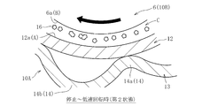
- FIG. 4 is an enlarged view of a main part of FIG. 3, and is a schematic diagram when the top foil is in a second state.
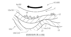
- FIG. 4 is an enlarged view of a main part of FIG. 3, and is a schematic diagram when the top foil is in a first state. It is a principal part enlarged view of the foil bearing which concerns on a modification, Comprising: It is a figure which shows typically the state before the start of use of this foil bearing.
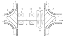
- FIG. 1 conceptually shows a configuration of a gas turbine device called a micro gas turbine as an example of a turbo machine.
- This gas turbine device includes, as a main configuration, a turbine 1 having a blade row, a compressor 2, a generator 3, a combustor 4, and a regenerator 5, and the turbine 1 and the compressor 2 are It is attached to a shaft 6 extending in the horizontal direction and constitutes a rotor on the rotating side together with the shaft 6.
- One axial end of the shaft 6 is connected to the generator 3.
- the combustor 4 mixes fuel with compressed and heated air and burns the fuel to generate high-temperature and high-pressure gas, and the turbine 1 is rotated by the gas.
- the turbine 1 rotates, the rotational force is transmitted to the generator 3 via the shaft 6, and the generator 3 is rotationally driven.
- the electric power generated by rotating the generator 3 is output via the inverter 8. Since the gas after rotating the turbine 1 is at a relatively high temperature, the heat of the gas after combustion is regenerated by sending this gas to the regenerator 5 and exchanging heat with the compressed air before combustion. Use.
- the gas that has been subjected to heat exchange in the regenerator 5 is discharged as exhaust gas after passing through the exhaust heat recovery device 9.
- FIG. 2 conceptually shows an example of a rotor support structure in the micro gas turbine shown in FIG.
- the radial bearings 10 are disposed at two locations spaced apart in the axial direction of the shaft 6, and the thrust bearings 30, 30 are disposed on both axial sides of the flange portion 6 b provided on the shaft 6.
- the shaft 6 is supported by the radial bearing 10 and the thrust bearing 30 so as to be rotatable in both the radial direction and the thrust direction.
- the region between the turbine 1 and the compressor 2 becomes a high temperature atmosphere because it is adjacent to the turbine 1 rotated by high temperature and high pressure gas.
- the shaft 6 rotates at a rotational speed of tens of thousands rpm or more. Therefore, as the bearings 10 and 30 used in this support structure, an air dynamic pressure bearing, particularly a foil bearing is suitable.
- foil bearing 10 which is an embodiment of the present invention and is suitable for the radial bearing 10 for the micro gas turbine will be described with reference to the drawings.
- a foil bearing suitable for the radial bearing 10 is referred to as a “foil bearing 10”.
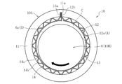
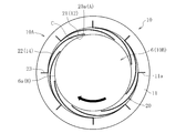
- FIG. 3 shows a cross-sectional view perpendicular to the axis of the foil bearing 10 according to one embodiment of the present invention.
- a foil bearing 10 shown in the figure is also called a bump type, and is formed of a cylindrical outer member 11 fixed to the inner periphery of a casing (not shown) and an iron-based metal material. 11 and a top foil 12 and a back foil 13 held (fixed) on the inner periphery of the outer member 11.
- the outer member 11, the top foil 12 and the back foil 13 held by the outer member 11 constitute a stationary member 10A
- the shaft 6 constitutes a rotating member 10B.
- a first bearing surface A is provided on the inner peripheral surface 12a of the top foil 12, and a wedge-shaped radial bearing gap C is provided between the outer peripheral surface 6a of the shaft 6 and the first bearing surface A when the shaft 6 rotates.
- a second bearing surface B is provided.
- both bearing surfaces A and B are formed as smooth surfaces without minute irregularities.
- the top foil 12 is formed into a cylindrical shape having a circumferential end by rounding a flexible iron-based metal strip having a thickness of about 20 to 200 ⁇ m, for example, and is bent at one end in the circumferential direction.
- the outer member 11 is held by fitting the portion 12 b into the groove 11 a of the outer member 11.
- the back foil 13 is formed into a cylindrical shape having a circumferential end by rolling a flexible iron-based metal strip having a thickness of about 20 to 200 ⁇ m.
- the bent portion 13 a formed at one end portion in the direction is fitted to the groove portion 11 a of the outer member 11 and fixed to the outer member 11.
- the back foil 13 has an elastic support portion 14 that elastically supports the top foil 12, and the elastic support portion 14 in the illustrated example is configured by alternately arranging arcuate convex portions 14a and concave portions 14b in the circumferential direction. ing.
- the top foil 12 and the back foil 13 may be provided with a retaining means to prevent the outer member 11 from coming off.
- a retaining means for example, a flange portion that is engaged with the end face of the outer member 11 in the axial direction can be employed.
- the foil member a member in which the top foil 12 and the back foil 13 are integrally provided can be used.
- the rotation direction of the shaft 6 is a direction in which the gap width of the circumferential gap between the circumferential one end and the other circumferential end of the top foil 12 and the back foil 13 is increased. That is, the foil bearing 10 shown in FIG. 3 supports the shaft 6 that rotates clockwise as indicated by a black arrow in the drawing.
- the shaft 6 when the shaft 6 rotates, the space between the first bearing surface A provided on the inner peripheral surface 12a of the top foil 12 and the second bearing surface B provided on the outer peripheral surface 6a of the shaft 6 is increased. A wedge-shaped radial bearing gap C is formed.
- the rotational speed of the shaft 6 is increased and the pressure of the air film generated in the radial bearing gap C is sufficiently increased, the shaft 6 is supported in a non-contact manner so as to be rotatable in the radial direction with respect to the outer member 11.
- the flexible top foil 12 While the shaft 6 is rotating, the flexible top foil 12 is appropriately elastically deformed according to changes in the load (air film pressure) acting on the first bearing surface A, the ambient temperature, etc.
- the gap width of the radial bearing gap C is automatically adjusted to an appropriate width according to the operating conditions. By such a function of automatically adjusting the gap width, the rotation of the shaft 6 is stably supported.
- the radial width of the radial bearing gap C is exaggerated for easy understanding.
- the top foil 12 is elastically supported by the elastic support portion 14 provided on the back foil 13, the top foil 12 and the back foil 13 (elastic support portion 14), and further, the back foil 13 and the outer member 11.
- the automatic adjustment function of the radial width of the radial bearing gap C can be enhanced, and vibration generated with the rotation of the shaft 6 can be effectively damped. . Therefore, the radial width of the radial bearing gap C can be managed within an appropriate range even under severe operating conditions such as high temperature and high speed rotation, and the rotation of the shaft 6 is supported more stably.
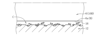
- a powder 16 (hereinafter, referred to as “ Lubricating powder 16 ”) is interposed.
- the lubricating powder 16 is made of a material different from the base material of the shaft 6 and the top foil 12 and is not melted or decomposed in a high temperature atmosphere where the foil bearing 10 is used.
- the lubricating powder 16 is oxidized.
- Iron powder is used.
- the iron oxide powder as the lubricating powder 16 is the top as the two bearing surfaces A and B are repeatedly in sliding contact after the foil bearing 10 starts operating until the shaft 6 reaches a steady rotation state.
- Metal wear powder (iron-based powder) generated by wear of at least one of the base material of the foil 12 and the shaft 6 is oxidized by touching the air in the radial bearing gap C.
- the top foil 12 is elastically deformed in the width direction of the bearing gap (radial direction in the present embodiment) according to the pressure of the air film generated in the radial bearing gap C at least partially.
- a first state (see FIG. 5) in which a holding part 17 capable of holding the lubricating powder 16 interposed between the bearing surfaces A and B is formed, and a second state in which the holding part 17 substantially disappears ( Between the second state and the first state as the pressure of the air film increases (from the first state to the second state as the pressure of the air film decreases). To be migrated).
- the top foil 12 (first bearing surface A) receives the pressure of the air film.
- At least a portion (here, a portion disposed on the inner diameter side of the concave portion 14b constituting the elastic support portion 14) is elastically deformed radially outward to form a concave holding portion 17, and this holding portion 17, the lubricating powder 16 interposed between the bearing surfaces A and B is held (see FIG. 5).
- the first bearing surface A of the top foil 12 has a smooth cylindrical surface shape (the holding portion 17 substantially disappears), and the lubricating powder 16 freely disperses and floats between the bearing surfaces A and B. (See FIG. 4).
- the first bearing surface A is changed to the second bearing surface B. And can be preferentially brought into contact with the lubricating powder 16 interposed between the bearing surfaces A and B.
- the frictional force between the bearing surfaces A and B can be reduced to achieve low torque.
- transformation and seizure of both bearing surfaces A and B accompanying this can also be prevented effectively. .
- the average particle size of the lubricating powder 16 interposed between the bearing surfaces A and B is equal to or greater than the surface roughness of both the bearing surfaces A and B (the arithmetic average roughness specified in JIS B 0601), and the shaft It is preferable that the thickness of the air film formed in the radial bearing gap C is equal to or less than the thickness of the air bearing 6 at the time of steady rotation (fluid lubrication region).
- the stationary side member and the rotating side member both bearing surfaces A and B
- the top foil 12 is in a second state (see FIG. 4) in which the lubricating powder 16 can be freely dispersed and suspended between the bearing surfaces A and B.
- the lubricating powder 16 interposed between the bearing surfaces A and B functions as a spacer, so that not only the frictional force between the bearing surfaces is reduced, but also a space is created between the bearing surfaces A and B. This makes it easier to draw air between the bearing surfaces A and B.
- the foil bearing 10 starts operating, a steady rotation state can be quickly realized without requiring large energy. Accordingly, the starting torque can be greatly reduced, and the rotational speed required to support the shaft 6 in a non-contact manner is reduced, so that the load on both the bearing surfaces A and B is reduced and the durability is improved.
- the lubricating powder 16 is not always held by the holding portion 17 during steady rotation of the shaft 6, that is, when the top foil 12 is in the first state (see FIG. 5). It is thought that it adheres to one or both of both bearing surfaces A and B, or floats and flows in the radial bearing gap C.
- the foil bearing 10 employs air having a lower viscosity than a liquid such as lubricating oil as the lubricating fluid, the lubricating powder 16 adhering to the bearing surfaces A and B causes the flow force of the lubricating fluid. Even if it receives, the lubricating powder 16 is hard to peel off from the bearing surfaces A and B.
- the foil bearing 10 when the start / stop is repeated, the sliding contact between the lubricating powder 16 and both the bearing surfaces A and B, and the lubricating powder by the both bearing surfaces A and B are performed. Since the pressurization and the like of 16 are repeated, it is considered that the lubricating powder 16 adheres and accumulates on one or both of the bearing surfaces A and B to form a lubricating coating. Thereby, low torque can be realized in all lubrication regions (rotational speed regions). Accordingly, the foil bearing 10 having a lower torque and a longer life can be realized.
- the lubricating powder 16 is simply interposed between the bearing surfaces A and B without providing the top foil 12 with the function of switching the holding / non-holding of the lubricating powder 16 as in the present invention. It is possible to reduce the torque of the foil bearing 10 and the like. However, if the lubricating powder 16 is excessively interposed between the bearing surfaces A and B, the volume ratio of the lubricating powder 16 to the air in the radial bearing gap C is increased, particularly during steady rotation. There is a possibility that the rigidity of the air film formed in the radial bearing gap C will be reduced, that is, the supporting ability may be reduced.
- the bearing surfaces A and B may bite the lubricating powder 16 and may adversely affect the bearing function itself. Therefore, as shown in FIG. 5, during steady rotation (fluid lubrication region), the lubricating powder 16 is held by the holding portion 17, and the supply amount (dispersion amount) of the lubricating powder 16 to the radial bearing gap C is maintained.
- a sufficient amount of the lubricating powder 16 can be interposed between the bearing surfaces A and B in the stop to low speed rotation state (mixed lubrication region / boundary lubrication region) shown in FIG. It is preferable to give the function to the top foil 12.
- the top foil 12 is formed of a flexible metal thin plate and can be arbitrarily elastically deformed according to the pressure of the air film, the above-described top foil 12 can be obtained by simply adjusting the shape of the elastic support portion 14 and the like. The effects can be enjoyed easily and effectively.
- FIG. 6A is an example thereof, and a plurality of minute protrusions 18 are provided on the first bearing surface A of the top foil 12.
- the contact area between the bearing surfaces A and B can be reduced to achieve low torque, and the space between the bearing surfaces A and B is formed, so that both bearing surfaces A and B are formed. Since it becomes easy to draw air between B, it becomes possible to reduce starting torque. Further, at the time of sliding contact between both the bearing surfaces A and B, a high surface pressure acts on the protrusion 18, so that the wear powder and, consequently, the lubricating powder 16 are quickly interposed between the both bearing surfaces A and B. (See FIG. 6B). In addition, if the height and the number of installations of the protrusions 18 are adjusted, the particle diameter and amount of the lubricating powder 16 (the lubricating powder 16 made of oxide of wear powder) to be interposed between the bearing surfaces A and B. Can be controlled.
- At least one of the first bearing surface A and the second bearing surface B may be provided on a lubricating coating formed on the base material (base material surface). That is, a lubricating coating may be provided on a portion of the inner peripheral surface 12a of the top foil 12 and the outer peripheral surface 6a of the shaft 6 that faces at least one radial bearing gap C, and the bearing surface may be configured by this lubricating coating. In this way, in particular, both bearings at the start of use of the foil bearing 10 in which the shaft 6 and the top foil 12 are formed of the same material and the lubricating powder 16 is not interposed between the bearing surfaces A and B.
- both bearing surfaces A and B can be effectively prevented from being severely worn and causing fatal defects such as adhesion at the sliding contact portions of both. it can.
- the lubricating coating does not require special wear resistance and may be worn at an early stage. Since the abrasion powder of the lubricating coating exhibits a lubricating action, even if the base material of the shaft 6 and the top foil 12 is worn, the situation where the wear becomes mild wear and leads to adhesion is avoided. The generated fine wear powder of the base material is immediately oxidized and functions as the lubricating powder 16.
- lubricating coatings can be employed.
- powders for example, molybdenum disulfide powder, tungsten disulfide, etc.
- abrasion powder functions as the lubricating powder 16.
- a film having excellent wear resistance such as a DLC film Can be adopted.
- the DLC film is formed, it is preferably formed on the outer peripheral surface 6a of the shaft 6, not on the inner peripheral surface 12a of the top foil 12 formed of a thin metal plate.
- a protrusion 18 can be provided.
- the lubricating powder 16 interposed between the bearing surfaces A and B may include a solid lubricant powder different from the wear powder of the top foil 12 and the base material of the shaft 6. . That is, solid lubricant powder may be interposed between the bearing surfaces A and B of the foil bearing 10 (new foil bearing 10) before use. In this way, since the lubricating powder 16 can be interposed between the bearing surfaces A and B from the start of use of the new foil bearing 10, the above-described effects can be enjoyed effectively.
- the average particle size is equal to or greater than the surface roughness of both bearing surfaces A and B (arithmetic average roughness specified in JIS B 0601) and is steady. It is preferable to use one having a thickness equal to or less than the thickness of the air film formed in the radial bearing gap C during rotation.
- the solid lubricant powder when solid lubricant powder is interposed between the bearing surfaces A and B in advance, if the hardness is higher than the base material hardness of the top foil 12 or the shaft 6, the solid lubricant powder functions as abrasive grains. In addition, the generation of the wear powder of the base material and the oxide powder (lubricating powder 16) thereof is promoted. On the other hand, if the hardness of the solid lubricant powder is about the same as that of the top foil 12 or the base material of the shaft 6 or lower than that of the base material, there is an advantage that a reduction in torque can be realized from the beginning of use of the foil bearing 10. From the above, there is no particular restriction on the solid lubricant powder used in this case.
- powder of metal oxide such as iron oxide (Fe 2 O 3 ) or alumina (Al 2 O 3 ), molybdenum disulfide (MoS) 2 ), powders of sulfides such as tungsten disulfide (WS 2 ), powders of soft metals such as copper (Cu), silver (Ag), tin (Sn), zinc (Zn), carbon represented by graphite powder System powders
- MoS molybdenum disulfide
- WS 2 powders of sulfides
- powders of soft metals such as copper (Cu), silver (Ag), tin (Sn), zinc (Zn)
- carbon represented by graphite powder System powders can be used.
- the solid lubricant powder exemplified above only one kind may be used, or a plurality of kinds may be mixed and used.
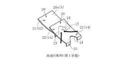
- FIG. 7 shows an example of a leaf-type foil bearing 10 that supports a radial load, and includes an outer member 11 and a plurality (eight in the illustrated example) of leaves 20 fixed to the outer member 11. 10 A of stationary side members are comprised.
- Each leaf 20 has a rear end 22 provided with a bent portion 23 fixed to the groove portion 11a of the outer member 11, and a front end 21 which is separated from the rear end 22 in the circumferential direction and becomes a free end, A region including the front end 21 of the leaf 20 functions as the top foil 12, and a region including the rear end 22 of each leaf 20 functions as the elastic support portion 14.
- the first bearing surface A provided on the inner diameter surface on the front end 20a side of each leaf 20 and the outer peripheral surface 6a (second bearing surface B) of the shaft 6 opposed to the first bearing surface A are disposed.
- a wedge-shaped radial bearing gap C is formed, and the shaft 6 is supported in the radial direction by the pressure of the air film generated in each radial bearing gap C.
- each leaf 20 functioning as the top foil 12 has a radial bearing gap C as in the bump type foil bearing 10 mainly shown in FIGS.
- the lubricating powder 16 is interposed between the bearing surfaces A and B, as in the bump type foil bearing 10 shown in FIG. Can do.
- the top foil 12 (leaf 20) and the shaft are associated with the sliding contact of both the bearing surfaces A and B.
- Oxide (only) of wear powder generated by wear of at least one of the base material of 6 may contain a solid lubricant powder different from the wear powder of the base material of leaf 20 and shaft 6 May be used.
- at least one of both bearing surfaces A and B may be provided with a minute projection 18 (see FIG.
- each leaf 20 is accompanied by an increase in the pressure of the air film generated in the radial bearing gap C (as the front end 21 side of the leaf 20 is elastically deformed radially outward).
- a holding portion 17 formed between two adjacent leaves 20 and 20 may be provided with a drawing portion 24 that can positively draw the lubricating powder 16 interposed between both bearing surfaces A and B.
- the manner in which the pulling force acts is indicated by a black arrow in FIG. 8B).
- a V-shaped notch formed on the rear end 22 side of the leaf 20 (more specifically, a V-shaped notch whose width is gradually reduced toward the front side in the rotational direction of the shaft 6).
- the retraction part 24 is comprised by.
- the present invention is applied to the foil bearing 10 in which the top foil 12 and the elastic support portion 14 are provided on the outer member 11 constituting the stationary member 10A.
- the present invention is applied to the top foil 12 and the elastic support portion 14.
- the present invention can be applied to the foil bearing 10 in which the outer member 11 constitutes the rotation side member 10B and the shaft 6 constitutes the stationary side member 10A (not shown).
- the present invention is not limited to the type of foil bearing 10 that supports a radial load as described above, but also a type of foil bearing that supports a thrust load (for example, the thrust bearing shown in FIG. 2). 30).
- the foil bearing according to the present invention can be preferably used not only for supporting a rotor of a turbo machine such as a micro gas turbine but also for supporting another rotating body.
- a new foil bearing is prepared as a specimen, and solid lubricant powder is interposed in advance between the inner peripheral surface of the top foil and the outer peripheral surface of the shaft (between both bearing surfaces), and then the foil bearing is operated for a predetermined time.
- solid lubricant powder As a result, it was confirmed and investigated how much the amount of wear on the bearing surface (base material) varies depending on the type of solid lubricant powder interposed between both bearing surfaces. The results of the investigation are shown in FIG.
- the top foil constituting the foil bearing and the shaft inserted into the inner periphery thereof were both made of an iron-based metal material.
- solid lubricant powder alumina, iron oxide, copper, silver, and molybdenum disulfide powder were prepared.
- the top foil does not cause fatal defects such as breakage due to sliding contact with the shaft, and the wear amount of the base material (total weight of the wear powder) ) Can be suppressed within a range that does not adversely affect the bearing performance of the foil bearing.
- the soft metal powder especially copper powder is effective in reducing the torque and extending the life of the foil bearing.
- the wear amount of the base material was the smallest when iron oxide powder was used as the solid lubricant powder.
- the top foil and shaft are made of iron-based metal material, so the iron oxide powder previously interposed between both bearing surfaces as the solid lubricant powder is the base material of the top foil and shaft.
- This powder is the same type as the lubricating powder produced by oxidation of the wear powder. Therefore, it can be said that the oxide of the top foil and the shaft base material contributes particularly effectively in reducing the friction of both bearing surfaces, that is, reducing the torque and extending the life of the foil bearing.
- the solid lubricant powder was interposed between the bearing surfaces.
- the bearing surfaces is composed of a lubricant film in which the solid lubricant powder is dispersed, It is thought that the effect can be enjoyed.
Landscapes
- Engineering & Computer Science (AREA)
- General Engineering & Computer Science (AREA)
- Mechanical Engineering (AREA)
- Physics & Mathematics (AREA)
- Fluid Mechanics (AREA)
- Support Of The Bearing (AREA)
- Supercharger (AREA)
- Sliding-Contact Bearings (AREA)
Abstract
可撓性を有する金属薄板で形成されたトップフォイル12を備え、軸6の回転に伴ってトップフォイル12に設けた第1軸受面Aと軸6に設けた第2軸受面Bとの間のラジアル軸受隙間Cに空気膜が形成され、その圧力で軸6が支持されるフォイル軸受10において、両軸受面A,B間に潤滑性粉体16が介在しており、トップフォイル12は、その一部がラジアル軸受隙間Cに生じる空気膜の圧力に応じてラジアル軸受隙間Cの幅方向に弾性変形することにより、潤滑性粉体16を保持可能な保持部17が形成される第1状態と、保持部17が実質的に消滅する第2状態との間を相互に移行し、かつ、空気膜の圧力上昇に伴って第2状態から第1状態に移行する。
Description
本発明は、フォイル軸受に関する。
ターボ機械(例えばガスタービンやターボチャージャ)の主軸は高温環境下で高速回転する。また、ターボ機械では、エネルギー効率の観点から油循環用の補機を別途設けることが困難な場合がある他、潤滑油のせん断抵抗が主軸の高速回転化の阻害要因となる場合がある。そのため、ターボ機械の主軸の支持用軸受としては、油潤滑の転がり軸受や動圧軸受ではなく空気動圧軸受を使用する場合が多い。
空気動圧軸受としては、回転側の軸受面と静止側の軸受面の双方を剛体で構成したものが一般的である。しかしながら、この種の空気動圧軸受では、両軸受面間に形成される軸受隙間の隙間幅管理が不十分であると、安定限界を超えた際にホワールと称される自励的な主軸の振れ回りが生じ易くなる。従って、一般的な空気動圧軸受において、所望の軸受性能を安定的に発揮するには、軸受隙間の隙間幅を高精度に管理する必要があるが、ターボ機械のように温度変化の大きい環境では、熱膨張の影響で軸受隙間の隙間幅が変動し易いため、所望の軸受性能を安定的に発揮するのが困難である。
ホワールが生じ難く、かつ温度変化の大きい環境下でも軸受隙間の隙間幅管理を容易にできる軸受としてフォイル軸受が知られている。フォイル軸受は、曲げに対して剛性の低い可撓性を有する金属薄板(フォイル)で軸受面を構成し、この軸受面のたわみを許容することで荷重を支持するものである。例えば下記の特許文献1に、ラジアル荷重を支持するタイプのフォイル軸受が開示されている。
特許文献1のフォイル軸受では、回転軸が回転すると、静止側を構成するトップフォイル(軸受フォイル)の内径面とこれに対向する回転軸の外周面との間のラジアル軸受隙間に空気膜が形成され、その圧力で回転軸がラジアル方向に支持される。そして、このフォイル軸受では、トップフォイルに作用する荷重や周囲温度などといった運転条件に応じてトップフォイル、およびトップフォイルを弾性的に支持する弾性支持部(弾性体)が弾性変形することにより、ラジアル軸受隙間の隙間幅が自動調整される。そのため、フォイル軸受は、一般的な動圧軸受と比較して安定性に優れるという特徴があり、ターボ機械のロータのように、高温環境下で高速回転する回転体の支持用軸受として好適に用い得る。
また、一般的な動圧軸受では、ラジアル軸受隙間の隙間幅を軸径の1/1000のオーダーで管理する必要があることから、例えば直径が数mm程度の回転軸の支持用途に一般的な動圧軸受を用いた場合、ラジアル軸受隙間の隙間幅を数μm程度に管理する必要がある。しかしながら、製造時の公差や熱膨張量を考慮すると、上記オーダーでの隙間幅管理を行うことは容易ではない。これに対してフォイル軸受では、トップフォイル(軸受面)自体が弾性変形することによってラジアル軸受隙間の隙間幅が自動調整されるため、ラジアル軸受隙間の隙間幅を数十μm程度に管理すれば足りる。従って、フォイル軸受は、一般的な動圧軸受に比べ、製造や軸受隙間の隙間幅管理を容易化できるという利点も有する。
なお、以上で述べたフォイル軸受の利点は、スラスト荷重を支持するタイプのフォイル軸受においても同様に享受される。
ところで、特に回転軸の低速回転時には、軸受隙間に形成される空気膜の剛性(圧力)が十分に高まっていないため、両軸受面が繰り返し摺動接触する。このような摺動接触に伴う軸受面の摩耗や回転トルクの上昇を可及的に防止するため、両軸受面の少なくとも一方に、ニッケルめっきやクロムめっき等の耐摩耗性に優れた被膜、あるいは、二硫化モリブデン、黒鉛、フッ素樹脂等の固体潤滑剤を分散しためっき被膜や樹脂コーティング等の潤滑性の良い被膜を設けることも検討されている(特許文献1参照)。
上述のフォイル軸受をはじめとする各種のフォイル軸受は、一層の低トルク化や長寿命化を実現することが求められている。しかしながら、両軸受面の少なくとも一方に上記のような被膜を形成しても、このような要請への対応策としては不十分であることが判明した。
そこで、本発明は、一層の低トルク化、さらには長寿命化を図ることのできるフォイル軸受を提供することを目的とする。
上記の目的を達成するために創案された本発明は、静止側部材又は回転側部材の何れか一方が、可撓性を有する金属薄板で形成されたトップフォイルと、トップフォイルを弾性的に支持する弾性支持部とを備え、回転側部材の回転に伴ってトップフォイルに設けた第1軸受面とこれに対向する他方の部材の第2軸受面との間の軸受隙間に空気膜が形成され、その圧力で回転側部材が支持されるフォイル軸受において、第1軸受面と第2軸受面との間に潤滑性を有する粉体が介在しており、トップフォイルは、少なくともその一部が空気膜の圧力に応じて軸受隙間の幅方向に弾性変形することにより、上記粉体を保持可能な保持部が形成される第1状態と、上記保持部が実質的に消滅する第2状態との間を相互に移行し、かつ、空気膜の圧力上昇に伴って上記第2状態から上記第1状態に移行することを特徴とする。
なお、本発明でいう軸受隙間とは、ラジアル軸受隙間あるいはスラスト軸受隙間の別を問わない。すなわち、本発明は、ラジアル荷重を支持するタイプのフォイル軸受、あるいはスラスト荷重を支持するタイプのフォイル軸受の何れにも適用可能である。
上記構成によれば、フォイル軸受の起動直後や停止直前時等、軸受隙間に形成される空気膜の圧力が低い状態(混合潤滑域や境界潤滑域)においては、第1軸受面を、第2軸受面ではなく、両軸受面間に介在させた潤滑性を有する粉体(以下「潤滑性粉体」ともいう)と優先的に接触させることができる。これにより、両軸受面間の摩擦力を低減して低トルク化を達成することができ、軸受面同士の摺動接触による軸受面の局所的な温度上昇、およびこれに伴う軸受面の変形や焼付きを効果的に防止することができる。また、一般的なフォイル軸受の停止時、両軸受面は、通常、少なくとも一部が接触状態にあることから、軸受の運転開始後、定常回転状態(流体潤滑域)に至るまでに大きなエネルギーが必要となる。これに対し、本発明に係るフォイル軸受の停止時には、トップフォイルが、上記保持部が実質的に消滅した第2状態にある関係上、両軸受面間に介在させた潤滑性粉体がスペーサとして機能し、両軸受面間の摩擦力を減じるだけでなく、両軸受面間に空間を作ることで軸受面間に空気を引き込み易くなる。そのため、軸受の運転開始後、大きなエネルギーを必要とすることなく、迅速に定常回転状態を実現することができる。従って、始動トルクを大幅に減じることができる他、回転側の部材を非接触支持するのに必要となる回転速度が下がるので、両軸受面への負荷が減じられて耐久性が向上する。
両軸受面間に介在する潤滑性粉体は、回転側部材の定常回転時、すなわちトップフォイルが第1状態にあるときにおいてもその全てが保持部で保持されるわけではなく、少なくとも一部が潤滑流体(空気)と共に軸受隙間内を流動するか、もしくは両軸受面の何れか一方に付着した状態にあると考えられる。そのため、定常回転時に何らかの拍子に軸受面同士が摺動接触した場合でも、軸受面の局所的な温度上昇、およびこれに伴う軸受面の変形や焼付きを効果的に防止することができる。また、本発明に係るフォイル軸受の起動・停止が繰り返されると、潤滑性粉体と軸受面との摺動接触や両軸受面による潤滑性粉体の加圧等が繰り返され、その結果、潤滑性粉体は両軸受面の何れか一方又は双方に付着・堆積して潤滑性に優れた被膜を形成すると考えられる。これにより、全ての潤滑域(回転速度域)において低トルク化を実現することができる。以上より、一層低トルクで長寿命のフォイル軸受を実現することができる。
ここで、本発明のように潤滑性粉体の保持/非保持の切り替え機能をトップフォイルに付与することなく、単に両軸受面間に潤滑性粉体を介在させておくだけでもフォイル軸受の低トルク化等を実現できると考えられる。しかしながら、両軸受面間に過剰に潤滑性粉体が介在していると、軸受隙間内の潤滑流体(空気)に占める潤滑性粉体の体積比率が増大する分、特に定常回転時に軸受隙間に形成される空気膜の剛性低下、すなわち支持能力低下を招来する可能性がある。また、多量の粉体が一度に軸受隙間に入り込むことで、軸受面に噛みこみ、軸受機能そのものに悪影響を及ぼすことが考えられる。そのため、本発明のように、定常回転時(流体潤滑域)においては潤滑性粉体を保持して軸受隙間への潤滑性粉体の供給量を制限できる一方で、主に、軸受の停止~低速回転状態(混合潤滑域・境界潤滑域)においては十分量の潤滑性粉体を両軸受面間に介在させ得るような機能をトップフォイルに付与しておけば、定常回転時における支持能力低下を招来することなく、低速回転時等における十分な低摩擦化・低トルク化を実現することができる。そして、トップフォイルは可撓性を有する金属薄板で形成され、空気膜の圧力に応じて任意に弾性変形させ得ることから、例えば弾性支持部の形状等を適宜調整するだけで上述の作用効果を容易かつ有効に享受することができる。
潤滑性粉体としては、例えば、両軸受面の摺動接触に伴ってトップフォイルおよび他方の部材(例えば軸)の母材の少なくとも一方が摩耗することにより生じた摩耗粉の酸化物を使用することができる。但し、この場合、フォイル軸受の使用開始段階(新品のフォイル軸受の使用初期)においては、両軸受面間に潤滑性粉体が介在せず、無潤滑の状態で両軸受面が摺動接触するので、始動トルクや低速回転時における回転トルクが高くなる他、軸受隙間を形成する二部材(例えば、トップフォイルおよび軸)の母材が激しく摩耗する可能性がある。このような問題を可及的速やかに解消する、あるいは上記問題の発生を回避するための技術手段としては、以下の(1)~(3)の少なくとも一つを採用することが考えられる。
・ 両軸受面の少なくとも一方に、他方の軸受面側に突出した突起部を設ける。
(2)潤滑性粉体に、トップフォイルおよび他方の部材の母材の摩耗粉とは異なる固体潤滑剤を含める。
(3)第1軸受面と第2軸受面の少なくとも一方を母材上に形成した潤滑被膜に設ける。
・ 両軸受面の少なくとも一方に、他方の軸受面側に突出した突起部を設ける。
(2)潤滑性粉体に、トップフォイルおよび他方の部材の母材の摩耗粉とは異なる固体潤滑剤を含める。
(3)第1軸受面と第2軸受面の少なくとも一方を母材上に形成した潤滑被膜に設ける。
すなわち、上記(1)の構成を採用すれば、軸受面同士の接触面積が減じられて低トルク化を達成できる他、両軸受面の摺動接触時においては突起部に高面圧が作用して早々に微小な摩耗粉が発生するため、両軸受面間に潤滑性粉体を迅速に介在させることが可能となる。また、上記(2)の構成を採用すれば、フォイル軸受の使用開始段階から両軸受面間に潤滑性粉体を介在させることができるので、フォイル軸受の使用開始段階における始動トルクや低速回転時における回転トルクを減じることができる他、母材の摩耗もマイルド摩耗となり、発生する摩耗粉の酸化物も潤滑性粉体として機能する。また、上記(3)の構成を採用すれば、潤滑被膜が摩耗することによって潤滑性粉体を生成することができるので、フォイル軸受の使用開始段階における始動トルクや低速回転時における回転トルクを減じることができる他、母材の摩耗もマイルド摩耗となり、発生する摩耗粉の酸化物も潤滑性粉体として機能する。
本発明に係るフォイル軸受は、以上のような特徴を有することから、ターボ機械(例えば、ガスタービンやターボチャージャ)のロータ等、高速回転する回転側部材の支持用軸受として好ましく用いることができる。
以上より、本発明によれば、一層の低トルク化、さらには長寿命化を達成することのできるフォイル軸受を実現することができる。
以下、本発明の実施の形態を図面に基づいて説明する。
図1に、ターボ機械の一例として、マイクロガスタービンと称されるガスタービン装置の構成を概念的に示す。このガスタービン装置は、主要な構成として、翼列を形成したタービン1と、圧縮機2と、発電機3と、燃焼器4と、再生器5とを備え、タービン1および圧縮機2は、水平方向に延びる軸6に取り付けられて軸6と共に回転側のロータを構成する。軸6の軸方向一端は発電機3に連結されている。このマイクロガスタービンが運転されると、吸気口7から空気が吸入され、吸入された空気は、圧縮機2で圧縮されると共に再生器5で加熱された上で燃焼器4に送り込まれる。燃焼器4は、圧縮・加熱された空気に燃料を混合してこれを燃焼させることにより高温・高圧のガスを発生させ、このガスによりタービン1を回転させる。タービン1が回転すると、その回転力が軸6を介して発電機3に伝達され、発電機3が回転駆動される。発電機3が回転駆動することにより生じた電力は、インバータ8を介して出力される。タービン1を回転させた後のガスは比較的高温であるため、このガスを再生器5に送り込んで燃焼前の圧縮空気との間で熱交換を行うことで、燃焼後のガスの熱を再利用する。再生器5で熱交換を終えたガスは、排熱回収装置9を通ってから排ガスとして排出される。
図2に、図1に示したマイクロガスタービンにおけるロータの支持構造の一例を概念的に示す。この支持構造では、軸6の軸方向に離間した二箇所にラジアル軸受10が配置され、軸6に設けたフランジ部6bの軸方向両側にスラスト軸受30,30が配置される。これらラジアル軸受10およびスラスト軸受30により、軸6がラジアル方向およびスラスト両方向に回転自在に支持される。この支持構造において、タービン1と圧縮機2の間の領域は、高温・高圧のガスで回転されるタービン1に隣接している関係上高温雰囲気となる。加えて、軸6は、数万rpm以上の回転速度で回転する。そのため、この支持構造で使用する軸受10,30としては、空気動圧軸受、特にフォイル軸受が適合する。
以下、本発明の実施の形態であって、上記のマイクロガスタービン用のラジアル軸受10に適合するフォイル軸受を図面に基づいて説明する。なお、以下では、ラジアル軸受10に適合するフォイル軸受を「フォイル軸受10」という。
図3に、本発明の一実施形態に係るフォイル軸受10の軸直交断面図を示す。同図に示すフォイル軸受10は、バンプ型とも称されるものであり、図示しないケーシングの内周に固定される円筒状の外方部材11と、鉄系の金属材料で形成され、外方部材11の内周に挿入された軸6と、外方部材11の内周に保持(固定)されたトップフォイル12およびバックフォイル13とを備える。本実施形態では、外方部材11と、外方部材11に保持されたトップフォイル12およびバックフォイル13とが静止側部材10Aを構成し、軸6が回転側部材10Bを構成する。トップフォイル12の内周面12aには第1軸受面Aが設けられ、軸6の外周面6aには、軸6の回転時に、第1軸受面Aとの間にくさび状のラジアル軸受隙間Cを形成する第2軸受面Bが設けられる。本実施形態において、両軸受面A,Bは、何れも、微小な凹凸のない平滑面に形成されている。
トップフォイル12は、例えば、厚さ20~200μm程度の可撓性を有する鉄系金属の帯板を丸めることによって周方向で有端の円筒状に形成され、その周方向一端部に形成した折り曲げ部12bを外方部材11の溝部11aに嵌合することで外方部材11に保持されている。また、バックフォイル13は、トップフォイル12と同様に、厚さ20~200μm程度の可撓性を有する鉄系金属の帯板を丸めることによって周方向で有端の円筒状に形成され、その周方向一端部に形成した折り曲げ部13aを外方部材11の溝部11aに嵌合することで外方部材11に固定されている。バックフォイル13は、トップフォイル12を弾性的に支持する弾性支持部14を有し、図示例の弾性支持部14は円弧状の凸部14aおよび凹部14bを周方向で交互に配して構成されている。
図示は省略するが、トップフォイル12およびバックフォイル13には、外方部材11からの抜けを防止するため抜け止め手段を設けても良い。抜け止め手段としては、例えば、外方部材11の端面と軸方向で係合するフランジ部を採用できる。また、フォイル部材としては、トップフォイル12とバックフォイル13が一体的に設けられたものを用いることもできる。
軸6の回転方向は、トップフォイル12およびバックフォイル13の周方向一端部と周方向他端部との間の周方向隙間の隙間幅が拡大する方向とされる。すなわち、図3に示すフォイル軸受10は、同図中に黒塗り矢印で示すように、時計回りに回転する軸6を支持する。
以上の構成からなるフォイル軸受10において、軸6が回転すると、トップフォイル12の内周面12aに設けた第1軸受面Aと軸6の外周面6aに設けた第2軸受面Bとの間にくさび状のラジアル軸受隙間Cが形成される。そして、軸6の回転速度が上がり、ラジアル軸受隙間Cに生じる空気膜の圧力が十分に高まると、軸6が外方部材11に対してラジアル方向に回転自在に非接触支持される。
軸6の回転中には、可撓性を有するトップフォイル12が、第1軸受面Aに作用する荷重(空気膜の圧力)や周辺温度等が変化するのに応じて適宜弾性変形するため、ラジアル軸受隙間Cの隙間幅が運転条件に応じた適正幅に自動調整される。このような隙間幅の自動調整機能により、軸6の回転が安定的に支持される。なお、図3においては理解の容易化のためラジアル軸受隙間Cの隙間幅を誇張して描いている。
また、トップフォイル12がバックフォイル13に設けた弾性支持部14によって弾性的に支持されていること、トップフォイル12とバックフォイル13(弾性支持部14)、さらにはバックフォイル13と外方部材11が互いに摺動可能であること、などの理由から、ラジアル軸受隙間Cの隙間幅の自動調整機能が強化されると共に、軸6の回転に伴って発生する振動を効果的に減衰することができる。そのため、高温・高速回転といった過酷な運転条件でもラジアル軸受隙間Cの隙間幅を適正範囲内に管理することができ、軸6の回転が一層安定的に支持される。
このフォイル軸受10では、図4,5に拡大して示すように、第1軸受面Aと第2軸受面Bとの間(ラジアル軸受隙間C)に潤滑性を有する粉体16(以下、「潤滑性粉体16」という)が介在している。潤滑性粉体16は、軸6およびトップフォイル12の母材とは異なる材料からなり、かつフォイル軸受10が使用される高温雰囲気下で溶融・分解等しないものが使用され、本実施形態では酸化鉄粉末が使用される。潤滑性粉体16としての酸化鉄粉末は、フォイル軸受10の運転開始後、軸6が定常回転状態に至るまでの間に、両軸受面A,Bが繰り返し摺動接触するのに伴ってトップフォイル12および軸6の少なくとも一方の母材が摩耗することで生じた金属の摩耗粉(鉄系粉末)がラジアル軸受隙間C内の空気に触れて酸化したものである。
また、このフォイル軸受10において、トップフォイル12は、少なくともその一部がラジアル軸受隙間Cに生じる空気膜の圧力に応じて軸受隙間の幅方向(本実施形態では径方向)に弾性変形することにより、両軸受面A,B間に介在する潤滑性粉体16を保持可能な保持部17が形成される第1状態(図5参照)と、保持部17が実質的に消滅する第2状態(図4参照)との間を相互に移行し、かつ、空気膜の圧力上昇に伴って第2状態から第1状態に移行する(空気膜の圧力低下に伴って第1状態から第2状態に移行する)ように構成されている。
より詳細に述べると、軸6の定常回転時のように、ラジアル軸受隙間Cに生じる空気膜の圧力が十分に高まった状態では、空気膜の圧力を受けてトップフォイル12(第1軸受面A)の少なくとも一部(ここでは、弾性支持部14を構成する凹部14bの内径側に配置される部分)が径方向外向きに弾性変形することによって凹状の保持部17が形成され、この保持部17にて両軸受面A,B間に介在させた潤滑性粉体16が保持される(図5参照)。一方、軸6の停止状態や、軸6の起動直後・停止直前時のように軸6の回転速度が十分に上がらず、ラジアル軸受隙間Cに生じる空気膜の圧力が十分に高まっていない状態では、トップフォイル12の第1軸受面Aが平滑な円筒面状をなし(保持部17が実質的に消滅し)、潤滑性粉体16が両軸受面A,B間で自由に分散・浮遊するように構成されている(図4参照)。
従って、以上の構成によれば、ラジアル軸受隙間C内の空気膜の圧力が十分に高まっていない、いわゆる混合潤滑域や境界潤滑域においては、第1軸受面Aを、第2軸受面Bではなく、両軸受面A,B間に介在させた潤滑性粉体16と優先的に接触させることができる。これにより、両軸受面A,B間の摩擦力を低減して低トルク化を達成することができる。また、軸受面A,B同士の摺動接触による両軸受面A,Bの局所的な温度上昇、およびこれに伴う両軸受面A,Bの変形や焼付きも効果的に防止することができる。なお、両軸受面A,B間に介在させる潤滑性粉体16の平均粒径は、両軸受面A,Bの表面粗さ(JIS B 0601に規定の算術平均粗さ)以上で、かつ軸6の定常回転時(流体潤滑域)にラジアル軸受隙間Cに形成される空気膜の厚さ以下とするのが好ましい。
また、一般的なフォイル軸受の停止時、静止側部材と回転側部材(両軸受面A,B)は、通常、少なくとも一部が接触状態にあることから、軸受の運転開始後、定常回転状態に至るまでに大きなエネルギーが必要となる。これに対し、本発明に係るフォイル軸受10の停止時には、トップフォイル12が両軸受面A,B間で潤滑性粉体16を自由に分散・浮遊させ得る第2状態(図4参照)にある関係上、両軸受面A,B間に介在させた潤滑性粉体16がスペーサとして機能するため、両軸受面間の摩擦力を減じるだけでなく、両軸受面A,B間に空間を作ることで軸受面A,B間に空気を引き込み易くなる。そのため、フォイル軸受10の運転開始後、大きなエネルギーを必要とすることなく、迅速に定常回転状態を実現することができる。従って、始動トルクを大幅に減じることができる他、軸6を非接触支持するのに必要となる回転速度が下がるので、両軸受面A,Bへの負荷が減じられて耐久性が向上する。
潤滑性粉体16は、軸6の定常回転時、すなわちトップフォイル12が第1状態(図5参照)にあるときにもその全てが保持部17で保持されるわけではなく、少なくとも一部が両軸受面A,Bの何れか一方又は双方に付着し、あるいはラジアル軸受隙間C内で浮遊・流動していると考えられる。特に、このフォイル軸受10では、潤滑流体として、潤滑油等の液体に比べて粘性が小さい空気を採用しているので、軸受面A,Bに付着した潤滑性粉体16が潤滑流体の流動力を受けたとしても、潤滑性粉体16が軸受面A,Bから剥離等し難い。そのため、軸6の定常回転時に何らかの拍子で軸受面A,B同士が摺動接触した場合でも、両軸受面A,Bの局所的な温度上昇、およびこれに伴う両軸受面A,Bの変形や焼付きを効果的に防止することができる。また、本発明に係るフォイル軸受10では、その起動・停止が繰り返されると、潤滑性粉体16と両軸受面A,Bとの摺動接触や、両軸受面A,Bによる潤滑性粉体16の加圧等が繰り返されるため、潤滑性粉体16は両軸受面A,Bの何れか一方又は双方に付着・堆積して潤滑被膜を形成すると考えられる。これにより、全ての潤滑域(回転速度域)において低トルク化を実現することができる。従って、一層低トルクで長寿命のフォイル軸受10を実現することができる。
ここで、本発明のように潤滑性粉体16の保持/非保持の切り替え機能をトップフォイル12に付与することなく、単に両軸受面A,B間に潤滑性粉体16を介在させておくだけでもフォイル軸受10の低トルク化等を実現することができる。しかしながら、両軸受面A,B間に過剰に潤滑性粉体16が介在していると、ラジアル軸受隙間C内の空気に占める潤滑性粉体16の体積比率が増大する分、特に定常回転時にラジアル軸受隙間Cに形成される空気膜の剛性低下、すなわち支持能力低下を招来する可能性がある。また、多量の潤滑性粉体16が一度にラジアル軸受隙間Cに入り込むと、軸受面A,Bが潤滑性粉体16を噛み込んでしまい、軸受機能そのものに悪影響を及ぼすおそれがある。そのため、図5に示すように、定常回転時(流体潤滑域)においては潤滑性粉体16を保持部17で保持し、ラジアル軸受隙間Cへの潤滑性粉体16の供給量(分散量)を制限できる一方で、図4に示す軸受の停止~低速回転状態(混合潤滑域・境界潤滑域)においては十分量の潤滑性粉体16を両軸受面A,B間に介在させ得るような機能をトップフォイル12に付与するのが好ましい。このような構成であれば、定常回転時における支持能力低下を招来することなく、低速回転時等における十分な低摩擦化・低トルク化を実現することができるからである。そして、トップフォイル12は可撓性を有する金属薄板で形成され、空気膜の圧力等に応じて任意に弾性変形可能であることから、弾性支持部14の形状等を適宜調整するだけで上述の作用効果を容易かつ有効に享受することができる。
以上、本発明に係るフォイル軸受10の一実施形態について説明を行ったが、フォイル軸受10には、本発明の要旨を逸脱しない範囲で適宜の変更を施すことが可能である。
例えば、以上で説明した実施形態のように、潤滑性粉体16として、トップフォイル12や軸6の母材である鉄系金属の摩耗粉の酸化物粉末のみを使用する場合、新品のフォイル軸受10の使用開始段階では、両軸受面A,B間に潤滑性粉体16が介在しないことになるので、始動トルクや低速回転時における回転トルクはどうしても高くなる。このような問題を可及的速やかに解消するため、両軸受面A,Bの少なくとも一方に、他方の軸受面側に突出した微小な突起部を設けても良い。図6Aは、その一例であり、トップフォイル12の第1軸受面Aに微小な突起部18を複数設けている。
このようにすれば、軸受面A,B同士の接触面積が減じられて低トルク化を達成することができる他、両軸受面A,B間に空間が形成される分、両軸受面A,B間に空気を引き込み易くなるので、始動トルクを減じることが可能となる。また、両軸受面A,Bの摺動接触時においては、突起部18に高面圧が作用するので、迅速に摩耗粉、ひいては潤滑性粉体16を両軸受面A,B間に介在させることが可能となる(図6Bを参照)。なお、突起部18の高さや設置数を調整すれば、両軸受面A,B間に介在させるべき潤滑性粉体16(摩耗粉の酸化物からなる潤滑性粉体16)の粒径や量をコントロールすることができる。
また、図示は省略するが、第1軸受面Aと第2軸受面Bの少なくとも一方を、母材上(母材表面)に形成した潤滑被膜に設けても良い。すなわち、トップフォイル12の内周面12aおよび軸6の外周面6aのうち、少なくとも一方のラジアル軸受隙間Cと対峙する部分に潤滑被膜を設け、この潤滑被膜で軸受面を構成しても良い。このようにすれば、特に、軸6およびトップフォイル12が同種材料で形成され、かつ両軸受面A,B間に潤滑性粉体16が介在していないフォイル軸受10の使用開始段階で両軸受面A,Bが繰り返し摺動接触した場合でも、両軸受面A,Bが激しく摩耗し、両者の摺動接触部で凝着等の致命的な不具合が生じるのを効果的に防止することができる。なお、上記の潤滑被膜には特段の耐摩耗性は必要とされず、早期に摩耗するものであっても構わない。潤滑被膜の摩耗粉が潤滑作用を示すことから、軸6およびトップフォイル12の母材が摩耗したとしても、その摩耗はマイルド摩耗となって凝着に至るような事態は回避され、マイルド摩耗により発生した母材の微小な摩耗粉は直ちに酸化し、潤滑性粉体16として機能する。
従って、潤滑被膜としては、種々のものを採用でき、例えば、摩耗粉が生じたときにこの摩耗粉が潤滑性粉体16として機能するような粉体(例えば、二硫化モリブデン粉、二硫化タングステン粉等に代表される一般的に入手可能な固体潤滑剤粉、酸化鉄粉末など)を一種又は複数種分散させた比較的軟質のコーティング被膜の他、DLC被膜等の耐摩耗性に優れた被膜を採用することができる。但し、DLC被膜を形成する場合には、金属薄板で形成されるトップフォイル12の内周面12aではなく、軸6の外周面6aに形成するのが好ましい。被膜形成時における母材の熱変形を防止するためである。このように、両軸受面A,Bの何れか一方を母材表面に形成した潤滑被膜に設ける場合においても、両軸受面A,Bの少なくとも一方に、他方の軸受面側に突出した微小な突起部18(図6A参照)を設けることができる。
また、図示は省略するが、両軸受面A,B間に介在させる潤滑性粉体16は、トップフォイル12および軸6の母材の摩耗粉とは異なる固体潤滑剤粉を含むものとしても良い。すなわち、使用開始前のフォイル軸受10(新品のフォイル軸受10)の両軸受面A,B間に、予め固体潤滑剤粉を介在させておいても良い。このようにすれば、新品のフォイル軸受10の使用開始段階から両軸受面A,B間に潤滑性粉体16を介在させることができるので、前述の作用効果を有効に享受することができる。この場合に使用する固体潤滑剤粉に特段の制約はないが、その平均粒径が、両軸受面A,Bの表面粗さ(JIS B 0601に規定の算術平均粗さ)以上で、かつ定常回転時にラジアル軸受隙間Cに形成される空気膜の厚さ以下のものを使用するのが好ましい。
上記のように、両軸受面A,B間に予め固体潤滑剤粉を介在させる場合、その硬度がトップフォイル12や軸6の母材硬度よりも高ければ、固体潤滑剤粉が砥粒として機能し、母材の摩耗粉、ひいてはその酸化物粉末(潤滑性粉体16)の生成が促進される。一方、固体潤滑剤粉の硬度がトップフォイル12や軸6の母材と同程度、あるいは母材よりも低ければ、フォイル軸受10の使用開始段階から低トルク化を実現できるという利点がある。以上から、この場合に使用する固体潤滑剤粉に特段の制約はなく、例えば、酸化鉄(Fe2O3)やアルミナ(Al2O3)等の金属酸化物の粉末、二硫化モリブデン(MoS2)や二硫化タングステン(WS2)等の硫化物の粉末、銅(Cu)、銀(Ag)、錫(Sn)、亜鉛(Zn)等の軟質金属の粉末、黒鉛粉に代表される炭素系粉末を使用することができる。以上で例示した固体潤滑剤粉は、一種のみを用いても良いし、複数種混合して使用しても良い。
以上では、バンプ型と称されるフォイル軸受10に本発明を適用したが、本発明は、いわゆるリーフ型のフォイル軸受にも好ましく適用することができる。図7は、ラジアル荷重を支持するリーフ型のフォイル軸受10の一例を示すものであり、外方部材11と、外方部材11に固定された複数(図示例では8枚)のリーフ20とで静止側部材10Aが構成される。各リーフ20は、外方部材11の溝部11aに固定される折り曲げ部23を備えた後端22と、後端22から周方向に離間し、自由端となった前端21とを有し、各リーフ20の前端21を含む領域がトップフォイル12として機能すると共に、各リーフ20の後端22を含む領域が弾性支持部14として機能する。そして、軸6が回転すると、各リーフ20の前端20a側の内径面に設けられた第1軸受面Aと、これに対向する軸6の外周面6a(第2軸受面B)との間にくさび状のラジアル軸受隙間Cがそれぞれ形成され、各ラジアル軸受隙間Cに生じる空気膜の圧力で軸6がラジアル方向に支持される。
図7に示すリーフ型のフォイル軸受10では、ラジアル軸受隙間Cに生じる空気膜の圧力が高まると、リーフ20の前端21側(トップフォイル12)が、軸6の回転方向前方側に隣接したリーフ20の後端22側に押し付けられるようにして径方向外側に弾性変形し、両軸受面A,B間に介在させた潤滑性粉体16(図示せず)を保持可能な保持部17が形成される第1状態となる(図8B参照)。一方、ラジアル軸受隙間Cに生じる空気膜の圧力が低くなると、リーフ20の前端21側が径方向内向きに弾性変形して保持部17が実質的に消滅する第2状態へと移行する(図8A参照)。すなわち、このリーフ型のフォイル軸受10においても、主に図3~図5に示したバンプ型のフォイル軸受10と同様に、トップフォイル12として機能する各リーフ20の前端21は、ラジアル軸受隙間Cに生じる空気膜の圧力に応じてラジアル軸受隙間Cの幅方向(径方向)に弾性変形することにより、潤滑性粉体16を保持可能な保持部17を形成する第1状態と、保持部17が実質的に消滅する第2状態との間を相互に移行し、かつ、空気膜の圧力上昇に伴って第2状態から第1状態へと移行する。
従って、両軸受面A,B間に潤滑性粉体16を介在させておけば、図3等に示したバンプ型のフォイル軸受10と同様に、低トルク化および長寿命化を同時に達成することができる。詳細な図示および説明は省略するが、図7に示すフォイル軸受10においても、潤滑性粉体16としては、両軸受面A,Bの摺動接触に伴ってトップフォイル12(リーフ20)および軸6の母材の少なくとも一方が摩耗することにより生じた摩耗粉の酸化物(のみ)を用いても良いし、リーフ20および軸6の母材の摩耗粉とは異なる固体潤滑剤粉を含むものを使用しても良い。また、両軸受面A,Bの少なくとも一方に、他方の軸受面側に突出した微小な突起部18(図6A参照)を設けても良いし、両軸受面A,Bの少なくとも一方を母材上に形成した潤滑被膜に設けても良い。要するに、図7に示すようなリーフ型のフォイル軸受10においても、図6等に示すバンプ型のフォイル軸受10で採用し得る任意の構成を採用することができる。
また、各リーフ20には、図8A,図8Bに示すように、ラジアル軸受隙間Cに生じる空気膜の圧力上昇に伴って(リーフ20の前端21側が径方向外側に弾性変形するのに伴って)隣接する2つのリーフ20,20間に形成される保持部17に、両軸受面A,B間に介在する潤滑性粉体16を積極的に引き込み得るような引き込み部24を設けても良い(引き込み力が作用する様子を図8B中に黒塗り矢印で示す)。図示例では、リーフ20の後端22側に形成したV字状の切欠き(より詳細には、軸6の回転方向前方側に向けて幅寸法が徐々に縮小したV字状の切欠き)で引き込み部24を構成している。
以上では、トップフォイル12および弾性支持部14を、静止側部材10Aを構成する外方部材11に設けたフォイル軸受10に本発明を適用したが、本発明は、トップフォイル12および弾性支持部14が回転側部材10Bを構成する軸6に設けられるフォイル軸受10にも好ましく適用することができる(図示省略)。また、本発明は、外方部材11が回転側部材10Bを構成すると共に、軸6が静止側部材10Aを構成するフォイル軸受10に適用することもできる(図示省略)。
また、図示は省略するが、本発明は、以上で説明したようなラジアル荷重を支持するタイプのフォイル軸受10のみならず、スラスト荷重を支持するタイプのフォイル軸受(例えば、図2に示すスラスト軸受30)にも適用可能である。
さらに、本発明に係るフォイル軸受は、マイクロガスタービン等のターボ機械のロータ支持用途のみならず、他の回転体を支持する用途にも好ましく使用できる。
新品のフォイル軸受を試験体として準備し、トップフォイルの内周面と軸の外周面との間(両軸受面間)に固体潤滑剤粉を予め介在させてから当該フォイル軸受を所定時間運転することにより、両軸受面間に介在させる固体潤滑剤粉の種類によって軸受面(母材)の摩耗量にどの程度の差が生じるのかを確認・調査した。その調査結果を図9に示す。なお、この確認試験では、フォイル軸受を構成するトップフォイル、およびその内周に挿入される軸として、何れも鉄系金属材料で形成されたものを使用した。また、固体潤滑剤粉としては、アルミナ、酸化鉄、銅、銀、二硫化モリブデンの粉末を準備した。
まず、上記した何れの固体潤滑剤粉を用いた場合でも、トップフォイルは軸との摺動接触によって破損等の致命的な欠陥が生じることはなく、母材の摩耗量(摩耗粉の総重量)を、フォイル軸受の軸受性能に悪影響を及ぼさない範囲に抑えることができた。
次に、上記した5種類の固体潤滑剤粉のうち、銅粉末を使用した場合には、アルミナ粉末を用いた試験体の一部で生じた不安定挙動(回転トルクの変動等)がほとんど生じなかった。その理由は、第1に、銅がアルミナよりも摺動特性に優れる分、軸とトップフォイルの摺動接触部(軸受面同士の摺動接触部)における摩擦力の低減に有効に寄与した結果、軸の回転精度が迅速に安定したためと考えられる。また、第2に、軸とトップフォイルの摺動接触部における摩擦力が減じられる分、トップフォイルや軸の母材の摩耗はいわゆるマイルド摩耗となって、トップフォイルや軸から発生する摩耗粉の粒径が相対的に小さくなったこと、を挙げることができる。すなわち、摩耗粉の粒径が小さくなるほど、潤滑性粉体として機能する摩耗粉の酸化物粉末の生成速度が速まるため、軸の回転精度が迅速に安定すると考えられる。従って、フォイル軸受の両軸受面間に固体潤滑剤粉を予め介在させる場合、軟質金属の粉末(特に銅粉末)は、フォイル軸受の低トルク化および長寿命化を図る上で有効と言える。
なお、図9からも明らかなように、母材の摩耗量は、固体潤滑剤粉として酸化鉄粉末を使用した場合が最も少なくなった。この試験では、トップフォイルおよび軸として、鉄系金属材料で形成したものを用いているので、固体潤滑剤粉として両軸受面間に予め介在させた酸化鉄粉末は、トップフォイルや軸の母材の摩耗粉が酸化することで生成される潤滑性粉体と同種の粉末である。従って、両軸受面の低摩擦化、すなわちフォイル軸受の低トルク化および長寿命化を図る上では、トップフォイルや軸の母材の酸化物が特に有効に寄与すると言える。
本確認試験では、固体潤滑剤粉を両軸受面間に介在させたが、例えば、両軸受面の少なくとも一方を、固体潤滑剤粉を分散させた潤滑被膜で構成した場合も、上記同様の作用効果を享受し得ると考えられる。
6 軸
10 フォイル軸受
10A 静止側部材
10B 回転側部材
11 外方部材
12 トップフォイル
13 バックフォイル
14 弾性支持部
16 潤滑性粉体(潤滑性を有する粉体)
17 保持部
20 リーフ
A 第1軸受面
B 第2軸受面
C ラジアル軸受隙間(軸受隙間)
10 フォイル軸受
10A 静止側部材
10B 回転側部材
11 外方部材
12 トップフォイル
13 バックフォイル
14 弾性支持部
16 潤滑性粉体(潤滑性を有する粉体)
17 保持部
20 リーフ
A 第1軸受面
B 第2軸受面
C ラジアル軸受隙間(軸受隙間)
Claims (8)
- 静止側部材又は回転側部材の何れか一方が、可撓性を有する金属薄板で形成されたトップフォイルと、トップフォイルを弾性的に支持する弾性支持部とを備え、回転側部材の回転に伴ってトップフォイルに設けた第1軸受面とこれに対向する他方の部材の第2軸受面との間の軸受隙間に空気膜が形成され、その圧力で回転側部材が支持されるフォイル軸受において、
第1軸受面と第2軸受面との間に潤滑性を有する粉体が介在しており、
トップフォイルは、少なくともその一部が空気膜の圧力に応じて軸受隙間の幅方向に弾性変形することにより、前記粉体を保持可能な保持部が形成される第1状態と、前記保持部が実質的に消滅する第2状態との間を相互に移行し、かつ、空気膜の圧力上昇に伴って前記第2状態から前記第1状態に移行することを特徴とするフォイル軸受。 - 前記粉体は、第1軸受面と第2軸受面の摺動接触に伴ってトップフォイルおよび前記他方の部材の母材の少なくとも一方が摩耗することにより生じた摩耗粉の酸化物である請求項1に記載のフォイル軸受。
- 第1軸受面と第2軸受面の少なくとも一方に、他方の軸受面側に突出した突起部が設けられている請求項1又は2に記載のフォイル軸受。
- 前記粉体が、トップフォイルおよび前記他方の部材の母材の摩耗粉とは異なる固体潤滑剤粉を含んでいる請求項1~3の何れか一項に記載のフォイル軸受。
- 第1軸受面と第2軸受面の少なくとも一方を母材上に形成した潤滑被膜に設けた請求項1~4の何れか一項に記載のフォイル軸受。
- 軸受隙間がラジアル軸受隙間である請求項1~5の何れか一項に記載のフォイル軸受。
- 軸受隙間がスラスト軸受隙間である請求項1~5の何れか一項に記載のフォイル軸受。
- ターボ機械のロータの支持に使用される請求項1~7の何れか一項に記載のフォイル軸受。
Priority Applications (3)
| Application Number | Priority Date | Filing Date | Title |
|---|---|---|---|
| CN201580014265.XA CN106104029B (zh) | 2014-03-19 | 2015-03-19 | 箔片轴承 |
| EP15764958.3A EP3128191B1 (en) | 2014-03-19 | 2015-03-19 | Foil bearing |
| US15/126,635 US9822816B2 (en) | 2014-03-19 | 2015-03-19 | Foil bearing |
Applications Claiming Priority (4)
| Application Number | Priority Date | Filing Date | Title |
|---|---|---|---|
| JP2014056407 | 2014-03-19 | ||
| JP2014-056407 | 2014-03-19 | ||
| JP2015044274A JP6591179B2 (ja) | 2014-03-19 | 2015-03-06 | フォイル軸受 |
| JP2015-044274 | 2015-03-06 |
Publications (1)
| Publication Number | Publication Date |
|---|---|
| WO2015141806A1 true WO2015141806A1 (ja) | 2015-09-24 |
Family
ID=54144768
Family Applications (1)
| Application Number | Title | Priority Date | Filing Date |
|---|---|---|---|
| PCT/JP2015/058364 Ceased WO2015141806A1 (ja) | 2014-03-19 | 2015-03-19 | フォイル軸受 |
Country Status (5)
| Country | Link |
|---|---|
| US (1) | US9822816B2 (ja) |
| EP (1) | EP3128191B1 (ja) |
| JP (1) | JP6591179B2 (ja) |
| CN (1) | CN106104029B (ja) |
| WO (1) | WO2015141806A1 (ja) |
Cited By (4)
| Publication number | Priority date | Publication date | Assignee | Title |
|---|---|---|---|---|
| ITUB20154891A1 (it) * | 2015-10-20 | 2017-04-20 | Univ Degli Studi Genova | Unita micro-turbogas perfezionato |
| CN108138843A (zh) * | 2015-10-16 | 2018-06-08 | Ntn株式会社 | 箔片轴承 |
| EP3369952A4 (en) * | 2015-10-28 | 2019-07-03 | NTN Corporation | FOIL BEARINGS, PRODUCTION METHOD THEREFOR AND INTERMEDIATE PRODUCT OF THE FILM BEARING |
| TWI676735B (zh) * | 2015-05-19 | 2019-11-11 | 羅立峰 | 小微型燃氣輪發電機 |
Families Citing this family (7)
| Publication number | Priority date | Publication date | Assignee | Title |
|---|---|---|---|---|
| JP6545605B2 (ja) * | 2015-11-19 | 2019-07-17 | Ntn株式会社 | フォイル軸受 |
| US20170298830A1 (en) * | 2016-04-18 | 2017-10-19 | General Electric Company | Oil-free gas turbine engine |
| US20190120291A1 (en) * | 2017-10-24 | 2019-04-25 | Hamilton Sundstrand Corporation | Air bearing |
| DE102019212919A1 (de) * | 2019-08-28 | 2021-03-04 | Robert Bosch Gmbh | Folienlager |
| JP7523087B2 (ja) * | 2020-02-20 | 2024-07-26 | パナソニックIpマネジメント株式会社 | 軸受構造 |
| JP7392620B2 (ja) * | 2020-09-30 | 2023-12-06 | 株式会社豊田自動織機 | 遠心圧縮機 |
| CN118896113B (zh) * | 2024-08-09 | 2025-06-17 | 秦氢元(陕西)能源科技有限公司 | 弹性箔片气体轴承及传动装置 |
Citations (3)
| Publication number | Priority date | Publication date | Assignee | Title |
|---|---|---|---|---|
| WO2006084587A1 (de) * | 2005-02-11 | 2006-08-17 | Schaeffler Kg | Lageranordnung; insbesondere für wälzlager und gleitlager |
| JP2009293733A (ja) * | 2008-06-06 | 2009-12-17 | Jtekt Corp | 遠心圧縮機 |
| JP2013032797A (ja) * | 2011-08-01 | 2013-02-14 | Ntn Corp | フォイル軸受 |
Family Cites Families (14)
| Publication number | Priority date | Publication date | Assignee | Title |
|---|---|---|---|---|
| US4223958A (en) * | 1978-12-29 | 1980-09-23 | Mechanical Technology Incorporated | Modular compliant hydrodynamic bearing with overlapping bearing sheet |
| US4459047A (en) * | 1979-04-27 | 1984-07-10 | The Garrett Corporation | Foil bearing surfaces and method of making same |
| US4435839A (en) * | 1982-09-21 | 1984-03-06 | The Garrett Corporation | Foil bearing rubbing surface coating application methods |
| JPH01242817A (ja) * | 1988-03-23 | 1989-09-27 | Osaka Sangyo Univ | 流体力学的箔軸受 |
| US6698930B2 (en) * | 2000-12-01 | 2004-03-02 | Mitsubishi Heavy Industries, Ltd. | Foil gas bearing |
| JP2003262222A (ja) | 2002-03-08 | 2003-09-19 | Ntn Corp | フォイル軸受 |
| US7297367B2 (en) * | 2004-01-28 | 2007-11-20 | Honeywell International, Inc. | Inorganic solid lubricant for high temperature foil bearing |
| KR100604132B1 (ko) * | 2004-05-03 | 2006-07-25 | 주식회사 뉴로스 | 포일 에어베어링 |
| KR100849075B1 (ko) * | 2006-08-29 | 2008-07-30 | 한국과학기술연구원 | 고속 터보 기기의 무급유 베어링용 중온 코팅제 및 그 코팅방법 |
| KR100803968B1 (ko) * | 2006-10-13 | 2008-02-15 | 재단법인 포항산업과학연구원 | 윤활코팅분말 및 그 제조방법 |
| US8356413B2 (en) * | 2006-10-24 | 2013-01-22 | Honeywell International Inc. | Thermally sprayed structures for foil bearings |
| CN100588846C (zh) * | 2007-05-30 | 2010-02-10 | 哈尔滨工业大学 | 可调悬臂式动压气体弹性箔片轴承 |
| US8158205B2 (en) * | 2009-06-05 | 2012-04-17 | Honeywell International Inc. | Methods of forming solid lubricant coatings on substrates |
| CN102954102B (zh) * | 2012-11-05 | 2015-04-08 | 湖南大学 | 内装金属颗粒的高阻尼箔片动压气体轴承 |
-
2015
- 2015-03-06 JP JP2015044274A patent/JP6591179B2/ja active Active
- 2015-03-19 CN CN201580014265.XA patent/CN106104029B/zh active Active
- 2015-03-19 US US15/126,635 patent/US9822816B2/en active Active
- 2015-03-19 WO PCT/JP2015/058364 patent/WO2015141806A1/ja not_active Ceased
- 2015-03-19 EP EP15764958.3A patent/EP3128191B1/en active Active
Patent Citations (3)
| Publication number | Priority date | Publication date | Assignee | Title |
|---|---|---|---|---|
| WO2006084587A1 (de) * | 2005-02-11 | 2006-08-17 | Schaeffler Kg | Lageranordnung; insbesondere für wälzlager und gleitlager |
| JP2009293733A (ja) * | 2008-06-06 | 2009-12-17 | Jtekt Corp | 遠心圧縮機 |
| JP2013032797A (ja) * | 2011-08-01 | 2013-02-14 | Ntn Corp | フォイル軸受 |
Non-Patent Citations (1)
| Title |
|---|
| See also references of EP3128191A4 * |
Cited By (10)
| Publication number | Priority date | Publication date | Assignee | Title |
|---|---|---|---|---|
| TWI676735B (zh) * | 2015-05-19 | 2019-11-11 | 羅立峰 | 小微型燃氣輪發電機 |
| CN108138843A (zh) * | 2015-10-16 | 2018-06-08 | Ntn株式会社 | 箔片轴承 |
| US20190078613A1 (en) * | 2015-10-16 | 2019-03-14 | Ntn Corporation | Foil bearing |
| EP3364059A4 (en) * | 2015-10-16 | 2019-06-12 | NTN Corporation | FILM CAMP |
| US10480568B2 (en) * | 2015-10-16 | 2019-11-19 | Ntn Corporation | Foil bearing |
| CN108138843B (zh) * | 2015-10-16 | 2020-03-03 | Ntn株式会社 | 箔片轴承 |
| ITUB20154891A1 (it) * | 2015-10-20 | 2017-04-20 | Univ Degli Studi Genova | Unita micro-turbogas perfezionato |
| WO2017067982A1 (en) * | 2015-10-20 | 2017-04-27 | Universita' Degli Studi Di Genova | Improved micro gas turbine unit and operating method of the same |
| EP3369952A4 (en) * | 2015-10-28 | 2019-07-03 | NTN Corporation | FOIL BEARINGS, PRODUCTION METHOD THEREFOR AND INTERMEDIATE PRODUCT OF THE FILM BEARING |
| US10428865B2 (en) | 2015-10-28 | 2019-10-01 | Ntn Corporation | Foil bearing, production method therefor, and intermediate product of foil bearing |
Also Published As
| Publication number | Publication date |
|---|---|
| EP3128191A1 (en) | 2017-02-08 |
| JP2015194252A (ja) | 2015-11-05 |
| JP6591179B2 (ja) | 2019-10-16 |
| EP3128191A4 (en) | 2018-02-21 |
| US20170089389A1 (en) | 2017-03-30 |
| CN106104029B (zh) | 2018-12-04 |
| EP3128191B1 (en) | 2021-05-05 |
| CN106104029A (zh) | 2016-11-09 |
| US9822816B2 (en) | 2017-11-21 |
Similar Documents
| Publication | Publication Date | Title |
|---|---|---|
| JP6591179B2 (ja) | フォイル軸受 | |
| WO2014098005A1 (ja) | フォイル軸受 | |
| JP6113444B2 (ja) | フォイル軸受 | |
| JP2012092969A (ja) | フォイル軸受 | |
| JP6104597B2 (ja) | フォイル軸受 | |
| JP5840423B2 (ja) | フォイル軸受 | |
| JP6104596B2 (ja) | フォイル軸受 | |
| US10480568B2 (en) | Foil bearing | |
| JP2013053645A (ja) | スラストフォイル軸受 | |
| WO2006053153A1 (en) | Dental handpiece with air-foil bearings | |
| JP2013032797A (ja) | フォイル軸受 | |
| JP2019082195A (ja) | フォイル軸受、フォイル軸受ユニット、ターボ機械 | |
| JP6144222B2 (ja) | フォイル軸受 | |
| JP7114520B2 (ja) | スラストフォイル軸受、フォイル軸受ユニット、ターボ機械及びフォイル | |
| JP2012072817A (ja) | フォイル軸受 | |
| JP6622054B2 (ja) | フォイル軸受 | |
| JP2017075680A (ja) | フォイル軸受 | |
| WO2017065176A1 (ja) | フォイル軸受 | |
| JP6219489B2 (ja) | フォイル軸受 | |
| JP6324774B2 (ja) | フォイル軸受及びこれを備えたターボ機械 | |
| JP2024053880A (ja) | フォイル軸受 | |
| JP6440999B2 (ja) | フォイル軸受及びこれに設けられるフォイル | |
| JP2021067353A (ja) | フォイル軸受およびこれを備えた回転機械 | |
| WO2017051658A1 (ja) | フォイル軸受及びその製造方法 |
Legal Events
| Date | Code | Title | Description |
|---|---|---|---|
| 121 | Ep: the epo has been informed by wipo that ep was designated in this application |
Ref document number: 15764958 Country of ref document: EP Kind code of ref document: A1 |
|
| WWE | Wipo information: entry into national phase |
Ref document number: 15126635 Country of ref document: US |
|
| NENP | Non-entry into the national phase |
Ref country code: DE |
|
| REEP | Request for entry into the european phase |
Ref document number: 2015764958 Country of ref document: EP |
|
| WWE | Wipo information: entry into national phase |
Ref document number: 2015764958 Country of ref document: EP |