WO2015141807A1 - 軌道輪および該軌道輪を有する転がり軸受 - Google Patents
軌道輪および該軌道輪を有する転がり軸受 Download PDFInfo
- Publication number
- WO2015141807A1 WO2015141807A1 PCT/JP2015/058368 JP2015058368W WO2015141807A1 WO 2015141807 A1 WO2015141807 A1 WO 2015141807A1 JP 2015058368 W JP2015058368 W JP 2015058368W WO 2015141807 A1 WO2015141807 A1 WO 2015141807A1
- Authority
- WO
- WIPO (PCT)
- Prior art keywords
- raceway surface
- bearing
- ring
- powder
- rolling
- Prior art date
- Legal status (The legal status is an assumption and is not a legal conclusion. Google has not performed a legal analysis and makes no representation as to the accuracy of the status listed.)
- Ceased
Links
Images


Classifications
-
- F—MECHANICAL ENGINEERING; LIGHTING; HEATING; WEAPONS; BLASTING
- F16—ENGINEERING ELEMENTS AND UNITS; GENERAL MEASURES FOR PRODUCING AND MAINTAINING EFFECTIVE FUNCTIONING OF MACHINES OR INSTALLATIONS; THERMAL INSULATION IN GENERAL
- F16C—SHAFTS; FLEXIBLE SHAFTS; ELEMENTS OR CRANKSHAFT MECHANISMS; ROTARY BODIES OTHER THAN GEARING ELEMENTS; BEARINGS
- F16C33/00—Parts of bearings; Special methods for making bearings or parts thereof
- F16C33/30—Parts of ball or roller bearings
- F16C33/58—Raceways; Race rings
- F16C33/64—Special methods of manufacture
-
- B—PERFORMING OPERATIONS; TRANSPORTING
- B22—CASTING; POWDER METALLURGY
- B22F—WORKING METALLIC POWDER; MANUFACTURE OF ARTICLES FROM METALLIC POWDER; MAKING METALLIC POWDER; APPARATUS OR DEVICES SPECIALLY ADAPTED FOR METALLIC POWDER
- B22F3/00—Manufacture of workpieces or articles from metallic powder characterised by the manner of compacting or sintering; Apparatus specially adapted therefor ; Presses and furnaces
- B22F3/12—Both compacting and sintering
- B22F3/16—Both compacting and sintering in successive or repeated steps
-
- B—PERFORMING OPERATIONS; TRANSPORTING
- B22—CASTING; POWDER METALLURGY
- B22F—WORKING METALLIC POWDER; MANUFACTURE OF ARTICLES FROM METALLIC POWDER; MAKING METALLIC POWDER; APPARATUS OR DEVICES SPECIALLY ADAPTED FOR METALLIC POWDER
- B22F3/00—Manufacture of workpieces or articles from metallic powder characterised by the manner of compacting or sintering; Apparatus specially adapted therefor ; Presses and furnaces
- B22F3/24—After-treatment of workpieces or articles
-
- B—PERFORMING OPERATIONS; TRANSPORTING
- B22—CASTING; POWDER METALLURGY
- B22F—WORKING METALLIC POWDER; MANUFACTURE OF ARTICLES FROM METALLIC POWDER; MAKING METALLIC POWDER; APPARATUS OR DEVICES SPECIALLY ADAPTED FOR METALLIC POWDER
- B22F5/00—Manufacture of workpieces or articles from metallic powder characterised by the special shape of the product
- B22F5/10—Manufacture of workpieces or articles from metallic powder characterised by the special shape of the product of articles with cavities or holes, not otherwise provided for in the preceding subgroups
- B22F5/106—Tube or ring forms
-
- C—CHEMISTRY; METALLURGY
- C21—METALLURGY OF IRON
- C21D—MODIFYING THE PHYSICAL STRUCTURE OF FERROUS METALS; GENERAL DEVICES FOR HEAT TREATMENT OF FERROUS OR NON-FERROUS METALS OR ALLOYS; MAKING METAL MALLEABLE, e.g. BY DECARBURISATION OR TEMPERING
- C21D1/00—General methods or devices for heat treatment, e.g. annealing, hardening, quenching or tempering
- C21D1/18—Hardening; Quenching with or without subsequent tempering
-
- C—CHEMISTRY; METALLURGY
- C21—METALLURGY OF IRON
- C21D—MODIFYING THE PHYSICAL STRUCTURE OF FERROUS METALS; GENERAL DEVICES FOR HEAT TREATMENT OF FERROUS OR NON-FERROUS METALS OR ALLOYS; MAKING METAL MALLEABLE, e.g. BY DECARBURISATION OR TEMPERING
- C21D8/00—Modifying the physical properties of ferrous metals or ferrous alloys by deformation combined with, or followed by, heat treatment
-
- C—CHEMISTRY; METALLURGY
- C21—METALLURGY OF IRON
- C21D—MODIFYING THE PHYSICAL STRUCTURE OF FERROUS METALS; GENERAL DEVICES FOR HEAT TREATMENT OF FERROUS OR NON-FERROUS METALS OR ALLOYS; MAKING METAL MALLEABLE, e.g. BY DECARBURISATION OR TEMPERING
- C21D9/00—Heat treatment, e.g. annealing, hardening, quenching or tempering, adapted for particular articles; Furnaces therefor
- C21D9/40—Heat treatment, e.g. annealing, hardening, quenching or tempering, adapted for particular articles; Furnaces therefor for rings; for bearing races
-
- C—CHEMISTRY; METALLURGY
- C22—METALLURGY; FERROUS OR NON-FERROUS ALLOYS; TREATMENT OF ALLOYS OR NON-FERROUS METALS
- C22C—ALLOYS
- C22C33/00—Making ferrous alloys
- C22C33/02—Making ferrous alloys by powder metallurgy
-
- C—CHEMISTRY; METALLURGY
- C22—METALLURGY; FERROUS OR NON-FERROUS ALLOYS; TREATMENT OF ALLOYS OR NON-FERROUS METALS
- C22C—ALLOYS
- C22C38/00—Ferrous alloys, e.g. steel alloys
-
- C—CHEMISTRY; METALLURGY
- C22—METALLURGY; FERROUS OR NON-FERROUS ALLOYS; TREATMENT OF ALLOYS OR NON-FERROUS METALS
- C22C—ALLOYS
- C22C38/00—Ferrous alloys, e.g. steel alloys
- C22C38/08—Ferrous alloys, e.g. steel alloys containing nickel
-
- C—CHEMISTRY; METALLURGY
- C22—METALLURGY; FERROUS OR NON-FERROUS ALLOYS; TREATMENT OF ALLOYS OR NON-FERROUS METALS
- C22C—ALLOYS
- C22C38/00—Ferrous alloys, e.g. steel alloys
- C22C38/12—Ferrous alloys, e.g. steel alloys containing tungsten, tantalum, molybdenum, vanadium, or niobium
-
- F—MECHANICAL ENGINEERING; LIGHTING; HEATING; WEAPONS; BLASTING
- F16—ENGINEERING ELEMENTS AND UNITS; GENERAL MEASURES FOR PRODUCING AND MAINTAINING EFFECTIVE FUNCTIONING OF MACHINES OR INSTALLATIONS; THERMAL INSULATION IN GENERAL
- F16C—SHAFTS; FLEXIBLE SHAFTS; ELEMENTS OR CRANKSHAFT MECHANISMS; ROTARY BODIES OTHER THAN GEARING ELEMENTS; BEARINGS
- F16C19/00—Bearings with rolling contact, for exclusively rotary movement
- F16C19/02—Bearings with rolling contact, for exclusively rotary movement with bearing balls essentially of the same size in one or more circular rows
- F16C19/04—Bearings with rolling contact, for exclusively rotary movement with bearing balls essentially of the same size in one or more circular rows for radial load mainly
- F16C19/06—Bearings with rolling contact, for exclusively rotary movement with bearing balls essentially of the same size in one or more circular rows for radial load mainly with a single row or balls
-
- F—MECHANICAL ENGINEERING; LIGHTING; HEATING; WEAPONS; BLASTING
- F16—ENGINEERING ELEMENTS AND UNITS; GENERAL MEASURES FOR PRODUCING AND MAINTAINING EFFECTIVE FUNCTIONING OF MACHINES OR INSTALLATIONS; THERMAL INSULATION IN GENERAL
- F16C—SHAFTS; FLEXIBLE SHAFTS; ELEMENTS OR CRANKSHAFT MECHANISMS; ROTARY BODIES OTHER THAN GEARING ELEMENTS; BEARINGS
- F16C33/00—Parts of bearings; Special methods for making bearings or parts thereof
- F16C33/30—Parts of ball or roller bearings
- F16C33/58—Raceways; Race rings
- F16C33/62—Selection of substances
-
- F—MECHANICAL ENGINEERING; LIGHTING; HEATING; WEAPONS; BLASTING
- F16—ENGINEERING ELEMENTS AND UNITS; GENERAL MEASURES FOR PRODUCING AND MAINTAINING EFFECTIVE FUNCTIONING OF MACHINES OR INSTALLATIONS; THERMAL INSULATION IN GENERAL
- F16C—SHAFTS; FLEXIBLE SHAFTS; ELEMENTS OR CRANKSHAFT MECHANISMS; ROTARY BODIES OTHER THAN GEARING ELEMENTS; BEARINGS
- F16C33/00—Parts of bearings; Special methods for making bearings or parts thereof
- F16C33/72—Sealings
- F16C33/76—Sealings of ball or roller bearings
- F16C33/78—Sealings of ball or roller bearings with a diaphragm, disc, or ring, with or without resilient members
- F16C33/784—Sealings of ball or roller bearings with a diaphragm, disc, or ring, with or without resilient members mounted to a groove in the inner surface of the outer race and extending toward the inner race
- F16C33/7843—Sealings of ball or roller bearings with a diaphragm, disc, or ring, with or without resilient members mounted to a groove in the inner surface of the outer race and extending toward the inner race with a single annular sealing disc
- F16C33/7853—Sealings of ball or roller bearings with a diaphragm, disc, or ring, with or without resilient members mounted to a groove in the inner surface of the outer race and extending toward the inner race with a single annular sealing disc with one or more sealing lips to contact the inner race
- F16C33/7856—Sealings of ball or roller bearings with a diaphragm, disc, or ring, with or without resilient members mounted to a groove in the inner surface of the outer race and extending toward the inner race with a single annular sealing disc with one or more sealing lips to contact the inner race with a single sealing lip
-
- B—PERFORMING OPERATIONS; TRANSPORTING
- B22—CASTING; POWDER METALLURGY
- B22F—WORKING METALLIC POWDER; MANUFACTURE OF ARTICLES FROM METALLIC POWDER; MAKING METALLIC POWDER; APPARATUS OR DEVICES SPECIALLY ADAPTED FOR METALLIC POWDER
- B22F3/00—Manufacture of workpieces or articles from metallic powder characterised by the manner of compacting or sintering; Apparatus specially adapted therefor ; Presses and furnaces
- B22F3/24—After-treatment of workpieces or articles
- B22F2003/248—Thermal after-treatment
-
- B—PERFORMING OPERATIONS; TRANSPORTING
- B22—CASTING; POWDER METALLURGY
- B22F—WORKING METALLIC POWDER; MANUFACTURE OF ARTICLES FROM METALLIC POWDER; MAKING METALLIC POWDER; APPARATUS OR DEVICES SPECIALLY ADAPTED FOR METALLIC POWDER
- B22F2301/00—Metallic composition of the powder or its coating
- B22F2301/35—Iron
-
- B—PERFORMING OPERATIONS; TRANSPORTING
- B22—CASTING; POWDER METALLURGY
- B22F—WORKING METALLIC POWDER; MANUFACTURE OF ARTICLES FROM METALLIC POWDER; MAKING METALLIC POWDER; APPARATUS OR DEVICES SPECIALLY ADAPTED FOR METALLIC POWDER
- B22F2998/00—Supplementary information concerning processes or compositions relating to powder metallurgy
- B22F2998/10—Processes characterised by the sequence of their steps
-
- F—MECHANICAL ENGINEERING; LIGHTING; HEATING; WEAPONS; BLASTING
- F16—ENGINEERING ELEMENTS AND UNITS; GENERAL MEASURES FOR PRODUCING AND MAINTAINING EFFECTIVE FUNCTIONING OF MACHINES OR INSTALLATIONS; THERMAL INSULATION IN GENERAL
- F16C—SHAFTS; FLEXIBLE SHAFTS; ELEMENTS OR CRANKSHAFT MECHANISMS; ROTARY BODIES OTHER THAN GEARING ELEMENTS; BEARINGS
- F16C2204/00—Metallic materials; Alloys
- F16C2204/60—Ferrous alloys, e.g. steel alloys
-
- F—MECHANICAL ENGINEERING; LIGHTING; HEATING; WEAPONS; BLASTING
- F16—ENGINEERING ELEMENTS AND UNITS; GENERAL MEASURES FOR PRODUCING AND MAINTAINING EFFECTIVE FUNCTIONING OF MACHINES OR INSTALLATIONS; THERMAL INSULATION IN GENERAL
- F16C—SHAFTS; FLEXIBLE SHAFTS; ELEMENTS OR CRANKSHAFT MECHANISMS; ROTARY BODIES OTHER THAN GEARING ELEMENTS; BEARINGS
- F16C2220/00—Shaping
- F16C2220/20—Shaping by sintering pulverised material, e.g. powder metallurgy
-
- F—MECHANICAL ENGINEERING; LIGHTING; HEATING; WEAPONS; BLASTING
- F16—ENGINEERING ELEMENTS AND UNITS; GENERAL MEASURES FOR PRODUCING AND MAINTAINING EFFECTIVE FUNCTIONING OF MACHINES OR INSTALLATIONS; THERMAL INSULATION IN GENERAL
- F16C—SHAFTS; FLEXIBLE SHAFTS; ELEMENTS OR CRANKSHAFT MECHANISMS; ROTARY BODIES OTHER THAN GEARING ELEMENTS; BEARINGS
- F16C2220/00—Shaping
- F16C2220/40—Shaping by deformation without removing material
- F16C2220/44—Shaping by deformation without removing material by rolling
-
- F—MECHANICAL ENGINEERING; LIGHTING; HEATING; WEAPONS; BLASTING
- F16—ENGINEERING ELEMENTS AND UNITS; GENERAL MEASURES FOR PRODUCING AND MAINTAINING EFFECTIVE FUNCTIONING OF MACHINES OR INSTALLATIONS; THERMAL INSULATION IN GENERAL
- F16C—SHAFTS; FLEXIBLE SHAFTS; ELEMENTS OR CRANKSHAFT MECHANISMS; ROTARY BODIES OTHER THAN GEARING ELEMENTS; BEARINGS
- F16C2223/00—Surface treatments; Hardening; Coating
- F16C2223/10—Hardening, e.g. carburizing, carbo-nitriding
Definitions
- the present invention relates to a raceway ring and a rolling bearing having the raceway ring.
- a bearing ring (for example, an inner ring or an outer ring) that is a constituent member of a rolling bearing has a raceway surface on which rolling elements such as balls and rollers roll.
- This type of bearing ring is a process to obtain an intermediate work product in the shape of a substantially finished product by subjecting a solid metal material (melting material) to machining such as cutting or plastic working such as forging, quenching to an intermediate work product, etc.
- the final product is finished through a heat treatment step for performing the above heat treatment, and a finishing step for performing a finishing process such as grinding or polishing on a portion requiring particularly high precision.
- Patent Literature 1 gas atomized high-speed tool steel powder is sintered by CIP method (cold isostatic pressing method) + hot extrusion method or HIP method (hot isostatic pressing method). It is disclosed to produce a raceway or rolling element having a perfect hole diameter of 3 ⁇ m or less, a maximum carbide diameter of 12 ⁇ m or less, and a hardness exceeding HRC64 and less than 69.
- Patent Document 2 discloses a bearing component obtained by sintering a steel powder having a predetermined composition containing a large amount of chromium and gas atomized by the HIP method.
- Patent Document 3 discloses a bearing race ring having a relative density of 80% or more and less than 100% by forming a raceway surface in a sintered body by plastic working.
- Patent Document 1 the high-speed tool steel powder used in Patent Document 1 is expensive because it is a steel powder containing a large amount of chromium, tungsten, molybdenum, vanadium, and the like.
- the powder used in Patent Document 2 is also a special powder that is difficult to obtain and causes similar problems.
- any powder is a gas-atomized complete alloy steel powder, the compressibility is low. Therefore, in order to increase the density, a sintering process with low mass productivity such as HIP and CIP must be used. From the above, the race rings and rolling bearings disclosed in Patent Documents 1 and 2 have a problem that the manufacturing cost increases.
- Patent Document 3 describes that the relative density of the raceway is improved in order to ensure mechanical strength.
- the raceway as a whole has a high density, there is a possibility that rough air holes may be formed near the raceway surface. .
- the rough air holes may be the starting point, which may cause the raceway surface to peel off and the rolling fatigue life of the raceway becomes insufficient.
- an object of the present invention is to provide a bearing ring for a rolling bearing having an improved rolling fatigue life at a low cost and a rolling bearing using the bearing ring.
- the bearing ring according to the present invention has a raceway surface on which rolling elements roll, and the raceway surface is formed by subjecting a sintered metal material to plastic working, and the sintered metal The material is formed by compression-molding partially diffused alloy steel powder, and then sintered.
- the critical volume is a predicted volume, and the square root ⁇ area max of the envelope area of the largest hole estimated to exist in the predicted volume is It is less than 50 ⁇ m (preferably less than 40 ⁇ m, more preferably less than 30 ⁇ m).
- the bearing ring according to the present invention has a raceway surface on which rolling elements roll, and the raceway surface is formed by subjecting a sintered metal material to plastic working, An area from the compression metal of the partial diffusion alloy steel powder to the depth at which the maximum shear stress is generated in the range of the axial width of the contact ellipse generated on the raceway surface is formed by the sintered metal material after compression molding.
- the square root ⁇ area max of the envelope area of the maximum hole estimated to exist in the predicted volume is less than 50 ⁇ m (preferably less than 40 ⁇ m, more preferably less than 30 ⁇ m).
- the powder is soft and can be densified during compression molding. Accordingly, it is possible to avoid the generation of rough air holes around the raceway surface, together with the densification effect by plastic working. Further, the moldability when the raceway surface or the like is molded by plastic working is also good.
- the use of water-atomized steel powder or pure iron powder obtained by diffusion bonding of alloy components as the partially-diffused alloy steel powder can reduce the cost of the bearing ring and eventually the rolling bearing. .
- the present invention it is possible to provide a bearing ring having an improved rolling fatigue life at a low cost. Therefore, the cost of the rolling bearing can be reduced by using this bearing ring as a component of the rolling bearing.
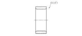
- FIG. 1 It is an enlarged photograph which shows the inner ring
- 2 is an enlarged photograph of each cross section of Example 1 and Comparative Example 1.
- FIG. It is the top view which looked at the outer ring from the track surface side. It is a model figure showing the contact of two objects. It is an iso-stress diagram under a contact surface.
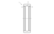
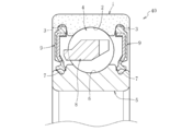
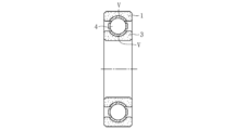
- FIG. 1 a shows a cross-sectional view of a rolling bearing race according to an embodiment of the present invention.
- the bearing ring shown in the figure is an outer ring 1 which is a constituent member of a single row ball bearing, and has an annular raceway surface 2 on which a ball as a rolling element rolls at a substantially central portion in the axial direction of the inner diameter surface thereof.
- annular seal mounting grooves 3 are formed as seal portions.
- a seal member 9 that seals a space between the inner peripheral surface of the outer ring 1 and the outer peripheral surface of the inner ring 5 is fixed to the seal attachment groove 3.
- the seal member 9 includes a member that comes into contact with the mating raceway (inner ring 5) and a member that does not contact the mating raceway.
- the outer ring 1 is formed of a sintered metal obtained by compressing a raw material powder to form a green compact, and sintering the green compact by heating at a sintering temperature or higher.
- the raceway surface 2 and the seal attachment groove 3 are plastic working surfaces formed by performing plastic working on the inner peripheral surface of the sintered metal material. At least the raceway surface 2 of the outer ring 1 is hardened by heat treatment.
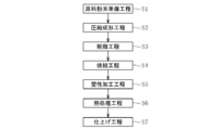
- the outer ring 1 is manufactured through a raw material powder preparation step S1, a compression molding step S2, a degreasing step S3, a sintering step S4, a plastic working step S5, a heat treatment step S6, and a finishing step S7 shown in FIG.
- a raw material powder is manufactured by mixing an iron-based low alloy powder, a carbon powder as a carbon solid solution source, and a molding lubricant responsible for lubrication during molding.
- Ni—Mo-based partially diffused alloy steel powder containing Ni and Mo as alloy components and the balance being Fe and inevitable impurities is used as the iron-based low alloy powder.
- the partial diffusion alloy steel powder used in this embodiment is obtained by diffusion-bonding Ni around the Fe—Mo alloy.
- the hardness of the alloy steel powder before sintering is higher than that of steel powder (pre-alloyed steel powder) in which Fe and Ni are completely alloyed by diffusing and attaching a metal such as Ni to the Fe alloy. Therefore, the moldability at the time of compression molding is ensured. As a result, a relatively large amount of Ni can be blended.
- the mixing ratio of Ni in the partial diffusion alloy steel powder of the present embodiment is 0.5 to 5.0 wt%, preferably 1.7 to 2.2 wt%.
- the mixing ratio of Mo in the partially diffused alloy steel powder is 0.5 to 3.0 wt%, preferably 0.8 to 1.1 wt%, and more preferably 0.9 to 1.1 wt%.
- the steel powder used as the base of the partially diffused alloy steel powder there are atomized powder, reduced powder, and the like. However, since the reduced powder has a porous particle and is difficult to increase in density, in this embodiment, pores are not formed. Solid atomized powder that does not have, especially water atomized powder is used in consideration of cost.
- the partial diffusion alloy steel powder the one in which Ni is diffusion-bonded around the Fe-Mo alloy is exemplified, but the alloy powder in which Ni or Mo is diffusion-bonded around the pure iron powder should be used. You can also.
- This partially diffused alloy steel powder is soft and has the same hardness as pure iron powder.
- a micro Vickers hardness of less than 120HV0.05, desirably less than 100HV0.05, more preferably less than 90HV0.05 is used.
- This hardness is lower than the particle hardness (approximately 120 HV 0.05 or more) in the Fe—Cr—Mo based complete alloy powder (pre-alloy powder) used in Patent Document 3. Therefore, compared to this type of complete alloy powder, it becomes easier to increase the density even with the same applied pressure.
- a partially diffused alloy steel powder having a maximum particle size of 500 ⁇ m or less (preferably 250 ⁇ m or less, more preferably 200 ⁇ m or less).
- This particle size can be obtained by sieving the obtained powder using a sieve having an upper limit particle size (for example, 500 ⁇ m).
- an upper limit particle size for example, 500 ⁇ m.
- the particle size may be increased by granulation in order to prevent a decrease in fluidity of the powder in the mold, but the partial diffusion alloy steel powder of this embodiment has a particle size of Is large and fluidity is good, so granulation is basically unnecessary.
- the carbon powder for example, artificial graphite powder is used.
- the graphite powder having a particle size D90 of 8 ⁇ m or less is used, preferably 6 ⁇ m or less, more preferably 4 ⁇ m or less.
- the graphite powder having a particle diameter D90 of 2 ⁇ m or more, preferably 3 ⁇ m or more is used.
- the blending ratio of the graphite powder is 0.35 wt% or less, preferably 0.3 wt% or less, more preferably 0.25 wt% or less with respect to the entire mixed powder. Further, the blending ratio of the graphite powder is 0.05 wt% or more, preferably 0.1 wt% or more, more preferably 0.15 wt% or more with respect to the whole mixed powder.
- carbon powder carbon black, ketjen black, nanocarbon powder and the like can be used in addition to the graphite powder. Two or more of these powders can be used.
- a known lubricant powder such as metal soap (for example, zinc stearate) or amide wax (for example, ethylene bisstearamide) can be arbitrarily selected and used.
- the type of lubricant powder is not limited as long as it is a component that does not remain in the raw material after sintering. Two or more types of molding lubricants can be used in combination.
- the powdery material 10 is molded by charging and filling the raw material powder into the cavity of the molding die and compressing it.
- the molding at this time is performed by a molding machine suitable for continuous production such as uniaxial and multiaxial pressure molding, CNC press molding, and the like.
- the green compact 10 formed in the compression molding step S2 is formed into a ring shape similar to the outer ring 1 shown in FIG. 1a, but both the inner diameter surface and the outer diameter surface are uneven. It is a smooth cylindrical surface with no surface.
- the molding lubricant is liquefied by the above-described high pressure, and the solid lubricant that has been liquefied diffuses and permeates between the raw material powders.
- the above molding pressure is only a guide.
- the density and pore size of the sintered body are important. Therefore, depending on the type of powder used and molding conditions, molding may be performed at a pressure lower than the above molding pressure. Absent.
- warm molding was used in which the mold and powder were heated to 60 ° C. or higher, or mold lubrication was used to reduce the amount of molding lubricant used.
- a molding machine can also be used.
- the molding lubricant contained in the green compact 10 is removed.
- Degreasing can be performed under the same conditions as those for producing a general sintered metal product.
- the degreased green compact 10 is heated at the sintering temperature or higher to form a sintered metal material 10 '.
- the sintering temperature is 1150 ° C. or higher and 1350 ° C. or lower, more preferably 1250 ° C. or higher and 1300 ° C. or lower so that a dense sintered metal material 10 ′ having small pores can be obtained.
- the sintered metal material 10 ′ after sintering has a relative density of 90% or more (preferably 95% or more, more preferably 97% or more).
- the raceway surface 2 and the seal mounting groove 3 are formed on the inner diameter surface of the sintered metal material 10 'by performing plastic working on the sintered metal material 10' formed as described above. Is done.
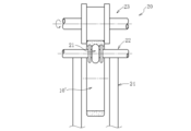
- These moldings can be simultaneously performed using, for example, a rolling machine (ring rolling machine) 20 as shown in FIG.
- the rolling machine 20 includes a shaft-shaped mandrel 22 having a mold portion 21 for forming the raceway surface 2 and the seal mounting groove 3 on the outer periphery, and a drive (not shown) in contact with the outer diameter surface of the sintered metal material 10 ′.
- a die roll 23 that rotates in response to the output of the source and a support roll 24 that supports the rotation of the mandrel 22 are provided.
- the raceway surface 2 and the two seal mounting grooves 3 may be molded separately or sequentially, as described above. Further, the raceway surface 2 and the seal mounting groove 3 may be formed so as to be accompanied by a reduction in the thickness and diameter of the metal sintered body 10 ′, or a reduction in the thickness and diameter of the metal sintered body 10 ′. You may go without accompanying.
- the plastic working method is not limited to rolling, and cold rolling processing in which the sintered metal material 10 ′ is rolled while rotating at room temperature, and burnishing processing can also be employed. Regardless of which plastic working method is employed, the accuracy of the raceway surface 2 and the seal mounting groove 3 and the surroundings thereof can be improved if the plastic working is carried out cold compared to the case where the plastic working is carried out warm or hot. The density can be increased efficiently.
- a process for example, shot peening
- hard particles are projected onto a necessary portion such as the raceway surface 2 and the holes near the surface layer are clogged with the energy.
- the sintered metal material 10 ′ in which the raceway surface 2 and the seal mounting groove 3 are formed is quenched and tempered to harden at least the raceway surface 2 of the sintered metal material 10 ′ and thereby the raceway surface.
- 2 is a process of ensuring the rolling fatigue life required for 2.
- various quenching treatments or surface hardening treatments
- carburizing, carbonitriding, and induction quenching can be employed in addition to continuous quenching.
- the finishing step S7 is a finishing process such as grinding, polishing, lapping, super-finishing, etc., on a predetermined portion (for example, the raceway surface 2 or the seal mounting groove 3) of the sintered metal body 10 ′ that has undergone the heat treatment step S6. Is a step of further improving the accuracy of a predetermined portion of the sintered metal body 10 ′ by applying one or more of the above.
- the finishing step S7 may be performed as necessary, and is not necessarily performed. Even if the finishing process is executed in the finishing step S7, the amount of processing (processing time) is extremely small, and therefore the influence on the yield and the number of processing steps is very small.
- the outer ring 1 manufactured through the above steps has a high density, it is possible to obtain the same mechanical strength as the outer ring 1 made of melted material. Further, since the raceway is made of sintered metal and the raceway surface 2 and the seal attachment groove 3 are formed by plastic working, it can be formed into a near net shape and the material yield is improved. Therefore, it is possible to reduce the cost of the rolling bearing.
- FIG. 5 shows a single row ball bearing 40 which is a kind of rolling bearing.
- a ball bearing 40 shown in FIG. 1 includes an outer ring 1 having an annular raceway surface 2 on an inner diameter surface, an inner ring 5 having an annular raceway surface 6 on an outer diameter surface, and both raceway surfaces 2 and 6.
- the inner diameter end of each seal member 9 is in contact with a seal groove 7 provided on the outer peripheral surface of the inner ring 5 to constitute a contact seal.
- the outer diameter end of the seal member 9 is press-fitted and fixed in the seal attachment groove 3 of the outer ring 1.
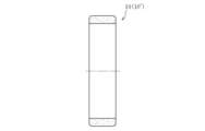
- the cylindrical green compact 15 shown in FIG. 4b is manufactured through the raw material powder preparation step S1 and the compression molding step S2 in the same manner as described above, and then the sintered metal material through the degreasing step S3 and the sintering step S4. 15 'is produced. Thereafter, in the plastic working step S5, the raceway surface 6 and the seal groove 7 as a seal portion are formed. Thereafter, through the heat treatment step S6 and the finishing step S7, the inner ring 5 shown in FIG. 4a is completed.
- FIG. 5 illustrates a single-row ball bearing as the rolling bearing, but other types of rolling bearings such as a cylindrical roller bearing, a tapered roller bearing, a needle roller bearing, an angular ball bearing, and the like are also included.
- the manufacturing procedure described above can also be applied to the manufacturing process of the raceway.
- the above manufacturing procedure can be applied not only to single-row type rolling bearing raceways but also to double-row rolling bearing raceways and thrust rolling bearing raceways having thrust raceway surfaces.
- the above manufacturing procedure can be applied to a bearing ring in which the seal mounting groove 3 and the seal groove are omitted, and also to a rolling bearing without the seal member 9.
- the raceway surface 2 (including the seal attachment groove 3) is plastically processed as in the above-described manufacturing procedure, the pressure applied during the plastic working is hardly exerted at least around the raceway surface 2 of the sintered metal material 10 ′.
- the porous structure can be further densified (densified) compared to the region, for example, the central portion in the thickness direction of the sintered metal material 10 ′. If the periphery of the raceway surface 2 is densely formed, the number of rough atmospheric holes that become a stress concentration source is reduced, and separation of the raceway surface 2 and the like from the origin is less likely to occur. It can be further improved.
- the relative density of the sintered metal material 10 ′ is represented by the following formula (1).
- the true density [g / cm 3 ] in the formula (1) means a theoretical density of a material that does not have pores inside the raw material, such as a melted material, and can be obtained in detail from the following formula (2). it can.
- the relative density is an effective measure for evaluating the degree of densification of the entire raceway, it is not necessarily effective for evaluating the presence or absence of rough atmospheric pores in a region limited to the periphery of the raceway surface.
- the relative density of the entire raceway exceeds the lower limit value, there are cases where there are coarse air holes in the vicinity of the raceway surface, but there are cases where coarse air holes exist, and this coarse air hole is expected to be the starting point of separation.
- it is conceivable to define a relative density limited to the periphery of the raceway surface it is not easy to strictly measure the relative density of a part of the raceway.
- the region to be densified by plastic working should be originally determined according to the load (surface pressure) applied to the raceway surface 2.
- the envelope of the largest hole estimated to be present in at least the critical volume of the bearing ring (generally a depth at which stress of 90% or more of the maximum shear stress is applied).
- the dangerous volume means the volume of the part that has a risk of causing the separation of the raceway surface
- Dangerous volume (contact ellipse major axis) x (circumferential surface length in the circumferential direction) x (depth at which 90% of the maximum shear stress acts) It is represented by
- the depth of the maximum shear stress ⁇ 45 (maximum shear stress acting at an angle of 45 ° with respect to the surface) can be calculated by the method described below.
- the object 1 is considered as an inner ring and the object 2 is considered as a ball (sphere).
- the sum ⁇ of the principal curvature ⁇ of the contact object is It is represented by The principal curvature ⁇ is the reciprocal of the radius, and has a positive sign on the convex surface and a negative sign on the concave surface.
- the auxiliary variable cos ⁇ used in the subsequent calculations is It is.
- ⁇ Hertzian contact coefficient
- ⁇ Poisson's ratio
- ⁇ oil kinematic viscosity
- the auxiliary variable cos ⁇ , the Hertzian contact coefficient and ⁇ , and the kinematic viscosity ⁇ of the oil can also be calculated from the following equations using the complete elliptic integral as a medium.
- K and E are first-type and second-type complete elliptic integrals, which are values represented by the following equations.
- K and E can be obtained from the numerical table.
- the maximum value of the hole envelope area is estimated using extreme value statistics. Specifically, the square root ⁇ area max of the estimated maximum hole envelope area is calculated through the following procedure.
- the specimen subjected to the mirror polishing is observed with a microscope, and an image of the y region having the defined reference area S 0 (mm 2 ) is acquired.
- the obtained image is binarized using image analysis software, and the envelope area of the holes is analyzed.
- the largest envelope area obtained is defined as the maximum hole envelope area in the reference area S 0 (mm 2 ), and its square root is defined as ⁇ area max in that region. This measurement is repeated n times while changing the inspection region.
- ⁇ area max is taken on the coordinate horizontal axis of the extreme value probability sheet, and the above result is plotted to obtain an extreme value distribution (the vertical axis of the extreme value probability sheet takes F or y).
- An approximate straight line obtained by the least square method is extrapolated with respect to the extreme value distribution to obtain a and b represented by Expression 16.
- y is the normalization variable represented by Formula 17
- T is the recursion period represented by Formula 18
- V is the volume (mm 3 ) of the estimation target region
- V 0 is the reference volume (mm) represented by Formula 19. 3 )
- h is an average value (mm) of the measured ⁇ area max, j represented by Equation 20.
- the powders were filled in dies of outer diameter ⁇ 48 mm ⁇ inner diameter ⁇ 34 mm and outer diameter ⁇ 32 mm ⁇ inner diameter ⁇ 16 mm, uniaxially pressed, and then sintered at 1250 ° C. for 150 minutes in an inert gas atmosphere consisting of nitrogen and hydrogen.
- a ring-shaped sintered metal material having a density of 7.5 g / cm 3 was obtained.
- the former is a sintered metal material for the outer ring and the latter is an inner ring.
- the density measurement result is based on the Archimedes method.
- the dimensional variation between the test pieces was made uniform within a predetermined region by passing through a dimensional correction process called sizing. .
- the plastic processed product is carburized at 880 ° C., heated to 840 ° C., quenched, tempered at 180 ° C., and then subjected to a finishing process by polishing, whereby an outer ring having an outer diameter of ⁇ 62 mm ⁇ inner diameter of ⁇ 52.1 mm
- an inner ring having an outer diameter of ⁇ 40 mm ⁇ an inner diameter of ⁇ 30 mm was obtained (hereinafter, the inner and outer rings are referred to as “Example 1”).
- the inner and outer rings conform to JIS standard 6206 model bearing inner and outer rings.
- Comparative Example 1 a complete alloy powder containing 1.5 wt% of Cr, 0.2 wt% of Mo, 0.3 wt% of carbon (C), and the balance being iron, is the same as in Example 1.
- the inner and outer rings were produced by the manufacturing method (Comparative Example 1). This is a test piece meeting the conditions described in Patent Document 3, and the sintered density before plastic working is 6.8 g / cm 3 (relative density of about 87%).
- Example 2 For comparison, after molding and sintering in the same manner as in Example 1, the inner and outer rings were formed into a raceway shape by turning rather than plastic working, and carburized and heat-treated and finished as in Example 1 (Comparative Example). 2) and inner and outer rings of 6206 model bearings made of molten material (material: SUJ2, heat treatment: submerged quenching and tempering, open type without seal, C3 gap) were prepared (Comparative Example 3).
- Test method The test conditions for the rolling fatigue life test were a maximum contact surface pressure Pmax of 3.2 GPa and a bearing rotational speed of 3000 rpm. Turbine oil VG56 was used as the lubricating oil, and this clean oil was circulated through the bearing during the test. By monitoring the vibration of the bearing during operation with the vibration detector, damage such as separation occurs in the inner and outer rings of the bearing, and the test is stopped when the vibration of the bearing exceeds the specified value. Was recorded as the life of the bearing. In addition, after the test was stopped, the bearings were disassembled and the inner and outer rings were checked for damage.
- the predicted volume V is a region extending from the entire raceway surface to a depth of about 0.21 mm (rotating body obtained by rotating the hatched portion V in FIG. 6 once), 350 mm 3 for the outer ring 1, and 3 for the inner ring 3. In was 250mm 3.
- the numerical predictions volume to evaluate a more secure side, the actual risk volume (in the outer ring about 320 mm 3, the inner ring about 210 mm 3) are slightly larger than.
- Example 1 From comparison between Example 1 shown in FIG. 9 and Comparative Examples 1 and 2, it is clear that the smaller the estimated value of the square root ⁇ area max of the maximum hole envelope area, the longer the rolling fatigue life of the bearing ring. became. If this estimated value is less than 50 ⁇ m, it will not be as good as the bearing using the inner and outer rings made of SUJ2 in Comparative Example 3, but it will show a life of about 70 to 80% of the L 10 life of the bearing. Became clear. From this, it is considered that Example 1 may be able to replace the melted material bearing (Comparative Example 3) depending on the use environment and conditions.
- Example 1 the form of damage (flaking) when the rolling fatigue life is reached is considered to be internal starting type separation of the inner ring or the outer ring as in the case of the melted material bearings including SUJ2.
- FIG. 7 b shows a photograph of the inner ring where peeling occurred before and after the test
- FIG. 8 b shows an enlarged photograph of the peeling portion. 7a and 8a are both before the test.
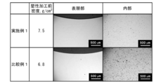
- FIG. 10 shows a representative example of the observation results of the surface layer and the inside (unplastic working region) of the outer ring of Example 1 and Comparative Example 1.
- Example 1 since the density was increased to 7.5 g / cm 3 (relative density of about 96%) before the plastic working, the square root of the estimated maximum envelope area ⁇ There are no coarse pores with an area max exceeding 50 ⁇ m. Since the region where plastic working does not reach is such a dense structure, there are no coarse pores exceeding 50 ⁇ m in the surface layer portion subjected to plastic working (particularly, the region shallower than the depth corresponding to the dangerous volume). Further, in the surface layer portion, no vacancies with a square root of the estimated maximum envelope area exceeding 20 ⁇ m were observed.
- the square root ⁇ area max of the envelope area of the largest hole estimated to exist at least in the predicted volume is less than 50 ⁇ m (preferably less than 40 ⁇ m, more preferably 30 ⁇ m) with the dangerous volume of the raceway as the predicted volume. Therefore, there are no coarse holes around the raceway surface. Therefore, it is possible to prevent the raceway from being damaged, such as peeling, starting from the coarse holes, and to obtain a rolling fatigue life comparable to that of the melted material.
- Fe—Ni—Mo based partially diffused alloy steel is used, but this powder is as soft as pure iron powder as already described. Therefore, the density can be increased at the time of compression molding, and the generation of rough air holes around the raceway surface can be avoided by the synergistic effect of this and densification by plastic working. In addition, the formability when the raceway surface 2 and the like are formed by plastic working is also good. Furthermore, since this powder is easy to obtain and low in cost, it is possible to reduce the cost of the bearing ring and, in turn, the rolling bearing.
- Patent Document 3 also describes the use of stainless steel powder such as SUS420 and bearing steel powder such as SUJ2 in addition to the Fe—Cr—Mo alloy powder of Comparative Example 1. Since the powder contains a large amount of Cr, the same problem as in Comparative Example 1 occurs.
- the numerical value of the predicted volume is slightly larger than the actual dangerous volume, and the region including the entire axial direction of the raceway surface is set as the predicted volume V. (See FIG. 6). This is because the safety is evaluated in consideration of the axial load acting on the bearing. If the critical volume corresponding to the axial width (major axis) of the contact ellipse is the predicted volume V, and at least the plane direction of the maximum hole envelope area within this predicted volume is less than 50 ⁇ m, the rolling fatigue life of the raceway is improved. Can be made.
- the case where the estimated volume V is determined based on the dangerous volume and the square root ⁇ area max of the maximum hole envelope area is estimated is illustrated, but in addition to this, as shown in FIG.
- the square root ⁇ area of the maximum hole envelope area It is also possible to estimate max .
Landscapes
- Engineering & Computer Science (AREA)
- Chemical & Material Sciences (AREA)
- Mechanical Engineering (AREA)
- General Engineering & Computer Science (AREA)
- Materials Engineering (AREA)
- Metallurgy (AREA)
- Organic Chemistry (AREA)
- Manufacturing & Machinery (AREA)
- Crystallography & Structural Chemistry (AREA)
- Thermal Sciences (AREA)
- Physics & Mathematics (AREA)
- Rolling Contact Bearings (AREA)
- Powder Metallurgy (AREA)
- Sealing Of Bearings (AREA)
Abstract
部分拡散合金鋼粉を圧縮成形した後、焼結することにより焼結金属素材10'を形成し、焼結金属素材10'に塑性加工で軌道面2を形成して軌道輪1を製作する。軌道輪1の少なくとも危険体積を予測体積として、少なくともこの予測体積に存在すると推定される最大空孔の包絡面積の平方根√areamaxを50μm未満に設定する。これにより、低コストでありながら、転がり疲労寿命を向上させた転がり軸受用軌道輪を提供する。
Description
本発明は、軌道輪および該軌道輪を有する転がり軸受に関する。
転がり軸受の構成部材である軌道輪(例えば内輪や外輪)は、ボールやころ等の転動体が転動する軌道面を有している。この種の軌道輪は、中実の金属素材(溶製材)に切削等の機械加工あるいは鍛造等の塑性加工を施すことで略完成品形状の中間加工品を得る工程、中間加工品に焼入れ等の熱処理を施す熱処理工程、および特に高精度が要求される部位に研削、研磨等の仕上げ加工を施す仕上げ工程などを経て最終製品に仕上げられるのが一般的である。
既存の軌道輪の製造方法において、中間加工品を得るために機械加工を選択した場合、高精度の中間加工品を得ることができるという利点はあるが、加工量が多く材料ロスが大きいために歩留の向上を図る上で難がある。また、加工量が多く、加工工具を頻繁に交換する必要があるためにダウンタイムが長くなり易く、生産効率を有効に高め得ないという問題もある。これらの問題は、軌道輪が複雑形状を呈する場合ほどその傾向が大きくなる。一方、中間加工品を得るために塑性加工を選択すると、中間加工品の製作段階における材料ロスを少なくすることができるという利点はあるが、機械加工ほどの加工精度を確保することが難しいために入念かつ大幅な仕上げ加工が必要となる。そのため、仕上げ加工に手間とコストを要し、また、期待するほどの材料ロスの軽減効果を得られないのが実情である。
このように、溶製材から軌道輪を得るようにした場合、上述した各理由から、軌道輪、ひいては転がり軸受の低コスト化に限界が生じる。そこで、例えば下記の特許文献1~3に記載されているように、軌道輪としての内輪又は外輪を焼結金属(金属焼結体)で形成する提案がなされている。
特許文献1には、ガスアトマイズした高速度工具鋼粉をCIP法(冷間等方圧加圧法)+熱間押出法、もしくはHIP法(熱間等方圧加圧法)で焼結することで、最大空孔の真円換算直径が3μm以下で、最大炭化物の真円換算直径が12μm以下であり、かつ硬さがHRC64を超え69未満の軌道輪や転動体を製作する旨が開示されている。
特許文献2には、ガスアトマイズした、クロムを多く含む所定組成の鋼粉末をHIP法で焼結した軸受部品が開示されている。
特許文献3には、焼結体に塑性加工で軌道面を形成することで、相対密度を80%以上100%未満にした軸受用軌道輪が開示されている。
特許文献2には、ガスアトマイズした、クロムを多く含む所定組成の鋼粉末をHIP法で焼結した軸受部品が開示されている。
特許文献3には、焼結体に塑性加工で軌道面を形成することで、相対密度を80%以上100%未満にした軸受用軌道輪が開示されている。
しかしながら、特許文献1で使用される高速度工具鋼粉末は、クロム、タングステン、モリブデン、バナジウム等を多く含む鋼粉末であるため、高価である。特許文献2で使用される粉末も入手困難な特殊粉末であり、同様の問題を生じる。また、何れの粉末もガスアトマイズされた完全合金鋼粉であるために圧縮性が低い。従って、高密度化するためにHIPやCIP等の量産性の低い焼結工程を用いざるを得ない。以上から、特許文献1および2に開示された軌道輪や転がり軸受では、製造コストが高騰する問題がある。
また、特許文献3では、機械的強度確保のために軌道輪の相対密度を向上させる旨が記載されているが、軌道輪全体が高密度でも、軌道面付近に粗大気孔を生じる可能性がある。その場合、この粗大気孔が起点となって軌道面の剥離等を生じるおそれがあり、軌道輪の転動疲労寿命が不十分となる。
そこで、本発明は、低コストでありながら、転がり疲労寿命を向上させた転がり軸受用軌道輪および該軌道輪を用いた転がり軸受を提供することを目的とする。
本発明にかかる軸受用軌道輪は、転動体が転動する軌道面を有し、前記軌道面が焼結金属素材に塑性加工を施すことで形成されているものであって、前記焼結金属素材が、部分拡散合金鋼粉を圧縮成形した後、焼結することにより形成され、危険体積を予測体積として、該予測体積に存在すると推定される最大空孔の包絡面積の平方根√areamaxが50μm未満(好ましくは40μm未満、より好ましくは30μm未満)であることを特徴とするものである。
また、本発明にかかる軸受用軌道輪は、転動体が転動する軌道面を有し、前記軌道面が焼結金属素材に塑性加工を施すことで形成されているものであって、前記焼結金属素材が、部分拡散合金鋼粉を圧縮成形した後、焼結することにより形成され、軌道面に生じる接触楕円の軸方向幅の範囲で最大せん断応力を生じる深さに至るまでの領域を予測体積として、該予測体積に存在すると推定される最大空孔の包絡面積の平方根√areamaxが50μm未満(好ましくは40μm未満、より好ましくは30μm未満)であることを特徴とするものである。
これらの構成により、軌道面周辺の焼結組織に粗大空孔が存在しなくなるので、この粗大空孔を起点として軌道輪にフレーキング等の損傷が生じるのを防止することができ、溶製材に匹敵する転動疲労寿命を得ることが可能となる。
また、部分拡散合金鋼粉としてFe-Ni-Mo系を使用すれば、この粉末が軟らかいため、圧縮成形時に高密度化することができる。従って、塑性加工による緻密化の作用と併せて、軌道面周辺での粗大気孔の発生を回避することができる。また、軌道面等を塑性加工で成形する際の成形性も良好なものとなる。
また、部分拡散合金鋼粉として、水アトマイズされた鋼粉もしくは純鉄粉に合金成分を拡散接合させたものを使用すれば、軌道輪、延いては転がり軸受の低コスト化を図ることができる。
本発明によれば、低コストでありながら、転がり疲労寿命を向上させた軌道輪を提供することができる。従って、この軌道輪を転がり軸受の構成部品として用いることで、転がり軸受の低コスト化を図ることができる。
以下、本発明の実施の形態を図面に基づいて説明する。
図1aに、本発明の一実施形態に係る転がり軸受用軌道輪の断面図を示す。同図に示す軌道輪は単列の玉軸受の構成部材である外輪1であり、その内径面の軸方向略中央部に、転動体としてのボールが転動する環状の軌道面2を有する。軌道面2の軸方向両側には、シール部として環状のシール取り付け溝3が形成されている。シール取り付け溝3には、図5に示すように、外輪1の内周面と内輪5の外周面との間の空間をシールするシール部材9が固定される。シール部材9としては、同図に示すように相手側の軌道輪(内輪5)に接触するものの他、相手側の軌道輪に対して非接触となるものも含まれる。
この外輪1は、原料粉末を圧縮成形して圧粉体を形成し、この圧粉体を焼結温度以上で加熱することによって焼結させた焼結金属で形成される。この実施形態において、軌道面2およびシール取り付け溝3は、焼結金属素材の内周面に塑性加工を施すことによって成形された塑性加工面である。外輪1の少なくとも軌道面2は、熱処理により硬化されている。
この外輪1は、図2に示す原料粉末準備工程S1、圧縮成形工程S2、脱脂工程S3、焼結工程S4、塑性加工工程S5、熱処理工程S6、および仕上げ工程S7を経て製造される。
原料粉末準備工程S1では、鉄系低合金粉末と、炭素固溶源としての炭素粉末と、成形時の潤滑を担う成形用潤滑剤とを混合して原料粉末が製造される。
鉄系低合金粉末としては、合金成分としてNiおよびMoを含み、残部をFe及び不可避的不純物としたNi-Mo系の部分拡散合金鋼粉が使用される。この実施形態で使用する部分拡散合金鋼粉は、Fe-Mo合金の周囲にNiを拡散接合させたものである。このように、Fe合金にNi等の金属を拡散付着させることで、FeとNiとを完全に合金化した鋼粉(プレアロイ鋼粉)と比べて、焼結前の合金鋼粉の硬さが抑えられるため、圧縮成形時の成形性が確保される。その結果、比較的多量のNiを配合することが可能となる。具体的に、本実施形態の部分拡散合金鋼粉におけるNiの配合割合は、0.5~5.0wt%、好ましくは1.7~2.2wt%とされる。一方、Moは、多量に添加してもその効果は飽和して、かえって成形性を悪化させる原因となる。このため、部分拡散合金鋼粉におけるMoの配合割合は、0.5~3.0wt%、好ましくは0.8~1.1wt%、より好ましくは0.9~1.1wt%とされる。
部分拡散合金鋼粉のベースとなる鋼粉としては、アトマイズ粉や還元粉等が存在するが、還元粉は粒子が多孔質で高密度化が困難であるため、本実施形態では、空孔を有しない中実のアトマイズ粉、特にコスト面も考えて水アトマイズ粉を使用する。なお、部分拡散合金鋼粉の例として、Fe-Mo合金の周囲にNiを拡散接合させたものを例示したが、純鉄粉の周囲にNiやMoを拡散接合させた合金粉を使用することもできる。
この部分拡散合金鋼粉は軟質であり、純鉄粉と同程度の硬さを有する。部分拡散合金鋼粉の硬さの目安として、マイクロビッカース硬度で120HV0.05未満、望ましくは100HV0.05未満、より好ましくは90HV0.05未満のものが使用される。この硬度は、特許文献3で使用される、Fe-Cr-Mo系の完全合金粉末(プレアロイ粉末)における粒子の硬さ(概ね120HV0.05以上)に比べて低い。そのため、この種の完全合金粉末に比べ、同一の加圧力でもより高密度化させやすくなる。
この部分拡散合金鋼粉としては、粒径が最大で500μm以下(好ましくは250μm以下、より好ましくは200μm以下)のものを使用するのが望ましい。この粒径は、目開きが上限粒径(例えば500μm)である篩を使用して、入手した粉末を篩分けすることで得ることができる。500μmを越える粗大粉末が含まれていると、後述の圧縮成形工程S2での充填性が悪化し、焼結組織中に粗大空孔が発生し易くなる。微細な粒子径を有する合金鋼粉では、金型での粉末の流動性低下を防止するため、造粒により粒径を大きくする場合があるが、本実施形態の部分拡散合金鋼粉は粒子径が大きく、流動性も良好であるので、造粒は基本的に不要である。
炭素粉末としては、例えば人造黒鉛の粉末が使用される。黒鉛粉末は、粒径D90が8μm以下のものが使用され、好ましくは6μm以下、より好ましくは4μm以下のものが使用される。また、黒鉛粉末の粒径D90は、2μm以上、好ましくは3μm以上のものが使用される。黒鉛粉末の配合割合は、混合粉末全体に対して0.35wt%以下、好ましくは0.3wt%以下、より好ましくは0.25wt%以下とされる。また、黒鉛粉末の配合割合は、混合粉末全体に対して0.05wt%以上、好ましくは0.1wt%以上、より好ましくは0.15wt%以上とされる。炭素粉末としては、黒鉛粉末の他、カーボンブラック、ケッチェンブラック、ナノカーボン粉末などを使用することもできる。これらの何れかの粉末を二種以上使用することも可能である。
成形用潤滑剤としては、金属石けん(例えばステアリン酸亜鉛)やアミドワックス(例えばエチレンビスステアルアミド)等の公知の潤滑剤粉末を任意に選択して使用することができる。本発明の目的を果たす上では、焼結後に素材内部に残存しない成分であれば潤滑剤粉末の種類は問わない。また、二種類以上の成形用潤滑剤を併用することもできる。
圧縮成形工程S2では、成形金型のキャビティに上記の原料粉末を投入・充填し、これを圧縮することで圧粉体10を成形する。この時の成形は、一軸および多軸加圧成形、CNCプレス成形などの連続生産に適した成形機で行われる。図1bに示すように、圧縮成形工程S2にて成形される圧粉体10は、図1aに示す外輪1と同様のリング状に成形されるが、その内径面および外径面の双方は凹凸のない平滑な円筒面とされている。
圧縮成形工程S2での成形圧力は588MPa(6tf/cm2)以上、より好ましくは980MPa(10tf/cm2)以上とする。圧粉体10の成形時には、上記の高い加圧力により成形用潤滑剤が液相化し、この液相化された固体潤滑剤が原料粉末相互間に拡散・浸透する。但し、上記の成形圧力は目安にすぎない。本発明の目的を達成するためには、焼結体の密度や空孔サイズが重要となるので、使用する粉末の種類や成形条件によっては、上記成形圧力よりも低い圧力で成形しても構わない。また、さらなる高密度化のために金型および粉末を60℃以上に加温して成形する温間成形を採用し、あるいは成形用潤滑剤の使用量を削減するために金型潤滑を用いた成形機を使用することもできる。
脱脂工程S3では、圧粉体10に含まれる成形用潤滑剤が除去される。脱脂は、一般的な焼結金属製品を製作する場合と同様の条件で行うことができる。
焼結工程S4では、脱脂された圧粉体10を焼結温度以上で加熱し、焼結金属素材10’を形成する。緻密で空孔の小さい焼結金属素材10’が得られるように、焼結温度は1150℃以上1350℃以下、より好ましくは1250℃以上1300℃以下とする。また、酸化による焼結性および強度の低下と、脱炭とを防止するため、窒素、水素、アルゴン等を主成分とする不活性もしくは還元性雰囲気下で焼結するのが好ましい。なお、真空下で焼結することもできる。焼結後の焼結金属素材10’は、相対密度90%以上(好ましくは95%以上、より好ましくは97%以上)を有する。
塑性加工工程S5では、上記のようにして形成された焼結金属素材10’に対して塑性加工を施すことにより、焼結金属素材10’の内径面に軌道面2およびシール取り付け溝3が成形される。これらの成形は、例えば図3に示すような転造機(リング転造機)20を用いて同時に行うことができる。転造機20は、軌道面2およびシール取り付け溝3を成形するための型部21を外周に有する軸状のマンドレル22と、焼結金属素材10’外径面に接した状態で図示外の駆動源の出力を受けて回転するダイロール23と、マンドレル22の回転を支持するサポートロール24とを備えている。このような転造機20において、焼結金属素材10’の内周に挿通したマンドレル22をサポートロールで支持しつつ、焼結金属素材10’の内外径面をマンドレル22とダイロール23とで挟み込み、ダイロール23をサポートロール24側に押し付けつつ回転させる。これにより、焼結金属素材10’の内径面に軌道面2およびシール取り付け溝3が成形される。
軌道面2と二つのシール取り付け溝3は、上記のように同時成形する他、個別に順次成形しても構わない。また、軌道面2とシール取り付け溝3の成形は、金属焼結体10’の薄肉化および大径化を伴うように行っても良いし、金属焼結体10’の薄肉化および大径化を伴わないように行っても良い。塑性加工法は、転造に限らず、常温下で焼結金属素材10’を回転させながら圧延する冷間ローリング加工、さらにはバニシング加工等を採用することもできる。何れの塑性加工法を採用する場合でも、冷間で塑性加工を行えば、温間あるいは熱間で塑性加工を行う場合に比べ、軌道面2やシール取り付け溝3の精度およびそれらの周辺での密度を効率的に高めることができる。
また、軌道面2等の塑性加工後に、軌道面2をはじめとする必要部位に硬質粒子を投射し、そのエネルギーで表層近傍の空孔を目潰しする加工(例えばショットピーニング)を施してもよい。
熱処理工程S6は、軌道面2およびシール取り付け溝3が成形された焼結金属素材10’に焼入れおよび焼き戻しを行うことにより、焼結金属素材10’の少なくとも軌道面2を硬化させて軌道面2に必要とされる転動疲労寿命を確保する工程である。焼入れの手法としては、ずぶ焼入れの他、浸炭、浸炭窒化、高周波焼入れ等の各種焼入れ処理(もしくは表面硬化処理)を採用することができる。焼入れ後に焼き戻しを行うことで、焼結金属素材内部の靭性が確保されるため、き裂の進展が抑制される。
仕上げ工程S7は、熱処理工程S6を経た金属焼結体10’の所定部位(例えば、軌道面2やシール取り付け溝3)に対して研削加工、研磨加工、ラップ加工、超仕上げ加工等の仕上げ処理を一又は複数種施すことにより、金属焼結体10’の所定部位の精度を一層高める工程である。この仕上げ工程S7は、必要に応じて実行すれば足り、必ずしも実行する必要はない。なお、この仕上げ工程S7で仕上げ処理を実行するにしても、その加工量(加工時間)は極めて少なく、従って歩留や加工工数に及ぼす影響は極めて軽微である。
以上の工程を経て製作した外輪1は高密度であるので、溶製材からなる外輪1と同程度の機械的強度を得ることができる。また、軌道輪を焼結金属製とし、さらに塑性加工によって軌道面2およびシール取り付け溝3を成形しているため、ニヤネットシェイプ化が可能で、材料歩留りが良好となる。そのため、転がり軸受の低コスト化を図ることができる。
次に転がり軸受の構成を説明する。
図5は、転がり軸受の一種である単列の玉軸受40を示すものである。同図に示す玉軸受40は、内径面に環状の軌道面2が設けられた外輪1と、外径面に環状の軌道面6が設けられた内輪5と、両軌道面2,6の間に配された転動体としての複数のボール4と、ボール4を円周方向所定間隔で保持する保持器8と、ボール4の軸方向両側に配設されたシール部材9とを備えている。各シール部材9の内径端部は、内輪5の外周面に設けられたシール溝7と接触して接触シールを構成している。シール部材9の外径端部は外輪1のシール取り付け溝3に圧入固定されている。
図5は、転がり軸受の一種である単列の玉軸受40を示すものである。同図に示す玉軸受40は、内径面に環状の軌道面2が設けられた外輪1と、外径面に環状の軌道面6が設けられた内輪5と、両軌道面2,6の間に配された転動体としての複数のボール4と、ボール4を円周方向所定間隔で保持する保持器8と、ボール4の軸方向両側に配設されたシール部材9とを備えている。各シール部材9の内径端部は、内輪5の外周面に設けられたシール溝7と接触して接触シールを構成している。シール部材9の外径端部は外輪1のシール取り付け溝3に圧入固定されている。
図5に示す玉軸受の外輪1のみならず、内輪5も上記の製造手順で製造することができる。この場合、上記と同様に原料粉末準備工程S1および圧縮成形工程S2を経て図4bに示す円筒状の圧粉体15が製作され、次いで、脱脂工程S3および焼結工程S4を経て焼結金属素材15’が製作される。その後、塑性加工工程S5で軌道面6およびシール部としてのシール溝7が成形される。その後、熱処理工程S6、および仕上げ工程S7を経ることで、図4aに示す内輪5が完成する。
図5では、転がり軸受として単列の玉軸受を例示しているが、これ以外にも、円筒ころ軸受、円すいころ軸受、針状ころ軸受、アンギュラ玉軸受等のような他のタイプの転がり軸受における軌道輪の製造工程にも上記の製造手順を適用することができる。もちろん、単列タイプの転がり軸受用軌道輪のみならず、複列タイプの転がり軸受用軌道輪や、スラスト軌道面を有するスラスト転がり軸受の軌道輪にも上記の製造手順を適用することができる。また、軸受用途によっては、シール取付け溝3やシール溝を省略した軌道輪、さらにはシール部材9を有しない転がり軸受にも上記の製造手順を適用することができる。
ところで、上記の製造手順のように、軌道面2(シール取り付け溝3も含む)を塑性加工すれば、焼結金属素材10’の少なくとも軌道面2周辺では、塑性加工時の加圧力がおよびにくい領域、例えば焼結金属素材10’の厚み方向の中央部に比べて多孔質組織を一層緻密化(高密度化)することができる。軌道面2の周辺が緻密に形成されれば、応力集中源となる粗大気孔が少なくなり、それを起点とした軌道面2の剥離等も発生し難くなることから、軌道輪の繰り返し疲労強度をさらに向上させることができると考えられる。
このように軌道面周辺の粗大気孔の有無は軌道輪の耐久寿命に大きな影響を与えると考えられるため、軌道輪の耐久寿命を評価するためには、粗大気孔の存在の程度を何らかの形で数値化することが望まれる。数値化する一つの手段として、特許文献3に記載のように、焼結金属素材10’の相対密度を規定することが考えられる。ここで、相対密度は以下に示す式(1)で表されるものである。

なお、式(1)における真密度[g/cm3]は溶製材のように素材内部に空孔が存在しない材料の理論密度を意味し、詳細には下記の式(2)から求めることができる。

例えば、Fe、Crの化学成分が87.0、13.0[wt%]であるステンレス材の真密度は、上記各元素の密度がそれぞれ7.87、7.15[g/cm3]であることから、下記の式(3)のとおりとなる。

しかしながら、相対密度は軌道輪全体の緻密化の程度を評価する上では有効な尺度であるにしても、軌道面周辺に限った領域での粗大気孔の有無を評価する上では必ずしも有効ではない。例えば、軌道輪全体の相対密度が下限値を超えていても、軌道面周辺に数は少ないながらも粗大気孔が存在する場合があり、この粗大気孔が剥離の起点となることが予想される。軌道輪のうち、軌道面周辺に限った相対密度を規定することも考えられるが、そのような軌道輪の一部領域の相対密度を厳密に測定することは容易ではない。また、塑性加工により緻密化されるべき領域は、本来、軌道面2に負荷される荷重(面圧)に応じて決定すべきである。
以上の検証に基づき、本発明では、軌道輪のうち、少なくとも軌道輪の危険体積(一般に最大せん断応力の90%以上の応力が掛かる深さ)の領域に内在すると推定される最大空孔の包絡面積の平方根√areamax[(areamax)1/2]に着目した。
ここで、危険体積は、軌道面の剥離を生じる危険性のある部分の体積を意味し、
危険体積=(接触楕円長径)×(軌道面の円周方向長さ)×(最大せん断応力の90%が作用する深さ)
で表される。
危険体積=(接触楕円長径)×(軌道面の円周方向長さ)×(最大せん断応力の90%が作用する深さ)
で表される。
また、最大せん断応力τ45(表面に対して45°傾いて作用する最大せん断応力)の深さは、以下に述べる手法で計算することができる。
例えば、溶製材製6206型番の転がり軸受(材質:SUJ2、ヤング率21200kgf/mm2、ポアソン比:0.33)の内輪の場合を記述する。
・球の直径 :9.525mm → 半径4.7625mm
・球数 :8ケ
・内輪溝径 :9.716mm → 半径4.858mm
・内輪溝底径:36.975mm → 半径18.4875mm
・球の直径 :9.525mm → 半径4.7625mm
・球数 :8ケ
・内輪溝径 :9.716mm → 半径4.858mm
・内輪溝底径:36.975mm → 半径18.4875mm
図12に記載の二物体の接触を考え、以下、物体1を内輪、物体2をボール(球)として考える。
接触物体の主曲率ρの総和Σρは、

で表される。
なお、主曲率ρは半径の逆数であり、凸面では正、凹面では負の符号を持つ。
接触物体の主曲率ρの総和Σρは、
なお、主曲率ρは半径の逆数であり、凸面では正、凹面では負の符号を持つ。
また、以後の計算で用いる補助変数cosτは、

である。
ヘルツ接触の係数μ・ポアソン比・油の動粘度νは、各種資料に記載されている代表的な数値の上下限の中央値を採用することができる。ここでは、μ=4.99、ν=0.359とした。
ヘルツ接触の係数μ・ポアソン比・油の動粘度νは、各種資料に記載されている代表的な数値の上下限の中央値を採用することができる。ここでは、μ=4.99、ν=0.359とした。
ここで、試験荷重Frをx(kgf)とすると、最大転動体荷重はFr/球数=x/8となり、接触楕円の短径bは以下となる。


(m1およびm2:内輪および球のポアソン比、E1およびE2:内輪および球の縦弾性係数)
さらに、上記接触楕円の短径bとτ45の発生する深さzとの比z/bの分布を、図13に示す。以上より、最大せん断応力深さZmax≒0.75bとなり、試験荷重(例えば630kgf)が決まれば一義的に算出することが可能である(この場合、b=0.21mmとなる)。
さらに、上記接触楕円の短径bとτ45の発生する深さzとの比z/bの分布を、図13に示す。以上より、最大せん断応力深さZmax≒0.75bとなり、試験荷重(例えば630kgf)が決まれば一義的に算出することが可能である(この場合、b=0.21mmとなる)。
なお、補助変数cosτ、ヘルツ接触の係数とμ、および油の動粘度νは、完全楕円積分を媒介として以下の各式から算出することもできる。


ここにK,Eはそれぞれ第一種および第二種の完全楕円積分で、以下の式で表される値である。この他、数表からKおよびEを求めることができる。


次に、最大空孔の包絡面積の平方根√areamaxの推定手法を以下に説明する。
まず、焼結体の空孔の極値分布が二重指数分布に従うとする。これにより、極値統計を用いた空孔包絡面積の最大値の推定を行う。具体的には以下の手順を経て、推定最大空孔包絡面積の平方根√areamaxが算出される。
鏡面研磨を施した試験片について顕微鏡観察を行い、定めた基準面積S0(mm2)のy領域の画像を取得する。得られた画像について画像解析ソフトを用いて二値化し、空孔の包絡面積を解析する。得られた包絡面積のうち最も大きなものを基準面積S0(mm2)中の最大空孔包絡面積とし、その平方根をその領域における√areamaxとする。この測定を、検査領域を変えてn回繰り返す。
測定したn個の√areamaxを小さいものから順に並べ、それぞれ√areamax,j(j=1~n)とする。(式13参照)

それぞれのj(j=1~n)について、式14で表される累積分布関数Fj(%)および式15で表される基準化変数yjを計算する。


極値確率用紙の座標横軸に√areamaxを取り、上記結果をプロットして極値分布を得る(極値確率用紙の縦軸はFもしくはyを取っている)。
最小二乗法による近似直線を極値分布に対して外挿し、式16で表されるaおよびbを得る。ただし、yは式17で表される基準化変数、Tは式18で表される再帰期間、Vは推定対象領域の体積(mm3)、V0は式19で表される基準体積(mm3)、hは式20で表される測定した√areamax,jの平均値(mm)である。


最小二乗法による近似直線を極値分布に対して外挿し、式16で表されるaおよびbを得る。ただし、yは式17で表される基準化変数、Tは式18で表される再帰期間、Vは推定対象領域の体積(mm3)、V0は式19で表される基準体積(mm3)、hは式20で表される測定した√areamax,jの平均値(mm)である。
極値確率用紙の縦軸であるF目盛の10~85%におけるプロット点が近似直線状に乗ることを確認する。これにより、得られた極値分布が二重指数分布に従うことを確認できる。
式18に推定対象領域の体積Vを代入し、再帰期間Tと得られた極値分布が交わる点が推定最大空孔包絡面積の平方根√areamaxである。
式18に推定対象領域の体積Vを代入し、再帰期間Tと得られた極値分布が交わる点が推定最大空孔包絡面積の平方根√areamaxである。
次に、推定した最大空孔包絡面積の平方根√areamaxの値の大小が軌道輪の転動疲労寿命に与える影響について検証するため、転動疲労寿命試験を行った。以下、この試験方法を説明する。
[軌道輪]
この試験では、まず、原料粉末として2wt%のNi、1wt%のMo、残部を鉄および不可避的不純物とする部分拡散合金鋼粉(JFEスチール株式会社製 シグマロイ2010)を用い、炭素固溶源として黒鉛粉(TIMCAL社製 TIMREX F-10)を0.2wt%、成形用潤滑剤としてエチレンビスステアリルアミド(ロンザジャパン株式会社製 ACRAWAX C)を0.5wt%添加したものを用意した。当該粉末を外径φ48mm×内径φ34mmおよび外径φ32mm×内径φ16mmの金型にそれぞれ充填し、一軸加圧成形した後、窒素・水素からなる不活性ガス雰囲気下において1250℃で150分間焼結し、密度7.5g/cm3のリング状焼結金属素材を得た。前者は外輪用、後者は内輪用の焼結金属素材である。なお、当該密度測定結果は、アルキメデス法によるものである。
この試験では、まず、原料粉末として2wt%のNi、1wt%のMo、残部を鉄および不可避的不純物とする部分拡散合金鋼粉(JFEスチール株式会社製 シグマロイ2010)を用い、炭素固溶源として黒鉛粉(TIMCAL社製 TIMREX F-10)を0.2wt%、成形用潤滑剤としてエチレンビスステアリルアミド(ロンザジャパン株式会社製 ACRAWAX C)を0.5wt%添加したものを用意した。当該粉末を外径φ48mm×内径φ34mmおよび外径φ32mm×内径φ16mmの金型にそれぞれ充填し、一軸加圧成形した後、窒素・水素からなる不活性ガス雰囲気下において1250℃で150分間焼結し、密度7.5g/cm3のリング状焼結金属素材を得た。前者は外輪用、後者は内輪用の焼結金属素材である。なお、当該密度測定結果は、アルキメデス法によるものである。
次いで、当該素形材リングに塑性加工として冷間ローリング加工を適用して軌道面を形成した後、サイジングと呼ばれる寸法矯正工程を経ることで、各試験片間の寸法バラつきを所定域内に揃えた。さらに、当該塑性加工品を880℃で浸炭処理、840℃に加熱して焼入れし、180℃で焼戻しを行った後、研磨による仕上げ工程を経ることで、外径φ62mm×内径φ52.1mmの外輪と、外径φ40mm×内径φ30mmの内輪を得た(以下、この内外輪を「実施例1」とする)。当該内外輪は、JIS規格6206型番の軸受内外輪に準拠するものである。
また、比較例1として、1.5wt%のCr、0.2wt%のMo、0.3wt%の炭素(C)を含有し残部を鉄とする完全合金粉を用い、実施例1と同様の製法で内外輪を作製した(比較例1)。これは、特許文献3に記載の条件に適合する試験片であり、塑性加工前の焼結密度は6.8g/cm3(相対密度 約87%)である。
この他、比較のため、実施例1と同様に成形、焼結した後、塑性加工ではなく旋削加工により軌道輪形状に形成し、実施例1同様に浸炭熱処理、仕上げ加工した内外輪(比較例2)と、溶製材製6206型番の軸受(材質:SUJ2、熱処理:ズブ焼入れ焼戻し、シールなし開放型、C3隙間)の内外輪とを用意した(比較例3)。
[軸受]
実施例1および比較例1~3の各内外輪に対して、軸受鋼SUJ2からなる3/8インチの鋼球(JIS等級G20)を8個、およびPA66+GF 25wt.%からなる樹脂製冠型保持器を組み込み、JIS規格6206型番の軸受を組み立てた(シールなし開放型、C3隙間)。
実施例1および比較例1~3の各内外輪に対して、軸受鋼SUJ2からなる3/8インチの鋼球(JIS等級G20)を8個、およびPA66+GF 25wt.%からなる樹脂製冠型保持器を組み込み、JIS規格6206型番の軸受を組み立てた(シールなし開放型、C3隙間)。
[試験方法]
転動疲労寿命試験の試験条件は、最大接触面圧Pmaxを3.2GPa、軸受回転数を3000rpmとした。潤滑油としてタービン油VG56を使用し、試験中は、この清浄油を軸受に循環給油させることとした。振動検出装置により運転中の軸受の振動を監視することで、軸受内外輪にはく離等の損傷が発生し、軸受の振動が所定値を超えた時点で試験を中止して、運転開始から中止までの時間を当該軸受の寿命として記録した。また、試験中止後、軸受を分解して内外輪の損傷状態を確認した。
転動疲労寿命試験の試験条件は、最大接触面圧Pmaxを3.2GPa、軸受回転数を3000rpmとした。潤滑油としてタービン油VG56を使用し、試験中は、この清浄油を軸受に循環給油させることとした。振動検出装置により運転中の軸受の振動を監視することで、軸受内外輪にはく離等の損傷が発生し、軸受の振動が所定値を超えた時点で試験を中止して、運転開始から中止までの時間を当該軸受の寿命として記録した。また、試験中止後、軸受を分解して内外輪の損傷状態を確認した。
[√areamaxの推定]
この試験では、基準面積S0を0.059mm2(縦0.21mm×横0.279mm)、検査回数nを32回、予測体積Vを内輪250mm3、外輪350mm3とした。基準面積は、縦は軌道面の表層から深さ方向で最大せん断応力の90%応力が掛かる深さ(危険体積領域の深さ)の概算値0.21mmとし、横は縦の1.33倍である0.279mmとした。当該基準面積での断面観察を50視野以上実施し、既述の手法で画像処理、およびデータ抽出を行い、得られた各√areamax,jの上位32ケを用いて、当該軌道輪の予測体積中に含まれる最大空孔包絡面積の平方根√areamaxを推定した。ここでの予測体積Vは、軌道面全体から厚さ約0.21mmの深さに至る領域(図6の斜線部Vを1周回転させた回転体)とし、外輪1では350mm3、内輪3では250mm3とした。この予測体積の数値は、より安全側で評価するため、実際の危険体積(外輪では約320mm3、内輪では約210mm3)よりも若干大きくしている。
この試験では、基準面積S0を0.059mm2(縦0.21mm×横0.279mm)、検査回数nを32回、予測体積Vを内輪250mm3、外輪350mm3とした。基準面積は、縦は軌道面の表層から深さ方向で最大せん断応力の90%応力が掛かる深さ(危険体積領域の深さ)の概算値0.21mmとし、横は縦の1.33倍である0.279mmとした。当該基準面積での断面観察を50視野以上実施し、既述の手法で画像処理、およびデータ抽出を行い、得られた各√areamax,jの上位32ケを用いて、当該軌道輪の予測体積中に含まれる最大空孔包絡面積の平方根√areamaxを推定した。ここでの予測体積Vは、軌道面全体から厚さ約0.21mmの深さに至る領域(図6の斜線部Vを1周回転させた回転体)とし、外輪1では350mm3、内輪3では250mm3とした。この予測体積の数値は、より安全側で評価するため、実際の危険体積(外輪では約320mm3、内輪では約210mm3)よりも若干大きくしている。
[考察]
以上の転動疲労寿命試験の結果を図9に示す。なお、この試験結果の判定欄においては、時間に換算したL10寿命を基に転動疲労寿命を判定した。○はL10寿命が100以上のもの、△はL10寿命が50以上100未満のもの、×印はL10寿命が50未満のものを表している。
以上の転動疲労寿命試験の結果を図9に示す。なお、この試験結果の判定欄においては、時間に換算したL10寿命を基に転動疲労寿命を判定した。○はL10寿命が100以上のもの、△はL10寿命が50以上100未満のもの、×印はL10寿命が50未満のものを表している。
図9に示す実施例1と、比較例1、2との対比から、最大空孔包絡面積の平方根√areamaxの推定値が小さいほど、軌道輪の転動疲労寿命が増大することが明らかになった。また、この推定値が50μm未満であれば、比較例3のSUJ2製の内外輪を使用した軸受には及ばないものの、同軸受のL10寿命に対して7~8割程度の寿命を示すことが明らかになった。このことから、実施例1は、使用環境や条件によっては溶製材軸受(比較例3)を代替できる可能性があると考えられる。なお、実施例1でも転動疲労寿命に至った時の損傷(フレーキング)の形態はSUJ2をはじめとする溶製材製軸受と同じく、内輪または外輪の内部起点型剥離と考えられる。実施例1における損傷の代表例として、剥離が発生した内輪の試験前後の写真を図7bに、当該剥離部拡大写真を図8bに示す。なお、図7aおよび図8aは何れも試験前のものである。
次に、実施例1と比較例1の焼結金属製内外輪の断面を観察した。観察用断面は、内外輪を端面に垂直でかつそれぞれの中心を通る面で切断したものを樹脂埋めし、切断面に鏡面仕上げを施すことで得ている。この断面における空孔数および空孔サイズをデジタルマイクロスコープ(株式会社キーエンス製 VHX-900)を用いて観察した。図10は、実施例1および比較例1の外輪の表層および内部(未塑性加工領域)の観察結果の代表例を示している。
図10から明らかなように、実施例1では、塑性加工前の段階で7.5g/cm3(相対密度 約96%)まで高密度化しているため、内部には推定最大包絡面積の平方根√areamaxで50μmを超える粗大空孔は存在していない。塑性加工の及ばない領域がこのような緻密構造である以上、塑性加工を施した表層部(特に危険体積相当深さより浅い領域)にも50μmを超える粗大空孔は存在していない。また、表層部では、推定最大包絡面積の平方根が20μmを超えるような空孔も観察されなかった。
その一方、比較例1では、塑性加工前の密度が6.8g/cm3(相対密度 約87%)であり、十分に高密度化していない。そのため、内部には同じく推定最大包絡面積の平方根で100μmを越える粗大空孔を含む多数の空孔が観察された。この焼結体に塑性加工を施すことで、表層部の大半の領域は目潰しされて緻密化していたが、一部空孔が潰れきらなかったため、推定最大包絡面積の平方根で50μmを越える粗大空孔が、一般に危険体積とされる表層数百μm以内の浅い領域にも複数残存していることが確認できた。
このように本発明では、軌道輪の危険体積を予測体積として、少なくとも予測体積に存在すると推定される最大空孔の包絡面積の平方根√areamaxが50μm未満(好ましくは40μm未満、より好ましくは30μm未満)としているので、軌道面周辺に粗大空孔は存在しない。そのため、この粗大空孔を起点として軌道輪に剥離等の損傷が生じるのを防止することができ、溶製材に匹敵する転動疲労寿命を得ることが可能となる。
特に本発明では、Fe-Ni-Mo系の部分拡散合金鋼を使用しているが、この粉末は既に述べたように純鉄粉と同程度に軟らかい。そのため、圧縮成形時に高密度化することができ、このことと塑性加工による緻密化との相乗作用により、軌道面周辺での粗大気孔の発生を回避することができる。また、軌道面2等を塑性加工で成形する際の成形性も良好なものとなる。さらに、この粉末は入手が容易で低コストであるため、軌道輪、延いては転がり軸受の低コスト化を図ることができる。
これに対して比較例1の軌道輪では、軌道面を含む表層部に粗大空孔が残存している。これは、比較例1で使用したFe-Cr-Mo系合金粉では、酸化され易いCrを含むために合金成分を予め合金化したプレアロイ粉末を使用するのが一般的であり、そのために粉末が硬質化していることに起因すると考えられる。このように硬い粉末を成形する場合、高圧成形するとクラックやラミネーションを生じるために低圧成形せざるを得ないが、低圧成形では高密度化させることが困難であるため、焼結体に粗大気孔を生じると考えられる。
なお、特許文献3には、比較例1のFe-Cr-Mo系合金粉の他、SUS420等のステンレス鋼粉やSUJ2等の軸受鋼粉を使用することも記載されているが、これらの鋼粉も多くのCrを含むため、比較例1と同様の問題を生じることになる。
実施例1では、最大空孔包絡面積の平方根√areamaxを推定する際に、予測体積の数値を実際の危険体積よりも若干大きくし、軌道面の軸方向全体を含む領域を予測体積Vとしているが(図6参照)、これは軸受にアキシャル荷重等が作用することも考えて、安全側で評価するためである。接触楕円の軸方向幅(長径)に相当する危険体積を予測体積Vとし、少なくともこの予測体積内で最大空孔包絡面積の平方向を50μm未満にすれば、軌道輪の転動疲労寿命を向上させることができる。
また、以上の説明では、危険体積に基づいて予測体積Vを定めて最大空孔包絡面積の平方根√areamaxを推定する場合を例示しているが、この他に、図11に示すように、軌道面2に生じる接触楕円Eの軸方向幅Wの範囲で最大せん断応力を生じる深さに至るまでの領域を想定し、少なくともこの領域を予測体積Vとして、最大空孔包絡面積の平方根√areamaxを推定することもできる。これにより、危険体積よりも深い領域に至るまで粗大空孔が存在しないことを保障することができ、軌道輪の転動疲労寿命のさらなる向上を図ることができる。
1 外輪
2 外輪軌道面
3 シール取り付け溝(シール部)
4 転動体
5 内輪
6 内輪軌道面
7 シール溝(シール部)
8 保持器
9 シール部材
E 接触楕円
2 外輪軌道面
3 シール取り付け溝(シール部)
4 転動体
5 内輪
6 内輪軌道面
7 シール溝(シール部)
8 保持器
9 シール部材
E 接触楕円
Claims (9)
- 転動体が転動する軌道面を有し、前記軌道面が焼結金属素材に塑性加工を施すことで形成されている軸受用軌道輪であって、
前記焼結金属素材が、部分拡散合金鋼粉を圧縮成形した後、焼結することにより形成され、少なくとも危険体積を予測体積として、該予測体積に存在すると推定される最大空孔の包絡面積の平方根√areamaxが50μm未満であることを特徴とする軸受用軌道輪。 - 転動体が転動する軌道面を有し、前記軌道面が焼結金属素材に塑性加工を施すことで形成されている軸受用軌道輪であって、
前記焼結金属素材が、部分拡散合金鋼粉を圧縮成形した後、焼結することにより形成され、軌道面に生じる接触楕円の軸方向幅の範囲で最大せん断応力を生じる深さに至るまでの領域を予測体積として、該予測体積に存在すると推定される最大空孔の包絡面積の平方根√areamaxが50μm未満であることを特徴とする軸受用軌道輪。 - 前記部分拡散合金鋼粉として、Fe-Ni-Mo系を使用した請求項1または2記載の軸受用軌道輪。
- 前記部分拡散合金鋼粉として、水アトマイズされた鋼粉もしくは純鉄粉に合金成分を拡散接合させたものを使用した請求項1~3何れか1項に記載の軸受用軌道輪。
- 前記部分拡散合金鋼粉がNi:0.5~5wt%、およびMo:0.5~3wt%を含有し、残部がFeおよび不可避的不純物からなる請求項1~4何れか1項に記載の軸受用軌道輪。
- 少なくとも軌道面を熱処理により硬化させた請求項1~5何れか1項に記載の軸受用軌道輪。
- 前記塑性加工が、冷間ローリング加工、転造加工、バニシング加工、またはショットピーニング加工のうちの少なくとも何れか一つである請求項1~6何れか1項に記載の軸受用軌道輪。
- シール部材と接触もしくは近接するシール部を有し、シール部が前記焼結金属素材に塑性加工を施すことで成形されている請求項1~7何れか1項に記載の軸受用軌道輪。
- 内周に外側軌道面を有する外輪と、外周に内側軌道面を有する内輪と、外側軌道面と内側軌道面の間に配置された複数の転動体と、転動体を保持する保持器とを有し、前記外輪および内輪のうち、少なくとも一方または双方に、請求項1~8の何れか一項に記載の軸受用軌道輪を用いた転がり軸受。
Priority Applications (3)
| Application Number | Priority Date | Filing Date | Title |
|---|---|---|---|
| US15/127,236 US20170108045A1 (en) | 2014-03-20 | 2015-03-19 | Bearing ring and roller bearing having said bearing ring |
| CN201580012768.3A CN106460932B (zh) | 2014-03-20 | 2015-03-19 | 滚道圈以及具有该滚道圈的滚动轴承 |
| EP15765601.8A EP3128193B1 (en) | 2014-03-20 | 2015-03-19 | Bearing ring and roller bearing having said bearing ring |
Applications Claiming Priority (2)
| Application Number | Priority Date | Filing Date | Title |
|---|---|---|---|
| JP2014058001A JP2015183706A (ja) | 2014-03-20 | 2014-03-20 | 軌道輪および該軌道輪を有する転がり軸受 |
| JP2014-058001 | 2014-03-20 |
Publications (1)
| Publication Number | Publication Date |
|---|---|
| WO2015141807A1 true WO2015141807A1 (ja) | 2015-09-24 |
Family
ID=54144769
Family Applications (1)
| Application Number | Title | Priority Date | Filing Date |
|---|---|---|---|
| PCT/JP2015/058368 Ceased WO2015141807A1 (ja) | 2014-03-20 | 2015-03-19 | 軌道輪および該軌道輪を有する転がり軸受 |
Country Status (5)
| Country | Link |
|---|---|
| US (1) | US20170108045A1 (ja) |
| EP (1) | EP3128193B1 (ja) |
| JP (1) | JP2015183706A (ja) |
| CN (1) | CN106460932B (ja) |
| WO (1) | WO2015141807A1 (ja) |
Cited By (1)
| Publication number | Priority date | Publication date | Assignee | Title |
|---|---|---|---|---|
| US11078961B2 (en) * | 2018-04-02 | 2021-08-03 | Nsk Ltd. | Intermediary race member of rolling bearing, race, rolling bearing and production method therefor |
Families Citing this family (6)
| Publication number | Priority date | Publication date | Assignee | Title |
|---|---|---|---|---|
| CN107309432B (zh) * | 2017-05-10 | 2020-05-05 | 武汉理工大学 | 一种含油轴承环的粉末冶金-轧制成形的制造方法 |
| DE102018208947A1 (de) * | 2018-06-06 | 2019-12-12 | Aktiebolaget Skf | Wälzlagerring mittels eines Metallspritzgussverfahrens |
| CN109538634A (zh) * | 2018-10-20 | 2019-03-29 | 夏小林 | 一种轴承内圈、其制备方法及轴承 |
| US11313415B2 (en) * | 2019-11-28 | 2022-04-26 | Aktiebolaget Skf | Method for manufacturing a sensor bearing unit, and associated sensor bearing unit |
| CN112975303B (zh) * | 2021-03-24 | 2022-06-10 | 中国航发哈尔滨轴承有限公司 | 一种轻薄系列密封结构轴承外圈的加工方法 |
| CN118527659B (zh) * | 2024-07-19 | 2024-11-22 | 烟台东星大韩粉末冶金有限公司 | 一种高性能粉末冶金含油轴承及其制作方法 |
Citations (5)
| Publication number | Priority date | Publication date | Assignee | Title |
|---|---|---|---|---|
| JPH05263181A (ja) * | 1992-03-19 | 1993-10-12 | Mitsubishi Materials Corp | 高強度および高靭性を有するFe基焼結合金部材の製造法 |
| JPH06145845A (ja) * | 1992-11-02 | 1994-05-27 | Sumitomo Electric Ind Ltd | 焼結摩擦材 |
| JP2002294388A (ja) * | 2000-08-31 | 2002-10-09 | Kawasaki Steel Corp | 鉄基粉末成形用素材、その製造方法および高強度高密度鉄基焼結体の製造方法 |
| JP2006503982A (ja) * | 2002-10-22 | 2006-02-02 | ホガナス アクチボラゲット | 鉄ベースの粉末 |
| JP2013053358A (ja) * | 2011-09-06 | 2013-03-21 | Sumitomo Electric Sintered Alloy Ltd | 焼結部品の製造方法 |
Family Cites Families (11)
| Publication number | Priority date | Publication date | Assignee | Title |
|---|---|---|---|---|
| WO2001032337A1 (en) * | 1999-10-29 | 2001-05-10 | Kawasaki Steel Corporation | Lubricating agent for mold at elevated temperature, iron-based powder composition for elevated temperature compaction with lubricated mold and high density formed product from iron-based powder composition, and method for producing high density iron-based sintered compact |
| JP2004143550A (ja) * | 2002-10-25 | 2004-05-20 | Sanyo Special Steel Co Ltd | Ti添加高強度鋼 |
| JP2004218041A (ja) * | 2003-01-17 | 2004-08-05 | Jfe Steel Kk | 焼結部材及びその製造方法 |
| JP2004251898A (ja) * | 2003-01-31 | 2004-09-09 | Nsk Ltd | 鋼の清浄度評価方法および転がり軸受並びにトロイダル形無段変速装置 |
| JP4301507B2 (ja) * | 2003-07-22 | 2009-07-22 | 日産自動車株式会社 | サイレントチェーン用焼結スプロケットおよびその製造方法 |
| KR101240051B1 (ko) * | 2006-11-20 | 2013-03-06 | 두산인프라코어 주식회사 | 내마모성 베어링 및 그 제조방법 |
| JP5955498B2 (ja) * | 2009-09-29 | 2016-07-20 | Ntn株式会社 | 動力伝達部品の製造方法 |
| JP5059224B2 (ja) * | 2010-11-09 | 2012-10-24 | 新日本製鐵株式会社 | 部品の疲労破壊評価装置、部品の疲労破壊評価方法、及びコンピュータプログラム |
| JP5936838B2 (ja) * | 2010-11-25 | 2016-06-22 | Ntn株式会社 | 転がり軸受用軌道輪の製造方法 |
| JP5825157B2 (ja) * | 2012-03-12 | 2015-12-02 | 新日鐵住金株式会社 | 高周波焼入れ用鋼材 |
| CN103223491A (zh) * | 2013-04-09 | 2013-07-31 | 吴建平 | 一种轴承外圈粉末冶金的制备方法 |
-
2014
- 2014-03-20 JP JP2014058001A patent/JP2015183706A/ja active Pending
-
2015
- 2015-03-19 CN CN201580012768.3A patent/CN106460932B/zh active Active
- 2015-03-19 WO PCT/JP2015/058368 patent/WO2015141807A1/ja not_active Ceased
- 2015-03-19 EP EP15765601.8A patent/EP3128193B1/en active Active
- 2015-03-19 US US15/127,236 patent/US20170108045A1/en not_active Abandoned
Patent Citations (5)
| Publication number | Priority date | Publication date | Assignee | Title |
|---|---|---|---|---|
| JPH05263181A (ja) * | 1992-03-19 | 1993-10-12 | Mitsubishi Materials Corp | 高強度および高靭性を有するFe基焼結合金部材の製造法 |
| JPH06145845A (ja) * | 1992-11-02 | 1994-05-27 | Sumitomo Electric Ind Ltd | 焼結摩擦材 |
| JP2002294388A (ja) * | 2000-08-31 | 2002-10-09 | Kawasaki Steel Corp | 鉄基粉末成形用素材、その製造方法および高強度高密度鉄基焼結体の製造方法 |
| JP2006503982A (ja) * | 2002-10-22 | 2006-02-02 | ホガナス アクチボラゲット | 鉄ベースの粉末 |
| JP2013053358A (ja) * | 2011-09-06 | 2013-03-21 | Sumitomo Electric Sintered Alloy Ltd | 焼結部品の製造方法 |
Non-Patent Citations (1)
| Title |
|---|
| See also references of EP3128193A4 * |
Cited By (1)
| Publication number | Priority date | Publication date | Assignee | Title |
|---|---|---|---|---|
| US11078961B2 (en) * | 2018-04-02 | 2021-08-03 | Nsk Ltd. | Intermediary race member of rolling bearing, race, rolling bearing and production method therefor |
Also Published As
| Publication number | Publication date |
|---|---|
| EP3128193B1 (en) | 2022-10-26 |
| EP3128193A1 (en) | 2017-02-08 |
| EP3128193A4 (en) | 2018-01-03 |
| CN106460932B (zh) | 2020-08-21 |
| US20170108045A1 (en) | 2017-04-20 |
| CN106460932A (zh) | 2017-02-22 |
| JP2015183706A (ja) | 2015-10-22 |
Similar Documents
| Publication | Publication Date | Title |
|---|---|---|
| CN106460932B (zh) | 滚道圈以及具有该滚道圈的滚动轴承 | |
| JP6688287B2 (ja) | プレアロイ鉄基粉末、プレアロイ鉄基粉末を含有する鉄基粉末混合物、及び鉄基粉末混合物からプレス成形および焼結した部品を製造する方法 | |
| US9945419B2 (en) | Retainer | |
| JP2876715B2 (ja) | 転がり軸受 | |
| JP6389031B2 (ja) | 円錐ころ軸受 | |
| JP5936838B2 (ja) | 転がり軸受用軌道輪の製造方法 | |
| CN107923027A (zh) | 滑动部件及其制造方法 | |
| CA2615882C (en) | High endurance and capacity composite metal ball bearing race | |
| EP3097999A1 (en) | Sintered machine part and manufacturing method thereof | |
| JPWO2018216461A1 (ja) | 焼結部材の製造方法 | |
| US20160311026A1 (en) | Machine component using powder compact and method for producing same | |
| JP2020172698A (ja) | 焼結部品の製造方法、及び焼結部品 | |
| JP2020172697A (ja) | 焼結部品の製造方法、及び焼結部品 | |
| JP6444621B2 (ja) | 焼結機械部品 | |
| CN105308340B (zh) | 轴承零件及其形成方法 | |
| JP2010209965A (ja) | 転がり軸受用保持器 | |
| JP2008308706A (ja) | 円錐ころ軸受 | |
| JP2008267525A (ja) | 転がり軸受 | |
| JP2019219018A (ja) | 転がり軸受用保持器およびその製造方法 | |
| JP2019095044A (ja) | 転動部品、軸受およびそれらの製造方法 | |
| JP2022045034A (ja) | 車輪用軸受装置 | |
| JP2025025143A (ja) | 軸受部品 | |
| JP2024076033A (ja) | ハブユニット軸受及び、ハブ輪の製造方法 | |
| JP2025025144A (ja) | 軸受部品 | |
| JP2023142724A (ja) | 軸受部品 |
Legal Events
| Date | Code | Title | Description |
|---|---|---|---|
| 121 | Ep: the epo has been informed by wipo that ep was designated in this application |
Ref document number: 15765601 Country of ref document: EP Kind code of ref document: A1 |
|
| WWE | Wipo information: entry into national phase |
Ref document number: 15127236 Country of ref document: US |
|
| NENP | Non-entry into the national phase |
Ref country code: DE |
|
| REEP | Request for entry into the european phase |
Ref document number: 2015765601 Country of ref document: EP |
|
| WWE | Wipo information: entry into national phase |
Ref document number: 2015765601 Country of ref document: EP |