WO2015141807A1 - Bague de roulement et roulement à rouleaux ayant ladite bague de roulement - Google Patents
Bague de roulement et roulement à rouleaux ayant ladite bague de roulement Download PDFInfo
- Publication number
- WO2015141807A1 WO2015141807A1 PCT/JP2015/058368 JP2015058368W WO2015141807A1 WO 2015141807 A1 WO2015141807 A1 WO 2015141807A1 JP 2015058368 W JP2015058368 W JP 2015058368W WO 2015141807 A1 WO2015141807 A1 WO 2015141807A1
- Authority
- WO
- WIPO (PCT)
- Prior art keywords
- raceway surface
- bearing
- ring
- powder
- rolling
- Prior art date
- Legal status (The legal status is an assumption and is not a legal conclusion. Google has not performed a legal analysis and makes no representation as to the accuracy of the status listed.)
- Ceased
Links
Images








Classifications
-
- F—MECHANICAL ENGINEERING; LIGHTING; HEATING; WEAPONS; BLASTING
- F16—ENGINEERING ELEMENTS AND UNITS; GENERAL MEASURES FOR PRODUCING AND MAINTAINING EFFECTIVE FUNCTIONING OF MACHINES OR INSTALLATIONS; THERMAL INSULATION IN GENERAL
- F16C—SHAFTS; FLEXIBLE SHAFTS; ELEMENTS OR CRANKSHAFT MECHANISMS; ROTARY BODIES OTHER THAN GEARING ELEMENTS; BEARINGS
- F16C33/00—Parts of bearings; Special methods for making bearings or parts thereof
- F16C33/30—Parts of ball or roller bearings
- F16C33/58—Raceways; Race rings
- F16C33/64—Special methods of manufacture
-
- B—PERFORMING OPERATIONS; TRANSPORTING
- B22—CASTING; POWDER METALLURGY
- B22F—WORKING METALLIC POWDER; MANUFACTURE OF ARTICLES FROM METALLIC POWDER; MAKING METALLIC POWDER; APPARATUS OR DEVICES SPECIALLY ADAPTED FOR METALLIC POWDER
- B22F3/00—Manufacture of workpieces or articles from metallic powder characterised by the manner of compacting or sintering; Apparatus specially adapted therefor ; Presses and furnaces
- B22F3/12—Both compacting and sintering
- B22F3/16—Both compacting and sintering in successive or repeated steps
-
- B—PERFORMING OPERATIONS; TRANSPORTING
- B22—CASTING; POWDER METALLURGY
- B22F—WORKING METALLIC POWDER; MANUFACTURE OF ARTICLES FROM METALLIC POWDER; MAKING METALLIC POWDER; APPARATUS OR DEVICES SPECIALLY ADAPTED FOR METALLIC POWDER
- B22F3/00—Manufacture of workpieces or articles from metallic powder characterised by the manner of compacting or sintering; Apparatus specially adapted therefor ; Presses and furnaces
- B22F3/24—After-treatment of workpieces or articles
-
- B—PERFORMING OPERATIONS; TRANSPORTING
- B22—CASTING; POWDER METALLURGY
- B22F—WORKING METALLIC POWDER; MANUFACTURE OF ARTICLES FROM METALLIC POWDER; MAKING METALLIC POWDER; APPARATUS OR DEVICES SPECIALLY ADAPTED FOR METALLIC POWDER
- B22F5/00—Manufacture of workpieces or articles from metallic powder characterised by the special shape of the product
- B22F5/10—Manufacture of workpieces or articles from metallic powder characterised by the special shape of the product of articles with cavities or holes, not otherwise provided for in the preceding subgroups
- B22F5/106—Tube or ring forms
-
- C—CHEMISTRY; METALLURGY
- C21—METALLURGY OF IRON
- C21D—MODIFYING THE PHYSICAL STRUCTURE OF FERROUS METALS; GENERAL DEVICES FOR HEAT TREATMENT OF FERROUS OR NON-FERROUS METALS OR ALLOYS; MAKING METAL MALLEABLE, e.g. BY DECARBURISATION OR TEMPERING
- C21D1/00—General methods or devices for heat treatment, e.g. annealing, hardening, quenching or tempering
- C21D1/18—Hardening; Quenching with or without subsequent tempering
-
- C—CHEMISTRY; METALLURGY
- C21—METALLURGY OF IRON
- C21D—MODIFYING THE PHYSICAL STRUCTURE OF FERROUS METALS; GENERAL DEVICES FOR HEAT TREATMENT OF FERROUS OR NON-FERROUS METALS OR ALLOYS; MAKING METAL MALLEABLE, e.g. BY DECARBURISATION OR TEMPERING
- C21D8/00—Modifying the physical properties of ferrous metals or ferrous alloys by deformation combined with, or followed by, heat treatment
-
- C—CHEMISTRY; METALLURGY
- C21—METALLURGY OF IRON
- C21D—MODIFYING THE PHYSICAL STRUCTURE OF FERROUS METALS; GENERAL DEVICES FOR HEAT TREATMENT OF FERROUS OR NON-FERROUS METALS OR ALLOYS; MAKING METAL MALLEABLE, e.g. BY DECARBURISATION OR TEMPERING
- C21D9/00—Heat treatment, e.g. annealing, hardening, quenching or tempering, adapted for particular articles; Furnaces therefor
- C21D9/40—Heat treatment, e.g. annealing, hardening, quenching or tempering, adapted for particular articles; Furnaces therefor for rings; for bearing races
-
- C—CHEMISTRY; METALLURGY
- C22—METALLURGY; FERROUS OR NON-FERROUS ALLOYS; TREATMENT OF ALLOYS OR NON-FERROUS METALS
- C22C—ALLOYS
- C22C33/00—Making ferrous alloys
- C22C33/02—Making ferrous alloys by powder metallurgy
-
- C—CHEMISTRY; METALLURGY
- C22—METALLURGY; FERROUS OR NON-FERROUS ALLOYS; TREATMENT OF ALLOYS OR NON-FERROUS METALS
- C22C—ALLOYS
- C22C38/00—Ferrous alloys, e.g. steel alloys
-
- C—CHEMISTRY; METALLURGY
- C22—METALLURGY; FERROUS OR NON-FERROUS ALLOYS; TREATMENT OF ALLOYS OR NON-FERROUS METALS
- C22C—ALLOYS
- C22C38/00—Ferrous alloys, e.g. steel alloys
- C22C38/08—Ferrous alloys, e.g. steel alloys containing nickel
-
- C—CHEMISTRY; METALLURGY
- C22—METALLURGY; FERROUS OR NON-FERROUS ALLOYS; TREATMENT OF ALLOYS OR NON-FERROUS METALS
- C22C—ALLOYS
- C22C38/00—Ferrous alloys, e.g. steel alloys
- C22C38/12—Ferrous alloys, e.g. steel alloys containing tungsten, tantalum, molybdenum, vanadium, or niobium
-
- F—MECHANICAL ENGINEERING; LIGHTING; HEATING; WEAPONS; BLASTING
- F16—ENGINEERING ELEMENTS AND UNITS; GENERAL MEASURES FOR PRODUCING AND MAINTAINING EFFECTIVE FUNCTIONING OF MACHINES OR INSTALLATIONS; THERMAL INSULATION IN GENERAL
- F16C—SHAFTS; FLEXIBLE SHAFTS; ELEMENTS OR CRANKSHAFT MECHANISMS; ROTARY BODIES OTHER THAN GEARING ELEMENTS; BEARINGS
- F16C19/00—Bearings with rolling contact, for exclusively rotary movement
- F16C19/02—Bearings with rolling contact, for exclusively rotary movement with bearing balls essentially of the same size in one or more circular rows
- F16C19/04—Bearings with rolling contact, for exclusively rotary movement with bearing balls essentially of the same size in one or more circular rows for radial load mainly
- F16C19/06—Bearings with rolling contact, for exclusively rotary movement with bearing balls essentially of the same size in one or more circular rows for radial load mainly with a single row or balls
-
- F—MECHANICAL ENGINEERING; LIGHTING; HEATING; WEAPONS; BLASTING
- F16—ENGINEERING ELEMENTS AND UNITS; GENERAL MEASURES FOR PRODUCING AND MAINTAINING EFFECTIVE FUNCTIONING OF MACHINES OR INSTALLATIONS; THERMAL INSULATION IN GENERAL
- F16C—SHAFTS; FLEXIBLE SHAFTS; ELEMENTS OR CRANKSHAFT MECHANISMS; ROTARY BODIES OTHER THAN GEARING ELEMENTS; BEARINGS
- F16C33/00—Parts of bearings; Special methods for making bearings or parts thereof
- F16C33/30—Parts of ball or roller bearings
- F16C33/58—Raceways; Race rings
- F16C33/62—Selection of substances
-
- F—MECHANICAL ENGINEERING; LIGHTING; HEATING; WEAPONS; BLASTING
- F16—ENGINEERING ELEMENTS AND UNITS; GENERAL MEASURES FOR PRODUCING AND MAINTAINING EFFECTIVE FUNCTIONING OF MACHINES OR INSTALLATIONS; THERMAL INSULATION IN GENERAL
- F16C—SHAFTS; FLEXIBLE SHAFTS; ELEMENTS OR CRANKSHAFT MECHANISMS; ROTARY BODIES OTHER THAN GEARING ELEMENTS; BEARINGS
- F16C33/00—Parts of bearings; Special methods for making bearings or parts thereof
- F16C33/72—Sealings
- F16C33/76—Sealings of ball or roller bearings
- F16C33/78—Sealings of ball or roller bearings with a diaphragm, disc, or ring, with or without resilient members
- F16C33/784—Sealings of ball or roller bearings with a diaphragm, disc, or ring, with or without resilient members mounted to a groove in the inner surface of the outer race and extending toward the inner race
- F16C33/7843—Sealings of ball or roller bearings with a diaphragm, disc, or ring, with or without resilient members mounted to a groove in the inner surface of the outer race and extending toward the inner race with a single annular sealing disc
- F16C33/7853—Sealings of ball or roller bearings with a diaphragm, disc, or ring, with or without resilient members mounted to a groove in the inner surface of the outer race and extending toward the inner race with a single annular sealing disc with one or more sealing lips to contact the inner race
- F16C33/7856—Sealings of ball or roller bearings with a diaphragm, disc, or ring, with or without resilient members mounted to a groove in the inner surface of the outer race and extending toward the inner race with a single annular sealing disc with one or more sealing lips to contact the inner race with a single sealing lip
-
- B—PERFORMING OPERATIONS; TRANSPORTING
- B22—CASTING; POWDER METALLURGY
- B22F—WORKING METALLIC POWDER; MANUFACTURE OF ARTICLES FROM METALLIC POWDER; MAKING METALLIC POWDER; APPARATUS OR DEVICES SPECIALLY ADAPTED FOR METALLIC POWDER
- B22F3/00—Manufacture of workpieces or articles from metallic powder characterised by the manner of compacting or sintering; Apparatus specially adapted therefor ; Presses and furnaces
- B22F3/24—After-treatment of workpieces or articles
- B22F2003/248—Thermal after-treatment
-
- B—PERFORMING OPERATIONS; TRANSPORTING
- B22—CASTING; POWDER METALLURGY
- B22F—WORKING METALLIC POWDER; MANUFACTURE OF ARTICLES FROM METALLIC POWDER; MAKING METALLIC POWDER; APPARATUS OR DEVICES SPECIALLY ADAPTED FOR METALLIC POWDER
- B22F2301/00—Metallic composition of the powder or its coating
- B22F2301/35—Iron
-
- B—PERFORMING OPERATIONS; TRANSPORTING
- B22—CASTING; POWDER METALLURGY
- B22F—WORKING METALLIC POWDER; MANUFACTURE OF ARTICLES FROM METALLIC POWDER; MAKING METALLIC POWDER; APPARATUS OR DEVICES SPECIALLY ADAPTED FOR METALLIC POWDER
- B22F2998/00—Supplementary information concerning processes or compositions relating to powder metallurgy
- B22F2998/10—Processes characterised by the sequence of their steps
-
- F—MECHANICAL ENGINEERING; LIGHTING; HEATING; WEAPONS; BLASTING
- F16—ENGINEERING ELEMENTS AND UNITS; GENERAL MEASURES FOR PRODUCING AND MAINTAINING EFFECTIVE FUNCTIONING OF MACHINES OR INSTALLATIONS; THERMAL INSULATION IN GENERAL
- F16C—SHAFTS; FLEXIBLE SHAFTS; ELEMENTS OR CRANKSHAFT MECHANISMS; ROTARY BODIES OTHER THAN GEARING ELEMENTS; BEARINGS
- F16C2204/00—Metallic materials; Alloys
- F16C2204/60—Ferrous alloys, e.g. steel alloys
-
- F—MECHANICAL ENGINEERING; LIGHTING; HEATING; WEAPONS; BLASTING
- F16—ENGINEERING ELEMENTS AND UNITS; GENERAL MEASURES FOR PRODUCING AND MAINTAINING EFFECTIVE FUNCTIONING OF MACHINES OR INSTALLATIONS; THERMAL INSULATION IN GENERAL
- F16C—SHAFTS; FLEXIBLE SHAFTS; ELEMENTS OR CRANKSHAFT MECHANISMS; ROTARY BODIES OTHER THAN GEARING ELEMENTS; BEARINGS
- F16C2220/00—Shaping
- F16C2220/20—Shaping by sintering pulverised material, e.g. powder metallurgy
-
- F—MECHANICAL ENGINEERING; LIGHTING; HEATING; WEAPONS; BLASTING
- F16—ENGINEERING ELEMENTS AND UNITS; GENERAL MEASURES FOR PRODUCING AND MAINTAINING EFFECTIVE FUNCTIONING OF MACHINES OR INSTALLATIONS; THERMAL INSULATION IN GENERAL
- F16C—SHAFTS; FLEXIBLE SHAFTS; ELEMENTS OR CRANKSHAFT MECHANISMS; ROTARY BODIES OTHER THAN GEARING ELEMENTS; BEARINGS
- F16C2220/00—Shaping
- F16C2220/40—Shaping by deformation without removing material
- F16C2220/44—Shaping by deformation without removing material by rolling
-
- F—MECHANICAL ENGINEERING; LIGHTING; HEATING; WEAPONS; BLASTING
- F16—ENGINEERING ELEMENTS AND UNITS; GENERAL MEASURES FOR PRODUCING AND MAINTAINING EFFECTIVE FUNCTIONING OF MACHINES OR INSTALLATIONS; THERMAL INSULATION IN GENERAL
- F16C—SHAFTS; FLEXIBLE SHAFTS; ELEMENTS OR CRANKSHAFT MECHANISMS; ROTARY BODIES OTHER THAN GEARING ELEMENTS; BEARINGS
- F16C2223/00—Surface treatments; Hardening; Coating
- F16C2223/10—Hardening, e.g. carburizing, carbo-nitriding
Definitions
- the present invention relates to a raceway ring and a rolling bearing having the raceway ring.
- a bearing ring (for example, an inner ring or an outer ring) that is a constituent member of a rolling bearing has a raceway surface on which rolling elements such as balls and rollers roll.
- This type of bearing ring is a process to obtain an intermediate work product in the shape of a substantially finished product by subjecting a solid metal material (melting material) to machining such as cutting or plastic working such as forging, quenching to an intermediate work product, etc.
- the final product is finished through a heat treatment step for performing the above heat treatment, and a finishing step for performing a finishing process such as grinding or polishing on a portion requiring particularly high precision.
- Patent Literature 1 gas atomized high-speed tool steel powder is sintered by CIP method (cold isostatic pressing method) + hot extrusion method or HIP method (hot isostatic pressing method). It is disclosed to produce a raceway or rolling element having a perfect hole diameter of 3 ⁇ m or less, a maximum carbide diameter of 12 ⁇ m or less, and a hardness exceeding HRC64 and less than 69.
- Patent Document 2 discloses a bearing component obtained by sintering a steel powder having a predetermined composition containing a large amount of chromium and gas atomized by the HIP method.
- Patent Document 3 discloses a bearing race ring having a relative density of 80% or more and less than 100% by forming a raceway surface in a sintered body by plastic working.
- Patent Document 1 the high-speed tool steel powder used in Patent Document 1 is expensive because it is a steel powder containing a large amount of chromium, tungsten, molybdenum, vanadium, and the like.
- the powder used in Patent Document 2 is also a special powder that is difficult to obtain and causes similar problems.
- any powder is a gas-atomized complete alloy steel powder, the compressibility is low. Therefore, in order to increase the density, a sintering process with low mass productivity such as HIP and CIP must be used. From the above, the race rings and rolling bearings disclosed in Patent Documents 1 and 2 have a problem that the manufacturing cost increases.
- Patent Document 3 describes that the relative density of the raceway is improved in order to ensure mechanical strength.
- the raceway as a whole has a high density, there is a possibility that rough air holes may be formed near the raceway surface. .
- the rough air holes may be the starting point, which may cause the raceway surface to peel off and the rolling fatigue life of the raceway becomes insufficient.
- an object of the present invention is to provide a bearing ring for a rolling bearing having an improved rolling fatigue life at a low cost and a rolling bearing using the bearing ring.
- the bearing ring according to the present invention has a raceway surface on which rolling elements roll, and the raceway surface is formed by subjecting a sintered metal material to plastic working, and the sintered metal The material is formed by compression-molding partially diffused alloy steel powder, and then sintered.
- the critical volume is a predicted volume, and the square root ⁇ area max of the envelope area of the largest hole estimated to exist in the predicted volume is It is less than 50 ⁇ m (preferably less than 40 ⁇ m, more preferably less than 30 ⁇ m).
- the bearing ring according to the present invention has a raceway surface on which rolling elements roll, and the raceway surface is formed by subjecting a sintered metal material to plastic working, An area from the compression metal of the partial diffusion alloy steel powder to the depth at which the maximum shear stress is generated in the range of the axial width of the contact ellipse generated on the raceway surface is formed by the sintered metal material after compression molding.
- the square root ⁇ area max of the envelope area of the maximum hole estimated to exist in the predicted volume is less than 50 ⁇ m (preferably less than 40 ⁇ m, more preferably less than 30 ⁇ m).
- the powder is soft and can be densified during compression molding. Accordingly, it is possible to avoid the generation of rough air holes around the raceway surface, together with the densification effect by plastic working. Further, the moldability when the raceway surface or the like is molded by plastic working is also good.
- the use of water-atomized steel powder or pure iron powder obtained by diffusion bonding of alloy components as the partially-diffused alloy steel powder can reduce the cost of the bearing ring and eventually the rolling bearing. .
- the present invention it is possible to provide a bearing ring having an improved rolling fatigue life at a low cost. Therefore, the cost of the rolling bearing can be reduced by using this bearing ring as a component of the rolling bearing.
- FIG. 1 It is an enlarged photograph which shows the inner ring
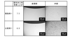
- 2 is an enlarged photograph of each cross section of Example 1 and Comparative Example 1.
- FIG. It is the top view which looked at the outer ring from the track surface side. It is a model figure showing the contact of two objects. It is an iso-stress diagram under a contact surface.
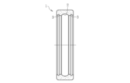
- FIG. 1 a shows a cross-sectional view of a rolling bearing race according to an embodiment of the present invention.
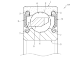
- the bearing ring shown in the figure is an outer ring 1 which is a constituent member of a single row ball bearing, and has an annular raceway surface 2 on which a ball as a rolling element rolls at a substantially central portion in the axial direction of the inner diameter surface thereof.
- annular seal mounting grooves 3 are formed as seal portions.
- a seal member 9 that seals a space between the inner peripheral surface of the outer ring 1 and the outer peripheral surface of the inner ring 5 is fixed to the seal attachment groove 3.
- the seal member 9 includes a member that comes into contact with the mating raceway (inner ring 5) and a member that does not contact the mating raceway.
- the outer ring 1 is formed of a sintered metal obtained by compressing a raw material powder to form a green compact, and sintering the green compact by heating at a sintering temperature or higher.
- the raceway surface 2 and the seal attachment groove 3 are plastic working surfaces formed by performing plastic working on the inner peripheral surface of the sintered metal material. At least the raceway surface 2 of the outer ring 1 is hardened by heat treatment.
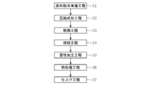
- the outer ring 1 is manufactured through a raw material powder preparation step S1, a compression molding step S2, a degreasing step S3, a sintering step S4, a plastic working step S5, a heat treatment step S6, and a finishing step S7 shown in FIG.
- a raw material powder is manufactured by mixing an iron-based low alloy powder, a carbon powder as a carbon solid solution source, and a molding lubricant responsible for lubrication during molding.
- Ni—Mo-based partially diffused alloy steel powder containing Ni and Mo as alloy components and the balance being Fe and inevitable impurities is used as the iron-based low alloy powder.
- the partial diffusion alloy steel powder used in this embodiment is obtained by diffusion-bonding Ni around the Fe—Mo alloy.
- the hardness of the alloy steel powder before sintering is higher than that of steel powder (pre-alloyed steel powder) in which Fe and Ni are completely alloyed by diffusing and attaching a metal such as Ni to the Fe alloy. Therefore, the moldability at the time of compression molding is ensured. As a result, a relatively large amount of Ni can be blended.
- the mixing ratio of Ni in the partial diffusion alloy steel powder of the present embodiment is 0.5 to 5.0 wt%, preferably 1.7 to 2.2 wt%.
- the mixing ratio of Mo in the partially diffused alloy steel powder is 0.5 to 3.0 wt%, preferably 0.8 to 1.1 wt%, and more preferably 0.9 to 1.1 wt%.
- the steel powder used as the base of the partially diffused alloy steel powder there are atomized powder, reduced powder, and the like. However, since the reduced powder has a porous particle and is difficult to increase in density, in this embodiment, pores are not formed. Solid atomized powder that does not have, especially water atomized powder is used in consideration of cost.
- the partial diffusion alloy steel powder the one in which Ni is diffusion-bonded around the Fe-Mo alloy is exemplified, but the alloy powder in which Ni or Mo is diffusion-bonded around the pure iron powder should be used. You can also.
- This partially diffused alloy steel powder is soft and has the same hardness as pure iron powder.
- a micro Vickers hardness of less than 120HV0.05, desirably less than 100HV0.05, more preferably less than 90HV0.05 is used.
- This hardness is lower than the particle hardness (approximately 120 HV 0.05 or more) in the Fe—Cr—Mo based complete alloy powder (pre-alloy powder) used in Patent Document 3. Therefore, compared to this type of complete alloy powder, it becomes easier to increase the density even with the same applied pressure.
- a partially diffused alloy steel powder having a maximum particle size of 500 ⁇ m or less (preferably 250 ⁇ m or less, more preferably 200 ⁇ m or less).
- This particle size can be obtained by sieving the obtained powder using a sieve having an upper limit particle size (for example, 500 ⁇ m).
- an upper limit particle size for example, 500 ⁇ m.
- the particle size may be increased by granulation in order to prevent a decrease in fluidity of the powder in the mold, but the partial diffusion alloy steel powder of this embodiment has a particle size of Is large and fluidity is good, so granulation is basically unnecessary.
- the carbon powder for example, artificial graphite powder is used.
- the graphite powder having a particle size D90 of 8 ⁇ m or less is used, preferably 6 ⁇ m or less, more preferably 4 ⁇ m or less.
- the graphite powder having a particle diameter D90 of 2 ⁇ m or more, preferably 3 ⁇ m or more is used.
- the blending ratio of the graphite powder is 0.35 wt% or less, preferably 0.3 wt% or less, more preferably 0.25 wt% or less with respect to the entire mixed powder. Further, the blending ratio of the graphite powder is 0.05 wt% or more, preferably 0.1 wt% or more, more preferably 0.15 wt% or more with respect to the whole mixed powder.
- carbon powder carbon black, ketjen black, nanocarbon powder and the like can be used in addition to the graphite powder. Two or more of these powders can be used.
- a known lubricant powder such as metal soap (for example, zinc stearate) or amide wax (for example, ethylene bisstearamide) can be arbitrarily selected and used.
- the type of lubricant powder is not limited as long as it is a component that does not remain in the raw material after sintering. Two or more types of molding lubricants can be used in combination.
- the powdery material 10 is molded by charging and filling the raw material powder into the cavity of the molding die and compressing it.
- the molding at this time is performed by a molding machine suitable for continuous production such as uniaxial and multiaxial pressure molding, CNC press molding, and the like.
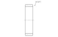
- the green compact 10 formed in the compression molding step S2 is formed into a ring shape similar to the outer ring 1 shown in FIG. 1a, but both the inner diameter surface and the outer diameter surface are uneven. It is a smooth cylindrical surface with no surface.
- the molding lubricant is liquefied by the above-described high pressure, and the solid lubricant that has been liquefied diffuses and permeates between the raw material powders.
- the above molding pressure is only a guide.
- the density and pore size of the sintered body are important. Therefore, depending on the type of powder used and molding conditions, molding may be performed at a pressure lower than the above molding pressure. Absent.
- warm molding was used in which the mold and powder were heated to 60 ° C. or higher, or mold lubrication was used to reduce the amount of molding lubricant used.
- a molding machine can also be used.
- the molding lubricant contained in the green compact 10 is removed.
- Degreasing can be performed under the same conditions as those for producing a general sintered metal product.
- the degreased green compact 10 is heated at the sintering temperature or higher to form a sintered metal material 10 '.
- the sintering temperature is 1150 ° C. or higher and 1350 ° C. or lower, more preferably 1250 ° C. or higher and 1300 ° C. or lower so that a dense sintered metal material 10 ′ having small pores can be obtained.
- the sintered metal material 10 ′ after sintering has a relative density of 90% or more (preferably 95% or more, more preferably 97% or more).
- the raceway surface 2 and the seal mounting groove 3 are formed on the inner diameter surface of the sintered metal material 10 'by performing plastic working on the sintered metal material 10' formed as described above. Is done.
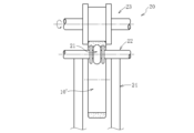
- These moldings can be simultaneously performed using, for example, a rolling machine (ring rolling machine) 20 as shown in FIG.
- the rolling machine 20 includes a shaft-shaped mandrel 22 having a mold portion 21 for forming the raceway surface 2 and the seal mounting groove 3 on the outer periphery, and a drive (not shown) in contact with the outer diameter surface of the sintered metal material 10 ′.
- a die roll 23 that rotates in response to the output of the source and a support roll 24 that supports the rotation of the mandrel 22 are provided.
- the raceway surface 2 and the two seal mounting grooves 3 may be molded separately or sequentially, as described above. Further, the raceway surface 2 and the seal mounting groove 3 may be formed so as to be accompanied by a reduction in the thickness and diameter of the metal sintered body 10 ′, or a reduction in the thickness and diameter of the metal sintered body 10 ′. You may go without accompanying.
- the plastic working method is not limited to rolling, and cold rolling processing in which the sintered metal material 10 ′ is rolled while rotating at room temperature, and burnishing processing can also be employed. Regardless of which plastic working method is employed, the accuracy of the raceway surface 2 and the seal mounting groove 3 and the surroundings thereof can be improved if the plastic working is carried out cold compared to the case where the plastic working is carried out warm or hot. The density can be increased efficiently.
- a process for example, shot peening
- hard particles are projected onto a necessary portion such as the raceway surface 2 and the holes near the surface layer are clogged with the energy.
- the sintered metal material 10 ′ in which the raceway surface 2 and the seal mounting groove 3 are formed is quenched and tempered to harden at least the raceway surface 2 of the sintered metal material 10 ′ and thereby the raceway surface.
- 2 is a process of ensuring the rolling fatigue life required for 2.
- various quenching treatments or surface hardening treatments
- carburizing, carbonitriding, and induction quenching can be employed in addition to continuous quenching.
- the finishing step S7 is a finishing process such as grinding, polishing, lapping, super-finishing, etc., on a predetermined portion (for example, the raceway surface 2 or the seal mounting groove 3) of the sintered metal body 10 ′ that has undergone the heat treatment step S6. Is a step of further improving the accuracy of a predetermined portion of the sintered metal body 10 ′ by applying one or more of the above.
- the finishing step S7 may be performed as necessary, and is not necessarily performed. Even if the finishing process is executed in the finishing step S7, the amount of processing (processing time) is extremely small, and therefore the influence on the yield and the number of processing steps is very small.
- the outer ring 1 manufactured through the above steps has a high density, it is possible to obtain the same mechanical strength as the outer ring 1 made of melted material. Further, since the raceway is made of sintered metal and the raceway surface 2 and the seal attachment groove 3 are formed by plastic working, it can be formed into a near net shape and the material yield is improved. Therefore, it is possible to reduce the cost of the rolling bearing.
- FIG. 5 shows a single row ball bearing 40 which is a kind of rolling bearing.
- a ball bearing 40 shown in FIG. 1 includes an outer ring 1 having an annular raceway surface 2 on an inner diameter surface, an inner ring 5 having an annular raceway surface 6 on an outer diameter surface, and both raceway surfaces 2 and 6.
- the inner diameter end of each seal member 9 is in contact with a seal groove 7 provided on the outer peripheral surface of the inner ring 5 to constitute a contact seal.
- the outer diameter end of the seal member 9 is press-fitted and fixed in the seal attachment groove 3 of the outer ring 1.
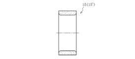
- the cylindrical green compact 15 shown in FIG. 4b is manufactured through the raw material powder preparation step S1 and the compression molding step S2 in the same manner as described above, and then the sintered metal material through the degreasing step S3 and the sintering step S4. 15 'is produced. Thereafter, in the plastic working step S5, the raceway surface 6 and the seal groove 7 as a seal portion are formed. Thereafter, through the heat treatment step S6 and the finishing step S7, the inner ring 5 shown in FIG. 4a is completed.
- FIG. 5 illustrates a single-row ball bearing as the rolling bearing, but other types of rolling bearings such as a cylindrical roller bearing, a tapered roller bearing, a needle roller bearing, an angular ball bearing, and the like are also included.
- the manufacturing procedure described above can also be applied to the manufacturing process of the raceway.
- the above manufacturing procedure can be applied not only to single-row type rolling bearing raceways but also to double-row rolling bearing raceways and thrust rolling bearing raceways having thrust raceway surfaces.
- the above manufacturing procedure can be applied to a bearing ring in which the seal mounting groove 3 and the seal groove are omitted, and also to a rolling bearing without the seal member 9.
- the raceway surface 2 (including the seal attachment groove 3) is plastically processed as in the above-described manufacturing procedure, the pressure applied during the plastic working is hardly exerted at least around the raceway surface 2 of the sintered metal material 10 ′.
- the porous structure can be further densified (densified) compared to the region, for example, the central portion in the thickness direction of the sintered metal material 10 ′. If the periphery of the raceway surface 2 is densely formed, the number of rough atmospheric holes that become a stress concentration source is reduced, and separation of the raceway surface 2 and the like from the origin is less likely to occur. It can be further improved.
- the relative density of the sintered metal material 10 ′ is represented by the following formula (1).
- the true density [g / cm 3 ] in the formula (1) means a theoretical density of a material that does not have pores inside the raw material, such as a melted material, and can be obtained in detail from the following formula (2). it can.
- the relative density is an effective measure for evaluating the degree of densification of the entire raceway, it is not necessarily effective for evaluating the presence or absence of rough atmospheric pores in a region limited to the periphery of the raceway surface.
- the relative density of the entire raceway exceeds the lower limit value, there are cases where there are coarse air holes in the vicinity of the raceway surface, but there are cases where coarse air holes exist, and this coarse air hole is expected to be the starting point of separation.
- it is conceivable to define a relative density limited to the periphery of the raceway surface it is not easy to strictly measure the relative density of a part of the raceway.
- the region to be densified by plastic working should be originally determined according to the load (surface pressure) applied to the raceway surface 2.
- the envelope of the largest hole estimated to be present in at least the critical volume of the bearing ring (generally a depth at which stress of 90% or more of the maximum shear stress is applied).
- the dangerous volume means the volume of the part that has a risk of causing the separation of the raceway surface
- Dangerous volume (contact ellipse major axis) x (circumferential surface length in the circumferential direction) x (depth at which 90% of the maximum shear stress acts) It is represented by
- the depth of the maximum shear stress ⁇ 45 (maximum shear stress acting at an angle of 45 ° with respect to the surface) can be calculated by the method described below.
- the object 1 is considered as an inner ring and the object 2 is considered as a ball (sphere).
- the sum ⁇ of the principal curvature ⁇ of the contact object is It is represented by The principal curvature ⁇ is the reciprocal of the radius, and has a positive sign on the convex surface and a negative sign on the concave surface.
- the auxiliary variable cos ⁇ used in the subsequent calculations is It is.
- ⁇ Hertzian contact coefficient
- ⁇ Poisson's ratio
- ⁇ oil kinematic viscosity
- the auxiliary variable cos ⁇ , the Hertzian contact coefficient and ⁇ , and the kinematic viscosity ⁇ of the oil can also be calculated from the following equations using the complete elliptic integral as a medium.
- K and E are first-type and second-type complete elliptic integrals, which are values represented by the following equations.
- K and E can be obtained from the numerical table.
- the maximum value of the hole envelope area is estimated using extreme value statistics. Specifically, the square root ⁇ area max of the estimated maximum hole envelope area is calculated through the following procedure.
- the specimen subjected to the mirror polishing is observed with a microscope, and an image of the y region having the defined reference area S 0 (mm 2 ) is acquired.
- the obtained image is binarized using image analysis software, and the envelope area of the holes is analyzed.
- the largest envelope area obtained is defined as the maximum hole envelope area in the reference area S 0 (mm 2 ), and its square root is defined as ⁇ area max in that region. This measurement is repeated n times while changing the inspection region.
- ⁇ area max is taken on the coordinate horizontal axis of the extreme value probability sheet, and the above result is plotted to obtain an extreme value distribution (the vertical axis of the extreme value probability sheet takes F or y).
- An approximate straight line obtained by the least square method is extrapolated with respect to the extreme value distribution to obtain a and b represented by Expression 16.
- y is the normalization variable represented by Formula 17
- T is the recursion period represented by Formula 18
- V is the volume (mm 3 ) of the estimation target region
- V 0 is the reference volume (mm) represented by Formula 19. 3 )
- h is an average value (mm) of the measured ⁇ area max, j represented by Equation 20.
- the powders were filled in dies of outer diameter ⁇ 48 mm ⁇ inner diameter ⁇ 34 mm and outer diameter ⁇ 32 mm ⁇ inner diameter ⁇ 16 mm, uniaxially pressed, and then sintered at 1250 ° C. for 150 minutes in an inert gas atmosphere consisting of nitrogen and hydrogen.
- a ring-shaped sintered metal material having a density of 7.5 g / cm 3 was obtained.
- the former is a sintered metal material for the outer ring and the latter is an inner ring.
- the density measurement result is based on the Archimedes method.
- the dimensional variation between the test pieces was made uniform within a predetermined region by passing through a dimensional correction process called sizing. .
- the plastic processed product is carburized at 880 ° C., heated to 840 ° C., quenched, tempered at 180 ° C., and then subjected to a finishing process by polishing, whereby an outer ring having an outer diameter of ⁇ 62 mm ⁇ inner diameter of ⁇ 52.1 mm
- an inner ring having an outer diameter of ⁇ 40 mm ⁇ an inner diameter of ⁇ 30 mm was obtained (hereinafter, the inner and outer rings are referred to as “Example 1”).
- the inner and outer rings conform to JIS standard 6206 model bearing inner and outer rings.
- Comparative Example 1 a complete alloy powder containing 1.5 wt% of Cr, 0.2 wt% of Mo, 0.3 wt% of carbon (C), and the balance being iron, is the same as in Example 1.
- the inner and outer rings were produced by the manufacturing method (Comparative Example 1). This is a test piece meeting the conditions described in Patent Document 3, and the sintered density before plastic working is 6.8 g / cm 3 (relative density of about 87%).
- Example 2 For comparison, after molding and sintering in the same manner as in Example 1, the inner and outer rings were formed into a raceway shape by turning rather than plastic working, and carburized and heat-treated and finished as in Example 1 (Comparative Example). 2) and inner and outer rings of 6206 model bearings made of molten material (material: SUJ2, heat treatment: submerged quenching and tempering, open type without seal, C3 gap) were prepared (Comparative Example 3).
- Test method The test conditions for the rolling fatigue life test were a maximum contact surface pressure Pmax of 3.2 GPa and a bearing rotational speed of 3000 rpm. Turbine oil VG56 was used as the lubricating oil, and this clean oil was circulated through the bearing during the test. By monitoring the vibration of the bearing during operation with the vibration detector, damage such as separation occurs in the inner and outer rings of the bearing, and the test is stopped when the vibration of the bearing exceeds the specified value. Was recorded as the life of the bearing. In addition, after the test was stopped, the bearings were disassembled and the inner and outer rings were checked for damage.
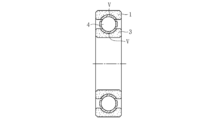
- the predicted volume V is a region extending from the entire raceway surface to a depth of about 0.21 mm (rotating body obtained by rotating the hatched portion V in FIG. 6 once), 350 mm 3 for the outer ring 1, and 3 for the inner ring 3. In was 250mm 3.
- the numerical predictions volume to evaluate a more secure side, the actual risk volume (in the outer ring about 320 mm 3, the inner ring about 210 mm 3) are slightly larger than.
- Example 1 From comparison between Example 1 shown in FIG. 9 and Comparative Examples 1 and 2, it is clear that the smaller the estimated value of the square root ⁇ area max of the maximum hole envelope area, the longer the rolling fatigue life of the bearing ring. became. If this estimated value is less than 50 ⁇ m, it will not be as good as the bearing using the inner and outer rings made of SUJ2 in Comparative Example 3, but it will show a life of about 70 to 80% of the L 10 life of the bearing. Became clear. From this, it is considered that Example 1 may be able to replace the melted material bearing (Comparative Example 3) depending on the use environment and conditions.
- Example 1 the form of damage (flaking) when the rolling fatigue life is reached is considered to be internal starting type separation of the inner ring or the outer ring as in the case of the melted material bearings including SUJ2.
- FIG. 7 b shows a photograph of the inner ring where peeling occurred before and after the test
- FIG. 8 b shows an enlarged photograph of the peeling portion. 7a and 8a are both before the test.
- FIG. 10 shows a representative example of the observation results of the surface layer and the inside (unplastic working region) of the outer ring of Example 1 and Comparative Example 1.
- Example 1 since the density was increased to 7.5 g / cm 3 (relative density of about 96%) before the plastic working, the square root of the estimated maximum envelope area ⁇ There are no coarse pores with an area max exceeding 50 ⁇ m. Since the region where plastic working does not reach is such a dense structure, there are no coarse pores exceeding 50 ⁇ m in the surface layer portion subjected to plastic working (particularly, the region shallower than the depth corresponding to the dangerous volume). Further, in the surface layer portion, no vacancies with a square root of the estimated maximum envelope area exceeding 20 ⁇ m were observed.
- the square root ⁇ area max of the envelope area of the largest hole estimated to exist at least in the predicted volume is less than 50 ⁇ m (preferably less than 40 ⁇ m, more preferably 30 ⁇ m) with the dangerous volume of the raceway as the predicted volume. Therefore, there are no coarse holes around the raceway surface. Therefore, it is possible to prevent the raceway from being damaged, such as peeling, starting from the coarse holes, and to obtain a rolling fatigue life comparable to that of the melted material.
- Fe—Ni—Mo based partially diffused alloy steel is used, but this powder is as soft as pure iron powder as already described. Therefore, the density can be increased at the time of compression molding, and the generation of rough air holes around the raceway surface can be avoided by the synergistic effect of this and densification by plastic working. In addition, the formability when the raceway surface 2 and the like are formed by plastic working is also good. Furthermore, since this powder is easy to obtain and low in cost, it is possible to reduce the cost of the bearing ring and, in turn, the rolling bearing.
- Patent Document 3 also describes the use of stainless steel powder such as SUS420 and bearing steel powder such as SUJ2 in addition to the Fe—Cr—Mo alloy powder of Comparative Example 1. Since the powder contains a large amount of Cr, the same problem as in Comparative Example 1 occurs.
- the numerical value of the predicted volume is slightly larger than the actual dangerous volume, and the region including the entire axial direction of the raceway surface is set as the predicted volume V. (See FIG. 6). This is because the safety is evaluated in consideration of the axial load acting on the bearing. If the critical volume corresponding to the axial width (major axis) of the contact ellipse is the predicted volume V, and at least the plane direction of the maximum hole envelope area within this predicted volume is less than 50 ⁇ m, the rolling fatigue life of the raceway is improved. Can be made.
- the case where the estimated volume V is determined based on the dangerous volume and the square root ⁇ area max of the maximum hole envelope area is estimated is illustrated, but in addition to this, as shown in FIG.
- the square root ⁇ area of the maximum hole envelope area It is also possible to estimate max .
Landscapes
- Engineering & Computer Science (AREA)
- Chemical & Material Sciences (AREA)
- Mechanical Engineering (AREA)
- General Engineering & Computer Science (AREA)
- Materials Engineering (AREA)
- Metallurgy (AREA)
- Organic Chemistry (AREA)
- Manufacturing & Machinery (AREA)
- Crystallography & Structural Chemistry (AREA)
- Thermal Sciences (AREA)
- Physics & Mathematics (AREA)
- Rolling Contact Bearings (AREA)
- Powder Metallurgy (AREA)
- Sealing Of Bearings (AREA)
Abstract
Selon la présente invention, à l'aide d'un moulage par compression d'une poudre d'alliage d'acier partiellement diffusée, puis d'un frittage, un élément métallique fritté (10') est formé et, à l'aide d'un usinage plastique de l'élément métallique fritté (10'), une surface de piste (2) est formée, donnant une bague de roulement (1). Au moins le volume de risque de la bague de roulement (1) est considéré comme un volume prédit, et la racine carrée (√areamax) de la surface d'enveloppe du pore le plus grand, estimé comme étant présent dans au moins le volume prédit, étant établie de façon à être inférieure à 50 µm. Par conséquent, il est possible d'obtenir un roulement qui, tout en étant de faible coût, présente une plus grande durée de vie de fatigue de roulement.
Priority Applications (3)
| Application Number | Priority Date | Filing Date | Title |
|---|---|---|---|
| US15/127,236 US20170108045A1 (en) | 2014-03-20 | 2015-03-19 | Bearing ring and roller bearing having said bearing ring |
| CN201580012768.3A CN106460932B (zh) | 2014-03-20 | 2015-03-19 | 滚道圈以及具有该滚道圈的滚动轴承 |
| EP15765601.8A EP3128193B1 (fr) | 2014-03-20 | 2015-03-19 | Bague de roulement et roulement à rouleaux ayant ladite bague de roulement |
Applications Claiming Priority (2)
| Application Number | Priority Date | Filing Date | Title |
|---|---|---|---|
| JP2014058001A JP2015183706A (ja) | 2014-03-20 | 2014-03-20 | 軌道輪および該軌道輪を有する転がり軸受 |
| JP2014-058001 | 2014-03-20 |
Publications (1)
| Publication Number | Publication Date |
|---|---|
| WO2015141807A1 true WO2015141807A1 (fr) | 2015-09-24 |
Family
ID=54144769
Family Applications (1)
| Application Number | Title | Priority Date | Filing Date |
|---|---|---|---|
| PCT/JP2015/058368 Ceased WO2015141807A1 (fr) | 2014-03-20 | 2015-03-19 | Bague de roulement et roulement à rouleaux ayant ladite bague de roulement |
Country Status (5)
| Country | Link |
|---|---|
| US (1) | US20170108045A1 (fr) |
| EP (1) | EP3128193B1 (fr) |
| JP (1) | JP2015183706A (fr) |
| CN (1) | CN106460932B (fr) |
| WO (1) | WO2015141807A1 (fr) |
Cited By (1)
| Publication number | Priority date | Publication date | Assignee | Title |
|---|---|---|---|---|
| US11078961B2 (en) * | 2018-04-02 | 2021-08-03 | Nsk Ltd. | Intermediary race member of rolling bearing, race, rolling bearing and production method therefor |
Families Citing this family (6)
| Publication number | Priority date | Publication date | Assignee | Title |
|---|---|---|---|---|
| CN107309432B (zh) * | 2017-05-10 | 2020-05-05 | 武汉理工大学 | 一种含油轴承环的粉末冶金-轧制成形的制造方法 |
| DE102018208947A1 (de) * | 2018-06-06 | 2019-12-12 | Aktiebolaget Skf | Wälzlagerring mittels eines Metallspritzgussverfahrens |
| CN109538634A (zh) * | 2018-10-20 | 2019-03-29 | 夏小林 | 一种轴承内圈、其制备方法及轴承 |
| US11313415B2 (en) * | 2019-11-28 | 2022-04-26 | Aktiebolaget Skf | Method for manufacturing a sensor bearing unit, and associated sensor bearing unit |
| CN112975303B (zh) * | 2021-03-24 | 2022-06-10 | 中国航发哈尔滨轴承有限公司 | 一种轻薄系列密封结构轴承外圈的加工方法 |
| CN118527659B (zh) * | 2024-07-19 | 2024-11-22 | 烟台东星大韩粉末冶金有限公司 | 一种高性能粉末冶金含油轴承及其制作方法 |
Citations (5)
| Publication number | Priority date | Publication date | Assignee | Title |
|---|---|---|---|---|
| JPH05263181A (ja) * | 1992-03-19 | 1993-10-12 | Mitsubishi Materials Corp | 高強度および高靭性を有するFe基焼結合金部材の製造法 |
| JPH06145845A (ja) * | 1992-11-02 | 1994-05-27 | Sumitomo Electric Ind Ltd | 焼結摩擦材 |
| JP2002294388A (ja) * | 2000-08-31 | 2002-10-09 | Kawasaki Steel Corp | 鉄基粉末成形用素材、その製造方法および高強度高密度鉄基焼結体の製造方法 |
| JP2006503982A (ja) * | 2002-10-22 | 2006-02-02 | ホガナス アクチボラゲット | 鉄ベースの粉末 |
| JP2013053358A (ja) * | 2011-09-06 | 2013-03-21 | Sumitomo Electric Sintered Alloy Ltd | 焼結部品の製造方法 |
Family Cites Families (11)
| Publication number | Priority date | Publication date | Assignee | Title |
|---|---|---|---|---|
| WO2001032337A1 (fr) * | 1999-10-29 | 2001-05-10 | Kawasaki Steel Corporation | Agent lubrifiant pour moulage a haute temperature, composition de poudre a base de fer pour compactage a haute temperature avec un moule lubrifie et produit forme de haute densite realise a partir de ladite composition, et procede de production d'un produit compact fritte de densite elevee a base de fer |
| JP2004143550A (ja) * | 2002-10-25 | 2004-05-20 | Sanyo Special Steel Co Ltd | Ti添加高強度鋼 |
| JP2004218041A (ja) * | 2003-01-17 | 2004-08-05 | Jfe Steel Kk | 焼結部材及びその製造方法 |
| JP2004251898A (ja) * | 2003-01-31 | 2004-09-09 | Nsk Ltd | 鋼の清浄度評価方法および転がり軸受並びにトロイダル形無段変速装置 |
| JP4301507B2 (ja) * | 2003-07-22 | 2009-07-22 | 日産自動車株式会社 | サイレントチェーン用焼結スプロケットおよびその製造方法 |
| KR101240051B1 (ko) * | 2006-11-20 | 2013-03-06 | 두산인프라코어 주식회사 | 내마모성 베어링 및 그 제조방법 |
| JP5955498B2 (ja) * | 2009-09-29 | 2016-07-20 | Ntn株式会社 | 動力伝達部品の製造方法 |
| JP5059224B2 (ja) * | 2010-11-09 | 2012-10-24 | 新日本製鐵株式会社 | 部品の疲労破壊評価装置、部品の疲労破壊評価方法、及びコンピュータプログラム |
| JP5936838B2 (ja) * | 2010-11-25 | 2016-06-22 | Ntn株式会社 | 転がり軸受用軌道輪の製造方法 |
| JP5825157B2 (ja) * | 2012-03-12 | 2015-12-02 | 新日鐵住金株式会社 | 高周波焼入れ用鋼材 |
| CN103223491A (zh) * | 2013-04-09 | 2013-07-31 | 吴建平 | 一种轴承外圈粉末冶金的制备方法 |
-
2014
- 2014-03-20 JP JP2014058001A patent/JP2015183706A/ja active Pending
-
2015
- 2015-03-19 CN CN201580012768.3A patent/CN106460932B/zh active Active
- 2015-03-19 WO PCT/JP2015/058368 patent/WO2015141807A1/fr not_active Ceased
- 2015-03-19 EP EP15765601.8A patent/EP3128193B1/fr active Active
- 2015-03-19 US US15/127,236 patent/US20170108045A1/en not_active Abandoned
Patent Citations (5)
| Publication number | Priority date | Publication date | Assignee | Title |
|---|---|---|---|---|
| JPH05263181A (ja) * | 1992-03-19 | 1993-10-12 | Mitsubishi Materials Corp | 高強度および高靭性を有するFe基焼結合金部材の製造法 |
| JPH06145845A (ja) * | 1992-11-02 | 1994-05-27 | Sumitomo Electric Ind Ltd | 焼結摩擦材 |
| JP2002294388A (ja) * | 2000-08-31 | 2002-10-09 | Kawasaki Steel Corp | 鉄基粉末成形用素材、その製造方法および高強度高密度鉄基焼結体の製造方法 |
| JP2006503982A (ja) * | 2002-10-22 | 2006-02-02 | ホガナス アクチボラゲット | 鉄ベースの粉末 |
| JP2013053358A (ja) * | 2011-09-06 | 2013-03-21 | Sumitomo Electric Sintered Alloy Ltd | 焼結部品の製造方法 |
Non-Patent Citations (1)
| Title |
|---|
| See also references of EP3128193A4 * |
Cited By (1)
| Publication number | Priority date | Publication date | Assignee | Title |
|---|---|---|---|---|
| US11078961B2 (en) * | 2018-04-02 | 2021-08-03 | Nsk Ltd. | Intermediary race member of rolling bearing, race, rolling bearing and production method therefor |
Also Published As
| Publication number | Publication date |
|---|---|
| EP3128193B1 (fr) | 2022-10-26 |
| EP3128193A1 (fr) | 2017-02-08 |
| EP3128193A4 (fr) | 2018-01-03 |
| CN106460932B (zh) | 2020-08-21 |
| US20170108045A1 (en) | 2017-04-20 |
| CN106460932A (zh) | 2017-02-22 |
| JP2015183706A (ja) | 2015-10-22 |
Similar Documents
| Publication | Publication Date | Title |
|---|---|---|
| CN106460932B (zh) | 滚道圈以及具有该滚道圈的滚动轴承 | |
| JP6688287B2 (ja) | プレアロイ鉄基粉末、プレアロイ鉄基粉末を含有する鉄基粉末混合物、及び鉄基粉末混合物からプレス成形および焼結した部品を製造する方法 | |
| US9945419B2 (en) | Retainer | |
| JP2876715B2 (ja) | 転がり軸受 | |
| JP6389031B2 (ja) | 円錐ころ軸受 | |
| JP5936838B2 (ja) | 転がり軸受用軌道輪の製造方法 | |
| CN107923027A (zh) | 滑动部件及其制造方法 | |
| CA2615882C (fr) | Anneau de roulement en metal composite a resistance et capacite elevees | |
| EP3097999A1 (fr) | Pièce mécanique frittée et son procédé de fabrication | |
| JPWO2018216461A1 (ja) | 焼結部材の製造方法 | |
| US20160311026A1 (en) | Machine component using powder compact and method for producing same | |
| JP2020172698A (ja) | 焼結部品の製造方法、及び焼結部品 | |
| JP2020172697A (ja) | 焼結部品の製造方法、及び焼結部品 | |
| JP6444621B2 (ja) | 焼結機械部品 | |
| CN105308340B (zh) | 轴承零件及其形成方法 | |
| JP2010209965A (ja) | 転がり軸受用保持器 | |
| JP2008308706A (ja) | 円錐ころ軸受 | |
| JP2008267525A (ja) | 転がり軸受 | |
| JP2019219018A (ja) | 転がり軸受用保持器およびその製造方法 | |
| JP2019095044A (ja) | 転動部品、軸受およびそれらの製造方法 | |
| JP2022045034A (ja) | 車輪用軸受装置 | |
| JP2025025143A (ja) | 軸受部品 | |
| JP2024076033A (ja) | ハブユニット軸受及び、ハブ輪の製造方法 | |
| JP2025025144A (ja) | 軸受部品 | |
| JP2023142724A (ja) | 軸受部品 |
Legal Events
| Date | Code | Title | Description |
|---|---|---|---|
| 121 | Ep: the epo has been informed by wipo that ep was designated in this application |
Ref document number: 15765601 Country of ref document: EP Kind code of ref document: A1 |
|
| WWE | Wipo information: entry into national phase |
Ref document number: 15127236 Country of ref document: US |
|
| NENP | Non-entry into the national phase |
Ref country code: DE |
|
| REEP | Request for entry into the european phase |
Ref document number: 2015765601 Country of ref document: EP |
|
| WWE | Wipo information: entry into national phase |
Ref document number: 2015765601 Country of ref document: EP |