WO2015141840A1 - 良加工性鋼線材およびその製造方法 - Google Patents
良加工性鋼線材およびその製造方法 Download PDFInfo
- Publication number
- WO2015141840A1 WO2015141840A1 PCT/JP2015/058566 JP2015058566W WO2015141840A1 WO 2015141840 A1 WO2015141840 A1 WO 2015141840A1 JP 2015058566 W JP2015058566 W JP 2015058566W WO 2015141840 A1 WO2015141840 A1 WO 2015141840A1
- Authority
- WO
- WIPO (PCT)
- Prior art keywords
- less
- wire
- steel wire
- steel
- cementite
- Prior art date
- Legal status (The legal status is an assumption and is not a legal conclusion. Google has not performed a legal analysis and makes no representation as to the accuracy of the status listed.)
- Ceased
Links
Images

Classifications
-
- C—CHEMISTRY; METALLURGY
- C21—METALLURGY OF IRON
- C21D—MODIFYING THE PHYSICAL STRUCTURE OF FERROUS METALS; GENERAL DEVICES FOR HEAT TREATMENT OF FERROUS OR NON-FERROUS METALS OR ALLOYS; MAKING METAL MALLEABLE, e.g. BY DECARBURISATION OR TEMPERING
- C21D9/00—Heat treatment, e.g. annealing, hardening, quenching or tempering, adapted for particular articles; Furnaces therefor
- C21D9/52—Heat treatment, e.g. annealing, hardening, quenching or tempering, adapted for particular articles; Furnaces therefor for wires; for strips ; for rods of unlimited length
- C21D9/525—Heat treatment, e.g. annealing, hardening, quenching or tempering, adapted for particular articles; Furnaces therefor for wires; for strips ; for rods of unlimited length for wire, for rods
-
- C—CHEMISTRY; METALLURGY
- C21—METALLURGY OF IRON
- C21D—MODIFYING THE PHYSICAL STRUCTURE OF FERROUS METALS; GENERAL DEVICES FOR HEAT TREATMENT OF FERROUS OR NON-FERROUS METALS OR ALLOYS; MAKING METAL MALLEABLE, e.g. BY DECARBURISATION OR TEMPERING
- C21D1/00—General methods or devices for heat treatment, e.g. annealing, hardening, quenching or tempering
- C21D1/34—Methods of heating
- C21D1/44—Methods of heating in heat-treatment baths
- C21D1/46—Salt baths
-
- C—CHEMISTRY; METALLURGY
- C21—METALLURGY OF IRON
- C21D—MODIFYING THE PHYSICAL STRUCTURE OF FERROUS METALS; GENERAL DEVICES FOR HEAT TREATMENT OF FERROUS OR NON-FERROUS METALS OR ALLOYS; MAKING METAL MALLEABLE, e.g. BY DECARBURISATION OR TEMPERING
- C21D8/00—Modifying the physical properties of ferrous metals or ferrous alloys by deformation combined with, or followed by, heat treatment
- C21D8/06—Modifying the physical properties of ferrous metals or ferrous alloys by deformation combined with, or followed by, heat treatment during manufacturing of rods or wires
-
- C—CHEMISTRY; METALLURGY
- C22—METALLURGY; FERROUS OR NON-FERROUS ALLOYS; TREATMENT OF ALLOYS OR NON-FERROUS METALS
- C22C—ALLOYS
- C22C38/00—Ferrous alloys, e.g. steel alloys
-
- C—CHEMISTRY; METALLURGY
- C22—METALLURGY; FERROUS OR NON-FERROUS ALLOYS; TREATMENT OF ALLOYS OR NON-FERROUS METALS
- C22C—ALLOYS
- C22C38/00—Ferrous alloys, e.g. steel alloys
- C22C38/002—Ferrous alloys, e.g. steel alloys containing In, Mg, or other elements not provided for in one single group C22C38/001 - C22C38/60
-
- C—CHEMISTRY; METALLURGY
- C22—METALLURGY; FERROUS OR NON-FERROUS ALLOYS; TREATMENT OF ALLOYS OR NON-FERROUS METALS
- C22C—ALLOYS
- C22C38/00—Ferrous alloys, e.g. steel alloys
- C22C38/02—Ferrous alloys, e.g. steel alloys containing silicon
-
- C—CHEMISTRY; METALLURGY
- C22—METALLURGY; FERROUS OR NON-FERROUS ALLOYS; TREATMENT OF ALLOYS OR NON-FERROUS METALS
- C22C—ALLOYS
- C22C38/00—Ferrous alloys, e.g. steel alloys
- C22C38/04—Ferrous alloys, e.g. steel alloys containing manganese
-
- C—CHEMISTRY; METALLURGY
- C22—METALLURGY; FERROUS OR NON-FERROUS ALLOYS; TREATMENT OF ALLOYS OR NON-FERROUS METALS
- C22C—ALLOYS
- C22C38/00—Ferrous alloys, e.g. steel alloys
- C22C38/06—Ferrous alloys, e.g. steel alloys containing aluminium
-
- C—CHEMISTRY; METALLURGY
- C22—METALLURGY; FERROUS OR NON-FERROUS ALLOYS; TREATMENT OF ALLOYS OR NON-FERROUS METALS
- C22C—ALLOYS
- C22C38/00—Ferrous alloys, e.g. steel alloys
- C22C38/18—Ferrous alloys, e.g. steel alloys containing chromium
-
- C—CHEMISTRY; METALLURGY
- C22—METALLURGY; FERROUS OR NON-FERROUS ALLOYS; TREATMENT OF ALLOYS OR NON-FERROUS METALS
- C22C—ALLOYS
- C22C38/00—Ferrous alloys, e.g. steel alloys
- C22C38/18—Ferrous alloys, e.g. steel alloys containing chromium
- C22C38/40—Ferrous alloys, e.g. steel alloys containing chromium with nickel
-
- C—CHEMISTRY; METALLURGY
- C22—METALLURGY; FERROUS OR NON-FERROUS ALLOYS; TREATMENT OF ALLOYS OR NON-FERROUS METALS
- C22C—ALLOYS
- C22C38/00—Ferrous alloys, e.g. steel alloys
- C22C38/18—Ferrous alloys, e.g. steel alloys containing chromium
- C22C38/40—Ferrous alloys, e.g. steel alloys containing chromium with nickel
- C22C38/44—Ferrous alloys, e.g. steel alloys containing chromium with nickel with molybdenum or tungsten
-
- C—CHEMISTRY; METALLURGY
- C22—METALLURGY; FERROUS OR NON-FERROUS ALLOYS; TREATMENT OF ALLOYS OR NON-FERROUS METALS
- C22C—ALLOYS
- C22C38/00—Ferrous alloys, e.g. steel alloys
- C22C38/18—Ferrous alloys, e.g. steel alloys containing chromium
- C22C38/40—Ferrous alloys, e.g. steel alloys containing chromium with nickel
- C22C38/46—Ferrous alloys, e.g. steel alloys containing chromium with nickel with vanadium
-
- C—CHEMISTRY; METALLURGY
- C22—METALLURGY; FERROUS OR NON-FERROUS ALLOYS; TREATMENT OF ALLOYS OR NON-FERROUS METALS
- C22C—ALLOYS
- C22C38/00—Ferrous alloys, e.g. steel alloys
- C22C38/18—Ferrous alloys, e.g. steel alloys containing chromium
- C22C38/40—Ferrous alloys, e.g. steel alloys containing chromium with nickel
- C22C38/50—Ferrous alloys, e.g. steel alloys containing chromium with nickel with titanium or zirconium
-
- C—CHEMISTRY; METALLURGY
- C22—METALLURGY; FERROUS OR NON-FERROUS ALLOYS; TREATMENT OF ALLOYS OR NON-FERROUS METALS
- C22C—ALLOYS
- C22C38/00—Ferrous alloys, e.g. steel alloys
- C22C38/18—Ferrous alloys, e.g. steel alloys containing chromium
- C22C38/40—Ferrous alloys, e.g. steel alloys containing chromium with nickel
- C22C38/54—Ferrous alloys, e.g. steel alloys containing chromium with nickel with boron
-
- C—CHEMISTRY; METALLURGY
- C21—METALLURGY OF IRON
- C21D—MODIFYING THE PHYSICAL STRUCTURE OF FERROUS METALS; GENERAL DEVICES FOR HEAT TREATMENT OF FERROUS OR NON-FERROUS METALS OR ALLOYS; MAKING METAL MALLEABLE, e.g. BY DECARBURISATION OR TEMPERING
- C21D2211/00—Microstructure comprising significant phases
- C21D2211/003—Cementite
-
- C—CHEMISTRY; METALLURGY
- C21—METALLURGY OF IRON
- C21D—MODIFYING THE PHYSICAL STRUCTURE OF FERROUS METALS; GENERAL DEVICES FOR HEAT TREATMENT OF FERROUS OR NON-FERROUS METALS OR ALLOYS; MAKING METAL MALLEABLE, e.g. BY DECARBURISATION OR TEMPERING
- C21D9/00—Heat treatment, e.g. annealing, hardening, quenching or tempering, adapted for particular articles; Furnaces therefor
- C21D9/52—Heat treatment, e.g. annealing, hardening, quenching or tempering, adapted for particular articles; Furnaces therefor for wires; for strips ; for rods of unlimited length
Definitions
- the present invention is an internal process that is a fundamental process of fracture and crack generation in wire drawing and bolt forming, which is a typical example of wire forming and bolt forming that can be said to be essential in the manufacturing process that is commercialized using wire. It is an invention in which the processing performance of a steel wire is improved by the effect of delaying the formation of microvoids, and is characterized in that it can be applied to the general processing field of steel wire.
- a prior art using spheroidizing annealing includes an austenite crystal grain size of 100 ⁇ m or more and a ferrite fraction of 20% or less.
- Cr is added as a method for promoting cementite spheroidization after annealing.
- the steel structure is adjusted so that pseudo pearlite is 10 area% or more, bainite is 75 area% or less, and ferrite is 60 area% or less.
- the improvement of workability and the reduction of deformation resistance after conversion are achieved.
- Patent Document 2 discloses a steel exhibiting excellent cold forgeability by balancing the work performance and the deformation resistance by defining the area% of pseudo pearlite, bainite and ferrite within a desirable range. It is characterized by obtaining a wire rod.
- Patent Document 3 discloses that in producing a rolled steel wire such as eutectoid steel, in a consistent process from casting to wire rod rolling, the steel material is rolled without undergoing transformation from the austenite phase and immediately subjected to isothermal transformation heat treatment. By making it, it is characterized by manufacturing a high-tensile steel wire having excellent wire drawing workability.
- Patent Documents 1 to 4 when a steel wire is produced by subjecting a steel wire to severe processing, the cause of the breakage of the steel wire is not studied. Moreover, the influence which the behavior of the micro void generated when the steel wire is formed on the steel wire has on the breakage of the steel wire has not been studied.
- the present invention has been made in view of such a situation, and in order to realize stable wire drawing performance and forging performance, cementite is aimed at delaying the formation of internal microvoids formed during processing. It aims at providing the steel wire which is characterized by having a structure
- the gist of the present invention for achieving the above object is as follows. (1) By mass%, C: 0.20 to 0.60%, Si: 0.15 to 0.30%, Mn: 0.25 to 0.60%, P: ⁇ 0.020%, S: ⁇ 0.010%, a steel wire having a steel component that is the balance Fe and inevitable impurities, and has cementite as an internal structure, and among the cementite in a cross section perpendicular to the longitudinal direction of the wire, When the number ratio is 80% or more, a good workability steel wire material having a minor axis of 0.1 ⁇ m or less and an aspect ratio comprising a ratio of the major axis to the minor axis of 2.0 or less.
- the present invention enables the provision of a wire having excellent processing performance by suppressing the occurrence of breakage and cracking during processing in fields such as wire drawing and cold heading, which are representative manufacturing processes of steel wires, It can contribute to the stabilization of production activities in the field.
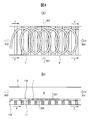
- FIG. 1 is a schematic top view explaining the in-line heat treatment process of a steel wire
- (b) is a schematic side sectional view explaining the in-line heat treatment process of a steel wire.
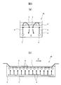
- (A) is a schematic front cross-sectional view of the apparatus 10 which performs the in-line heat processing process which laid the piping 2 which discharges the molten salt A in a cooling tank
- (b) is a schematic sectional side view of the said apparatus 10.
- the steel component according to the present invention the aspect ratio (major axis) / minor axis) regarding the structure of cementite and the abundance ratio by aspect ratio with respect to the total amount of cementite in the cross section and the content of the minor axis size and production method, the lower limit of the appropriate range, The contents defining the upper limit will be specifically described. All percentages relating to the steel component indicate mass%.
- C 0.20 to 0.60%
- C is an element necessary for ensuring strength, and if it is less than 0.20%, it will not be possible to maintain appropriate strength for the application. If it exceeds 0.60%, the load stress at the time of cold forging becomes high, so the influence on the punching life for forging begins to appear.
- Si 0.15-0.30% Si is used as a deoxidizing material. When it is less than 0.15%, deoxidation is insufficient, and surface defects due to pinhole defects in the casting stage occur on the surface of the steel slab. Further, if it exceeds 0.30%, Si is concentrated at the interface between the scale and the base iron due to the selective oxidation in the slab heating stage, and the upper limit is set to 0.30% because there is an adverse effect on the descaling property.
- Mn 0.25 to 0.60%
- Mn is an element necessary for deoxidation like Si. Further, it is an important element for ensuring ductility during hot rolling.
- the lower limit is set to 0.25% in order to avoid deoxidation shortage, and the upper limit is set to 0.60%. If the upper limit is added, the amount of solid solution strengthening increases, and the deformation resistance during forging is increased. This is because the tool life is deteriorated and the tool life is deteriorated.
- P ⁇ 0.020%
- P is an element having the characteristic of deteriorating the ductility of the steel material. Moreover, since the segregation ratio is high, concentration to the segregated portion occurring in the production stage is likely to occur. For this reason, the upper limit was made 0.020%.
- S ⁇ 0.010% S combines with Mn in steel to produce MnS. Further, since S segregates in the central part during the refining and solidification process of steel, MnS accumulates in the central part. If S exceeds 0.010%, an internal crack may be formed during wire drawing and the wire may be disconnected. Therefore, S is set to 0.010% or less.
- the basic chemical composition of the steel wire rod of the present invention is as described above.
- Al 0.06% or less
- Cr 1.50% or less
- Mo 0.50% or less
- Ni 1.00% or less
- V 0.50% or less
- B 0.005% or less
- Ti containing one or more elements selected from the group consisting of 0.05% or less
- hardenability Advantages such as improvement and strength improvement of cold forging are obtained.
- Al 0.06% or less
- Al has the effect of fixing N and suppressing dynamic strain aging during cold forging and reducing deformation resistance. In order to acquire this effect, it is preferable to make it contain at least 0.01%. However, the upper limit is set to 0.06% because the toughness is reduced if excessively contained.
- V 0.50% or less V may be added for the purpose of precipitation strengthening. However, if added in a large amount, it causes deterioration of ductility, so it is suppressed within the above range.
- B 0.0050% or less
- Ti 0.05% or less
- B is an element that improves hardenability, and may be added if necessary. However, if excessively contained, the toughness is degraded, so the upper limit is made 0.005%.
- Ti is an element effective in reducing deformation resistance during cold forging due to the effect of suppressing dynamic aging by fixing solute N, and may be added as necessary. However, if it is contained excessively, coarse TiN precipitates and cracks starting from this coarse TiN are likely to occur, so the upper limit is made 0.05%.
- cementite produced in a lamellar shape (with an aspect ratio of 10 or more) has a high ratio of adjacent cementite microvoids connected.
- the aspect ratio of 2 to 10 both single and connected forms are mixed.
- observation by this method is limited to a local visual field in the cross section.
- steel wire No. of the present invention shown in Table 3.
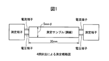
- Steel wire Nos. 1 to 6 and Comparative Example Steel wires were manufactured using 11 to 16, respectively, and an attempt was made to measure the electrical resistance of each steel wire by the 4-probe method shown in FIG.
- the steel wire made of the steel wire material of the present invention is more suppressed in the formation of internal microvoids, and the number of microvoids generated is small, so the electrical resistance value may be low. confirmed.
- the inventors in the process of observing the internal microvoids in detail while observing the structure of the structure in detail, dare to give more stringent drawing conditions than usual at the initial stage to artificially create microvoids. It was found that there is a close relationship between the formation of microvoids and the cementite morphology. Focusing on the shape of cementite, it was found that when the ratio of the major axis to the minor axis (hereinafter referred to as aspect ratio) is 2 or less, a crack is generated independently from the iron-iron interface around cementite.
- Step Step 1 The steel slab is heated in the range of 950 ° C. to 1080 ° C., and the heated steel slab is wire-rolled.
- the temperature is lower than 950 ° C.
- the internal heat deviation of the steel slab increases within a normal holding time, and there arises a problem associated with the warpage of the steel material during rolling and an increase in reaction force.
- the reason why the upper limit temperature is set to 1080 ° C. is that an increase in the ⁇ (austenite) particle size tends to occur when the heating temperature is higher than this. Such an increase in ⁇ particle size more than necessary affects the skin quality of the surface free surface of the final product, so the upper limit was set to 1080 ° C.
- ⁇ Wear removal process> The steel piece after the heating step is subjected to a scraping step in the range of 750 ° C to 900 ° C.
- the lower limit temperature was set to 750 ° C. in order to stably perform the heat treatment after cutting, although there was some variation depending on the wire diameter of the wire rod rolling. Further, when the temperature is 750 ° C. or lower, pearlite transformation occurs before the heat treatment, and the target metal structure cannot be imparted. On the other hand, scraping at a temperature exceeding 900 ° C. is not preferable because it causes an increase in surface oxidation.
- In-line heat treatment is performed by immersing the wire material after the staking step in a cooling bath in which a molten salt of at least one of potassium nitrate and sodium nitrate is stirred at a predetermined flow rate at 400 ° C. to 430 ° C.
- the lower limit temperature of the in-line heat treatment temperature is set to 400 ° C., because the lower bainite structure becomes a lower bainite structure, and the hardness of the substrate increases rapidly, so that the tool life used in the forging process and the like deteriorates. It is.
- the upper limit temperature of the heat treatment is set to 430 ° C., and if the temperature exceeds this, it becomes a region where the pseudo pearlite structure is mixed in the upper bainite, so that it is difficult to control the aspect ratio of the cementite. This is because an important microvoid formation delay effect cannot be exhibited.
- an agitation flow rate that generates the jet described here plays an important role in the present invention.
- the steel wire is immersed in the cooling tank in the form of a coil such as a loose coil.
- the steel wire to be heat-treated is coiled, so the collision direction of the molten salt to the steel wire varies depending on the location and the constant collision. It seems that it is practically difficult to set the direction.
- the directions D12, D22, and D32 are positive directions, and the directions D11, D21, and D31 are negative directions, and each other in the vicinity of the coil surfaces 11A and 11B of the steel wire 1
- the maximum flow rate and the minimum flow rate of the molten salt A in each of the three vertical directions were measured.
- the average flow velocity in each of the three directions perpendicular to each other obtained from the maximum flow velocity and the minimum flow velocity is defined as “stirring flow velocity vector”
- the magnitude of the stirring flow velocity vector is defined as “stirring flow velocity vector”
- the relationship between the stirring flow rate and the abundance ratio of the cementite was investigated.
- the material in the cross section is at a level that does not substantially cause a problem if the stirring speed of the molten salt is 0.5 m / s or more with respect to the coil surface of the steel wire. It was found that the uniformity of the can be improved.
- the measurement position of the stirring flow velocity may be a gap between adjacent rollers of the conveyance roller 6 or the like.
- the stirring flow rate is particularly preferably measured at a position where the flow rate until reaching the coil surfaces 11A and 11B is maintained substantially constant.
- the wire rod is not sufficiently cooled by the molten salt, so that the aspect ratio of cementite may not be controlled to 2 or less. Therefore, the wire may be cooled by directly stirring the molten salt in the cooling tank using a stirrer or by discharging the molten salt itself in the molten salt in the cooling tank.
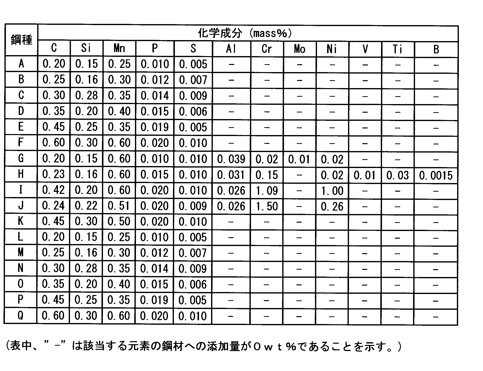
- Table 2-1 shows the chemical composition of the test steel used in the trial production.
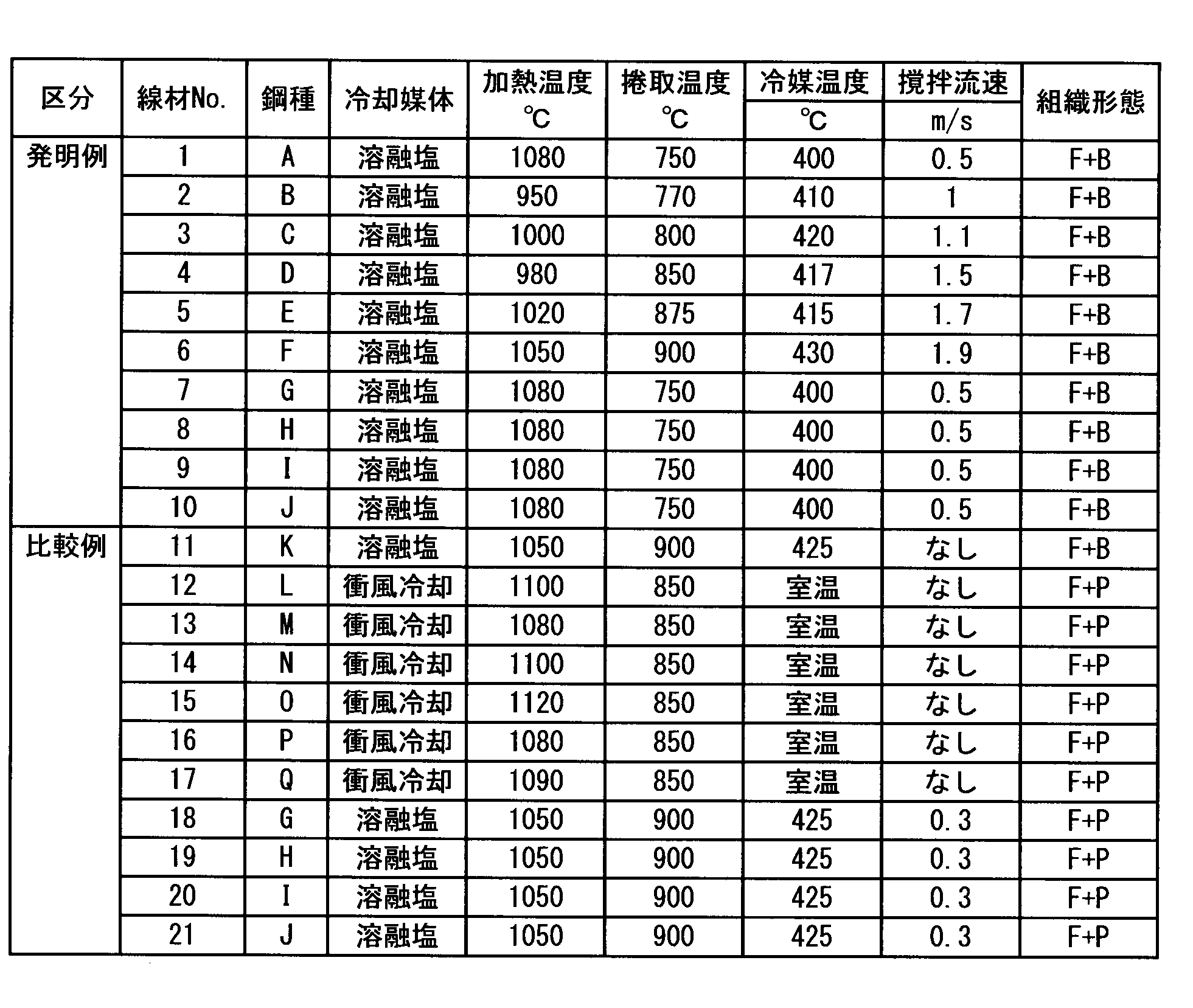
- the steel shown in Table 2-1 was melted and cast into a slab size of 300 mm ⁇ 500 mm by continuous casting, and then a steel slab of 122 mm square was obtained by split rolling. After reheating this steel slab, wire rolling was performed, and wire No. which is an example of the present invention. 1 to 10 and wire No. Nos. 18 to 21 were subjected to a direct heat treatment by dipping in the molten salt in the in-line heat treatment apparatus 10 shown in FIGS. Wire No. No. 11 does not stir the molten salt during direct cooling after wire rod rolling. Also, wire No. Nos. 12 to 17 were made into slabs of the same size by continuous casting, then steel slabs of the same size by split rolling, and cooling after wire rolling was performed by heat treatment by blast cooling to make a 5.5 mm ⁇ wire rod This is an example.
- the in-line heat treatment of the wire material after stripping is performed so that the entire coiled steel wire material 1 is immersed below the liquid surface 5 of the molten salt A. It carried out by conveying the said steel wire 1 in the F direction with the conveyance roller 6 in the in-line heat processing apparatus 10.
- FIG. The in-line heat treatment apparatus 10 has a structure in which a pipe 2 for discharging the molten salt A is laid in the cooling tank 3, and the pipe 2 feeds the molten salt A from the lower side to the upper side toward the wire 1. By discharging, a molten salt flow 4 perpendicular to the coil surface 11 of the wire 1 can be created.
- stirring flow rate was determined as an average speed of the maximum speed and the minimum speed of the molten salt flow 4 in the vicinity of the coil surface 11 of the steel wire 1.
- the feature of the method for producing a wire according to the present invention is that it is immersed in a relatively low temperature molten salt at 400 to 430 ° C. by direct heat treatment after rolling the wire, and the stirred wire is immersed in the immersed wire. It is the point which gave the heat removal reinforcement
- the structure of the steel wire according to the present invention exhibits F (ferrite) + B (bainite).
- F + P pearlite
- the temperature of the heat treatment medium can be made smaller than that in the case of production by normal blast cooling, and can easily be achieved to 2 or less.
- the wire No. of the comparative example It can be seen that Nos. 12 to 17 have a lamellar structure, and the existence ratio with an aspect ratio of 2 or less is extremely small.
- the wire No. of the comparative example For 18 to 21, the ratio of the amount of cementite having an aspect ratio of 2 or less was less than 80% in the cross section. This is because the stirring flow rate of the molten salt during the in-line heat treatment was less than 0.5 m / s, and thus the cooling of the wire with the molten salt was insufficient.
- Wire No. corresponding to the example of the present invention.
- the amount of cementite having an aspect ratio of 2 or less in 1 to 10 was 80% or more.
- the amount (%) ") is only 6% or less.
- the wire drawing test results using a die having a die half angle of 15 °, steel wire No. 1 to 10 (invention example) and steel wire No.
- the steel wire material of the present invention example has high ductility due to the microvoid formation delay. From this, it can be seen that the high ductility due to the microvoid formation delay appears in the region where the average value of the aspect ratio is 2 or less and the existence ratio is 80% or more.
- the electrical conductivity of the steel wire of the present invention is in the range of 0.23 to 0.25 ⁇ 10 ⁇ 3 ⁇ , whereas the steel wire of the comparative example is 0.28 to 0 It was confirmed to be as high as .38 ⁇ 10 ⁇ 3 ⁇ . Further, it was confirmed that the number of microvoids generated in the steel wire of the comparative example was obviously larger than that of the steel wire of the present invention.
- the electrical resistivity was measured using a four-probe method shown in FIG.
- the number of microvoids is measured within a 2.4 mm ⁇ 3.2 mm area by performing one pass (25% drawing area reduction) with a high angle die (approach angle 30 °). The measurement was performed by counting the number of microvoids that can be visually recognized in the observation at a magnification of 500 times.
- the present invention suppresses the occurrence of breakage and cracking during processing, and has excellent processing performance.
- This is a meaningful invention that can be provided and can contribute to the stabilization of production activities in this field.
Landscapes
- Chemical & Material Sciences (AREA)
- Engineering & Computer Science (AREA)
- Materials Engineering (AREA)
- Mechanical Engineering (AREA)
- Metallurgy (AREA)
- Organic Chemistry (AREA)
- Physics & Mathematics (AREA)
- Thermal Sciences (AREA)
- Crystallography & Structural Chemistry (AREA)
- Manufacturing & Machinery (AREA)
- Heat Treatment Of Steel (AREA)
- Heat Treatment Of Strip Materials And Filament Materials (AREA)
Abstract
Description
(1)質量%で、C:0.20~0.60%、Si:0.15~0.30%、Mn:0.25~0.60%、P:≦0.020%、S:≦0.010%を含有し、残部Feおよび不可避的不純物である鋼成分を有する鋼線材であって、内部組織としてセメンタイトを有し、線材の長手方向に垂直な断面内におけるセメンタイトのうち、その個数比で80%以上は、短径が0.1μm以下、且つ長径と短径の比からなるアスペクト比が2.0以下であることを特徴とする良加工性鋼線材。
Cは周知の通り強度を確保するために必要な元素であり、0.20%未満では適用用途における適正強度を保てなくなる。0.60%を超えると冷間鍛造時の負荷応力が高くなるため、圧造用ポンチ寿命などへの影響が出始める。
Siは脱酸材として用いる。0.15%未満になると脱酸不足が生じて鋼片表面部に鋳造段階のピンホール欠陥起因による表面欠陥が生じてしまう。また、0.30%を超えると鋼片加熱段階の選択酸化によりスケールと地鉄界面にSiが濃化し、脱スケール性に悪影響をもたらすことを懸念して上限を0.30%とした。
MnはSiと同様に脱酸に必要な元素である。また、熱間圧延中の延性を確保するために重要な元素である。下限を0.25%にしたのは脱酸不足を回避するため、また、上限を0.60%としたのは、これを超える添加は固溶強化量が増え、鍛造加工時の変形抵抗を高めて工具寿命の劣化を招くためである。
Pは鋼材の延性を劣化させる特徴を有する元素である。また、偏析比も高いため製造段階で生じる偏析部分への濃化が生じやすい。このため、上限を0.020%とした。
Sは鋼中のMnと結合しMnSを生成する。また、Sは鋼の精錬~凝固過程で中心部に偏析するため、中心部にMnSが集積する。Sが0.010%を超えると伸線加工時などに内部クラックを形成し断線する場合がある。従って、Sは0.010%以下とする。
Alは、Nを固定して冷間鍛造中の動的歪時効を抑制し、変形抵抗を低減する効果がある。この効果を得るためには、少なくとも0.01%含有させることが好ましい。しかし、過剰に含有させると靭性を低下させるため、上限は0.06%とする。
Cr、MoおよびNiは、焼入れ性を高めることに有効な元素である。しかし、過剰に含有させると延性の劣化を引き起こすため、上記範囲内に抑える。
V:0.50%以下
Vは、析出強化を目的として添加しても良い。しかし、多量に添加すると、延性の劣化を引き起こすため、上記範囲内に抑える。
Bは焼き入れ性を向上させる元素であり、必要により添加しても良い。ただし、過剰に含有させると、靭性を劣化させるため上限を0.005%とする。Tiは固溶Nの固定による動的時効抑制効果によって、冷間鍛造時の変形抵抗低減に有効な元素であるため、必要により添加しても良い。但し、過剰に含有させると粗大なTiNが析出し、この粗大なTiNを起点とする割れが生じやすくなることから、上限を0.05%とする。
観察は、倍率10000倍のSEM観察写真を表層部、1/4D部(Dは線材の直径)、中心部の3箇所から各265μm2の面積領域で撮影することによって行った。セメンタイト形状のアスペクト比が2以下の場合、マイクロボイドが単独で生成する比率が極めて高くなる。一方、ラメラー状に生成したセメンタイト(アスペクト比が10以上)では隣接するセメンタイトのマイクロボイドが連結する比率が高い。また、アスペクト比が2~10の範囲では単独および連結形態の両方が混在している。但し、この方法による観察では断面内の局部的な視野に限定される。

<アスペクト比1~2>
アスペクト比を2以下としたのは表1に示すように、人為的に厳しい伸線加工を行い、セメンタイトにダメージを与えた後のマイクロボイドの形成に関して、発明者らが詳細に観察して得られた知見から、単独のマイクロボイドとなって連結し難いマイクロボイドの比率が最も高くなるのは、アスペクト比が2以下に集中した観察結果に基づいて決定した。また、アスペクト比が1~2のセメンタイトの比率が、断面内で80%以上の存在比率であれば、期待した加工性能が得られるために、存在比率の下限を80%とした。また、存在比率が80%未満の場合は単独のマイクロボイドが連結する比率が高まって加工性能に影響を及ぼすためである。
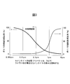
セメンタイトの短径を0.1μm以下としたのは、図3に示す様にマイクロボイド形成段階で隣接したボイドへの連結を生じにくくするためであり、この値を超えると連結しやすくなる。また、さらにセメンタイトの厚みが増して5μm以上になると、セメンタイト自体の割れによるマイクロボイドの形成を招くなど、本発明が問題にしている破壊モードとは別の悪影響が現れる。従って、セメンタイトの短径を0.1μm以下に規定した。
線材製造段階で生じる冷却速度の断面内部位別の差により組織変動が生じるため、全断面を均一組織にするのは自ずと限界があり、ラメラー形態の組織比率を0とすることは困難である。種々試験を行った結果、ラメラー形態の組織比率が5%未満であれば加工性への影響が出にくいことが確認できたため、ラメラー形態の組織比率の上限を5%に規定した。
<鋼片の加熱及び線材圧延工程>
鋼片は950℃~1080℃の範囲で加熱し、加熱後の鋼片を線材圧延する。950℃未満とすると、通常の保定時間内では鋼片の内部偏熱が大きくなり、圧延時の鋼材のそりや反力増大に伴う問題が生じる。また、上限温度を1080℃としたのは、これ以上の加熱温度とすると、γ(オーステナイト)粒径の増大などが生じ易くなるためである。この様な必要以上のγ粒径の増大は、最終製品の表面自由面の肌品質に影響を与えるため上限を1080℃とした。
前記加熱工程後の鋼片に対して、750℃~900℃の範囲にて捲取り工程を行う。下限温度は線材圧延の線径により多少の変動はあるものの、捲取り後の熱処理を安定的に行うために750℃とした。また、750℃以下では熱処理前にパーライト変態が生じて、狙いとする金属組織の付与ができなくなるためである。一方、900℃を超える温度での捲取りは、表面酸化の増大等を招き、好ましくない。
インライン熱処理は、硝酸カリウム及び硝酸ナトリウムの少なくともいずれかの溶融塩が400℃~430℃にて所定の流速で攪拌された冷却槽中に、前記捲取り工程後の線材を浸漬することによって行われる。
インライン熱処理温度の下限温度を400℃としたのは、これ未満の温度では下部ベイナイト組織となって素地の硬さが急激に増えてしまうため、圧造工程等で使用する工具の寿命が劣化するためである。熱処理の上限温度を430℃としたのは、これを超える温度になると上部ベイナイトの中に疑似パーライト組織が混入する領域になるため、セメンタイトのアスペクト比を制御することが困難となり、本発明の最も重要なマイクロボイド形成遅延効果が発揮できなくなるためである。
前記インライン熱処理において、鋼線材はルーズコイル等のコイルの形態で冷却槽内に浸漬される。この場合、冷却槽内の溶融塩の流れを一定の方向に維持したとしても、熱処理される鋼線材がコイル状であるために、溶融塩の鋼線材への衝突方向は場所によって異なり一定の衝突方向とすることは事実上困難と考えられる。
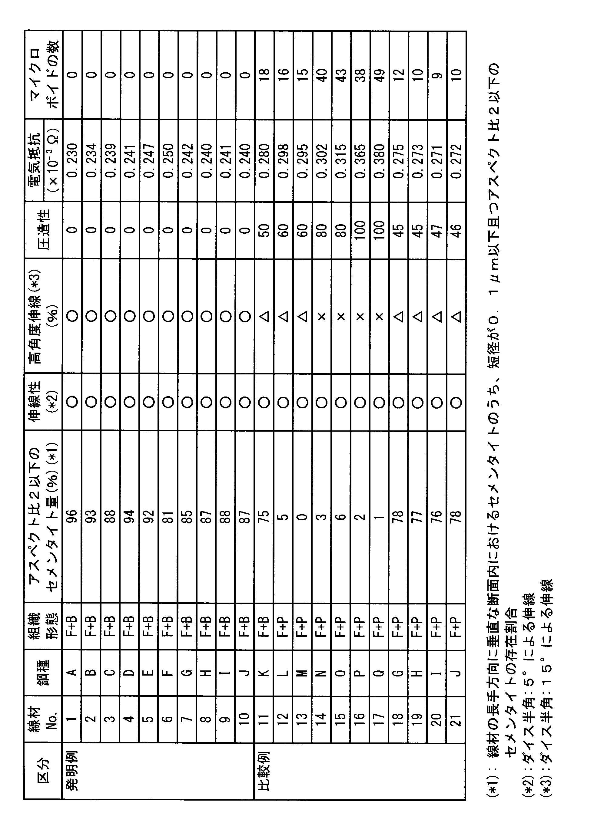
一方、ダイス半角15°の金型を用いた伸線性の試験結果について、鋼線材No.1~10(発明例)と鋼線材No.11~21(比較例)とを比較すると、本発明例の鋼線材は、マイクロボイド生成遅延による高延性を有している。
このことから、マイクロボイド生成遅延による高延性は、アスペクト比の平均値が2以下でその存在比率が80%以上の領域において発現することが判る。
Claims (3)
- 質量%で、C:0.20~0.60%、Si:0.15~0.30%、Mn:0.25~0.60%、P:≦0.020%、S:≦0.010%を含有し、残部Feおよび不可避的不純物である鋼成分を有する鋼線材であって、内部組織としてセメンタイトを有し、線材の長手方向に垂直な断面内におけるセメンタイトのうち、その個数比で80%以上は、短径が0.1μm以下、且つ長径と短径の比からなるアスペクト比が2.0以下であることを特徴とする良加工性鋼線材。
- 前記鋼成分に加えて、更に、質量%で、Al:0.06%以下、Cr:1.5%以下、Mo:0.50%以下、Ni:1.00%以下、V:0.50%以下、B:0.005%以下、Ti:0.05%以下のうち1種以上を含むことを特徴とする請求項1に良加工性鋼線材。
- 請求項1又は請求項2に記載の成分組成の鋼片を950℃~1080℃に加熱して線材圧延に供し、750℃~900℃の温度域で捲取り、その後、400℃~430℃の溶融塩にてインライン熱処理を施し、溶融塩に浸漬中の線材に対して撹拌流速が0.5m/s~2.0m/sの範囲で溶融塩を噴流させることを特徴とする伸線加工性および圧造加工性の優れた良加工性鋼線材の製造方法。
Priority Applications (7)
| Application Number | Priority Date | Filing Date | Title |
|---|---|---|---|
| KR1020167021146A KR101817887B1 (ko) | 2014-03-20 | 2015-03-20 | 양호 가공성 강선재 및 그 제조 방법 |
| EP15765596.0A EP3121305B1 (en) | 2014-03-20 | 2015-03-20 | Excellent workable steel wire rod and method for producing same |
| JP2016508829A JP6245349B2 (ja) | 2014-03-20 | 2015-03-20 | 良加工性鋼線材およびその製造方法 |
| MX2016011928A MX2016011928A (es) | 2014-03-20 | 2015-03-20 | Alambre de acero maquinable de forma favorable y metodo para producirlo. |
| US15/127,142 US10221464B2 (en) | 2014-03-20 | 2015-03-20 | Excellent workability steel wire rod and method for production of same |
| CN201580004308.6A CN105899705B (zh) | 2014-03-20 | 2015-03-20 | 良加工性钢线材及其制造方法 |
| ES15765596T ES2779403T3 (es) | 2014-03-20 | 2015-03-20 | Alambrón de acero maleable excelente y método para producir el mismo |
Applications Claiming Priority (2)
| Application Number | Priority Date | Filing Date | Title |
|---|---|---|---|
| JP2014-058420 | 2014-03-20 | ||
| JP2014058420 | 2014-03-20 |
Publications (1)
| Publication Number | Publication Date |
|---|---|
| WO2015141840A1 true WO2015141840A1 (ja) | 2015-09-24 |
Family
ID=54144801
Family Applications (1)
| Application Number | Title | Priority Date | Filing Date |
|---|---|---|---|
| PCT/JP2015/058566 Ceased WO2015141840A1 (ja) | 2014-03-20 | 2015-03-20 | 良加工性鋼線材およびその製造方法 |
Country Status (8)
| Country | Link |
|---|---|
| US (1) | US10221464B2 (ja) |
| EP (1) | EP3121305B1 (ja) |
| JP (1) | JP6245349B2 (ja) |
| KR (1) | KR101817887B1 (ja) |
| CN (1) | CN105899705B (ja) |
| ES (1) | ES2779403T3 (ja) |
| MX (1) | MX2016011928A (ja) |
| WO (1) | WO2015141840A1 (ja) |
Cited By (1)
| Publication number | Priority date | Publication date | Assignee | Title |
|---|---|---|---|---|
| WO2025069708A1 (ja) * | 2023-09-29 | 2025-04-03 | Jfeスチール株式会社 | 条鋼 |
Families Citing this family (10)
| Publication number | Priority date | Publication date | Assignee | Title |
|---|---|---|---|---|
| CN108754091B (zh) * | 2018-06-14 | 2019-12-20 | 马鞍山钢铁股份有限公司 | 薄带钢快速连续加热用高温熔盐及其加热方法 |
| CN108660297B (zh) * | 2018-06-14 | 2020-02-07 | 马鞍山钢铁股份有限公司 | 电工钢退火线导电式加热方法及其加热循环系统 |
| CN108588355B (zh) * | 2018-06-14 | 2020-04-07 | 马鞍山钢铁股份有限公司 | 电工钢连续退火快速加热方法及其循环加热输送系统 |
| CN108456766B (zh) * | 2018-06-14 | 2019-12-20 | 马鞍山钢铁股份有限公司 | 薄带钢快速连续加热用氯化铝系熔盐及其加热方法 |
| CN108715925B (zh) * | 2018-06-14 | 2019-12-20 | 马鞍山钢铁股份有限公司 | 薄带钢快速连续加热用氯化钠系熔盐及其加热方法 |
| KR102292524B1 (ko) * | 2019-12-17 | 2021-08-24 | 주식회사 포스코 | 냉간가공성이 우수한 선재 및 그 제조방법 |
| KR102347917B1 (ko) * | 2019-12-20 | 2022-01-06 | 주식회사 포스코 | 냉간 가공성이 향상된 선재 및 그 제조방법 |
| CN112501498A (zh) * | 2020-10-20 | 2021-03-16 | 江苏省沙钢钢铁研究院有限公司 | 一种2300MPa预应力钢绞线用盘条及其生产方法 |
| CN112410515A (zh) * | 2020-11-02 | 2021-02-26 | 桃江富硕精密机械有限公司 | 一种高强度耐磨导轨钢的加工工艺 |
| CN120366554B (zh) * | 2025-06-27 | 2025-09-23 | 江苏永钢集团有限公司 | 一种1200MPa级高强度工具钢盘条及其制造方法 |
Citations (6)
| Publication number | Priority date | Publication date | Assignee | Title |
|---|---|---|---|---|
| JP2004100038A (ja) * | 2002-07-16 | 2004-04-02 | Jfe Steel Kk | 熱間圧延ままで球状化組織を有する低合金鋼材及びその製造方法 |
| JP2006316291A (ja) * | 2005-05-10 | 2006-11-24 | Nippon Steel Corp | 冷間鍛造性に優れた鋼線及びその製造方法 |
| JP2007211308A (ja) * | 2006-02-10 | 2007-08-23 | Nippon Steel Corp | 鋼線材のインライン熱処理方法及びインライン熱処理装置 |
| JP2009275250A (ja) * | 2008-05-13 | 2009-11-26 | Nippon Steel Corp | 冷間加工性に優れた鋼線材およびその製造方法 |
| WO2011062012A1 (ja) * | 2009-11-17 | 2011-05-26 | 新日本製鐵株式会社 | 低温焼鈍用鋼線及びその製造方法 |
| JP2012140674A (ja) * | 2010-12-28 | 2012-07-26 | Kobe Steel Ltd | 冷間鍛造性に優れた鋼材、及びその製造方法 |
Family Cites Families (12)
| Publication number | Priority date | Publication date | Assignee | Title |
|---|---|---|---|---|
| JP3380032B2 (ja) | 1994-03-18 | 2003-02-24 | 新日本製鐵株式会社 | 優れた伸線加工性を有する高張力鋼線の製造方法 |
| JPH08295994A (ja) * | 1995-04-21 | 1996-11-12 | Nippon Steel Corp | デスケーリング用線材 |
| JP2000001751A (ja) * | 1998-04-15 | 2000-01-07 | Nippon Steel Corp | 耐断線性の高強度鋼線 |
| US6475306B1 (en) * | 2001-04-10 | 2002-11-05 | Nippon Steel Corporation | Hot rolled steel wire rod or bar for machine structural use and method for producing the same |
| JP3783666B2 (ja) | 2002-08-05 | 2006-06-07 | Jfeスチール株式会社 | 球状化焼鈍後の冷間鍛造性に優れた機械構造用鋼及びその製造方法 |
| TWI318645B (en) | 2005-02-16 | 2009-12-21 | Nippon Steel Corp | Hot rolled steel wire material having superior processability for cold forgine after spheroidization, spheroidized steel wire having superior processability for cold forgine and methods for manufacturing the same |
| JP4669300B2 (ja) | 2005-02-16 | 2011-04-13 | 新日本製鐵株式会社 | 球状化処理後の冷間鍛造性に優れた鋼線材及びその製造方法 |
| JP4903915B2 (ja) * | 2010-01-26 | 2012-03-28 | 新日本製鐵株式会社 | 高強度冷延鋼板及びその製造方法 |
| JP5521885B2 (ja) * | 2010-08-17 | 2014-06-18 | 新日鐵住金株式会社 | 高強度かつ耐水素脆化特性に優れた機械部品用鋼線、および機械部品とその製造方法 |
| JP5425736B2 (ja) * | 2010-09-15 | 2014-02-26 | 株式会社神戸製鋼所 | 冷間加工性、耐摩耗性、及び転動疲労特性に優れた軸受用鋼 |
| KR101488120B1 (ko) * | 2011-02-10 | 2015-01-29 | 신닛테츠스미킨 카부시키카이샤 | 침탄용 강, 침탄강 부품 및 그 제조 방법 |
| WO2014199919A1 (ja) * | 2013-06-13 | 2014-12-18 | 新日鐵住金株式会社 | 引張強さが950~1600MPaであるパーライト組織ボルト用の鋼線の製造用の線材、引張強さが950~1600MPaであるパーライト組織ボルト用の鋼線、パーライト組織ボルト、及び、それらの製造方法 |
-
2015
- 2015-03-20 CN CN201580004308.6A patent/CN105899705B/zh active Active
- 2015-03-20 US US15/127,142 patent/US10221464B2/en not_active Expired - Fee Related
- 2015-03-20 JP JP2016508829A patent/JP6245349B2/ja active Active
- 2015-03-20 EP EP15765596.0A patent/EP3121305B1/en active Active
- 2015-03-20 MX MX2016011928A patent/MX2016011928A/es unknown
- 2015-03-20 WO PCT/JP2015/058566 patent/WO2015141840A1/ja not_active Ceased
- 2015-03-20 KR KR1020167021146A patent/KR101817887B1/ko active Active
- 2015-03-20 ES ES15765596T patent/ES2779403T3/es active Active
Patent Citations (6)
| Publication number | Priority date | Publication date | Assignee | Title |
|---|---|---|---|---|
| JP2004100038A (ja) * | 2002-07-16 | 2004-04-02 | Jfe Steel Kk | 熱間圧延ままで球状化組織を有する低合金鋼材及びその製造方法 |
| JP2006316291A (ja) * | 2005-05-10 | 2006-11-24 | Nippon Steel Corp | 冷間鍛造性に優れた鋼線及びその製造方法 |
| JP2007211308A (ja) * | 2006-02-10 | 2007-08-23 | Nippon Steel Corp | 鋼線材のインライン熱処理方法及びインライン熱処理装置 |
| JP2009275250A (ja) * | 2008-05-13 | 2009-11-26 | Nippon Steel Corp | 冷間加工性に優れた鋼線材およびその製造方法 |
| WO2011062012A1 (ja) * | 2009-11-17 | 2011-05-26 | 新日本製鐵株式会社 | 低温焼鈍用鋼線及びその製造方法 |
| JP2012140674A (ja) * | 2010-12-28 | 2012-07-26 | Kobe Steel Ltd | 冷間鍛造性に優れた鋼材、及びその製造方法 |
Cited By (2)
| Publication number | Priority date | Publication date | Assignee | Title |
|---|---|---|---|---|
| WO2025069708A1 (ja) * | 2023-09-29 | 2025-04-03 | Jfeスチール株式会社 | 条鋼 |
| JPWO2025069708A1 (ja) * | 2023-09-29 | 2025-04-03 |
Also Published As
| Publication number | Publication date |
|---|---|
| EP3121305B1 (en) | 2020-03-11 |
| ES2779403T3 (es) | 2020-08-17 |
| EP3121305A4 (en) | 2017-09-20 |
| MX2016011928A (es) | 2016-12-09 |
| KR101817887B1 (ko) | 2018-01-11 |
| EP3121305A1 (en) | 2017-01-25 |
| US10221464B2 (en) | 2019-03-05 |
| KR20160105862A (ko) | 2016-09-07 |
| US20170101696A1 (en) | 2017-04-13 |
| JP6245349B2 (ja) | 2017-12-13 |
| JPWO2015141840A1 (ja) | 2017-04-13 |
| CN105899705A (zh) | 2016-08-24 |
| CN105899705B (zh) | 2017-12-08 |
Similar Documents
| Publication | Publication Date | Title |
|---|---|---|
| JP6245349B2 (ja) | 良加工性鋼線材およびその製造方法 | |
| JP6031022B2 (ja) | 耐遅れ破壊性に優れたボルト用鋼線および高強度ボルト並びにそれらの製造方法 | |
| WO2016194272A1 (ja) | 高強度冷延鋼板、高強度めっき鋼板及びこれらの製造方法 | |
| JP6384626B2 (ja) | 高周波焼入れ用鋼 | |
| JP5913214B2 (ja) | ボルト用鋼およびボルト、並びにそれらの製造方法 | |
| JP6384629B2 (ja) | 高周波焼入れ用鋼 | |
| JP6725007B2 (ja) | 線材 | |
| JP6384630B2 (ja) | 高周波焼入れ用鋼 | |
| JP6384627B2 (ja) | 高周波焼入れ用鋼 | |
| WO2015098531A1 (ja) | 高強度ばね用圧延材及びこれを用いた高強度ばね用ワイヤ | |
| JPH06306543A (ja) | 耐遅れ破壊特性に優れた高強度pc棒線とその製造方法 | |
| JP2011214058A (ja) | 高強度ステンレス鋼線及びその製造方法 | |
| CN111886354B (zh) | 具有优异的延性和扩孔性的高强度钢板 | |
| JP6206423B2 (ja) | 低温靭性に優れた高強度ステンレス厚鋼板およびその製造方法 | |
| JP6059676B2 (ja) | 非調質ウェルドボルト用鋼材およびその製造方法 | |
| WO2017094487A1 (ja) | 高強度ボルト | |
| JP5653269B2 (ja) | 耐食性、強度、及び延性に優れるステンレス鋼線材と鋼線、並びに、それらの製造方法。 | |
| JP4867638B2 (ja) | 耐遅れ破壊特性および耐腐食性に優れた高強度ボルト | |
| CN107429359B (zh) | 热轧棒线材、部件及热轧棒线材的制造方法 | |
| TWI886802B (zh) | 螺栓及螺栓製造方法 | |
| JP4301686B2 (ja) | 熱処理時の粗粒化特性および冷間加工性に優れたオーステナイト系ステンレス鋼線材 | |
| JP5633426B2 (ja) | 熱処理用鋼材 | |
| JP2008274344A (ja) | 耐遅れ破壊特性および疲労特性に優れた高強度鋼管 | |
| CN107002202A (zh) | 线材 |
Legal Events
| Date | Code | Title | Description |
|---|---|---|---|
| 121 | Ep: the epo has been informed by wipo that ep was designated in this application |
Ref document number: 15765596 Country of ref document: EP Kind code of ref document: A1 |
|
| ENP | Entry into the national phase |
Ref document number: 20167021146 Country of ref document: KR Kind code of ref document: A |
|
| ENP | Entry into the national phase |
Ref document number: 2016508829 Country of ref document: JP Kind code of ref document: A |
|
| WWE | Wipo information: entry into national phase |
Ref document number: MX/A/2016/011928 Country of ref document: MX |
|
| WWE | Wipo information: entry into national phase |
Ref document number: 15127142 Country of ref document: US |
|
| NENP | Non-entry into the national phase |
Ref country code: DE |
|
| REEP | Request for entry into the european phase |
Ref document number: 2015765596 Country of ref document: EP |
|
| WWE | Wipo information: entry into national phase |
Ref document number: 2015765596 Country of ref document: EP |
|
| WWE | Wipo information: entry into national phase |
Ref document number: IDP00201606977 Country of ref document: ID |