WO2015145621A1 - Corps d'emballage - Google Patents
Corps d'emballage Download PDFInfo
- Publication number
- WO2015145621A1 WO2015145621A1 PCT/JP2014/058568 JP2014058568W WO2015145621A1 WO 2015145621 A1 WO2015145621 A1 WO 2015145621A1 JP 2014058568 W JP2014058568 W JP 2014058568W WO 2015145621 A1 WO2015145621 A1 WO 2015145621A1
- Authority
- WO
- WIPO (PCT)
- Prior art keywords
- support
- support member
- fixing
- plate
- disposed
- Prior art date
- Legal status (The legal status is an assumption and is not a legal conclusion. Google has not performed a legal analysis and makes no representation as to the accuracy of the status listed.)
- Ceased
Links
Images





Classifications
-
- B—PERFORMING OPERATIONS; TRANSPORTING
- B65—CONVEYING; PACKING; STORING; HANDLING THIN OR FILAMENTARY MATERIAL
- B65D—CONTAINERS FOR STORAGE OR TRANSPORT OF ARTICLES OR MATERIALS, e.g. BAGS, BARRELS, BOTTLES, BOXES, CANS, CARTONS, CRATES, DRUMS, JARS, TANKS, HOPPERS, FORWARDING CONTAINERS; ACCESSORIES, CLOSURES, OR FITTINGS THEREFOR; PACKAGING ELEMENTS; PACKAGES
- B65D5/00—Rigid or semi-rigid containers of polygonal cross-section, e.g. boxes, cartons or trays, formed by folding or erecting one or more blanks made of paper
- B65D5/42—Details of containers or of foldable or erectable container blanks
- B65D5/44—Integral, inserted or attached portions forming internal or external fittings
- B65D5/50—Internal supporting or protecting elements for contents
- B65D5/5028—Elements formed separately from the container body
- B65D5/5035—Paper elements
- B65D5/5059—Paper panels presenting one or more openings or recesses in wich at least a part of the contents are located
-
- B—PERFORMING OPERATIONS; TRANSPORTING
- B65—CONVEYING; PACKING; STORING; HANDLING THIN OR FILAMENTARY MATERIAL
- B65D—CONTAINERS FOR STORAGE OR TRANSPORT OF ARTICLES OR MATERIALS, e.g. BAGS, BARRELS, BOTTLES, BOXES, CANS, CARTONS, CRATES, DRUMS, JARS, TANKS, HOPPERS, FORWARDING CONTAINERS; ACCESSORIES, CLOSURES, OR FITTINGS THEREFOR; PACKAGING ELEMENTS; PACKAGES
- B65D5/00—Rigid or semi-rigid containers of polygonal cross-section, e.g. boxes, cartons or trays, formed by folding or erecting one or more blanks made of paper
- B65D5/42—Details of containers or of foldable or erectable container blanks
- B65D5/44—Integral, inserted or attached portions forming internal or external fittings
- B65D5/48—Partitions
- B65D5/48024—Partitions inserted
- B65D5/48026—Squaring or like elements, e.g. honeycomb element, i.e. at least four not aligned compartments
- B65D5/48038—Strips crossing each other
Definitions
- This invention relates to a packing body for packing parts.
- Patent Document 1 describes the prior art of a package.
- the package described in Patent Document 1 packs a component in which a metal foil is wound around a shaft. In this part, both ends of the shaft are supported from above and below inside the package.
- An object of the present invention is to provide a package that can prevent parts from being deformed by vibration during transportation.
- a packaging body includes a fixing material in which a plurality of through holes are formed, a first support material that is disposed on the fixing material and has a plurality of first spaces that are opened up and down, and a fixing material.
- a second support member disposed below and formed with a plurality of second spaces opening up and down; and a plate member disposed below the second support member, wherein the first space is provided in each of the through holes. Arranged above, the second space is arranged below each of the through holes.
- the packing body according to the present invention is a packing body for packing a part having an upper portion protruding from the upper surface of the central portion and a lower portion protruding from the lower surface of the central portion, and a fixing material in which a through hole is formed,
- a first support member disposed on the fixing member and exhibiting a lattice shape; a second support member disposed below the fixing member and exhibiting a lattice shape; and a plate member disposed below the second support member.
- the lower part of the component penetrates the through-hole, the lower surface of the central part of the component contacts the upper surface of the fixing material, and the lower surface of the lower part of the component faces the upper surface of the plate member with a gap.
- the package according to the present invention can prevent the parts from being deformed by vibration during transportation.
- Embodiment 1 of this invention It is a disassembled perspective view of the package in Embodiment 1 of this invention. It is a perspective view which shows the components packed with a package. It is a perspective view which shows a fixing material. It is a perspective view which shows the support material arrange
- FIG. 1 is an exploded perspective view of a packing body according to Embodiment 1 of the present invention.
- FIG. 1 shows an example in which 18 parts 1 are packed by one packing body.
- FIG. 2 is a perspective view showing the component 1 to be packed by the packing body.
- the component 1 includes a central portion 2 whose outer shape is a disk shape, and an upper portion 3 and a lower portion 4 whose outer shapes are cylindrical.
- the central part 2 is a part between the upper part 3 and the lower part 4.
- the central axis of the upper part 3 and the central axis of the central part 2 are arranged on the same straight line.
- the diameter of the upper part 3 is smaller than the diameter of the central part 2.
- the central axis of the lower part 4 and the central axis of the central part 2 are arranged on the same straight line.
- the diameter of the lower part 4 is smaller than the diameter of the central part 2.
- the diameter of the lower part 4 is smaller than the diameter of the upper part 3.
- the lower part 4 protrudes downward from the lower surface of the central part 2.
- the upper and lower parts 1 are specified based on the state of being packed by the packing body.
- the direction in which the component 1 is actually used may not coincide with the direction in which it is packed.
- FIG. 1 shows an example in which three parts 1 are arranged in the left-right direction and three parts 1 are arranged in the front-rear direction. In the example shown in FIG. 1, nine parts 1 are supported by one support unit 5. The number of parts 1 supported by one support unit 5 can be freely set as required.
- the package includes one or a plurality of support units 5.
- FIG. 1 shows an example where the support units 5 are arranged in two stages. In the example shown in FIG. 1, 18 parts 1 are packed by one packing body. The number of parts 1 to be packed by the packing body can be freely set as necessary.
- the support unit 5 includes a fixing material 6, a support material 7 (first support material), a support material 8 (second support material), and a plate material 9.
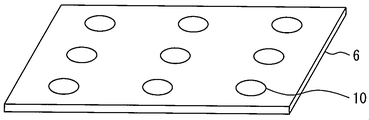
- FIG. 3 is a perspective view showing the fixing member 6.
- the fixing material 6 is a member for fixing the component 1.
- FIG. 3 shows an example in which the fixing member 6 has a rectangular plate shape.
- the external shape of the fixing material 6 is not limited to the example shown in FIG.
- a through hole 10 is formed in the fixing material 6.
- the number of through holes 10 formed in the fixing member 6 is the same as the number of components 1 supported by the support unit 5.
- the number of through holes 10 may be larger than the number of components 1 supported by the support unit 5.
- three through holes 10 are arranged in the left-right direction, and three through holes 10 are arranged in the front-rear direction. That is, nine through holes 10 are regularly arranged in the fixing member 6.
- the diameter of the through hole 10 is almost the same as the diameter of the lower part 4 of the component 1.
- the diameter of the through hole 10 may be slightly smaller than the diameter of the lower portion 4 of the component 1.
- the fixing member 6 is arranged so that the through hole 10 opens up and down.
- FIG. 4 is a perspective view showing the support member 7 disposed on the upper side.
- the support member 7 is disposed on the fixing member 6.
- the upper and lower ends of the support member 7 are flat.
- a plurality of spaces 11 (first spaces) having a quadrangular prism shape are formed in the support member 7.
- the space 11 is opened up and down, and is surrounded by members constituting the support member 7.
- the space 11 is disposed immediately above the through hole 10. In other words, the members constituting the support member 7 are not arranged immediately above the through holes 10.
- the space 11 is disposed above each of the through holes 10.
- FIG. 4 shows an example in which the support material 7 has a lattice shape.
- the support material 7 has a lattice shape.
- three spaces 11 are arranged in the left-right direction, and three spaces 11 are arranged in the front-rear direction.
- the support member 7 has a cross beam structure, and nine spaces 11 are regularly arranged in the support member 7.
- the support material 7 is formed in a lattice shape by combining a plurality of plate-like members, for example. In this case, a space surrounded by the four plate-like members becomes the space 11.
- the plate-like member constituting the support member 7 is arranged vertically so that the end surface on the long side faces up and down.
- the support member 7 is formed in a lattice shape by combining a plurality of square tubular members. In this case, the space formed inside the rectangular tubular member becomes the space 11.
- the rectangular tubular member constituting the support member 7 is formed from, for example, a plate-like member. The rectangular tubular member is arranged so that the end surface on the long side of the plate-shaped member faces up and down.
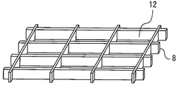
- FIG. 5 is a perspective view showing the support member 8 disposed on the lower side.
- the support member 8 is disposed under the fixing member 6.
- the upper end and the lower end of the support material 8 are flat.
- a plurality of spaces 12 (second spaces) having a quadrangular prism shape are formed in the support material 8.
- the space 12 is opened up and down, and is surrounded by members constituting the support member 8.
- the space 12 is disposed immediately below the through hole 10. That is, the members constituting the support material 8 are not arranged directly below the through holes 10.
- the space 12 is disposed below each of the through holes 10.
- FIG. 5 shows an example in which the support material 8 has a lattice shape.
- the support material 8 has a lattice shape.
- three spaces 12 are arranged in the left-right direction, and three spaces 12 are arranged in the front-rear direction.
- the support member 8 has a cross-girder structure, and nine spaces 12 are regularly arranged in the support member 8.
- the support material 8 is formed in a lattice shape by combining a plurality of plate-like members, for example. In this case, the space surrounded by the four plate-like members becomes the space 12.
- the plate-like member constituting the support member 8 is arranged vertically so that the end surface on the long side faces up and down.
- the support member 8 is formed in a lattice shape by combining a plurality of square tubular members. In this case, the space formed inside the rectangular tubular member becomes the space 12.
- the rectangular tubular member constituting the support member 8 is formed from, for example, a plate-like member. The rectangular tubular member is arranged so that the end surface on the long side of the plate-shaped member faces up and down.
- the plate material 9 is disposed at the bottom of the support unit 5. That is, the plate material 9 is disposed under the support material 8.
- FIG. 1 shows an example in which the plate 9 has a quadrangular shape.
- the outer diameter size of the plate material 9 is the same as the outer diameter size of the fixing material 6.
- the members constituting the support unit 5 are preferably formed from a paper material such as cardboard.
- the material of the members constituting the support unit 5 is not limited to paper. All or part of the members constituting the support unit 5 may be formed of a material other than paper.
- FIG. 1 shows, as an example, a case where the support units 5 stacked in two stages are covered with exterior materials 13, 14, and 15.
- the exterior material 13 covers the lower part of the support unit 5 from below.
- the lower part of the support unit 5 arranged at the bottom is covered with the exterior material 13.
- the exterior material 15 covers the upper part of the support unit 5 from above.
- the upper part of the support unit 5 arranged at the top is covered with the exterior material 15.
- the exterior material 14 covers the support unit 5 from the side.
- FIG. 1 shows an example in which an outer box is formed by the exterior materials 13 and 14.
- the outer box is opened at the top and accommodates all or part of the support unit 5 inside.
- the exterior material 15 serves as a lid for the outer box.
- the exterior material 15 covers the exterior material 14 (outer box) from above.
- the lower end of the exterior material 15 is disposed below the upper end of the exterior material 14 (outer box).
- the members constituting the outer box and the lid are preferably formed from a paper material such as cardboard.
- the material of the members constituting the outer box and the lid is not limited to paper. All or a part of the members constituting the outer box and the lid may be formed of a material other than paper.
- the procedure for packing the component 1 will be described with reference to FIGS.
- the exterior material 13 is placed on a floor or a table.
- the exterior material 14 is erected on the exterior material 13 so that the lower end of the exterior material 14 is disposed inside the edge portion of the exterior material 13.
- an outer box is formed by the exterior members 13 and 14.
- the plate material 9, the support material 8, the fixing material 6, and the support material 7 are installed in order from the bottom. Specifically, first, the plate material 9 is laid on the bottom of the outer box. Next, the support material 8 is placed on the plate material 9.
- the gap between the support material 8 and the outer box when the support material 8 is placed on the plate 9 in the outer box is preferably small.
- the difference between the outer dimension in the left-right direction of the support member 8 and the inner dimension in the left-right direction of the outer box is smaller than the thickness of the plate-like member constituting the support member 8.
- the difference between the outer dimension in the front-rear direction of the support member 8 and the inner dimension in the front-rear direction of the outer box is preferably smaller than the thickness of the plate-like member constituting the support member 8.
- the fixing material 6 is placed on the support material 8.
- the fixing member 6 is formed so that the outer dimension thereof matches the inner dimension of the outer box.
- the through hole 10 is formed in the fixing material 6 according to the arrangement of the space 12.
- the gap between the support material 7 and the outer box when the support material 7 is placed on the fixing material 6 in the outer box is preferably small.
- the difference between the outer dimension in the left-right direction of the support member 7 and the inner dimension in the left-right direction of the outer box is preferably smaller than the thickness of the plate-like member constituting the support member 7.
- the difference between the outer dimension in the front-rear direction of the support member 7 and the inner dimension in the front-rear direction of the outer box is smaller than the thickness of the plate-like member constituting the support member 7.
- the shape of the support material 7 when viewed from above matches the shape when the support material 8 is viewed from above. For this reason, the space 11 is disposed immediately above the space 12 with the fixing member 6 interposed therebetween. Further, when the support member 7 is placed on the fixing member 6 in the outer box, the through hole 10 is disposed immediately below the space 11.
- the parts 1 are stored in each storage place formed in the outer box.
- a space formed by the space 12, the through hole 10, and the space 11 connected in the vertical direction is a storage place for the component 1.
- the component 1 is inserted into the space 11 from above, and the lower portion 4 of the component 1 is fitted into the through hole 10.
- the components 1 are stored in all the storage locations formed in the support unit 5 for one stage.
- FIG. 6 is a cross-sectional view showing a state in which the component 1 is properly stored in the storage place.
- the component 1 has a central portion 2 placed on a fixing material 6.
- the lower surface of the central portion 2 is in contact with the upper surface of the fixing material 6.
- the lower portion 4 penetrates the through hole 10.
- the lower portion 4 is disposed in the through hole 10 and the space 12.
- the lower portion 4 does not contact the support material 8 and the plate material 9.
- the sum of the thickness (height) of the fixing member 6 and the height of the support member 8 is larger than the height of the lower portion 4.
- the lower part 4 is arrange
- the lower surface of the lower portion 4 faces the upper surface of the plate member 9 with a gap.
- the central part 2 and the upper part 3 of the part 1 are arranged in the space 11.
- the central part 2 does not contact the support material 7.
- the upper portion 3 does not contact the fixing material 6 and the support material 7.
- the height of the support member 7 is larger than the sum of the thickness (height) of the central portion 2 and the height of the upper portion 3. For this reason, the upper end of the upper part 3 is disposed below the upper end of the support member 7.
- the plate material 9 is placed on the support material 7 disposed at the top of the outer box. Then, the support member 8, the fixing member 6, and the support member 7 are placed on the plate member 9 in order. Finally, the component 1 is stored in a newly formed storage place.
- FIG. 7 is a diagram for explaining the packaging process of the part 1.
- FIG. 7 shows a state in which the parts 1 are stored in all the storage locations.
- the uppermost support unit 5 the upper end of the support member 7 is disposed above the upper end of the outer box.
- Support units 5 other than the uppermost support unit 5 are arranged inside the outer box.
- plate material 9, the support material 8, and the fixing material 6 among the uppermost support units 5 are arrange
- FIG. 8 is a perspective view showing a state where the packaging of the component 1 is completed.
- the components 1 can be fixed appropriately. Since the lower part 4 of the component 1 is fitted in the through hole 10, the position in the left-right direction and the front-rear direction is restricted by the fixing material 6. Further, even if a diagonally upward force is applied to the component 1, the component 1 does not easily come off the fixing material 6. Therefore, the component 1 does not move greatly due to vibration and impact during transportation, and the component 1 can be prevented from being scratched.
- transformation of the components 1 can be prevented.
- the central portion 2 having the largest diameter is supported from below by a fixing material 6.
- the part where the component 1 contacts the fixing member 6 is arranged around the central axis of the component 1. Therefore, the component 1 can be stably held, and an excessive force can be prevented from acting locally on the component 1 during transportation.
- positioned upward and the load of the other components 1 do not act directly on the components 1. FIG. For this reason, when the package shown in FIG. 8 is stacked and stored in a warehouse or the like, it is possible to prevent the component 1 from being deformed by a compressive load.
- Each of the spaces 12 is partitioned by members constituting the support member 8 and opens only in the vertical direction. Since the plurality of spaces 12 are arranged side by side, the support material 8 contacts the fixing material 6 over the entire lower surface of the fixing material 6. Therefore, it is possible to prevent the load from the fixing material 6 from concentrating locally on the support material 8. Similarly, the support material 8 contacts the plate material 9 over the entire upper surface of the plate material 9. For this reason, the load from the support material 8 can be dispersed throughout the plate material 9.
- the space 11 is partitioned by members constituting the support material 7 and opens only in the vertical direction. Since the plurality of spaces 11 are arranged side by side, the support member 7 contacts the plate member 9 over the entire lower surface of the plate member 9 of the support unit 5 on the upper stage. Therefore, it can prevent that the load from the board
- the uppermost support unit 5 is arranged such that the upper end of the support member 7 is located above the upper end of the outer box. For this reason, when the packaging body is stacked, the packaging body arranged below can support the load of the packaging body arranged above with the uppermost support member 7. It is possible to prevent the exterior material 14 from being crushed or swelled when stored in a warehouse or the like, thereby damaging the appearance. Note that the upper end of the exterior member 14 may be disposed above the upper end of the support member 7 unless a large number of packages are stacked and stored or transported.
- the shape of the component 1 is not limited to the shape described in the present embodiment.
- the outer shape of the central portion 2 may not be circular.
- the diameter of the upper part 3 and the diameter of the lower part 4 may be the same.
- the central part 2 may be thicker than the upper part 3 or the lower part 4.
- a roll component having a boss portion having a diameter smaller than that of the central portion is suitable.
- the shape of the support material 7 is not limited to the shape described in the present embodiment.
- the space 11 may have a columnar shape.
- the space 11 may have a triangular prism shape or a hexagonal prism shape.
- the support material 7 is formed in a honeycomb shape, for example. Even in such a configuration, the support member 7 can be brought into contact over the entire lower surface of the upper plate member 9. Further, the support member 7 can be brought into contact with the entire upper surface of the fixing member 6.
- the support member 7 is formed in a lattice shape, there is an advantage that the spaces 11 can be regularly arranged with a simple configuration. In addition, the support material 7 can be easily manufactured.
- the shape of the support material 8 is not limited to the shape described in the present embodiment.
- the space 12 may have a columnar shape.
- the space 12 may have a triangular prism shape or a hexagonal prism shape.
- the support material 8 is formed in a honeycomb shape, for example. Even with this configuration, the support member 8 can be brought into contact with the entire lower surface of the fixing member 6. Further, the support material 8 can be brought into contact over the entire upper surface of the plate material 9.
- the support material 8 is formed in a lattice shape, there is an advantage that the spaces 12 can be regularly arranged with a simple configuration. In addition, the support material 8 can be easily manufactured.
- the configuration of the support material 8 is preferably the same as the configuration of the support material 7 as shown in FIGS.
- the case where the number of the members which comprise the support material 8 is the same as the number of the members which comprise the support material 7 was shown as an example. Even in such a case, the heights of the support material 7 and the support material 8 are appropriately set according to the shape of the component 1.
- the packing body according to the present invention can be applied when packing parts having protrusions.
Landscapes
- Engineering & Computer Science (AREA)
- Mechanical Engineering (AREA)
- Buffer Packaging (AREA)
- Packages (AREA)
- Packaging Of Annular Or Rod-Shaped Articles, Wearing Apparel, Cassettes, Or The Like (AREA)
- Packaging Of Machine Parts And Wound Products (AREA)
Abstract
L'invention concerne un corps d'emballage doté d'un élément de fixation (6), d'un élément de support (7), d'un élément de support (8) et d'un élément de plaque (9). Des trous traversants (10) sont formés dans l'élément de fixation (6). L'élément de support (7) est disposé sur l'élément de fixation (6). Des espaces (11) ouverts au niveau d'extrémités supérieures et inférieures sont formés dans l'élément de support (7). L'élément de support (8) est disposé sous l'élément de fixation (6). Des espaces (12) ouverts au niveau des extrémités supérieures et inférieures sont formés dans l'élément de support (8). L'élément de plaque (9) est disposé sous l'élément de support (8). Les espaces (11) sont respectivement agencés sur les trous traversants (10). Les espaces (12) sont respectivement agencés sous les trous traversants (10).
Priority Applications (3)
| Application Number | Priority Date | Filing Date | Title |
|---|---|---|---|
| JP2016509714A JP6079928B2 (ja) | 2014-03-26 | 2014-03-26 | 梱包体 |
| PCT/JP2014/058568 WO2015145621A1 (fr) | 2014-03-26 | 2014-03-26 | Corps d'emballage |
| CN201520172588.9U CN204568373U (zh) | 2014-03-26 | 2015-03-25 | 包装体 |
Applications Claiming Priority (1)
| Application Number | Priority Date | Filing Date | Title |
|---|---|---|---|
| PCT/JP2014/058568 WO2015145621A1 (fr) | 2014-03-26 | 2014-03-26 | Corps d'emballage |
Publications (1)
| Publication Number | Publication Date |
|---|---|
| WO2015145621A1 true WO2015145621A1 (fr) | 2015-10-01 |
Family
ID=53861045
Family Applications (1)
| Application Number | Title | Priority Date | Filing Date |
|---|---|---|---|
| PCT/JP2014/058568 Ceased WO2015145621A1 (fr) | 2014-03-26 | 2014-03-26 | Corps d'emballage |
Country Status (3)
| Country | Link |
|---|---|
| JP (1) | JP6079928B2 (fr) |
| CN (1) | CN204568373U (fr) |
| WO (1) | WO2015145621A1 (fr) |
Citations (6)
| Publication number | Priority date | Publication date | Assignee | Title |
|---|---|---|---|---|
| JPS5254381U (fr) * | 1975-10-17 | 1977-04-19 | ||
| JPS61164982A (ja) * | 1985-01-14 | 1986-07-25 | 松下電器産業株式会社 | モ−タの集合包装装置 |
| US4826012A (en) * | 1988-03-23 | 1989-05-02 | Alco Standrad Corporation | Package for fragile articles |
| GB2418413A (en) * | 2004-09-25 | 2006-03-29 | Amsafe Bridport Ltd | Securing goods on pallets |
| JP2010105672A (ja) * | 2008-10-28 | 2010-05-13 | Sanwa System Engineering Kk | 筒状体収納用トレイ |
| JP2013513051A (ja) * | 2009-12-03 | 2013-04-18 | シーメンス アクティエンゲゼルシャフト | 適応性のある輸送パッケージ |
-
2014
- 2014-03-26 WO PCT/JP2014/058568 patent/WO2015145621A1/fr not_active Ceased
- 2014-03-26 JP JP2016509714A patent/JP6079928B2/ja not_active Expired - Fee Related
-
2015
- 2015-03-25 CN CN201520172588.9U patent/CN204568373U/zh not_active Expired - Lifetime
Patent Citations (6)
| Publication number | Priority date | Publication date | Assignee | Title |
|---|---|---|---|---|
| JPS5254381U (fr) * | 1975-10-17 | 1977-04-19 | ||
| JPS61164982A (ja) * | 1985-01-14 | 1986-07-25 | 松下電器産業株式会社 | モ−タの集合包装装置 |
| US4826012A (en) * | 1988-03-23 | 1989-05-02 | Alco Standrad Corporation | Package for fragile articles |
| GB2418413A (en) * | 2004-09-25 | 2006-03-29 | Amsafe Bridport Ltd | Securing goods on pallets |
| JP2010105672A (ja) * | 2008-10-28 | 2010-05-13 | Sanwa System Engineering Kk | 筒状体収納用トレイ |
| JP2013513051A (ja) * | 2009-12-03 | 2013-04-18 | シーメンス アクティエンゲゼルシャフト | 適応性のある輸送パッケージ |
Also Published As
| Publication number | Publication date |
|---|---|
| JP6079928B2 (ja) | 2017-02-15 |
| JPWO2015145621A1 (ja) | 2017-04-13 |
| CN204568373U (zh) | 2015-08-19 |
Similar Documents
| Publication | Publication Date | Title |
|---|---|---|
| CN102424204B (zh) | 用于容纳卷状物的容纳箱 | |
| US20110024324A1 (en) | Suspension / retention packaging | |
| KR20220026553A (ko) | 내용물 완충과 고정을 위한 내부 포장재 및 이의 제작모듈 | |
| JP2008308192A (ja) | 電子部品用包装トレイ | |
| US10358262B2 (en) | Shaft packaging body | |
| WO2018199026A1 (fr) | Plateau d'emballage | |
| JP6079928B2 (ja) | 梱包体 | |
| JP6532226B2 (ja) | 胴枠体及び梱包箱 | |
| JP2010064758A (ja) | ハニカム構造体包装体 | |
| JP2015151184A (ja) | ガラス梱包体、およびガラス梱包体の製造方法 | |
| JP2019127273A (ja) | 緩衝体及び梱包体 | |
| JP5854980B2 (ja) | 感光体ドラムの梱包容器 | |
| JP2014101131A (ja) | 瓶保持体 | |
| JP4420257B1 (ja) | 輸送用パレット、およびロール状物の収納方法 | |
| KR20180136125A (ko) | 벽면체 및 기둥체를 동시에 지지하는 포장박스용 브래킷 | |
| JP2010208666A (ja) | パネル梱包体 | |
| JP6057872B2 (ja) | 包装装置 | |
| JP2009202919A (ja) | 包装ケース | |
| KR101046663B1 (ko) | 평판디스플레이 제품의 포장 박스 | |
| JP2017077321A (ja) | 弁当箱 | |
| JP6287171B2 (ja) | 梱包材及びシート | |
| JP4760817B2 (ja) | 梱包用緩衝装置 | |
| JP5164590B2 (ja) | 物品の宙吊り包装装置 | |
| JP2012254807A (ja) | 板状体梱包容器及びその積層方法 | |
| JP2019123535A (ja) | 梱包箱と梱包方法 |
Legal Events
| Date | Code | Title | Description |
|---|---|---|---|
| 121 | Ep: the epo has been informed by wipo that ep was designated in this application |
Ref document number: 14887366 Country of ref document: EP Kind code of ref document: A1 |
|
| ENP | Entry into the national phase |
Ref document number: 2016509714 Country of ref document: JP Kind code of ref document: A |
|
| NENP | Non-entry into the national phase |
Ref country code: DE |
|
| 122 | Ep: pct application non-entry in european phase |
Ref document number: 14887366 Country of ref document: EP Kind code of ref document: A1 |