WO2015145696A1 - Stator et machine dynamo-électrique contenant celui-ci - Google Patents
Stator et machine dynamo-électrique contenant celui-ci Download PDFInfo
- Publication number
- WO2015145696A1 WO2015145696A1 PCT/JP2014/059022 JP2014059022W WO2015145696A1 WO 2015145696 A1 WO2015145696 A1 WO 2015145696A1 JP 2014059022 W JP2014059022 W JP 2014059022W WO 2015145696 A1 WO2015145696 A1 WO 2015145696A1
- Authority
- WO
- WIPO (PCT)
- Prior art keywords
- segment conductor
- segment
- slot
- phase coil
- stator
- Prior art date
- Legal status (The legal status is an assumption and is not a legal conclusion. Google has not performed a legal analysis and makes no representation as to the accuracy of the status listed.)
- Ceased
Links
Images











Classifications
-
- H—ELECTRICITY
- H02—GENERATION; CONVERSION OR DISTRIBUTION OF ELECTRIC POWER
- H02K—DYNAMO-ELECTRIC MACHINES
- H02K1/00—Details of the magnetic circuit
- H02K1/06—Details of the magnetic circuit characterised by the shape, form or construction
- H02K1/12—Stationary parts of the magnetic circuit
- H02K1/16—Stator cores with slots for windings
-
- H—ELECTRICITY
- H02—GENERATION; CONVERSION OR DISTRIBUTION OF ELECTRIC POWER
- H02K—DYNAMO-ELECTRIC MACHINES
- H02K3/00—Details of windings
- H02K3/04—Windings characterised by the conductor shape, form or construction, e.g. with bar conductors
- H02K3/12—Windings characterised by the conductor shape, form or construction, e.g. with bar conductors arranged in slots
-
- H—ELECTRICITY
- H02—GENERATION; CONVERSION OR DISTRIBUTION OF ELECTRIC POWER
- H02K—DYNAMO-ELECTRIC MACHINES
- H02K3/00—Details of windings
- H02K3/04—Windings characterised by the conductor shape, form or construction, e.g. with bar conductors
- H02K3/28—Layout of windings or of connections between windings
Definitions
- the present invention relates to a stator and a rotating electrical machine including the stator.
- the conventional method for manufacturing a rotating electrical machine and the rotating electrical machine have the following problems.
- the conventional rotating electric machine described above in order to ensure sufficient bonding strength, the end portions of the segment conductors are compressed after the U-shaped segment conductors are inserted into the slots. In such a case, it is difficult to perform compression.
- a stator according to a first invention includes a stator core and a coil.
- the stator core has a cylindrical shape and has a plurality of slots formed along the radial direction on the inside thereof.
- the coil has a plurality of segment conductors arranged in the slot, and the end portions of the segment conductors are joined to each other.
- the segment conductor has a rectangular cross section, is formed by a rectangular wire having a first surface having a wide width and a second surface having a small width, and is disposed in the slot so that the first surface is parallel to the radial direction. ing.
- a plurality of segment conductors are arranged so that the second surfaces of the slots face each other.
- the segment conductor arranged i-th (i is an integer equal to or greater than 1) from the inside of the stator core is opposed to the segment conductor arranged i + 1 in the other slot, and the first surfaces thereof are opposed to each other at the end portions. Are joined together.
- the joined first surfaces are formed in parallel with the radial direction.
- Parallel in this specification does not mean only parallel in a strict sense. Since variations occur due to machining, bending, and assembly of the component parts, they do not necessarily fall within the accuracy defined by geometry, but in the present application, they are described as being parallel.
- the segment conductors are joined by the wide first surfaces, even if welding is performed without compressing the end portions of the segment conductors, sufficient joining strength can be ensured. Since it is not necessary to compress the end portions of the segment conductors, it is possible to provide a stator that can ensure sufficient bonding strength even if the portions to be joined are dense. In addition, in order to obtain strength and conductivity, it is necessary to secure the same cross-sectional area as the segment conductor, but since the first surfaces having a wide width are opposed to each other, the joining depth is set to be reduced. The height of the coil end portion can be suppressed by securing the width of the second surface.
- a stator according to a second invention is the stator according to the first invention, wherein the end of the i-th segment conductor faces the end of the i + 1-th segment conductor so that the second surface is curved. It is bent outward and joined to the end of the (i + 1) th segment conductor.
- the joined 1st surface is formed near the outer side of the stator core.
- the positions of the end portions of the segment conductors to be joined are located on the outer side of the stator core.
- the circumferential direction of the two end portions arranged opposite to each other A wedge-shaped welding electrode is inserted to the outside from the outer peripheral side of the stator.
- the positions of the two end portions to be joined are located closer to the outer side of the stator core, the interval between the positions to be joined adjacent to each other in the circumferential direction becomes wider. Since it is not necessary to make it extremely thin, manufacture of a welding electrode becomes easy.
- a stator according to a third aspect of the present invention is the stator according to the first or second aspect of the present invention, wherein the opposing first surfaces are the slot side where the i + 1th segment conductor of the ith segment conductor is disposed. And the first surface on the slot side where the i-th segment conductor of the (i + 1) -th segment conductor is disposed. Thereby, it becomes possible to join the segment conductors at a short distance.
- a stator according to a fourth invention is the stator according to the second invention, wherein a step is formed on the first surface so that the width of the second surface is narrowed at the end of the i-th segment conductor. Yes.
- the step surface formed perpendicular to the first surface by the step is disposed perpendicular to the radial direction, and the second surface inside the i + 1-th segment conductor contacts the step surface.
- Vertical in this specification does not mean only vertical in a strict sense. Since variations occur due to machining, bending, and assembly of the component parts, they do not necessarily fall within the accuracy defined by geometry, but in the present application, they are described as being vertical.
- the two end portions to be joined are pushed inward of the stator core along the radial direction, but at the end portion of the i-th segment conductor. Since the step is formed, the end of the (i + 1) th segment conductor is pressed against the step surface of the i-th segment conductor, so that welding can be performed more reliably.
- the step plays a role as a stopper when the (i + 1) th segment conductor moves inward.
- a stator according to a fifth aspect of the present invention is the stator according to the first aspect of the present invention, wherein the segment conductor is a first protrusion that protrudes from the first end face of both end faces of the stator core and the slot inner portion disposed in the slot. And a second projecting portion projecting from the second end surface of the both end surfaces.
- the end portions are provided on both the first projecting portion and the second projecting portion, and the contact surfaces are provided on both the first projecting portion side and the second projecting portion side.
- the segment conductor has an end portion formed at each of the portions protruding from the both end faces of the stator core, and is joined to another segment conductor at the end portion.
- Each segment conductor is not formed so as to cross two or more slots, and is disposed only in one slot. Thereby, even after bending, the segment conductor can be inserted into the slot from the inside of the stator core. Since it is not necessary to perform bending after inserting the segment conductor into the slot, the processing can be easily performed.
- a stator according to a sixth aspect of the present invention is the stator according to the first aspect of the present invention, wherein four or more segment conductors are arranged in each slot so that the second surfaces of the stators face each other. A plurality of opposed first surfaces are formed along the radial direction.
- a rotating electrical machine includes the stator according to any one of the first to sixth aspects of the invention and a rotor disposed inside the stator.
- the rotary electric machine provided with the stator which can ensure sufficient joint strength is realizable.
- the present invention it is possible to provide a stator capable of securing a sufficient bonding strength and a rotating electrical machine using the same even if the parts to be joined are densely packed.
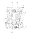
- the perspective view which shows the rotary electric machine which concerns on embodiment of this invention The figure which shows the internal structure of the rotary electric machine of FIG.
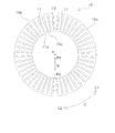
- the perspective view which shows the stator of the rotary electric machine of FIG. The top view of the stator core in the stator of FIG.
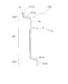
- the perspective view which shows the U-phase coil part of the stator of FIG. 5A is a perspective view showing a rectangular wire forming the U-phase coil portion of FIG. 5
- FIG. 5B is a plan view of the rectangular wire shown in FIG. 6A
- FIG. 5C is inside the slot of the rectangular wire shown in FIG.
- the perspective view which shows the U-phase coil part group of the stator of FIG. FIG. 4 is a perspective view showing a stator core and a U-phase coil unit set of the stator of FIG. 3.
- positioned one U-phase coil part group to the stator core of FIG. The schematic diagram which showed the state which has arrange
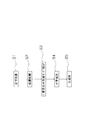
- positioning of the segment conductor of each phase in the stator shown in FIG. The flowchart which shows the process for forming the segment conductor of FIG. 7, and the segment conductor of FIG. (A), (b), (c) The figure for demonstrating formation of the segment conductor of FIG.
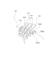
- the perspective view for demonstrating welding of the segment conductor of FIG. 7, and the segment conductor of FIG. The perspective view which shows the state after welding of the segment conductor of FIG. 7, and the segment conductor of FIG. (A)
- the figure which shows the segment conductor in the modification of embodiment concerning this invention, (b) The figure which shows the junction part using the segment conductor shown to Fig.20 (a), (c) The plane of FIG.20 (b) Figure. (A), (b) The figure which shows the junction part using the segment conductor in the modification of embodiment concerning this invention.
- FIG. 1 is a perspective view showing an external appearance of the rotating electrical machine 1 of the present embodiment
- FIG. 2 is a cross-sectional view taken along a plane passing through the central axis A to show the internal configuration of the rotating electrical machine 1 of FIG. .
- a swing machinery 100 is shown as an example of an object driven by the driving force of the rotating electrical machine 1 of the present embodiment.
- the rotating electrical machine 1 of the present embodiment is disposed on the upper side of the swing machinery 100, and the driving force generated in the rotating electrical machine 1 is transmitted to the swing machinery 100.
- the swing machinery 100 turns an upper turning body having a work implement or the like with respect to a lower traveling body having a crawler track in a work vehicle such as a hydraulic excavator.
- the rotational driving force of the rotating electrical machine 1 is transmitted to the output gear through the speed reduction mechanism, and the swing machinery 100 rotates and moves inside or outside the swing circle engaged with the output gear. Turns.
- the rotating electrical machine 1 of Embodiment 1 is a three-phase AC rotating electrical machine, and includes a housing 5 that houses a stator 2, a rotor 3, and a shaft 4 as shown in FIG.
- the housing 5 is formed so as to cover the upper surface portion 102 of the swing machinery 100, and includes a cylindrical portion 51 and a ceiling portion 52.
- the stator 2 is disposed in the housing 5 and will be described later in detail.
- the stator 2 has an annular shape having a space in the center and includes a coil 20 (see FIG. 3 described later).
- the rotor 3 is rotatably disposed in the central space of the stator 2.
- the rotor 3 has a cylindrical shape, and a magnet is provided on the outer peripheral side thereof. Note that the rotor 3 rotates about the vertical direction in the figure.
- the shaft 4 is disposed at the center of the rotor 3 and rotates together with the rotor 3.
- a bearing portion 6 a that rotatably supports the shaft 4 is provided on the ceiling portion 52 of the housing 5, and a bearing portion 6 b is provided on the upper surface portion 102 of the swing machinery 100.
- the shaft 4 is connected to the shaft 103 of the swing machinery 100 at the lower end thereof.
- FIG. 3 is a perspective view showing the stator 2 of the present embodiment.
- the stator 2 of the present embodiment has a central axis A, has a cylindrical stator core 10, and a coil 20 attached to the stator core 10, and has an upper end surface 10 a and a lower end surface 10 b.
- FIG. 4 is a plan view showing the stator core 10.
- a slot 11 is formed in the stator core 10 from the inner peripheral surface 10c toward the outer peripheral surface 10d. Forty-eight slots 11 are formed at equal intervals, and teeth 12 are formed between the slots 11. Further, the opening of the slot 11 provided in the inner peripheral surface 10c is indicated as 11a.
- the central axis of the stator core 10 is indicated by A
- the circumferential direction is indicated by C
- the radial direction is indicated by R in a plan view viewed from the axial direction.
- the central axis A is the rotation center of the rotor 3, and the axial direction indicates a direction parallel to the central axis A.
- the circumferential direction C is a direction along the outer peripheral surface 10 d of the stator core 10.
- the counterclockwise direction in a plan view when the upper end surface 10a is viewed from above in the axial direction is C1
- the clockwise direction is C2.
- both C1 and C2 are shown.
- the radial direction R is a direction connecting the outer peripheral surface 10d of the stator core 10 from the central axis A in a plan view viewed from the axial direction.
- the inner direction is indicated as R1
- the outer direction is indicated as R2.
- the vertical direction is defined in a state where the central axis A is arranged in a direction perpendicular to the ground, and the upper end surface of the stator core 10 is called the upper end surface 10a, and the lower end surface is called the lower end surface 10b.
- the arrangement direction of the stator 10 is not limited to this direction, and may be arranged so that the central axis A is horizontal with respect to the ground. Horizontal in this specification does not mean only horizontal in a strict sense. Since variations occur due to machining, bending, and assembly of the component parts, they do not necessarily fall within the accuracy defined by geometry, but in the present application, they are described as horizontal.
- the coil 20 of this embodiment has a plurality of phase coils 21. Since the rotary electric machine 1 of this embodiment is a three-phase rotary electric machine, a U-phase coil 21U, a V-phase coil 21V, and a W-phase coil 21W are provided as the phase coil 21 as shown in FIG. Each phase coil 21 has a plurality of coil portions 22 formed by joining a plurality of segment conductors 200 and 300, respectively.
- FIG. 5 is a perspective view of the U-phase coil portion 22U.
- U-phase coil 21U has a plurality of U-phase coil portions 22U.
- the U-phase coil portion 22U is formed by joining a segment conductor 200 and a segment conductor 300 formed by the flat wire 9. The flat wire 9 will be described first.
- the flat wire 9 is made of, for example, copper, and its surface is covered with an insulating film such as enamel.
- the rectangular wire 9 has a rectangular cross-sectional shape, and has a first surface 9a facing each other and a second surface 9b facing each other.
- W1 is formed larger than W2.
- the ratio of W1 and W2 is, for example, formed from 1: 2 to 1: 3.
- FIG. 6C is a diagram showing the arrangement of the flat wire 9 in the slot 11. As will be described in detail later, in this embodiment, three segment conductors 200 and three segment conductors 300 are alternately arranged in order from the outer peripheral surface 10 d side in one slot 11.
- the first surface 9a of each rectangular wire 9 is perpendicular to the circumferential direction C (which can be said to be parallel to the radial direction R), and the second surfaces 9b of the adjacent rectangular wires 9 are adjacent to each other. It arrange
- the U-phase coil portion 22 ⁇ / b> U is formed by alternately connecting four segment conductors 200 and four segment conductors 300 along the circumferential direction C.
- the lower ends of one segment conductor 200 and one segment conductor 300 form coil portion ends 22a and 22b that are ends of the U-phase coil portion 22U.
- the segment conductor 300, the segment conductor 200, the segment conductor 300, the segment conductor 200, the segment conductor 300, the segment conductor 200, and the segment conductor 300 in a counterclockwise direction when viewed from above from the segment conductor 200 having the coil portion end 22 a. It arrange
- the segment conductor 200 having the coil part end 22a which is the end of the U-phase coil part 22 is numbered in order in the circumferential direction C1 as the first segment conductor 200 (shown by hatching in FIG. 5), the first The segment conductor 200 and the second segment conductor 300 are joined at the joint 22c at the respective upper ends.
- the second segment conductor 300 and the third segment conductor 200 are joined by a joining portion 22d at the respective lower ends.
- the third segment conductor 200 and the fourth segment conductor 300 are joined at the joint 22c at the respective upper ends.
- the 4th segment conductor 300 and the 5th segment conductor 200 are joined by the joining part 22d of each lower end.
- the fifth segment conductor 200 and the sixth segment conductor 300 are joined at the joint 22c at the respective upper ends.
- the sixth segment conductor 300 and the seventh segment conductor 200 are joined at the joint 22d at the lower end thereof.
- the seventh segment conductor 200 and the eighth segment conductor 300 are joined at the joint 22c at the upper end of each.
- the lower end portion of the eighth segment conductor 300 forms a coil portion end 22 b that is an end of the coil portion 22.
- the segment conductor 200 is joined to the segment conductor 300 disposed adjacent to the circumferential direction C1 side by the joint 22c at the upper end, and the segment conductor 300 disposed adjacent to the circumferential direction C2 side. Are joined by a joint 22d at the lower end.
- the segment conductors 200 and 300 that form each phase coil 21 will be described.
- FIG. 7 is a perspective view showing the segment conductor 200. As described with reference to FIG. 6A, the segment conductor 200 is disposed in the slot 11 with the first surface 9 a perpendicular to the circumferential direction C.
- the segment conductor 200 is formed by bending the rectangular wire 9 while keeping the first surface 9a perpendicular to the circumferential direction C (the first surface 9a is parallel to the radial direction R).
- the segment conductor 200 is formed while the first surface 9a is kept parallel to the radial direction R.
- the segment conductor 200 protrudes from the upper end surface 10a and the lower end surface 10b of the stator core 10 in a state where it is disposed in the slot 11 as shown in FIG.
- the segment conductor 200 has a straight portion 201 disposed in the slot 11, a first protrusion 202 protruding from the upper end surface 10a, and a second protrusion 203 protruding from the lower end surface 10b.
- the first projecting portion 202 is bent in the circumferential direction C1 with respect to the straight portion 201, and the second projecting portion 203 is bent in the circumferential direction C2.
- the first projecting portion 202 of the segment conductor 200 includes an inclined portion 202a formed in the circumferential direction C1 from the upper end of the linear portion 201 (the portion protruding from the slot 11), and the upper end surface 10a from the tip of the inclined portion 202a. And a vertical portion 202b formed in the vertical direction.
- the bent portion between the straight portion 201 and the inclined portion 202a and between the inclined portion 202a and the vertical portion 202b is bent on the first surface 9a side of the flat wire 9 and the second surface 9b is held on the same plane.
- Vertical in this specification does not mean only vertical in a strict sense. Since variations occur due to machining, bending, and assembly of the component parts, the accuracy does not necessarily fall within the accuracy defined by the geometry, but in this application, it is described as vertical.
- the second projecting portion 203 of the segment conductor 200 includes an inclined portion 203a formed by being bent from the lower end of the linear portion 201 (the portion protruding from the slot 11) toward the lower end surface 10b in the circumferential direction C2, and the inclined portion 203a. And a vertical portion 203b formed in a vertical direction with respect to the lower end surface 10b.
- the first surface 9a side of the flat wire 9 is bent, and the second surface 9b is held on the same plane. .
- FIG. 8 is a perspective view showing the segment conductor 300.
- the segment conductor 300 has the first surface 9 a disposed in the slot 11 in a state perpendicular to the circumferential direction C.
- the segment conductor 300 is formed by bending the rectangular wire 9 while keeping the first surface 9a perpendicular to the circumferential direction C (the first surface 9a is parallel to the radial direction R).
- the segment conductor 300 is formed in a state in which the first surface 9a is kept parallel to the radial direction R.
- the segment conductor 300 protrudes from the upper end surface 10a and the lower end surface 10b of the stator core 10 in a state where it is disposed in the slot 11 as shown in FIG.
- the segment conductor 300 has a straight portion 301 disposed in the slot 11, a first protruding portion 302 protruding from the upper end surface 10a, and a second protruding portion 303 protruding from the lower end surface 10b. is doing.
- the first protrusion 302 is bent in the circumferential direction C2
- the second protrusion 303 is bent in the circumferential direction C1.
- the first projecting portion 302 of the segment conductor 300 includes an inclined portion 302a formed in the circumferential direction C2 from the upper end of the straight portion 301 (the portion protruding from the slot 11), and the upper end surface 10a from the tip of the inclined portion 302a.
- the bent portion between the straight portion 301 and the inclined portion 302a and the bent portion between the inclined portion 302a and the vertical portion 302b are bent on the first surface 9a side of the flat wire 9, and the second surface 9b is on the same plane. Is retained.
- the bent portion between the vertical portion 302b and the horizontal portion 302c is bent on the second surface 9b side of the rectangular wire as shown in the enlarged view of the T portion in FIG. 8, and the first surface 9a is held on the same plane.
- the rectangular wire 9 is bent by about 90 degrees from the vertical portion 302b to the horizontal portion 302c.
- the direction in which the flat wire 9 is bent is a direction toward the radially outer side R2 when the segment conductor 300 is attached to the stator core 10.
- the second projecting portion 303 of the segment conductor 300 includes an inclined portion 303a formed in the circumferential direction C1 from the lower end of the straight portion 301 (the portion protruding from the slot 11), and the lower end surface 10b from the tip of the inclined portion 303a.
- the bent portion between the straight portion 301 and the inclined portion 303a and the bent portion between the inclined portion 303a and the vertical portion 303b are bent on the first surface 9a side of the flat wire 9, and the second surface 9b is on the same plane. Is retained.
- the second surface 9b side of the flat wire is bent, and the first surface 9a is held on the same plane.
- the flat wire 9 is bent about 90 degrees from the vertical portion 303b to the horizontal portion 303c.
- the direction in which the flat wire 9 is bent is a direction toward the radially outer side R ⁇ b> 2 when the segment conductor 300 is mounted on the stator core 10.
- the vertical portion 202b of the segment conductor 200 and the horizontal portion 302c of the segment conductor 300 are joined at the joint portion 22c by TIG welding or the like, and the vertical portion 203b and the segment conductor of the segment conductor 200 are joined.
- 300 horizontal portions 303c are joined at the joining portion 22d to form each phase coil 21.
- the horizontal portion 303c is not formed, only the vertical portion 303b is formed, and the vertical portion 303b connects the coil end 22b. It is composed.
- FIG. 9 is a perspective view of the U-phase coil unit set 23U.
- FIG. 10 is a perspective view showing a state in which only the U-phase coil unit set 23 ⁇ / b> U is arranged on the stator core 10.
- the segment conductors 200 and 300 of one U-phase coil portion 22U are arranged with the segment conductors 200 and 300 adjacent in the circumferential direction C and five slots 11 therebetween.
- the segment conductors 200 and 300 are arranged in the same slot 11.
- the first segment conductor 200 having the coil portion ends 22a of the three U-phase coil portions 22U is disposed in the same slot 11, and each second segment conductor 300 is disposed in one slot 11. Placed inside.
- the third to eighth segment conductors 200 and 300 are arranged in one slot 11.
- the joining portions 22c of the three U-phase coil portions 22U in the U-phase coil portion set 23U are arranged side by side along the radial direction R on the upper end surface 10a side, and the joining portions 22d are arranged on the lower end surface 10b side.
- four such U-phase coil unit sets 23U are arranged to form a U-phase coil 21U.
- FIG. 11 is a schematic view of a state in which one U-phase coil portion set 23U is mounted on the stator core 10 as viewed from the inner peripheral surface 10c side. Actually, three flat wires 9 are arranged in the depth direction of the drawing, but only one flat wire 9 is shown for easy understanding.
- the U-phase coil 21U is configured by combining four U-phase coil unit sets 23U. In order to distinguish each of the four U-phase coil unit sets 23U, a first U-phase coil unit set 23 (1) U, a second U-phase coil unit set 23 (2) U, and a third U-phase coil unit The set 23 (3) U and the fourth U-phase coil unit set 23 (4) U are shown.
- the segment conductors 200 and 300 when describing the segment conductors 200 and 300 of the first U-phase coil unit set 23U, they are referred to as 200 (1) and 300 (1), and the other U-phase coil unit sets 23 (2).
- 23 (3) and 23 (4) are described as 200 (2), 300 (2), 200 (3), 300 (3), 200 (4), and 300 (4).
- FIG. 11 schematically shows a state in which only the first U-phase coil unit set 23 (1) U is attached to the stator core 10.
- FIG. 12 is a diagram illustrating a state in which the first U-phase coil unit set 23 (1) U and the second U-phase coil unit set 23 (2) U are attached to the stator core 10.
- the second U-phase coil unit set 23 (2) U is indicated by a dotted line to distinguish it from the first U-phase coil unit set 23 (1) U.
- the second U-phase coil unit set 23 (2) U is moved from the first U-phase coil unit set 23 (1) U by six slots 11 in the circumferential direction C. 10 is attached.
- the segment conductor 200 of the first U-phase coil unit set 23 (1) U and the segment conductor 300 of the second U-phase coil unit set 23 (2) are arranged in the same slot 11.
- the segment conductor 300 of the first U-phase coil unit set 23 (1) U and the segment conductor 200 of the second U-phase coil unit set 23 (2) U are arranged in the same slot 11.
- the joint portion 22d (2) of the second U-phase coil portion set 23 (2) U is located below the stator core 10 of the joint portion 22c (1) of the first U-phase coil portion set 23 (1) U. Has been placed.
- the joint portion 22d (1) of the first U-phase coil portion set 23 (1) U is located below the stator core 10 of the joint portion 22c (2) of the second U-phase coil portion set 23 (2) U. Has been placed.
- FIG. 12 only one segment conductor 200, 300 is shown for each of the first U-phase coil unit set 23 (1) U and the second U-phase coil unit set 23 (2) U in one slot 11. Although not actually, three are arranged in one slot 11.
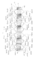
- FIG. 13 is a diagram for explaining the arrangement of the segment conductors 200 and 300 in the slot 11 of the first U-phase coil unit set 23 (1) and the second U-phase coil unit set 23 (2).
- the segment conductor 200 (1) of the first U-phase coil section set 23 (1) and the segment conductor 300 (2) of the second U-phase coil section set 23 (2) 11 are alternately arranged.
- segment conductor 300 (2), the segment conductor 200 (1), the segment conductor 300 (2), the segment conductor 200 (1), and the segment conductor 300 (2) in the direction from the inner peripheral surface 10c to the outer peripheral surface 10d.
- segment conductor 200 (1) in this order.
- the segment conductor 300 (1), the segment conductor 200 (2), the segment conductor 300 (1), the segment conductor 200 (2), the segment conductor 300 (1), and the segment conductor 200 (2) Arranged in order.
- a total of six segment conductors 200, 300 are included in the order of the segment conductor 300 and the segment conductor 200 from the inner peripheral surface 10c to the outer peripheral surface 10d.
- the joint portion between the segment conductor 200 and the segment conductor 300 will be described in more detail.
- the first surface 9a of the horizontal portion 302c of the segment conductor 300 (indicated by P1 in parentheses in the drawing) and the vertical portion of the segment conductor 200
- the first surface 9a of 202b (indicated by P2 in parentheses in the drawing) is abutted and joined so as to face each other.
- the rectangular wire 9 has two first surfaces 9a.
- the segment to be joined to the first surface 9a of the vertical portion 202b on the slot 11 side where the segment conductor 300 to be joined is disposed.
- the first surface 9a of the horizontal portion 302c on the slot 11 side where the conductor 200 is disposed faces each other.
- the segment conductor 300 (1) is more inward in the radial direction R at a position in the slot 11 than the segment conductor 200 (1) joined thereto. Is arranged. Since the horizontal portion 302c of the segment conductor 300 (1) extends outward, the first surface 9a of the horizontal portion 302c of the segment conductor 300 (1) and the segment as shown in the enlarged view of the X portion of FIG. The first surfaces 9a of the vertical portions 202b of the conductor 200 (1) can face each other and come into contact with each other.
- FIG. 13 shows the second segment conductor 200 (1) and the first segment conductor 300 (1) from the inner side toward the outer peripheral surface 10d from the inner peripheral surface 10c of the stator core 10 are at the upper end side. It is joined.
- the fourth segment conductor 200 (1) from the inside and the third segment conductor 300 (1) from the inside are joined at the upper end side.
- the sixth segment conductor 200 (1) from the inside and the fifth segment conductor 300 (1) from the inside are joined at the upper end side.
- FIG. 13 shows the segment conductor 200 (1) of the outermost U-phase coil portion 22U as T and the segment conductor 300 (2) as Q.
- segment conductor 200 and the segment conductor 300 are combined, the segment conductor 200 arranged i + 1 (i is 1 or more) from the inside, and the segment conductor 300 arranged i-th from the inside are joined. Yes. Since the segment conductor 200 and the segment conductor 300 are arranged in this order from the inner side of the starter core 10 toward the radially outer side R2, i is an odd number.
- the first surfaces of the respective vertical portions 303b and horizontal portions 303c. 9a is opposed and joined.
- the first U-phase coil unit set 23 (1) U and the second U-phase coil unit set 23 (2) are combined.
- this combination is used. There are two sets.
- FIG. 14 is a schematic diagram showing a state where four sets of U-phase coil sections 23U are mounted on the stator core 10.
- the third U-phase coil unit set 23 (3) is shifted from the first U-phase coil unit set 23 (1) U by one slot 11 in the circumferential direction C 1 to the stator core 10. Is arranged.
- the fourth U-phase coil portion set 23 (4) is arranged on the stator core 10 with one slot 11 shifted in the circumferential direction C1 from the second U-phase coil portion set 23 (2).
- the segment conductors 200 (3) of the third U-phase coil unit set 23 (3) and the segment conductors 300 (4) of the fourth U-phase coil unit set 23 (4) are alternately arranged in the same slot 11. ing. Further, the segment conductor 300 (3) of the third U-phase coil section set 23 (3) and the segment conductor 200 (4) of the fourth U-phase coil section set 23 (4) are alternately placed in the same slot 11. Is arranged. As described above, the segment conductors 300 (3) and the segment conductors 200 (4) are alternately arranged in the order from the inner peripheral surface 10c to the outer peripheral surface 10d. The segment conductors 300 (4) and the segment conductors 200 (3 ) Are arranged alternately in this order.
- U-phase coil unit sets 23U are combined to form U-phase coil 21U.
- the U-phase coil 21U having such a configuration and the V-phase coil 21V and the W-phase coil 21W having the same configuration as the U-phase coil 21U are mounted on the stator core 10.
- FIG. 15 is a partial plan view for explaining a mounting state of each phase coil 21 to the stator core 10.
- the segment conductors 200 and 300 of the first U-phase coil unit set 23 (1) U are illustrated as 200 (1) U and 300 (1) U as an example.
- the second, third, and fourth U-phase coil sections 23 (2) U, 23 (3) U, and 23 (4) U are also 200 (2) U, 300 (2) U, 200 ( 3) Shown as U, 300 (3) U, 200 (4) U, 300 (4) U.
- First to fourth V-phase coil sections 21 (1) V to 21 (4) V segment conductors 200 and 300 of the V-phase coil 21V, and first to fourth W-phase coil sections of the W-phase coil 21W The same applies to the segment conductors 200 and 300 of 21 (1) W to 21 (4) W.
- a symbol in which dots are arranged in the circles in the segment conductors 200 and 300 indicates that a current flows from the back to the front of the paper, and a symbol in which x is arranged in the circles It shows that current flows from the front to the back.
- the first slot 11A includes the segment conductor 200 (1) U of the first U-phase coil unit set 23 (1) U, the second The segment conductors 300 (2) U of the U-phase coil unit set 23 (2) U are alternately arranged.
- the slot 11A is the first, and the second slot 11 in the circumferential direction C1 includes the segment conductor 200 (3) U of the third U-phase coil unit set 23 (3) U and the fourth U-phase coil unit set 23. (4) U segment conductors 300 (4) U are alternately arranged.
- the third slot 11 includes a segment conductor 200 (1) V of the first V-phase coil section set 23 (1) V and a segment conductor 300 (2) of the second U-phase coil section set 23 (2) V. ) V are alternately arranged.
- the segment conductor 200 (3) V of the third V-phase coil section set 23 (3) V and the segment conductor 300 of the fourth V-phase coil section set 23 (4) V are provided. (4) V is alternately arranged.
- the fifth slot 11 includes a segment conductor 200 (1) W of the first W-phase coil section set 23 (1) W and a segment conductor 300 (2) of the second W-phase coil section set 23 (2) W. ) W are alternately arranged.
- the next sixth slot 11 includes a segment conductor 200 (3) W of the third W-phase coil section set 23 (3) W and a segment conductor 300 of the fourth W-phase coil section set 23 (4) W. (4) Ws are arranged alternately.
- the seventh slot 11 includes a segment conductor 200 (2) U of the second U-phase coil unit set 23 (2) U and a segment conductor 300 (1) of the first U-phase coil unit set 23 (1) U. ) U are alternately arranged.
- the next eighth slot 11 includes a segment conductor 200 (4) U of the fourth U-phase coil section set 23 (4) U and a segment conductor 300 of the third U-phase coil section set 23 (3) U. (3) U are alternately arranged.
- the ninth slot 11 includes a segment conductor 200 (2) V of the second V-phase coil section set 23 (2) V and a segment conductor 300 (1) of the first V-phase coil section set 23 (1) V. ) V are alternately arranged.
- the next tenth slot 11 includes a segment conductor 200 (4) V of the fourth V-phase coil section set 23 (4) V and a segment conductor 300 of the third V-phase coil section set 23 (3) V. (3) V is alternately arranged.
- the eleventh slot 11 includes a segment conductor 200 (2) W of the second W-phase coil section set 23 (2) W and a segment conductor 300 (1) of the first W-phase coil section set 23 (1) W. ) W are alternately arranged.
- the twelfth slot 11 includes a segment conductor 200 (4) W of the fourth W-phase coil section set 23 (4) W and a segment conductor 300 (3) of the third W-phase coil section set 23 (3) W. ) W are alternately arranged.
- the segment conductors 200 and 300 of the respective phase coils 21 are arranged in the same manner as in the first to twelfth slots 11.
- the thirteenth slot 11 includes the segment conductor 200 (1) U of the first U-phase coil unit set 23 (1) U and the second U-phase coil unit set 23.
- the U segment conductors 300 (2) U are alternately arranged.
- the arrangement in the first to twelfth slots 11 is repeated four times in the circumferential direction C1, and the U-phase coil 21U, the V-phase coil 21V, and the W-phase are provided in the 48 slots 11.
- the stator 21 of this embodiment is configured by mounting the coil 21W. As shown in FIG. 15, in the first and second slots 11, current flows from the back to the front, and in the third and fourth slots 11, current flows from the front to the back. In this way, the direction of the current is switched every two slots 11 in the circumferential direction C.
- the coil part ends 22a and 22b shown in FIG. 5 are appropriately connected by the connection line 90 and the like shown in FIG.
- the manufacture of the stator according to the present embodiment includes a segment conductor creating process for forming the segment conductors 200 and 300, an arrangement process for arranging the segment conductors 200 and 300 on the stator core 10, and a welding process for welding between the segment conductors 200 and 300. And.
- FIG. 16 is a flowchart showing a method of creating the segment conductors 200 and 300 of the present embodiment.
- FIGS. 17A to 17C are diagrams for explaining the process of creating the segment conductor 300.
- the coating films at both ends of the segment conductors 200 and 300 are peeled off (S2). This film peeling is performed by scraping off the film by punching using a mold. Subsequently, for the segment conductors 300 arranged i-th from the inside of the stator core 10, specifically, odd-numbered segments counted from the inside of the stator core 10, the tips of both ends thereof are bent 90 degrees in the same direction ( S3). In S3, the flat wire 9 is bent in a state where the first surface 9a is kept in the same plane, and horizontal portions 302c and 303c are formed as shown in FIG. 17A (see the J portion surrounded by the dotted line). ).
- the segment conductor 200 and the segment conductor 300 are formed in an S shape (S4).
- S4 as shown in FIG. 17B, the first surface 9a is bent so that the second surface 9b of the flat wire 9 is held on the same plane (see the K portion surrounded by a dotted line).
- the segment conductors 200 and 300 are formed in an R shape so as to be curved along the circumferential direction C of the stator core 10 (S5).
- S5 as shown in FIG. 17 (c)
- the segment conductor 300 inclined portion 302a and the inclined portion 303a are formed to be curved along the circumferential direction C of the stator core 10 (see the L portion surrounded by a dotted line). ).
- the segment conductor 200 is formed in the same manner as the segment conductor 300 except that the step S3 is not performed. As a result, the segment conductors 200 and 300 are created.
- segment conductors 200 and 300 are disposed in the slots 11 of the stator core 10.
- the segment conductors 200 and 300 are arranged in the slot 11 from the inner peripheral surface 10c of the stator core 10 through the opening 11a of the slot 11 (see FIG. 4). Is done.
- FIG. 18 is a diagram illustrating a state in which the joint is welded.
- a plurality of scheduled welding portions 800 that are opposed to a vertical portion 202b and a horizontal portion 302c that are to be welded.
- a wedge-shaped welding electrode 701 is inserted between the plurality of planned welding portions 800 from the outer peripheral surface 10d side of the stator core 10 between the vertical portion 202b and the horizontal portion 302c to be welded.
- a power cord 702 is connected to the welding electrode 701, and a welding torch 703 is disposed above the planned welding portion 800.
- a conductive wedge 704 is inserted into the gap between the planned welding portions 800.
- two wedges 704 are inserted.
- the opposed portions of the vertical portion 202b and the horizontal portion 302c are TIG welded from above.
- the wedge 704 between the welding electrode 701 and the planned welding portion 800 By inserting the wedge 704 between the welding electrode 701 and the planned welding portion 800, a stable planned welding portion is ensured.
- a joint portion 22 c is formed at a portion where the vertical portion 202 b and the horizontal portion 302 c face each other.
- FIG. 19 also shows a portion that is not joined (scheduled joining portion 800).
- the joining portion 22d is also formed in the portion where the vertical portion 203b on the lower end surface 10b side and the horizontal portion 303c face each other.
- a connection line 90 (see FIG. 3) is appropriately provided to manufacture the stator 2 of the present embodiment. ⁇ 3.
- the stator 2 of the above embodiment includes a stator core 10 and a coil 20.
- the stator core 10 is cylindrical and has a plurality of slots 11 formed along the radial direction on the inside thereof.
- the coil 20 includes a plurality of segment conductors 200 and 300 arranged in the slot 11, and the vertical portions 202 b and 203 b (an example of the end portion) of the segment conductor 200 and the horizontal portions 302 c and 303 c (an example of the end portion) of the segment conductor 300. ) Are joined together.
- the segment conductors 200 and 300 have a rectangular cross section, and are formed by a flat wire 9 having a first surface 9a having a large width and a second surface 9b having a small width.
- the first surface 9 a is disposed in the slot 11 so as to be parallel to the radial direction R.
- a plurality of segment conductors 200 and 300 are arranged so that the second surfaces 9b face each other.
- the first surfaces 9a are opposed to each other.
- the joined first surfaces 9 a are formed in parallel with the radial direction R.
- the segment conductors 200 and 300 are joined at the wide first surfaces 9a, even if welding is performed without compressing the ends of the segment conductors 200 and 300, sufficient joint strength is obtained. Can be secured. Since it is not necessary to compress the end portions of the segment conductors 200 and 300, it is possible to provide the stator 2 that can ensure a sufficient bonding strength even if the portions to be joined are dense. Although it is necessary to ensure the same cross-sectional area as the segment conductors 200 and 300 in the joining part, since the wide 1st surface 9a is made to oppose and is joined, the joining depth is set to the width
- the horizontal portions 302c and 303c (an example of the end portion) of the i-th segment conductor 300 are i + 1-th segment conductor 200 so that the second surface 9b is curved. Are bent outward toward the vertical portions 202b and 203b (an example of an end portion) and joined to the vertical portions 202b and 203b of the (i + 1) th segment conductor 200.
- the positions of the vertical portions 202 b and 203 b and the horizontal portions 302 c and 303 c of the segment conductors 200 and 300 to be joined are located closer to the outside of the stator core 10.
- the vertical portions 202b and 203b of the two segment conductors 200 to be joined and the horizontal portions 302c and 303c of the segment conductor 300 are kept in contact with each other. Therefore, the wedge-shaped welding electrode 701 and the wedge 704 are inserted from the outer peripheral side of the stator core 10 to the outer side in the circumferential direction C of the end portions of the vertical portions 202b and 203b and the horizontal portions 302c and 303c arranged to face each other.
- the position where the two vertical parts 202b and 203b to be joined and the horizontal parts 302c and 303c are located closer to the outside of the stator core 10 is the position to be joined adjacent to the circumferential direction C (the part to be joined 800). Since the interval is wide, the welding electrode 701 can be easily inserted. Since it is not necessary to make the tip of the welding electrode 701 extremely thin, the manufacturing of the welding electrode 701 is facilitated.
- the first surfaces 9a facing each other are, as shown in FIG. 13, the first surface 9a on the slot 11 side where the i + 1th segment conductor 200 of the ith segment conductor 300 is disposed. (Referred to as P1 in parentheses in FIG. 13) and the first surface on the slot side where the i-th segment conductor 300 of the (i + 1) th segment conductor 200 is disposed (indicated as P2 in parentheses in FIG. 13). It is. Thereby, it becomes possible to join the segment conductors 200 and 300 at a short distance.
- the segment conductors 200 and 300 include the straight portions 201 and 301 (an example of a portion in the slot) disposed in the slot 11 and the upper end surface 10a (first end surface) of both end surfaces of the stator core 10.
- First protrusions 202 and 302 protruding from one example
- second protrusions 203 and 303 protruding from the lower end surface 10b (an example of the second end surface) of both end surfaces.
- the vertical portions 202b and 203b and the horizontal portions 302c and 303c are provided on both the first projecting portions 202 and 302 and the second projecting portions 203 and 303, and are joined to the opposed first surfaces.
- 9a is provided in both the 1st protrusion parts 202 and 302 side and the 2nd protrusion parts 203 and 303 side.
- the segment conductors 200 and 300 are respectively formed with vertical portions 202b and 203b and horizontal portions 302c and 303c at portions protruding from both end faces of the stator core 10, and the vertical portions 202b and 203b and horizontal portions 302c and 303c.
- the other segment conductors 200 and 300 are joined together.
- Each segment conductor 200, 300 is not formed so as to cross two or more slots 11, and is disposed only in one slot 11. Thereby, even after bending, the segment conductors 200 and 300 can be inserted into the slot 11 from the inside of the stator core 10. Since it is not necessary to perform bending after the segment conductors 200 and 300 are inserted into the slots 11, the processing can be easily performed.
- the rotating electrical machine 1 includes a stator 2 and a rotor 3 disposed inside the stator 2. Thereby, the rotary electric machine 1 provided with the stator 2 which can ensure sufficient joint strength is realizable.
- FIG. 20A is a diagram showing a configuration in which a step 901 is formed on the first surface 9a of the horizontal portion 302c of the segment conductor 300.
- a step is formed on the first surface 9 a of the horizontal portion 302 c of the segment conductor 300, and a step surface 901 a is formed perpendicular to the upper end surface 10 a when mounted on the stator core 10.
- the step surface 901a is provided over the entire width W1 of the first surface 9a (see FIG. 6).
- the width of the second surface 9b of the flat wire 9 from the tip of the horizontal portion 302c to the portion where the step surface 901a is formed is constant, but the length of the width is from W2 (see FIG. 6). Is also small.
- FIG. 20B is a diagram showing a state in which the vertical portion 202b of the segment conductor 200 and the horizontal portion 302c of FIG. 20A are combined.
- the segment conductor 200 and the segment conductor 300 are combined so that the second surface 9b inside the vertical portion 202b of the segment conductor 200 abuts on the step surface 901a.
- a step 901 is formed on the first surface 9a so that the width of the second surface 9b is narrowed.
- the step surface 901a formed perpendicular to the first surface 9a by the step 901 is disposed perpendicular to the radial direction, and the step surface 901a includes the second surface inside the i + 1th segment conductor 200. 9b contacts.
- Fig. 20 (c) is a plan view of Fig. 20 (b) and is a diagram for explaining a welding state.
- FIG. 20C when the wedge-shaped welding electrode 701 is inserted from the outer peripheral surface 10d side, the vertical portion 202b and the horizontal portion 302c are pushed toward the radially inner side R1.
- the step 901 serves as a stopper when the (i + 1) th segment conductor 200 moves inward.
- the horizontal portions 302c and 303c (an example of the end portion) of the i-th segment conductor 300 have the vertical portions 202b and 203b (end portions) of the i + 1-th segment conductor 200 such that the second surface 9b is curved. Is bent outward toward one example) and joined to the vertical portions 202b and 203b of the i + 1th segment conductor 200, but a horizontal portion is formed inward on the i + 1th segment conductor 200, It may be joined to the vertical part of the i-th segment conductor 300 in which the horizontal part is not formed.
- the segment conductor 300 located inside the radial direction R extends toward the outer side (radial outside R2), and the segment conductor 200 located outside the radial direction R faces inward. It extends toward the end and may be joined to the segment conductor 300 on the inner side in the radial direction R.
- a horizontal portion 202c is formed from the tip of the vertical portion 202b of the segment conductor 200 ′ toward the radially inner side R1.
- the horizontal portion 302c is not formed from the tip of the vertical portion 302b.
- the horizontal part 202c and the mutual 1st surface 9a of the vertical part 302b are joined facing each other.
- the segment conductor 200 ′ formed with the horizontal portion 202c and the segment conductor 300 formed with the horizontal portion 302c may be joined.
- the first surfaces 9a of the horizontal portion 202c and the horizontal portion 302c are joined to face each other.
- D In the above embodiment, as shown in FIG. 13, the first surface 9a on the slot 11 side where the i + 1th segment conductor 200 of the i-th segment conductor 300 is disposed (indicated by P1 in parentheses in FIG. 13), although the first surface 9a (P2) on the slot 11 side where the i-th segment conductor 300 of the (i + 1) -th segment conductor 200 is disposed is opposed and joined, it is not limited thereto.
- the first surface 9a of the i-th segment conductor 300 opposite to the slot 11 in which the i + 1-th segment conductor 200 is disposed (indicated by P3 in parentheses in FIG. 22)
- the first surface 9a of the (i + 1) th segment conductor 200 opposite to the slot 11 in which the i-th segment conductor 300 is disposed (indicated by P4 in parentheses in FIG. 22) is opposed and joined. Good.
- the rotating electrical machine 1 including the stator 2 is used for driving the swing machinery 100, but is not limited to the swing machinery 100.
- the rotary electric machine 1 may be arrange
- stator of the present invention and the rotating electrical machine including the stator can ensure a sufficient joint strength even when the parts to be joined are densely packed. It is useful as a drive motor of
Landscapes
- Engineering & Computer Science (AREA)
- Power Engineering (AREA)
- Windings For Motors And Generators (AREA)
Abstract
Selon l'invention, des segments conducteurs (200, 300) qui forment une bobine (20) dans ce stator (2) se composent de fils rectangulaires (9) et sont placés chacun dans une fente (11) de telle sorte qu'une première surface large (9a) de ce segment conducteur (200, 300) soit parallèle à une direction radiale (R). De multiples segments conducteurs (200, 300) sont placés dans chaque fente (11) de telle sorte que des secondes surfaces étroites (9b) desdits segments conducteurs (200, 300) soient orientées les unes vers les autres. Le i-ième (i étant un nombre entier supérieur ou égal à 1) segment conducteur (300) à partir de l'intérieur d'un noyau de stator (10) est relié au (i + 1)ème segment conducteur (200) dans une autre fente (11) de telle sorte que des sections verticales (202b, 203b) et des sections horizontales (302c, 303c) des premières surfaces (9a) desdits segments conducteurs (200, 300) soient orientées les unes vers les autres. Les premières surfaces unies en regard (9a) sont formées de sorte à être parallèles à la direction radiale susmentionnée (R).
Priority Applications (7)
| Application Number | Priority Date | Filing Date | Title |
|---|---|---|---|
| PCT/JP2014/059022 WO2015145696A1 (fr) | 2014-03-27 | 2014-03-27 | Stator et machine dynamo-électrique contenant celui-ci |
| PCT/JP2015/059252 WO2015147105A1 (fr) | 2014-03-27 | 2015-03-25 | Stator et machine dynamo-électrique le contenant |
| KR1020167014762A KR20160079101A (ko) | 2014-03-27 | 2015-03-25 | 스테이터 및 스테이터를 구비한 회전 전기 |
| DE112015000332.0T DE112015000332T5 (de) | 2014-03-27 | 2015-03-25 | Stator und dynamoelektrische Maschine ausgestattet mit demselben |
| US15/109,495 US20160336826A1 (en) | 2014-03-27 | 2015-03-25 | Stator and dynamo-electric machine equipped with same |
| CN201580003091.7A CN105814775A (zh) | 2014-03-27 | 2015-03-25 | 定子以及具有该定子的旋转电机 |
| JP2016510448A JP6242479B2 (ja) | 2014-03-27 | 2015-03-25 | ステータ及びそれを備えた回転電機 |
Applications Claiming Priority (1)
| Application Number | Priority Date | Filing Date | Title |
|---|---|---|---|
| PCT/JP2014/059022 WO2015145696A1 (fr) | 2014-03-27 | 2014-03-27 | Stator et machine dynamo-électrique contenant celui-ci |
Publications (1)
| Publication Number | Publication Date |
|---|---|
| WO2015145696A1 true WO2015145696A1 (fr) | 2015-10-01 |
Family
ID=54194285
Family Applications (2)
| Application Number | Title | Priority Date | Filing Date |
|---|---|---|---|
| PCT/JP2014/059022 Ceased WO2015145696A1 (fr) | 2014-03-27 | 2014-03-27 | Stator et machine dynamo-électrique contenant celui-ci |
| PCT/JP2015/059252 Ceased WO2015147105A1 (fr) | 2014-03-27 | 2015-03-25 | Stator et machine dynamo-électrique le contenant |
Family Applications After (1)
| Application Number | Title | Priority Date | Filing Date |
|---|---|---|---|
| PCT/JP2015/059252 Ceased WO2015147105A1 (fr) | 2014-03-27 | 2015-03-25 | Stator et machine dynamo-électrique le contenant |
Country Status (6)
| Country | Link |
|---|---|
| US (1) | US20160336826A1 (fr) |
| JP (1) | JP6242479B2 (fr) |
| KR (1) | KR20160079101A (fr) |
| CN (1) | CN105814775A (fr) |
| DE (1) | DE112015000332T5 (fr) |
| WO (2) | WO2015145696A1 (fr) |
Cited By (1)
| Publication number | Priority date | Publication date | Assignee | Title |
|---|---|---|---|---|
| WO2019082827A1 (fr) * | 2017-10-26 | 2019-05-02 | 三菱電機株式会社 | Stator, ensemble stator et procédé de fabrication de stator |
Families Citing this family (10)
| Publication number | Priority date | Publication date | Assignee | Title |
|---|---|---|---|---|
| WO2018135087A1 (fr) * | 2017-01-18 | 2018-07-26 | パナソニックIpマネジメント株式会社 | Structure de connexion pour bobine et barre omnibus, et moteur ayant cette structure |
| GB2559362A (en) * | 2017-02-02 | 2018-08-08 | Safran Electrical & Power | Stator winding for an electrical machine |
| JP6590872B2 (ja) * | 2017-07-10 | 2019-10-16 | 本田技研工業株式会社 | 回転電機のステータの製造方法 |
| CN109586456B (zh) * | 2017-09-29 | 2021-06-18 | 比亚迪股份有限公司 | 电机、定子组件及其线圈绕线方法 |
| JP6508318B1 (ja) * | 2017-12-25 | 2019-05-08 | 株式会社明電舎 | 回転機の固定子 |
| JP2019118159A (ja) * | 2017-12-26 | 2019-07-18 | トヨタ自動車株式会社 | セグメント導体の接合方法 |
| KR102253171B1 (ko) * | 2018-06-14 | 2021-05-18 | 현대모비스 주식회사 | 고정자 |
| JP7620401B2 (ja) * | 2020-09-04 | 2025-01-23 | 株式会社Subaru | ステータ |
| JP2024043700A (ja) * | 2022-09-20 | 2024-04-02 | 本田技研工業株式会社 | 回転電機及び回転電機の製造方法 |
| CN119324585B (zh) * | 2024-09-19 | 2025-11-21 | 华为数字能源技术有限公司 | 扁线电机、动力总成及电动车辆 |
Citations (4)
| Publication number | Priority date | Publication date | Assignee | Title |
|---|---|---|---|---|
| JP2004350381A (ja) * | 2003-05-21 | 2004-12-09 | Mitsubishi Electric Corp | 回転電機の固定子 |
| JP2010141967A (ja) * | 2008-12-09 | 2010-06-24 | Toyota Motor Corp | 回転電機 |
| JP2011229367A (ja) * | 2010-03-31 | 2011-11-10 | Denso Corp | 回転電機の固定子 |
| JP2013005516A (ja) * | 2011-06-14 | 2013-01-07 | Toyota Motor Corp | ステータおよび回転電機 |
Family Cites Families (4)
| Publication number | Priority date | Publication date | Assignee | Title |
|---|---|---|---|---|
| JP2002018589A (ja) * | 2000-07-03 | 2002-01-22 | Senju Metal Ind Co Ltd | 鉛フリーはんだ合金 |
| JPWO2011102150A1 (ja) * | 2010-02-18 | 2013-06-17 | アイシン・エィ・ダブリュ株式会社 | 回転電機用電機子 |
| JP5516989B2 (ja) * | 2010-11-04 | 2014-06-11 | アイシン・エィ・ダブリュ株式会社 | 回転電機用電機子 |
| JP5789538B2 (ja) | 2012-02-14 | 2015-10-07 | 日立オートモティブシステムズ株式会社 | 回転電機および回転電機の製造方法 |
-
2014
- 2014-03-27 WO PCT/JP2014/059022 patent/WO2015145696A1/fr not_active Ceased
-
2015
- 2015-03-25 US US15/109,495 patent/US20160336826A1/en not_active Abandoned
- 2015-03-25 WO PCT/JP2015/059252 patent/WO2015147105A1/fr not_active Ceased
- 2015-03-25 KR KR1020167014762A patent/KR20160079101A/ko not_active Ceased
- 2015-03-25 DE DE112015000332.0T patent/DE112015000332T5/de not_active Withdrawn
- 2015-03-25 CN CN201580003091.7A patent/CN105814775A/zh active Pending
- 2015-03-25 JP JP2016510448A patent/JP6242479B2/ja not_active Expired - Fee Related
Patent Citations (4)
| Publication number | Priority date | Publication date | Assignee | Title |
|---|---|---|---|---|
| JP2004350381A (ja) * | 2003-05-21 | 2004-12-09 | Mitsubishi Electric Corp | 回転電機の固定子 |
| JP2010141967A (ja) * | 2008-12-09 | 2010-06-24 | Toyota Motor Corp | 回転電機 |
| JP2011229367A (ja) * | 2010-03-31 | 2011-11-10 | Denso Corp | 回転電機の固定子 |
| JP2013005516A (ja) * | 2011-06-14 | 2013-01-07 | Toyota Motor Corp | ステータおよび回転電機 |
Cited By (2)
| Publication number | Priority date | Publication date | Assignee | Title |
|---|---|---|---|---|
| WO2019082827A1 (fr) * | 2017-10-26 | 2019-05-02 | 三菱電機株式会社 | Stator, ensemble stator et procédé de fabrication de stator |
| JPWO2019082827A1 (ja) * | 2017-10-26 | 2020-04-02 | 三菱電機株式会社 | 固定子、固定子アッセンブリおよび固定子の製造方法 |
Also Published As
| Publication number | Publication date |
|---|---|
| DE112015000332T5 (de) | 2016-09-22 |
| KR20160079101A (ko) | 2016-07-05 |
| WO2015147105A1 (fr) | 2015-10-01 |
| CN105814775A (zh) | 2016-07-27 |
| JP6242479B2 (ja) | 2017-12-06 |
| JPWO2015147105A1 (ja) | 2017-04-13 |
| US20160336826A1 (en) | 2016-11-17 |
Similar Documents
| Publication | Publication Date | Title |
|---|---|---|
| JP6242479B2 (ja) | ステータ及びそれを備えた回転電機 | |
| CN104205575B (zh) | 旋转电机的定子结构 | |
| CN104584391B (zh) | 旋转电机及其制造方法 | |
| CN105794089B (zh) | 电力机械的电枢 | |
| CN109075647B (zh) | 旋转电机 | |
| JP6058146B2 (ja) | 回転電機 | |
| US8487502B2 (en) | Segmented stator core | |
| US8674577B2 (en) | Stator for electric rotating machine | |
| JP5758718B2 (ja) | ステータ、モータ、導体の製造方法、ステータの製造方法 | |
| JP2016214011A (ja) | ステータ及びそれを備えた回転電機 | |
| JP2012139075A (ja) | 回転電機 | |
| CN110086280B (zh) | 定子及具备该定子的旋转电机 | |
| JP5516989B2 (ja) | 回転電機用電機子 | |
| CN104604104A (zh) | 旋转电机 | |
| WO2022071029A1 (fr) | Stator et moteur | |
| JP2022136858A (ja) | モータ | |
| CN107408857A (zh) | 旋转电机以及旋转电机的制造方法 | |
| JP6611985B2 (ja) | 回転電機 | |
| JPWO2013179488A1 (ja) | 回転電機、回転電機用ステータおよび車両 | |
| JP5909790B2 (ja) | 回転電機、回転電機用ステータおよび車両 | |
| WO2012011352A1 (fr) | Induit de machine dynamo-électrique | |
| JP6851499B2 (ja) | 固定子、固定子アッセンブリおよび固定子の製造方法 | |
| JP2014075922A (ja) | 電動機のステータ及び電動機 | |
| JP2014193038A (ja) | 回転電機用電機子及び回転電機用電機子の製造方法 | |
| JP2016214010A (ja) | ステータ及びそれを備えた回転電機 |
Legal Events
| Date | Code | Title | Description |
|---|---|---|---|
| 121 | Ep: the epo has been informed by wipo that ep was designated in this application |
Ref document number: 14887042 Country of ref document: EP Kind code of ref document: A1 |
|
| NENP | Non-entry into the national phase |
Ref country code: DE |
|
| NENP | Non-entry into the national phase |
Ref country code: JP |
|
| 122 | Ep: pct application non-entry in european phase |
Ref document number: 14887042 Country of ref document: EP Kind code of ref document: A1 |