WO2015145985A1 - 光中継装置、光通信システム、光中継方法及び記憶媒体 - Google Patents
光中継装置、光通信システム、光中継方法及び記憶媒体 Download PDFInfo
- Publication number
- WO2015145985A1 WO2015145985A1 PCT/JP2015/001037 JP2015001037W WO2015145985A1 WO 2015145985 A1 WO2015145985 A1 WO 2015145985A1 JP 2015001037 W JP2015001037 W JP 2015001037W WO 2015145985 A1 WO2015145985 A1 WO 2015145985A1
- Authority
- WO
- WIPO (PCT)
- Prior art keywords
- optical
- wavelength
- optical signal
- signal
- control
- Prior art date
- Legal status (The legal status is an assumption and is not a legal conclusion. Google has not performed a legal analysis and makes no representation as to the accuracy of the status listed.)
- Ceased
Links
Images


Classifications
-
- H—ELECTRICITY
- H04—ELECTRIC COMMUNICATION TECHNIQUE
- H04B—TRANSMISSION
- H04B10/00—Transmission systems employing electromagnetic waves other than radio-waves, e.g. infrared, visible or ultraviolet light, or employing corpuscular radiation, e.g. quantum communication
- H04B10/29—Repeaters
- H04B10/291—Repeaters in which processing or amplification is carried out without conversion of the main signal from optical form
- H04B10/299—Signal waveform processing, e.g. reshaping or retiming
-
- H—ELECTRICITY
- H04—ELECTRIC COMMUNICATION TECHNIQUE
- H04B—TRANSMISSION
- H04B10/00—Transmission systems employing electromagnetic waves other than radio-waves, e.g. infrared, visible or ultraviolet light, or employing corpuscular radiation, e.g. quantum communication
- H04B10/07—Arrangements for monitoring or testing transmission systems; Arrangements for fault measurement of transmission systems
- H04B10/075—Arrangements for monitoring or testing transmission systems; Arrangements for fault measurement of transmission systems using an in-service signal
- H04B10/077—Arrangements for monitoring or testing transmission systems; Arrangements for fault measurement of transmission systems using an in-service signal using a supervisory or additional signal
- H04B10/0777—Monitoring line amplifier or line repeater equipment
-
- H—ELECTRICITY
- H04—ELECTRIC COMMUNICATION TECHNIQUE
- H04B—TRANSMISSION
- H04B10/00—Transmission systems employing electromagnetic waves other than radio-waves, e.g. infrared, visible or ultraviolet light, or employing corpuscular radiation, e.g. quantum communication
- H04B10/07—Arrangements for monitoring or testing transmission systems; Arrangements for fault measurement of transmission systems
- H04B10/075—Arrangements for monitoring or testing transmission systems; Arrangements for fault measurement of transmission systems using an in-service signal
- H04B10/079—Arrangements for monitoring or testing transmission systems; Arrangements for fault measurement of transmission systems using an in-service signal using measurements of the data signal
- H04B10/0793—Network aspects, e.g. central monitoring of transmission parameters
-
- H—ELECTRICITY
- H04—ELECTRIC COMMUNICATION TECHNIQUE
- H04B—TRANSMISSION
- H04B10/00—Transmission systems employing electromagnetic waves other than radio-waves, e.g. infrared, visible or ultraviolet light, or employing corpuscular radiation, e.g. quantum communication
- H04B10/07—Arrangements for monitoring or testing transmission systems; Arrangements for fault measurement of transmission systems
- H04B10/075—Arrangements for monitoring or testing transmission systems; Arrangements for fault measurement of transmission systems using an in-service signal
- H04B10/079—Arrangements for monitoring or testing transmission systems; Arrangements for fault measurement of transmission systems using an in-service signal using measurements of the data signal
- H04B10/0797—Monitoring line amplifier or line repeater equipment
-
- H—ELECTRICITY
- H04—ELECTRIC COMMUNICATION TECHNIQUE
- H04B—TRANSMISSION
- H04B10/00—Transmission systems employing electromagnetic waves other than radio-waves, e.g. infrared, visible or ultraviolet light, or employing corpuscular radiation, e.g. quantum communication
- H04B10/29—Repeaters
- H04B10/291—Repeaters in which processing or amplification is carried out without conversion of the main signal from optical form
- H04B10/293—Signal power control
- H04B10/294—Signal power control in a multiwavelength system, e.g. gain equalisation
- H04B10/296—Transient power control, e.g. due to channel add/drop or rapid fluctuations in the input power
-
- H—ELECTRICITY
- H04—ELECTRIC COMMUNICATION TECHNIQUE
- H04J—MULTIPLEX COMMUNICATION
- H04J14/00—Optical multiplex systems
- H04J14/02—Wavelength-division multiplex systems
- H04J14/0221—Power control, e.g. to keep the total optical power constant
- H04J14/02216—Power control, e.g. to keep the total optical power constant by gain equalization
-
- H—ELECTRICITY
- H04—ELECTRIC COMMUNICATION TECHNIQUE
- H04J—MULTIPLEX COMMUNICATION
- H04J14/00—Optical multiplex systems
- H04J14/02—Wavelength-division multiplex systems
- H04J14/0227—Operation, administration, maintenance or provisioning [OAMP] of WDM networks, e.g. media access, routing or wavelength allocation
Definitions
- the present invention relates to an optical repeater, an optical communication system, an optical repeater method, and a storage medium.
- OADM Optical Add-Drop Multiplexer
- ROADM Reconfigurable Optical Add-Drop Multiplexer
- wavelength division multiplexing (WDM) communication is used.
- a transmission apparatus inputs a client signal as a wavelength multiplexed optical signal to a submarine cable, and a plurality of paths to one optical fiber.
- the optical transmission apparatus includes a control optical signal for controlling the optical repeater in the wavelength multiplexed optical signal and controls the optical repeater.
- the optical repeater may include a control optical signal in the wavelength multiplexed optical signal for the purpose of conveying the status of the own apparatus.
- Patent Document 3 discloses a wavelength in which a wavelength division multiplexing apparatus combines a plurality of optical signals including data and a monitoring optical signal (control signal light) including information for adjusting an amplification factor of an optical repeater.
- a technique for transmitting a multiplexed signal to an optical fiber is disclosed.
- the wavelength multiplexing transmission device described in Patent Document 3 includes a plurality of light sources that output each of a plurality of optical signals, and a monitoring light source that outputs a monitoring light signal (control signal light).
- a wavelength multiplexed signal is generated by combining a plurality of optical signals output from the optical light source.
- the wavelength multiplexing transmission device includes a light source for a monitoring optical signal (control signal light)
- the wavelength of the monitoring optical signal cannot be easily changed.
- the wavelength of the monitoring optical signal cannot be flexibly managed / changed according to the network conditions.
- the optical repeater may be installed on the seabed, for example, and it may be difficult to provide a light source. Therefore, the technique described in Patent Document 1 that requires a light source for the monitoring light signal (control signal light) may not be applied to the optical repeater that transmits the monitoring light signal (control signal light). .
- An object of the present invention is to solve the above-mentioned problem, to output control signal light without providing a light source for control signal light, and to flexibly manage and change the wavelength of the control signal light according to the state of the network It is to provide an optical repeater or the like capable of performing
- An optical repeater includes an optical receiving unit that receives a wavelength-multiplexed optical signal, a control unit that specifies a first wavelength and outputs notification information, and the first wavelength-multiplexed optical signal from the received wavelength-multiplexed optical signal.
- Processing means for selecting an optical signal having a wavelength, performing intensity modulation according to the notification information, and returning the intensity-modulated optical signal to the wavelength-multiplexed optical signal.
- the optical communication system of the present invention includes a plurality of transmitting means for outputting optical signals having different wavelengths, which can be used for data communication, and a wavelength multiplexed optical signal by combining the output optical signals.
- An optical transmission device comprising: a transmission-side processing means for transmitting as: an optical reception means for receiving the wavelength-multiplexed optical signal; a reception-side control means for designating a first wavelength and outputting notification information; and Receiving-side processing means for selecting the optical signal of the first wavelength from the wavelength-multiplexed optical signal, performing intensity modulation according to the notification information, and returning the intensity-modulated optical signal to the wavelength-multiplexed optical signal and outputting it And an optical repeater.
- the optical repeater of the present invention receives a wavelength multiplexed optical signal, designates a first wavelength and outputs notification information, and selects an optical signal of the first wavelength from the received wavelength multiplexed optical signal. Then, intensity modulation is performed according to the notification information, and the intensity-modulated optical signal is returned to the wavelength-multiplexed optical signal and output.
- the storage medium of the present invention includes a process of receiving a wavelength multiplexed optical signal, a process of specifying a first wavelength and outputting notification information to the computer of the optical repeater, and the received wavelength multiplexed optical signal from the received wavelength multiplexed optical signal.
- a program for selecting an optical signal of the first wavelength, performing intensity modulation according to the notification information, and returning the intensity-modulated optical signal to the wavelength multiplexed optical signal and storing the program is stored.
- the optical repeater, the optical communication system, the optical repeater, and the storage medium of the present invention can output control signal light without providing a light source for control signal light, and change the wavelength of the control signal light according to the state of the network. There is an effect that it can be flexibly managed and changed.
- FIG. 1 is a configuration example of an optical communication system according to the first embodiment of the present invention.
- the optical communication system includes an optical transmission device 1 that transmits a wavelength-multiplexed optical signal, a transmission path 2 that transmits the wavelength-multiplexed optical signal, and light that combines and branches the wavelength-multiplexed optical signal.
- the optical communication system includes an optical receiver 4 that receives a wavelength-multiplexed optical signal and an optical transmitter / receiver 5 that transmits and receives the wavelength-multiplexed optical signal.
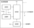
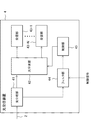
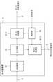
- FIG. 2 is a diagram illustrating a configuration example of the optical transmission device 1.
- the optical transmission apparatus 1 includes a plurality of transmission units 11-1 to 11-N (referred to as “transmission unit 11” if there is no particular need to distinguish), a processing unit 12, and a control unit 13.
- Each of the plurality of transmission units 11-1 to 11-N transmits optical signals having different wavelengths.
- the optical signal transmitted by the transmission unit 11 can include information (data) by, for example, phase modulation.
- At least one of the plurality of optical signals output from the plurality of transmission units 11-1 to 11-N is used as an optical signal for data.
- the wavelength used as the optical signal for data is changed according to customer needs and the occurrence of failures.
- at least one wavelength is assigned to each of the plurality of customers as a wavelength of an optical signal for transmitting information (data).
- the wavelength assigned to the first customer can be changed to another wavelength (for example, an unused wavelength) according to the needs of the first customer.
- the wavelength assigned to the first customer and the wavelength assigned to the second customer can be interchanged.
- the wavelength assigned to the first customer is transmitted to another wavelength (the other transmission unit 11 in which no failure has occurred) in response to the occurrence of a failure in the transmission unit 11 outputting the wavelength. Wavelength).
- the processing unit 12 selects an optical signal having a predetermined wavelength from the plurality of optical signals output from the plurality of transmission units 11, and corresponds to the bit pattern of the control information.
- the intensity of the selected optical signal is modulated.
- the control information is a signal for controlling other devices on the transmission network.
- the control information is a signal that instructs the optical repeater 3 or the optical receiver 4 to change the channel of the optical signal.
- the processing unit 12 multiplexes the plurality of optical signals and outputs them as a wavelength multiplexed optical signal.
- the processing unit 12 can use, for example, a wavelength selective switch described in Japanese Patent No. 4748514.
- the wavelength selective switch can drop a light wave having a desired wavelength from a plurality of inputted light waves.
- the wavelength selective switch can add a light wave having a desired wavelength to a plurality of input light waves, and multiplexes the plurality of input light waves with the added light wave to provide wavelength multiplexed light. It can be output as a signal.
- the wavelength selective switch has an optical waveguide circuit formed on the substrate and a control means for controlling the switching of the light traveling path by applying thermal fluctuations to the optical waveguide circuit, and adds the wavelength of the light wave to be dropped or added. The wavelength of the light wave can be controlled accurately.
- the wavelength selection switch selects an optical signal having a predetermined wavelength from the plurality of optical signals output from the plurality of transmission units 11 and drops (or does not drop) the predetermined wavelength according to the bit pattern of the control information. These optical signals can be used as control signal light.
- the wavelength selective switch when the control information bit is “0” (when the control information bit is “0”), among the plurality of optical signals output from the plurality of transmission units 11, Is dropped, and is not dropped when the bit is “1” (when the control information bit is “1”). That is, the optical signal of the predetermined wavelength exists only when the bit of the control information is “1”. Therefore, the apparatus that receives the wavelength-multiplexed optical signal can decode the bit pattern of the control information by detecting a predetermined wavelength included in the wavelength-multiplexed optical signal.
- the control unit 13 performs control so that the processing unit 12 applies intensity modulation to an optical signal having a predetermined wavelength. Specifically, the control unit 13 notifies the processing unit 12 of a predetermined wavelength used as control signal light among the plurality of optical signals output from the plurality of transmission units 11. And the control part 13 is light of the predetermined
- the processing unit 12 is instructed to drop a part of the signal. The control unit 13 instructs the processing unit 12 to drop the optical signal having the predetermined wavelength in response to the bit pattern of the control information being “0”. On the other hand, when the bit pattern of the control information is “1”, the control unit 13 does not instruct to drop the optical signal having the predetermined wavelength.
- the optical signal of a predetermined wavelength used as the control signal light is an optical signal that is not used as an optical signal for data among the optical signals output from the transmission unit 11.
- the control unit 13 determines a wavelength for control signal light based on a control signal from an external control device (not shown). For example, the external control apparatus notifies the control unit 13 of the wavelength used as the optical signal for data. Based on the notification, the control unit 13 determines at least one of the wavelengths not used for data as a wavelength for control signal light.
- the processing unit 12 since the processing unit 12 has a function of selecting an arbitrary wavelength from the wavelength multiplexed optical signal, even if the wavelength for the control signal light changes, the wavelength used as the control signal light according to the change. Can change. Therefore, in the optical transmission device 1 according to the first embodiment, the wavelength of the optical signal for data is changed according to the customer's needs and the network situation such as the occurrence of a failure, and the wavelength of the control signal light is changed accordingly. Even if it is necessary to do so, it is possible to flexibly cope with the change.
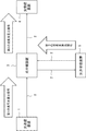
- FIG. 3 is a flowchart showing an operation example of the optical transmission device 1 in the first embodiment of the present invention.
- each of the plurality of transmission units 11-1 to 11-N transmits optical signals having different wavelengths (S101).
- the control unit 13 specifies a predetermined wavelength to be used as control signal light to the processing unit 12 and applies intensity modulation to the optical signal having the predetermined wavelength so as to correspond to the bit pattern of the control information. (S102). Specifically, the control unit 13 instructs the processing unit 12 to drop the optical signal having the predetermined wavelength in response to the bit pattern of the control information being “0”.
- the processing unit 12 selects an optical signal having a predetermined wavelength from the plurality of optical signals output from the plurality of transmission units 11, and corresponds to the bit pattern of the control information.
- the intensity of the selected optical signal is modulated (S103).
- the processing unit 12 modulates the intensity of the selected optical signal, combines the plurality of optical signals, and outputs the multiplexed optical signal as a wavelength multiplexed optical signal (S104).
- the optical transmission device 1 uses the processing unit 12 to select a predetermined wavelength from the plurality of optical signals output from the plurality of transmission units 11 so as to correspond to the bit pattern of the control information. Drop (or don't drop). Accordingly, in the optical transmission device 1, the wavelength of the optical signal for data is changed according to the customer's needs and the situation of the network such as the occurrence of a failure, and accordingly, the wavelength of the control signal light needs to be changed. However, it is possible to respond flexibly to the change.
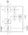
- FIG. 4 is a diagram illustrating a configuration example of the optical repeater 3.
- the optical repeater 3 includes an optical receiver 30, a processor 32, and a controller 33.
- the optical receiver 30 receives the wavelength multiplexed optical signal transmitted from the optical transmitter 1 via the transmission path 2 and outputs it to the processor 32.
- the optical receiving unit 30 may be an optical branching unit.
- the optical branching unit branches the wavelength multiplexed optical signal input from the transmission line 2, outputs one wavelength multiplexed optical signal to the processing unit 32, and transmits the other wavelength multiplexed signal to another external device (for example, To the optical transceiver 5).
- the other wavelength multiplexed optical signal is subjected to a predetermined process in another device (not shown) included in the optical repeater 3 and then output to the optical transmitter / receiver 5.
- the other wavelength-multiplexed optical signal is output to the other optical transceiver 5 as it is when it is not necessary to perform predetermined processing.
- the processing unit 32 selects an optical signal having a predetermined wavelength included in the wavelength multiplexed optical signal, and the light of the selected optical signal so as to correspond to the bit pattern of the notification information. Filter power.
- the processing unit 32 outputs to the transmission line 2 a wavelength division multiplexed optical signal including the optical signal having the predetermined wavelength whose intensity is modulated according to the bit pattern of the notification information.
- the above processing unit 32 has a function of filtering and outputting optical power of a predetermined wavelength included in the wavelength multiplexed optical signal.
- the processing unit 32 uses the optical signal of the predetermined wavelength as the control signal light by dropping (or not dropping) the optical signal of the predetermined wavelength included in the wavelength multiplexed optical signal according to the bit pattern of the notification information. Specifically, the processing unit 32 drops an optical signal having a predetermined wavelength when the bit of the notification information is “0” (while the bit of the notification information is “0”), and the bit is “1”. In the case of (when the bit of the notification information is “1”), it is not dropped.
- the control signal light transmitted by the optical repeater 3 is a signal for notifying the optical receiver 4 of the status (for example, failure status) of the own device.
- the processing unit 32 can use, for example, a wavelength selective switch described in Japanese Patent No. 4748514.
- the wavelength selective switch can demultiplex an input wavelength-multiplexed optical signal into a plurality of light waves having different wavelengths, and can drop a light wave having a desired wavelength among the plurality of demultiplexed light waves. Further, the wavelength selective switch can add a light wave of a desired wavelength to the demultiplexed light waves, and combines the demultiplexed light waves and the added light wave, It can be output as a wavelength multiplexed optical signal.
- the processing unit 32 is a device (for example, the optical receiver 4) that notifies the wavelength-division multiplexed optical signal including the optical signal having a predetermined wavelength that is partially dropped according to the bit pattern of the notification information via the transmission path 2. ).
- the control unit 33 generates notification information for notifying the status (for example, failure status) of the own device.
- the control unit 33 collects a failure status and the like from the devices included in the optical repeater 3 in order to generate the notification information.
- control unit 33 controls the processing unit 32 so as to apply intensity modulation to an optical signal having a predetermined wavelength among the wavelength multiplexed optical signals received by the optical receiving unit 30. Specifically, the control unit 33 determines a predetermined wavelength to be used as control signal light among a plurality of wavelengths included in the wavelength multiplexed optical signal. Then, the control unit 33 instructs the processing unit 32 to drop a part of the optical signal having the predetermined wavelength so as to correspond to the bit pattern of the generated notification information. The control unit 33 instructs the processing unit 32 to drop the optical signal having the predetermined wavelength in response to the bit pattern of the notification information being “0”. When the bit pattern of the notification information is “1”, the control unit 33 does not instruct to drop the optical signal having the predetermined wavelength.
- the optical signal of a predetermined wavelength used as the notification information is an optical signal that is not used as an optical signal for data.
- the control unit 33 determines a wavelength for control signal light based on a control signal from an external control device (not shown).
- the control signal is a signal for notifying the control unit 33 of at least one of optical signals that are not used as data optical signals.
- FIG. 5 is a flowchart showing an operation example of the optical repeater 3 in the second embodiment.
- the optical receiver 30 receives the wavelength multiplexed optical signal input from the transmission path 2 (S201).
- the control unit 33 specifies a predetermined wavelength to be used as control signal light to the processing unit 32, and intensity-modulates the optical signal of the specified predetermined wavelength so as to correspond to the bit pattern of the notification information. (S202). Specifically, the control unit 33 instructs the processing unit 32 to drop the optical signal having the predetermined wavelength in response to the bit pattern of the notification information being “0”.
- the processing unit 32 selects an optical signal having a predetermined wavelength included in the wavelength multiplexed optical signal, and the light of the selected optical signal so as to correspond to the bit pattern of the notification information.
- the power is filtered (S203).
- the processing unit 32 outputs a wavelength-multiplexed optical signal including the optical signal of the predetermined wavelength whose intensity is modulated according to the bit pattern of the notification information to the transmission line 2 (S204).
- the optical repeater 3 uses the processing unit 32 to filter the optical signal having the wavelength selected from the wavelength multiplexed optical signal based on the bit pattern of the notification information, so that the optical signal corresponding to the notification information is obtained. (Control signal light) is included in the wavelength multiplexed optical signal. Therefore, the optical repeater 3 can output the control signal light without providing a light source for control signal light.
- the processing unit 32 of the optical repeater 3 can perform the above-described processing by selecting a predetermined wavelength from the wavelength multiplexed optical signal, the wavelength of the control signal light according to the network environment such as customer needs and the occurrence of a failure. Even if it becomes necessary to change, the change can be flexibly dealt with.
- the configuration example of the optical communication system in the third embodiment is the same as that in FIG.
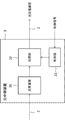
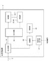
- FIG. 6 is a diagram illustrating a configuration example of the optical transmission device 1.
- the optical transmission device 1 includes a plurality of transmission units 11-1 to 11-N, a processing unit 12, a control unit 13, and an optical output unit 14.
- the optical output unit 14 outputs dummy light for compensating for the change in the intensity of the wavelength multiplexed optical signal for the purpose of making the intensity of the wavelength multiplexed optical signal output from the processing unit 12 constant.
- the light output unit 14 outputs dummy light having a predetermined intensity in response to a request from the control unit 13. For example, an ASE (Amplified Spontaneous Emission) light source can be applied to the light output unit 14.
- the wavelength of the dummy light output from the light output unit 14 is a wavelength other than the wavelengths of the plurality of optical signals output from the transmission units 11-1 to 11-N. That is, the optical output unit 14 outputs dummy light having a wavelength band different from the wavelength band of the data optical signal.
- the control unit 13 instructs the processing unit 12 to drop the optical signal having the predetermined wavelength in response to the bit of the control information being “0”. In this case, the control unit 13 requests the light output unit 14 to output dummy light so as to compensate the dropped optical signal having a predetermined wavelength. Specifically, when the optical signal having the predetermined wavelength is dropped, the control unit 13 outputs dummy light having the same intensity as the dropped optical signal having the predetermined wavelength to the optical output unit 14. Request to do so.
- the optical output unit 14 monitors the intensity of the wavelength multiplexed optical signal output from the processing unit 12, and adjusts the intensity of the dummy light to be output so that the intensity of the wavelength multiplexed optical signal is constant. Also good.
- the processing unit 12 can add a light wave having a desired wavelength to the plurality of optical signals output from the plurality of transmission units 11, the processing unit 12 adds the dummy light input from the light output unit 14 to the plurality of optical signals.
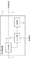
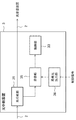
- FIG. 7 is a configuration example of the optical repeater 3 that receives the wavelength multiplexed optical signal output from the optical transmitter 1.
- the optical repeater 3 includes an optical branching unit 31, a control unit 33, and a filter unit 34.
- FIG. 7 shows a configuration example for providing a function for extracting (detecting) the control signal light included in the wavelength multiplexed optical signal in the optical repeater 3, and that other configurations are included. It is not excluded.
- the optical branching unit 31 branches an input wavelength multiplexed optical signal and outputs one wavelength multiplexed optical signal to the filter unit 34 and the other wavelength multiplexed optical signal to another external device (for example, the optical receiving device 4). To do.
- the filter unit 34 transmits only the optical signal having the wavelength for the control signal light among the plurality of optical signals included in the wavelength multiplexed optical signal, outputs the optical signal to the control unit 33, and discards the optical signals having other wavelengths.
- the filter unit 34 receives a control signal that specifies the wavelength of the control signal light, and transmits only the optical signal (that is, the control signal light) having the wavelength specified by the received control signal.
- the control unit 33 decodes the bit pattern of the control information based on the control signal light input from the filter unit 34, and a device (for example, an optical switch, an optical relay, etc.) in the optical repeater 3 based on the control information. ) To control. For example, the control unit 33 requests the optical switch or the optical relay to change the optical path based on the control information.
- a device for example, an optical switch, an optical relay, etc.
- FIG. 8 is a flowchart illustrating an operation example of the optical repeater 3 that receives the wavelength-multiplexed optical signal output from the optical transmitter 1.
- an optical branching unit 31 branches an input wavelength multiplexed optical signal, passes one wavelength multiplexed optical signal to the filter unit 34, and sends the other wavelength multiplexed optical signal to another external device (for example, an optical receiving device). 4) (S301).
- the filter unit 34 transmits only the optical signal having the wavelength for the control signal light out of the plurality of optical signals included in the wavelength multiplexed optical signal, outputs the optical signal to the control unit 33, and discards the optical signals having other wavelengths ( S302).
- the control unit 33 decodes the bit pattern of the control information based on the control signal light input from the filter unit 34, and controls the devices in the optical repeater 3 based on the control information (S303).
- FIG. 9 is a diagram illustrating a configuration example of the optical receiver 4 that receives the wavelength multiplexed optical signal output from the optical transmitter 1 via the optical repeater 3.
- the optical receiver 4 includes an optical branching unit 41, an optical demultiplexing unit 42, receiving units 43-1 to 43-N, a filter unit 44, and a control unit 45.
- the optical branching unit 41 branches the input wavelength multiplexed optical signal, outputs one wavelength multiplexed optical signal to the optical demultiplexing unit 42, and outputs the other wavelength multiplexed optical signal to the filter unit 44.
- the optical demultiplexing unit 42 demultiplexes the input wavelength-multiplexed optical signal, and receives the demultiplexed optical signals to each of the receiving units 43-1 to 43-N in response to a request from the control unit 45. Based on the assigned wavelength, the data is output to each of the receiving units 43-1 to 43-N.
- Each of the receiving units 43-1 to 43-N receives an optical signal having an assigned wavelength.
- the filter unit 44 transmits only the optical signal having the wavelength for the control signal light among the plurality of optical signals included in the input wavelength-multiplexed optical signal, outputs the optical signal to the control unit 45, and outputs the optical signals having other wavelengths. Discard.
- the filter unit 44 receives a control signal designating the wavelength of the control signal light from, for example, an external control device, and transmits only an optical signal having a wavelength designated by the received control signal (that is, control signal light).
- the control unit 45 decodes the bit pattern of the control information based on the control signal light input from the filter unit 44, and controls the devices in the optical receiver 4 based on the control information. For example, the control unit 45 requests the optical demultiplexing unit 42 to change the channel (change of the wavelength assigned to each of the plurality of receiving units 43) based on the control information.
- FIG. 10 is a flowchart showing an operation example of the optical receiver 4 that receives the wavelength multiplexed optical signal output from the optical transmitter 1 via the optical repeater 3.
- FIG. 10 is an operation example when the control unit 45 requests the optical demultiplexing unit 42 to change the channel (change of the wavelength assigned to each of the plurality of receiving units 43).
- the optical branching unit 41 branches the input wavelength multiplexed optical signal, outputs one wavelength multiplexed optical signal to the optical demultiplexing unit 42, and outputs the other wavelength multiplexed optical signal to the filter unit 44 (S401).
- the filter unit 44 transmits only the optical signal having the wavelength for the control signal light among the plurality of optical signals included in the input wavelength-multiplexed optical signal, outputs the optical signal to the control unit 45, and outputs the optical signals having other wavelengths. Discard (S402).
- the control unit 45 decodes the bit pattern of the control information based on the control signal light input from the filter unit 44 (S403).
- the control unit 45 requests the optical demultiplexing unit 42 to change the channel (change of the wavelength assigned to each of the plurality of receiving units 43) based on the decoded control information (S404).
- the optical demultiplexing unit 42 demultiplexes the input wavelength-multiplexed optical signal, and each demultiplexed optical signal is received by each of the plurality of receiving units 43 based on the assignment changed according to the request from the control unit 45. (S405).
- Each of the receiving units 43-1 to 43-N receives an optical signal having an assigned wavelength (S406).
- FIG. 11 is a diagram illustrating another configuration example of the optical repeater 3 that receives the wavelength-multiplexed optical signal output from the optical transmitter 1.
- the optical repeater 3 includes an optical branching unit 31, a control unit 33, a receiving unit 35, and a local light output unit 36.
- the receiving unit 35 causes the input wavelength multiplexed optical signal to interfere with the local light having a predetermined wavelength input from the local light output unit 36, and selectively receives the predetermined wavelength from the wavelength multiplexed optical signal.
- the receiving unit 35 outputs the optical signal having a predetermined wavelength that is selectively received to the control unit 33.
- the receiving unit 35 is, for example, a coherent detection unit that performs coherent detection.
- the coherent detection unit outputs to the control unit 33 a signal in which the wavelength multiplexed signal input from the optical branching unit 31 interferes with local light having a predetermined wavelength input from the local light output unit 36.
- the coherent detection unit includes a 90-degree hybrid mixer (not shown) called a coherent mixer.
- the coherent mixer outputs a signal (interference signal) in which the wavelength multiplexed signal input from the optical branching unit 31 interferes with local light having a predetermined wavelength input from the local light output unit 36.
- the local light output unit 36 outputs local light having a predetermined wavelength based on the received control signal.
- the control signal is a signal that specifies the wavelength of local light output from the local light output unit 36, and the specified wavelength is the wavelength for control signal light.
- the control signal is notified from, for example, the optical transmission device 1 or an external control device (not shown).
- the control signal can be notified to the optical repeater 3 using, for example, a communication path (outbound communication path) provided by a line different from the transmission path 2.
- control signal may be included in the control signal light.
- the control signal is a signal that specifies the wavelength of local light emission after a predetermined time has elapsed.
- the optical transmission device 1 sends a control signal to the control signal in advance to change the wavelength of the local light after the lapse of the predetermined time. It is included in the light and transmitted to the optical repeater 3.
- the optical repeater 3 changes the wavelength of the local light to the wavelength specified by the control signal after a predetermined time specified by the control signal has elapsed.
- the receiving unit 35 causes the input wavelength-multiplexed optical signal and local light having a predetermined wavelength to interfere with each other, and selectively receives a predetermined wavelength from the wavelength-multiplexed optical signal. Therefore, by setting the local light output from the local light output unit 36 as the wavelength for the control signal light, the receiving unit 35 selectively selects only the control signal light from the plurality of optical signals included in the wavelength multiplexed optical signal. The control signal light can be received and output to the control unit 33.
- FIG. 12 shows another configuration example of the optical receiver 4 that receives the wavelength-multiplexed optical signal output from the optical transmitter 1 via the optical repeater 3.
- the optical receiver 4 includes an optical branching unit 41, an optical demultiplexing unit 42, receiving units 43-1 to 43-N, a control unit 45, a receiving unit 46, and a local light output unit 47.
- the receiving unit 46 interferes with the input wavelength multiplexed optical signal and the local light having a predetermined wavelength input from the local light output unit 47, and selectively receives the predetermined wavelength from the wavelength multiplexed optical signal.
- the receiving unit 46 outputs the selectively received optical signal having a predetermined wavelength to the control unit 45.
- the reception unit 46 is a coherent detection unit that performs, for example, coherent detection, similarly to the reception unit 35 of the optical repeater 3 described above.
- the coherent detection unit outputs to the control unit 45 a signal in which the wavelength multiplexed signal input from the optical branching unit 41 interferes with local light having a predetermined wavelength input from the local light output unit 47.
- the local light output unit 47 outputs local light having a predetermined wavelength based on the received control signal.
- the control signal is a signal designating local light having a predetermined wavelength output from the local light output unit 47, and the predetermined wavelength is a wavelength for control signal light.
- the control signal is notified from, for example, the optical transmission device 1 or an external control device (not shown).
- the control signal can be notified to the optical receiver 4 using a communication path (outbound communication path) provided by a line different from the transmission path 2, for example.
- the receiving unit 46 interferes with the input wavelength multiplexed optical signal and the local light of a predetermined wavelength, and selectively receives the predetermined wavelength from the wavelength multiplexed optical signal. Therefore, by using the local light output from the local light output unit 47 as the wavelength for the control signal light, the receiving unit 46 receives only the control signal light from the plurality of optical signals included in the wavelength multiplexed optical signal, The control signal light can be output to the control unit 45.
- the fourth embodiment includes an optical output unit that compensates for an optical signal having a wavelength dropped by the optical repeater 3 using the processing unit 32 with dummy light, and a wavelength multiplexed optical signal output from the optical repeater 3 is provided. The strength is kept constant.
- FIG. 13 is a diagram illustrating a configuration example of the optical repeater 3.
- the optical repeater 3 includes an optical receiving unit 30, a processing unit 32, a control unit 33, and an optical output unit 39.
- the light output unit 39 is, for example, an ASE light source.
- the optical output unit 39 outputs dummy light for compensating for changes in the intensity of the wavelength multiplexed optical signal for the purpose of making the intensity of the wavelength multiplexed optical signal output from the processing unit 32 constant.
- the light output unit 39 outputs dummy light having a predetermined intensity in response to a request from the control unit 33.
- the wavelength of the dummy light output from the optical output unit 39 is a wavelength other than the wavelengths of the plurality of optical signals on which data is superimposed in the wavelength multiplexed optical signal. That is, the optical output unit 39 outputs dummy light having a wavelength band different from the wavelength band of the data optical signal.
- the control unit 33 instructs the processing unit 32 to drop an optical signal having a predetermined wavelength in response to the bit of the notification information being “0”. In this case, the control unit 33 requests the light output unit 39 to output dummy light so as to compensate for the dropped optical signal having a predetermined wavelength. Specifically, when the optical signal of a predetermined wavelength is dropped, the control unit 33 outputs dummy light having the same intensity as the intensity of the dropped optical signal of the predetermined wavelength to the optical output unit 39. Request.
- the optical output unit 39 monitors the intensity of the wavelength multiplexed optical signal output from the processing unit 32 and adjusts the intensity of the dummy light to be output so that the intensity of the wavelength multiplexed optical signal is constant. Also good.
- the processing unit 32 drops an optical signal having a predetermined wavelength from the input wavelength multiplexed optical signal, and the dummy light input from the optical output unit 39 to the dropped wavelength multiplexed optical signal.
- the optical repeater 3 includes the optical output unit 39, and compensates the optical signal having the wavelength dropped by using the processing unit 32 with the dummy light, thereby allowing the wavelength multiplexed optical signal output from the optical repeater 3 to be compensated.
- the strength can be kept constant.
- the optical repeater 3 notifies a control signal for notifying two different optical receivers (for example, the optical receiver 4 and the optical transmitter / receiver 5 in FIG. 1) of its own state. It transmits light.
- FIG. 14 is a diagram illustrating a configuration example of the optical repeater 3.
- the optical repeater 3 in the fifth embodiment includes an optical receiving unit 30, an optical branching unit 31, a first processing unit 32-1, a second processing unit 32-2, and a control unit 33. .
- the optical branching unit 31 branches the wavelength multiplexed optical signal input from the optical receiving unit 30 and outputs the branched optical signal to the first processing unit 32-1 and the second processing unit 32-2.
- the first processing unit 32-1 converts a part of the optical signal having the first predetermined wavelength included in the wavelength multiplexed optical signal into a bit pattern of notification information. Is filtered (dropped) in response to the signal and output to the first optical receiver.
- the first predetermined wavelength is selected from wavelengths not used as the wavelength of the optical signal for data between the optical repeater 3 and the first optical receiver.
- the second processing unit 32-2 converts a part of the optical signal having the second predetermined wavelength included in the wavelength multiplexed optical signal into the notification information. Filter (drop) according to the bit pattern and output to the second optical receiver.
- the second predetermined wavelength is selected from wavelengths not used as data optical signals between the optical repeater 3 and the second optical receiver.
- the control unit 33 designates the first predetermined wavelength used as the control signal light to the first processing unit 32-1, and the first processing unit 32-1 so as to correspond to the bit pattern of the first notification information.
- the optical signal having a predetermined wavelength is to be filtered.
- the first notification information is information for notifying the first optical receiver of the state of the optical repeater 3.
- control unit 33 designates the second predetermined wavelength to be used as the control signal light to the second processing unit 32-2, and corresponds to the bit pattern of the second notification information.
- An instruction to filter the optical signal of the second wavelength is given.
- the second notification information is information for notifying the second optical receiver of the state of the optical repeater 3.
- the optical repeater 3 includes two processing units 32-1 and 32-2, and the two processing units 32-1 and 32-2 each receive two different optical reception units.
- a wavelength-multiplexed optical signal including control signal light is transmitted to an apparatus (for example, the optical receiver 4 and the optical transmitter / receiver 5 in FIG. 1). Therefore, the optical repeater 3 can notify the status of the own apparatus to two different optical receivers.
- the number of processing units 32 included in the optical repeater 3 is not limited to two, and may be any number.
- the optical repeater 3 can transmit the wavelength multiplexed optical signal including the control signal light to the number of optical receivers corresponding to the number of the processing units 32, and can notify the state of the own apparatus.
- the wavelength multiplexed optical signal output from the optical transmission device 1 includes at least one first control signal light
- the wavelength multiplexed optical signal output from the optical repeater 3 includes At least one second control signal light is included.
- the first control signal light includes control information for the optical repeater 3.
- the second control signal light includes notification information for the optical repeater 3 to notify the optical receiver 4 and the optical transmitter / receiver 5 of the state (for example, failure status) of the own apparatus.
- FIG. 15 is a diagram illustrating a configuration example of the optical repeater 3 in the sixth embodiment.
- the optical repeater 3 in the sixth embodiment includes a first optical branching unit 31-1, a second optical branching unit 31-2, a processing unit 32, a control unit 33, and a filter unit 34. .
- the first optical branching unit 31-1 branches the wavelength multiplexed optical signal input from the optical transmission device 1 via the transmission path 2, and sends one wavelength multiplexed optical signal to the second optical branching unit 31-2.
- the other wavelength multiplexed signal is output to another external device (for example, the optical transceiver 5).
- the second optical branching unit 31-2 branches the input wavelength multiplexed optical signal, outputs one wavelength multiplexed optical signal to the processing unit 32, and outputs the other wavelength multiplexed optical signal to the filter unit 34.
- the filter unit 34 receives a control signal that specifies the wavelength of the first control signal light.
- the filter unit 34 transmits and controls only the optical signal having the wavelength specified by the received control signal (that is, the first control signal light) among the plurality of optical signals included in the input wavelength multiplexed optical signal. To the unit 33.
- the control unit 33 generates notification information for notifying the status (for example, failure status) of the own device.
- the control unit 33 collects failure statuses and the like from the devices included in the optical repeater 3 in order to generate notification information.
- the wavelength of the second control signal light for the optical repeater 3 to notify the status of the own apparatus is notified from the optical transmitter 1 by the first control signal light input from the filter unit 34. Therefore, the control unit 33 determines the wavelength of the second control signal light based on the first control signal light.
- the control unit 33 instructs the processing unit 32 to filter the optical power of a part of the second control signal light having a predetermined wavelength so as to correspond to the bit pattern of the generated notification information.
- the optical signal having a predetermined wavelength used as the second control signal light is an optical signal that is not used as an optical signal for data.
- the processing unit 32 selects an optical signal having a predetermined wavelength from among the wavelength multiplexed optical signals input from the second optical branching unit 31-2, and a bit pattern of notification information
- the optical power of the selected optical signal is filtered so as to correspond to.
- the processing unit 32 turns ON / OFF (does not drop / drop) the output of the selected optical signal.
- the processing unit 32 drops a wavelength-multiplexed optical signal including an optical signal having a predetermined wavelength (that is, the second control signal light) dropped (or not dropped) so as to correspond to the bit pattern of the notification information.
- FIG. 16 is a flowchart showing an operation example of the optical repeater 3 in the sixth embodiment of the present invention.
- the first optical branching unit 31-1 branches the wavelength multiplexed optical signal input from the transmission line 2, and outputs one wavelength multiplexed optical signal to the second optical branching unit 31-2.
- the other wavelength multiplexed signal is output to another external device (for example, the optical transceiver 5) (S501).
- the second optical branching unit 31-2 branches the input wavelength multiplexed optical signal, outputs one wavelength multiplexed optical signal to the processing unit 32, and outputs the other wavelength multiplexed optical signal to the filter unit 34 ( S502).
- the filter unit 34 receives a control signal that specifies the wavelength of the first control signal light. Then, the filter unit 34 transmits only the optical signal having the wavelength specified by the received control signal (that is, the first control signal light) among the plurality of optical signals included in the wavelength multiplexed optical signal, and transmits the control unit. It outputs to 33 (S503).
- the control unit 33 decodes the input bit pattern of the first control signal light and, based on the decoded control information, out of the wavelengths of the plurality of optical signals included in the wavelength multiplexed optical signal, the second control signal A predetermined wavelength used as light is determined (S504).
- the control unit 33 generates notification information for notifying the status of the device itself (for example, a failure status), and filters the determined optical power of the predetermined wavelength so as to correspond to the bit pattern of the generated notification information.
- the processing unit 32 is instructed to do so (S505).
- the processing unit 32 outputs a wavelength-multiplexed optical signal including an optical signal (second control signal light) having a predetermined wavelength, which is partially filtered (dropped) according to the bit pattern of the notification information, to the transmission line 2 (S506).
- FIG. 17 is a diagram illustrating another configuration example of the optical repeater 3 in the sixth embodiment.
- the optical repeater 3 includes a first optical branching unit 31-1, a second optical branching unit 31-2, a processing unit 32, a control unit 33, a receiving unit 35, And a local light output unit 36.
- the receiving unit 35 causes the input wavelength multiplexed optical signal to interfere with the local light having a predetermined wavelength input from the local light output unit 36, and selectively receives the predetermined wavelength from the wavelength multiplexed optical signal.
- the receiving unit 35 outputs the optical signal having a predetermined wavelength selectively received to the control unit 33. Therefore, by using the local light output from the local light output unit 36 as the wavelength of the first control signal light, the receiving unit 35 includes the first control information including the control information from the plurality of optical signals included in the wavelength multiplexed optical signal. Only the control signal light can be received and the first control signal light can be output to the control unit 33.
- the optical repeater 3 in the sixth embodiment performs the second control including the notification information on the wavelength specified by the control information included in the first control signal light from the optical transmitter 1.
- the wavelength of the signal light Therefore, in the optical communication system according to the sixth embodiment, the optical transmission device 1 can specify the second control signal light output from the optical repeater 3.
- FIG. 18 is a diagram illustrating a configuration example of an optical communication system according to the seventh embodiment.
- the first wavelength-multiplexed optical signal output from the optical transmission device 1 includes the first control signal light.
- the first control signal light is an optical signal including first control information for the optical transmitter 1 to control the optical repeater 3.
- the second wavelength multiplexed optical signal output from the optical repeater 3 includes the second control signal light.
- the second control signal light is an optical signal including notification information for the optical repeater 3 to notify the status (for example, failure status) of the own device.
- the third wavelength multiplexed optical signal output from the optical transceiver 5 includes the third control signal light.
- the third control signal light is an optical signal including second control information for the optical transceiver 5 to control the optical repeater 3.
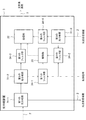
- FIG. 19 is a diagram illustrating a configuration example of the optical repeater 3 in the seventh embodiment.
- the optical repeater 3 includes a first optical branching unit 31-1, a second optical branching unit 31-2, a third optical branching unit 31-3, a processing unit 32, a control unit 33, 1 to 4th filter units 34-1 to 34-4.
- the second optical branching unit 31-2 branches the first wavelength division multiplexed optical signal input from the first optical branching unit 31-1, and one of the first wavelength division multiplexed optical signals is a first filter unit.
- the other first wavelength multiplexed optical signal is output to the third filter unit 34-3.
- the first filter unit 34-1 transmits only the first control signal light included in the first wavelength-multiplexed optical signal output from the optical transmission device 1 in accordance with the control signal, and outputs it to the control unit 33. .
- the third filter unit 34-3 transmits only the optical signal addressed to the optical receiving device 4 out of the optical signal included in the first wavelength-multiplexed optical signal input from the optical transmitting device 1, and transmits it to the processing unit 32. Output.
- the third optical branching unit 31-3 branches the third wavelength-multiplexed optical signal input from the optical transmission / reception device 5, and sends one third wavelength-multiplexed optical signal to the second filter unit 34-2.
- the other third wavelength multiplexed optical signal is output to the fourth filter section 34-4.
- the second filter unit 34-2 transmits only the third control signal light included in the third wavelength-multiplexed optical signal input from the optical transmission / reception device 5 according to the control signal, and outputs it to the control unit 33. To do.
- the fourth filter unit 34-4 transmits only the optical signal addressed to the optical receiving device 4 out of the optical signal included in the third wavelength-multiplexed optical signal input from the optical transmitting / receiving device 5 and transmits it to the processing unit 32. Output.
- the control unit 33 decodes the bit pattern of the first control information from the input first control signal light, and controls the devices in the optical repeater 3 based on the decoded first control information. Similarly, the control unit 33 decodes the bit pattern of the second control information from the input third control signal light, and determines the devices in the optical repeater 3 based on the decoded second control information. Control.
- control unit 33 generates notification information for notifying the status of the device itself (for example, a failure status).
- the control unit 33 collects failure statuses and the like from the devices included in the optical repeater 3 in order to generate notification information.
- the control unit 33 determines the wavelength of the second control signal light based on the first control information decoded from the first control signal light.
- the wavelength of the second control signal light may be notified from the optical transmission / reception device 5.
- the control unit 33 uses the second control signal light based on the second control information decoded from the third control signal light included in the third wavelength-multiplexed optical signal received from the optical transceiver 5. Determine the wavelength.
- the control unit 33 determines the wavelength of the second control signal light based on the first control information decoded from the first control signal light. Then, the control unit 33 instructs the processing unit 32 to drop a part of the determined optical signal having a predetermined wavelength so as to correspond to the generated bit pattern of the notification information.
- the optical signal having a predetermined wavelength used as the second control signal light is an optical signal that is not used as an optical signal for data.
- the processing unit 32 responds to the wavelength multiplexed optical signal input from the third filter unit 34-3, the wavelength multiplexed optical signal input from the fourth filter unit 34-4, and an instruction from the control unit 33.
- the second control signal light having a predetermined wavelength that is partially dropped based on the bit pattern of the notification information is combined and output to the transmission line 2.
- the optical repeater 3 receives not only the first control information decoded from the first control signal light from the optical transmitter 1 but also the third control signal light decoded from the optical transmitter / receiver 5.
- the devices in the optical repeater 3 are controlled based on the control information 2. Therefore, the optical communication system in the seventh embodiment can control the devices in the optical repeater 3 not only from the optical transmitter 1 but also from the optical transmitter / receiver 5.
- the configuration example of the optical communication system in the eighth embodiment is the same as that shown in FIG.
- FIG. 20 is a diagram illustrating a configuration example of the optical transmission device 1 in the eighth embodiment.
- the optical transmission device 1 includes a plurality of transmission units 11-1 to 11-N, an optical multiplexing unit 17, a processing unit 12, a control unit 13, and an optical output unit 14.
- the optical transmission device 1 includes a variable optical attenuator (VOA) 15 and an optical demultiplexing unit 16.
- VOA variable optical attenuator
- the VOA 15 changes the intensity of the input optical signal having a predetermined wavelength in response to a request from the control unit 13.
- a variable optical attenuator described in Japanese Patent No. 5065333 can be used as the VOA 15.
- the variable optical attenuator can attenuate the intensity of the signal light propagating through the optical fiber to an arbitrary light intensity.
- the variable optical attenuator can vary the intensity of the output optical signal according to the magnitude of the applied voltage.
- the variable optical attenuator can change the intensity of the output optical signal in units of microseconds.
- the VOA 15 attenuates the intensity of the optical signal of the predetermined wavelength to “0” when the bit of the control information is “0” (while the bit of the control information is “0”) for the optical signal of the predetermined wavelength. .
- the VOA 15 does not attenuate the intensity of the optical signal of the predetermined wavelength. That is, the optical signal of the predetermined wavelength included in the wavelength multiplexed optical signal does not include the optical signal of the predetermined wavelength when the control information bit is “0” (intensity is “0”), and the bit is “1”. ",
- the optical signal of the predetermined wavelength is included. Therefore, a device (for example, the optical repeater 3) that receives the wavelength multiplexed optical signal can decode the bit pattern of the control information by detecting a predetermined wavelength included in the wavelength multiplexed optical signal.
- the control unit 13 demultiplexes an optical signal having a predetermined wavelength used as control signal light among a plurality of wavelengths included in the wavelength division multiplexed optical signal to the optical demultiplexing unit 16 and inputs the demultiplexed optical signal to the VOA 15. Request.
- control unit 13 instructs the VOA 15 to attenuate (or not attenuate) an optical signal having a predetermined wavelength so as to correspond to the bit pattern of the control information for controlling the optical repeater 3. .
- control unit 13 instructs the VOA 15 to attenuate the optical signal having a predetermined wavelength used as the control signal light
- the control unit 13 indicates that the optical output unit compensates the attenuation of the optical signal having the predetermined wavelength. 14 to request.
- the optical demultiplexing unit 16 demultiplexes an optical signal having a predetermined wavelength designated by the control unit 13 in response to a request from the control unit 13 and inputs the demultiplexed optical signal to the VOA 15.
- the optical demultiplexing unit 16 outputs an optical signal other than the optical signal input to the VOA 15 included in the wavelength multiplexed optical signal to the processing unit 12.
- the processing unit 12 adds the optical signal having a predetermined wavelength input from the VOA 15 and the dummy light input from the optical output unit 14 to the optical signal input from the optical demultiplexing unit 16, and transmits the transmission line 2. Output from.
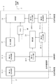
- FIG. 21 is a diagram illustrating a configuration example of the optical repeater 3 according to the eighth embodiment.
- the optical repeater 3 includes a first optical branching unit 31-1, a second optical branching unit 31-2, a third optical branching unit 31-3, a processing unit 32, a control unit 33, 1 filter unit 34-1, second filter unit 34-2, and fourth filter unit 34-4.
- the optical repeater 3 includes an optical demultiplexing unit 37 and a VOA 38.
- the VOA 38 changes the intensity of the input optical signal having a predetermined wavelength in response to a request from the control unit 33. Similar to the VOA 15 in FIG. 20, the variable optical attenuator described in Japanese Patent No. 5065333 can be used as the VOA 38.
- the control unit 33 requests the optical demultiplexing unit 37 to demultiplex an optical signal having a predetermined wavelength used as control signal light among a plurality of wavelengths included in the wavelength multiplexed optical signal and output the demultiplexed optical signal to the VOA 38. To do.
- control unit 33 informs the VOA 38 that the optical signal having a predetermined wavelength is attenuated (or not attenuated) so as to correspond to the bit pattern of the notification information for notifying the state of the optical repeater 3. Instruct.
- the optical demultiplexing unit 37 demultiplexes an optical signal having a predetermined wavelength designated by the control unit 33 in response to a request from the control unit 33 and outputs the demultiplexed optical signal to the VOA 38.
- the optical demultiplexing unit 37 outputs an optical signal other than the optical signal input to the VOA 38 included in the wavelength multiplexed optical signal to the processing unit 32.
- the processing unit 32 includes a wavelength multiplexed optical signal input from the optical demultiplexing unit 37, a wavelength multiplexed optical signal input from the fourth filter unit 34-4, and an optical signal having a predetermined wavelength input from the VOA 38. Are combined and output to the transmission line 2.
- the optical transmitter 1 or the optical repeater 3 includes the VOA 15 or the VOA 38 in which the intensity of the optical signal to be output is variable depending on the magnitude of the applied voltage. Since the VOA 15 or the VOA 38 can change the intensity of the output optical signal in units of microseconds, the intensity of the optical signal having a predetermined wavelength can be changed. Therefore, even if the bit pattern of the control information or the notification information changes at high speed, the optical transmission device 1 or the optical relay device 3 can make the optical signal of a predetermined wavelength correspond to the control information or the notification information. It becomes possible.
- FIG. 22 is a diagram illustrating a configuration example of an optical communication system according to the ninth embodiment.
- the optical communication system includes an optical transmission device 1, a transmission path 2, an optical relay device 3, an optical reception device 4, an optical transmission / reception device 5, and an EMS (Element Management System) 6. Including.
- the configuration example of the optical transmission device 1 in the ninth embodiment is the same as the configuration example of the optical transmission device 1 shown in FIG. 2, FIG. 6, or FIG.
- the configuration example of the optical repeater 3 in the ninth embodiment is the same as that of the optical repeater 3 shown in FIG. 4, FIG. 7, FIG. 11, FIG. 13, FIG. This is the same as the configuration example.
- the configuration example of the optical reception device 4 in the ninth embodiment is the same as the configuration example of the optical reception device 4 illustrated in FIG. 9 or FIG.
- the EMS 6 is a device that performs network management of the optical communication system, and manages wavelengths used as optical signals for data.
- the EMS 6 assigns a predetermined wavelength to each of a plurality of customers as the wavelength of the optical signal for transmitting data. Further, the EMS 6 changes the assigned predetermined wavelength in accordance with, for example, customer needs or occurrence of a failure.
- the EMS 6 notifies the control unit 13 of the optical transmission device 1 of the wavelength of the optical signal used as control information by the control signal.
- the control unit 13 of the optical transmitter 1 drops (or does not drop) an optical signal having a predetermined wavelength specified by the control signal in accordance with a bit pattern of control information for controlling the optical repeater 3. To the processing unit 12.
- the EMS 6 notifies the filter unit 34, the first filter unit 34-1 or the local light output unit 36 of the optical repeater 3 of the wavelength of the optical signal used as control information by the optical transmission device 1 by the control signal. To do.
- the EMS 6 notifies the second filter unit 34-2 of the optical repeater 3 of the wavelength of the optical signal used as control information by the optical transmitter / receiver 5.
- the filter unit 34, the first filter unit 34-1 or the second filter unit 34-2 of the optical repeater 3 can only perform the optical signal having the wavelength specified by the control signal. Transparent.
- the local light output unit 36 of the optical repeater 3 outputs local light of a predetermined wavelength specified by the control signal based on the control signal notified from the EMS 6.
- the EMS 6 notifies the control unit 33 of the optical repeater 3 of the wavelength of the control signal light used by the optical repeater 3 to notify the state of the own apparatus.
- the control unit 33 of the optical repeater 3 drops the optical signal having a predetermined wavelength designated by the control signal notified from the EMS 6 in accordance with the bit pattern of the notification information for notifying the status of the own device ( (Or not to drop) to the processing unit 32.
- the EMS 6 notifies the filter unit 44 or the local light output unit 47 of the optical receiver 4 of the wavelength of the optical signal used as control information or notification information.
- the filter unit 44 of the optical receiver 4 transmits only an optical signal having a wavelength specified by the control signal based on the control signal notified from the EMS 6.
- the local light output unit 47 of the optical receiver 4 outputs local light having a predetermined wavelength specified by the control signal based on the control signal notified from the EMS 6.
- the EMS 6 since the EMS 6 centrally manages the wavelength used as the control signal light and notifies each device of the wavelength used as the control signal light, it responds to customer needs and occurrence of failures. Thus, the wavelength can be flexibly changed.
- the computer, CPU (Central Processing Unit) or MPU (Micro-Processing Unit) of the optical transmitter 1 or the optical repeater 3 is software (program) that implements the functions of the above-described embodiments.
- the device that executes the software (program) is not limited to the optical transmission device 1 or the optical relay device 3, and may be any device.
- the optical transmission device 1 or the optical repeater 3 is software (for example) that realizes the functions of the above-described embodiments via various storage media such as a CD-R (Compact Disc Recordable) or a network. Program).
- a program acquired by the optical transmitter 1 or the optical repeater 3 or a storage medium storing the program constitutes the present invention.
- the software (program) may be stored in advance in a predetermined storage unit included in the optical transmission device 1 or the optical repeater 3, for example.
- the computer, CPU, MPU or the like of the optical transmitter 1 or the optical repeater 3 reads out and executes the program code of the acquired software (program).
- the present invention can be applied to applications such as a program for realizing the computer, CPU or MPU of the optical transmitter 1 or the optical repeater 3.
- An optical receiver for receiving a wavelength-multiplexed optical signal;
- a processing unit capable of filtering and outputting optical power of a predetermined wavelength included in the wavelength-multiplexed optical signal;
- a control unit for controlling the processing unit to apply intensity modulation to the optical signal of the predetermined wavelength among the wavelength multiplexed optical signals received by the optical receiving unit;
- An optical repeater for controlling the processing unit to apply intensity modulation to the optical signal of the predetermined wavelength among the wavelength multiplexed optical signals received by the optical receiving unit.
- Appendix 2 The optical repeater according to appendix 1, wherein the control unit controls the processing unit to modulate the intensity of the optical signal having the predetermined wavelength based on control information for another device on a transmission network.
- the control unit modulates the intensity of an optical signal used to transmit control information to another device on a transmission network among a plurality of optical signals included in the wavelength multiplexed optical signal.
- Appendix 4 The optical repeater according to any one of appendices 1 to 3, wherein the control unit specifies a wavelength to be subjected to the intensity modulation in accordance with an external control signal.
- Appendix 6 A light output unit that outputs light of a predetermined wavelength to the processing unit; The optical repeater according to any one of appendices 1 to 5, wherein the processing unit combines and outputs the plurality of optical signals and output light from the optical output unit.
- Appendix 7 A branching unit that branches the wavelength-multiplexed optical signal received by the optical receiving unit into a first branched light output to the first receiving device side and a second branched light output to the second receiving device side;
- the optical repeater according to any one of appendices 1 to 6, wherein the processing unit applies the intensity modulation to at least one of the first or second branched light.
- Appendix 8 A plurality of transmitters that output optical signals of different wavelengths, which can be used for data communication; A processing unit that combines a plurality of optical signals output from the plurality of transmission units and outputs the multiplexed signal as a wavelength multiplexed optical signal; A control unit that controls the processing unit to apply intensity modulation to an optical signal having a predetermined wavelength; and An optical communication device that executes predetermined processing based on control information included in the optical signal of the predetermined wavelength; An optical communication device that executes predetermined processing based on control information included in the optical signal of the predetermined wavelength; An optical communication system including:
- Appendix 9 9. The optical communication system according to appendix 8, wherein the control unit controls the processing unit to modulate the intensity of the optical signal having the predetermined wavelength based on control information for the optical receiver.
- the control unit responds to the processing unit with respect to an optical signal of the predetermined wavelength used for transmitting the control information to the optical communication device among a plurality of optical signals included in the wavelength multiplexed optical signal.
- Appendix 11 A control device for notifying the optical repeater of a control signal designating the predetermined wavelength; 11. The optical communication system according to any one of appendices 8 to 10, wherein the optical repeater specifies the predetermined wavelength to be subjected to the intensity modulation in accordance with a control signal from the controller.
- Appendix 12 Receives wavelength multiplexed optical signal, Of the received wavelength multiplexed optical signal, control to apply intensity modulation to the optical signal of the predetermined wavelength, An optical communication method characterized in that, based on the control, optical power of a predetermined wavelength included in the wavelength-multiplexed optical signal is filtered and output.
- Appendix 13 13 The optical communication method according to appendix 12, wherein the optical signal having the predetermined wavelength is controlled to be intensity-modulated based on control information for another device on the transmission network.
- Appendix 14 Of the plurality of optical signals included in the wavelength-multiplexed optical signal, control is performed so that intensity modulation is performed on an optical signal used for transmitting control information to another device on a transmission network. 14. The optical communication method according to appendix 12 or 13.
- Appendix 15 15. The optical communication method according to any one of appendices 12 to 14, wherein a wavelength to be subjected to the intensity modulation is specified according to a control signal from the outside.
- Appendix 16 16. The optical communication method according to any one of appendices 12 to 15, wherein the intensity modulation is performed by filtering an optical power of the optical signal having the predetermined wavelength.
- Appendix 18 Branching the wavelength-multiplexed optical signal into a first branched light output to the first receiver side and a second branched light output to the second receiver side; 18. The optical communication method according to any one of appendices 12 to 17, wherein the intensity modulation is applied to at least one of the first or second branched light.
- Appendix 19 Receives wavelength multiplexed optical signal, Of the received wavelength multiplexed optical signal, control to apply intensity modulation to the optical signal of the predetermined wavelength, An optical communication method characterized in that, based on the control, optical power of a predetermined wavelength included in the wavelength-multiplexed optical signal is filtered and output.
- Appendix 20 A process of receiving a wavelength-multiplexed optical signal; A process of controlling the optical signal of the predetermined wavelength among the received wavelength-multiplexed optical signals to perform intensity modulation; A program for causing a computer to execute processing for filtering and outputting optical power of a predetermined wavelength included in the wavelength-multiplexed optical signal based on the control.
- Appendix 21 The program according to appendix 20, wherein the program includes a process of controlling the optical signal of the predetermined wavelength to be intensity-modulated based on control information for another device on the transmission network.
- Appendix 22 Including a process of controlling the optical signal used for transmitting control information to another device on the transmission network among the plurality of optical signals included in the wavelength-multiplexed optical signal so as to perform intensity modulation.
- Appendix 23 23.
- Appendix 24 24.
- Appendix 25 Processing for outputting light of the predetermined wavelength; 25.
- Appendix 26 A process of branching the wavelength-multiplexed optical signal into a first branched light output to the first receiver and a second branched light output to the second receiver; 26.
- the present invention can be widely applied to an optical communication system that transmits and receives a control optical signal including control information superimposed on a wavelength multiplexed optical signal.
- SYMBOLS 1 Optical transmitter 2 Transmission path 3
- Optical repeater 4 Optical receiver 5
- Optical transmitter / receiver 6 EMS 11, 11-1, 11-N Transmission unit 12 Processing unit 13
- Control unit 14 Optical output unit 15
- VOA 16 Optical demultiplexing unit 17
- Optical multiplexing unit 30 Optical receiving unit 31 Optical branching unit 31-1 First optical branching unit 31-2 Second optical branching unit 31-3 Third optical branching unit 32 WSS 32-1 First Processing Unit 32-2 Second Processing Unit 33
- Third Filter Unit 34-4 First 4 filter section 35 receiving section 36 local light output section 37 optical demultiplexing section 38 VOA 39 Light output section
Landscapes
- Engineering & Computer Science (AREA)
- Computer Networks & Wireless Communication (AREA)
- Signal Processing (AREA)
- Physics & Mathematics (AREA)
- Electromagnetism (AREA)
- Optical Communication System (AREA)
Abstract
Description
本発明の第1の実施形態の概要について、図面を参照して説明する。なお、この概要に付記した図面参照符号は、理解を助けるための一例として各要素に便宜上付記したものであり、この概要の記載はなんらの限定を意図するものではない。
第2の実施形態の概要について、図面を参照して説明する。第2の実施形態における光通信システムの構成例は、図1と同様である。図4は、光中継装置3の構成例を示す図である。光中継装置3は、光受信部30と、処理部32と、制御部33とを備える。
第3の実施形態の概要について、図面を参照して説明する。なお、第3の実施形態において、第1の実施形態及び第2の実施形態と同様の構成については、説明を省略する。
第4の実施形態の概要について、図面を参照して説明する。なお、第4の実施形態において、第1乃至第3の実施形態と同様の構成については、説明を省略する。
第5の実施形態の概要について、図面を参照して説明する。なお、第5の実施形態において、第1乃至第4の実施形態と同様の構成については、説明を省略する。
第6の実施形態の概要について、図面を参照して説明する。なお、第6の実施形態において、第1乃至第5の各実施形態と同様の構成については、説明を省略する。
第7の実施形態の概要について、図面を参照して説明する。なお、第7の実施形態において、第1乃至第6の各実施形態と同様の構成については、説明を省略する。
第8の実施形態の概要について、図面を参照して説明する。なお、第8の実施形態において、第1乃至第7の各実施形態と同様の構成については、説明を省略する。
第9の実施形態について、図面を参照して説明する。図22は、第9の実施形態における光通信システムの構成例を示す図である。図22に示すように、光通信システムは、光送信装置1と、伝送路2と、光中継装置3と、光受信装置4と、光送受信装置5と、EMS(Element Management System)6とを含む。
第10の実施形態について説明する。第10の実施形態において、光送信装置1又は光中継装置3のコンピュータ、CPU(Central Processing Unit)又はMPU(Micro-Processing Unit)等は、上述した各実施形態の機能を実現するソフトウェア(プログラム)を実行する。なお、第10の実施形態において、該ソフトウェア(プログラム)を実行する装置は、光送信装置1又は光中継装置3に限られず、どのような装置であってもよい。
波長多重光信号を受信する光受信部と、
前記波長多重光信号に含まれる所定の波長の光パワーをフィルタして出力可能である処理部と、
前記処理部が、前記光受信部が受信した前記波長多重光信号のうち、前記所定の波長の光信号に対して強度変調をかけるように制御する制御部と、
を備える光中継装置。
前記制御部は、前記処理部が前記所定の波長の光信号を伝送ネットワーク上の他の装置に対する制御情報に基づいて強度変調するように制御することを特徴とする付記1に記載の光中継装置。
前記制御部は、前記処理部に対し、前記波長多重光信号に含まれる複数の光信号のうち、伝送ネットワーク上の他の装置に制御情報を送信するために使用する光信号に対して強度変調をかけるように制御することを特徴とする付記1又は2に記載の光中継装置。
前記制御部は、外部からの制御信号に応じて、前記強度変調をかける波長を特定することを特徴とする付記1乃至3のいずれかに記載の光中継装置。
前記処理部は、前記所定の波長の光信号の光パワーをフィルタすることにより、前記強度変調をかけることを特徴とする付記1乃至4のいずれかに記載の光中継装置。
前記処理部に対して所定の波長の光を出力する光出力部をさらに備え、
前記処理部は、前記複数の光信号と前記光出力部からの出力光を合波して出力することを特徴とする付記1乃至5のいずれかに記載の光中継装置。
前記光受信部が受信した前記波長多重光信号を第1の受信装置側に出力される第1の分岐光と第2の受信装置側に出力される第2の分岐光に分岐する分岐部をさらに備え、
前記処理部は、前記第1又は第2の分岐光の少なくともいずれか一方について前記強度変調をかける
ことを特徴とする付記1乃至6のいずれかに記載の光中継装置。
データ通信に使用可能である、互いに異なる波長の光信号を出力する複数の送信部と、
前記複数の送信部から出力される複数の光信号を合波して波長多重光信号として出力する処理部と、
前記処理部が所定の波長の光信号に対して強度変調をかけるように制御する制御部と、を備える光送信装置と、
前記所定の波長の光信号に含まれる制御情報に基づいて、所定の処理を実行する光通信装置と、
前記所定の波長の光信号に含まれる制御情報に基づいて、所定の処理を実行する光通信装置と、
を含む光通信システム。
前記制御部は、前記処理部が前記所定の波長の光信号を前記光受信装置に対する制御情報に基づいて強度変調するように制御することを特徴とする付記8に記載の光通信システム。
前記制御部は、前記処理部に対し、前記波長多重光信号に含まれる複数の光信号のうち、前記光通信装置に前記制御情報を送信するために使用する前記所定の波長の光信号に対して強度変調をかけるように制御することを特徴とする付記8又は9に記載の光通信システム。
前記光中継装置に対して、前記所定の波長を指定する制御信号を通知する制御装置をさらに含み、
前記光中継装置は、前記制御装置からの制御信号に応じて、前記強度変調をかける前記所定の波長を特定することを特徴とする付記8乃至10のいずれかに記載の光通信システム。
波長多重光信号を受信し、
受信した前記波長多重光信号のうち、前記所定の波長の光信号に対して強度変調をかけるように制御し、
前記制御に基づいて、前記波長多重光信号に含まれる所定の波長の光パワーをフィルタして出力する
ことを特徴とする光通信方法。
前記所定の波長の光信号を伝送ネットワーク上の他の装置に対する制御情報に基づいて強度変調するように制御することを特徴とする付記12に記載の光通信方法。
前記波長多重光信号に含まれる複数の光信号のうち、伝送ネットワーク上の他の装置に制御情報を送信するために使用する光信号に対して強度変調をかけるように制御することを特徴とする付記12又は13に記載の光通信方法。
外部からの制御信号に応じて、前記強度変調をかける波長を特定することを特徴とする付記12乃至14のいずれかに記載の光通信方法。
前記所定の波長の光信号の光パワーをフィルタすることにより、前記強度変調をかけることを特徴とする付記12乃至15のいずれかに記載の光通信方法。
前記所定の波長の光を出力し、
前記複数の光信号と、前記所定の波長の光を合波して出力する
ことを特徴とする付記12乃至16のいずれかに記載の光通信方法。
前記波長多重光信号を第1の受信装置側に出力される第1の分岐光と第2の受信装置側に出力される第2の分岐光に分岐し、
前記第1又は第2の分岐光の少なくともいずれか一方について前記強度変調をかける
ことを特徴とする付記12乃至17のいずれかに記載の光通信方法。
波長多重光信号を受信し、
受信した前記波長多重光信号のうち、前記所定の波長の光信号に対して強度変調をかけるように制御し、
前記制御に基づいて、前記波長多重光信号に含まれる所定の波長の光パワーをフィルタして出力する
ことを特徴とする光通信方法。
波長多重光信号を受信する処理と、
受信した前記波長多重光信号のうち、前記所定の波長の光信号に対して強度変調をかけるように制御する処理と、
前記制御に基づいて、前記波長多重光信号に含まれる所定の波長の光パワーをフィルタして出力する処理と
をコンピュータに実行させることを特徴とするプログラム。
前記所定の波長の光信号を伝送ネットワーク上の他の装置に対する制御情報に基づいて強度変調するように制御する処理を含むことを特徴とする付記20に記載のプログラム。
前記波長多重光信号に含まれる複数の光信号のうち、伝送ネットワーク上の他の装置に制御情報を送信するために使用する光信号に対して強度変調をかけるように制御する処理を含むことを特徴とする付記20又は21に記載のプログラム。
外部からの制御信号に応じて、前記強度変調をかける波長を特定する処理を含むことを特徴とする付記20乃22のいずれかに記載のプログラム。
前記所定の波長の光信号の光パワーをフィルタすることにより、前記強度変調をかける処理を含むことを特徴とする付記20乃至23のいずれかに記載のプログラム。
前記所定の波長の光を出力する処理と、
前記複数の光信号と、前記所定の波長の光を合波して出力する処理と
を含むことを特徴とする付記20乃至24のいずれかに記載のプログラム。
前記波長多重光信号を第1の受信装置側に出力される第1の分岐光と第2の受信装置側に出力される第2の分岐光に分岐する処理と、
前記第1又は第2の分岐光の少なくともいずれか一方について前記強度変調をかける処理と
を含むことを特徴とする付記20乃至25のいずれかに記載のプログラム。
2 伝送路
3 光中継装置
4 光受信装置
5 光送受信装置
6 EMS
11、11-1、11-N 送信部
12 処理部
13 制御部
14 光出力部
15 VOA
16 光分波部
17 光合波部
30 光受信部
31 光分岐部
31-1 第1の光分岐部
31-2 第2の光分岐部
31-3 第3の光分岐部
32 WSS
32-1 第1の処理部
32-2 第2の処理部
33 制御部
34 フィルタ部
34-1 第1のフィルタ部
34-2 第2のフィルタ部
34-3 第3のフィルタ部
34-4 第4のフィルタ部
35 受信部
36 局発光出力部
37 光分波部
38 VOA
39 光出力部
Claims (15)
- 波長多重光信号を受信する光受信手段と、
第1の波長を指定すると共に通知情報を出力する制御手段と、
前記受信された波長多重光信号から前記第1の波長の光信号を選択して前記通知情報に応じた強度変調を施し、当該強度変調した光信号を前記波長多重光信号に戻して出力する処理手段と、
を備える光中継装置。 - 前記処理手段は、前記第1の波長の光信号の光パワーを前記通知情報に応じてフィルタすることにより、前記強度変調を施すことを特徴とする請求項1に記載の光中継装置。
- 前記処理手段は、前記指定された波長の光信号の光パワーを前記制御情報に応じて減衰する可変光減衰器を含む、請求項2に記載の光中継装置。
- 前記第1の波長の光信号の、前記フィルタによる光強度変化を補償するための、前記第1の波長とは異なる波長を有するダミー光を生成して前記処理手段に出力する光出力手段をさらに備えることを特徴とする請求項2又は3に記載の光中継装置。
- 前記制御手段は、自装置の状態を通知するための通知情報を出力することを特徴とする請求項1乃至4のいずれか1項に記載の光中継装置。
- 前記制御手段は、外部から入力された制御信号に応じて、前記第1の波長を指定することを特徴とする請求項1乃至5のいずれか1項に記載の光中継装置。
- 前記受信された波長多重光信号を分岐し、一方の波長多重光信号を外部に出力すると共に他方の波長多重光信号を前記処理手段に出力する分岐手段をさらに備えることを特徴とする請求項1乃至6のいずれか1項に記載の光中継装置。
- 前記波長多重光信号は、制御情報に応じた強度変調が施された第2の波長の光信号と、前記第2の波長とは異なる波長を有する複数の光信号と、が重畳されたものであり、
前記処理手段は、入力された制御信号に基づいて、前記受信された波長多重光信号から前記第2の波長の光信号を抽出し、
前記制御手段は、前記抽出された第2の波長の光信号から前記制御情報を取得し、取得した制御情報に基づいて所定の制御を行う、
請求項1乃至7のいずれか1項に記載の光中継装置。 - 前記制御情報は、前記第1の波長を指定する情報であり、
前記制御手段は、取得した制御情報に基づいて前記第1の波長を指定する、
請求項8に記載の光中継装置。 - データ通信に使用可能である、互いに異なる波長の光信号をそれぞれ出力する複数の送信手段、および、
前記出力された複数の光信号を合波して波長多重光信号として送信する送信側処理手段、
を備える光送信装置と、
前記波長多重光信号を受信する光受信手段、
第1の波長を指定すると共に通知情報を出力する受信側制御手段、および、
前記受信された波長多重光信号から前記第1の波長の光信号を選択して前記通知情報に応じた強度変調を施し、当該強度変調した光信号を前記波長多重光信号に戻して出力する受信側処理手段、
を備える光中継装置と、
を含む光通信システム。 - 前記光送信装置は、
第2の波長を指定すると共に制御情報を出力する送信側制御手段をさらに備え、
送信側処理手段は、前記出力された複数の光信号から前記第2の波長の光信号を選択して前記制御情報に応じた強度変調を施し、選択されなかった複数の光信号と合波して波長多重光信号として送信し、
前記受信側処理手段は、前記受信された波長多重光信号から前記第2の波長の光信号を抽出し、
前記受信側制御手段は、前記抽出された第2の波長の光信号から前記制御情報を取得し、取得した制御情報に基づいて所定の制御を行う、
請求項10に記載の光通信システム。 - 前記送信側制御手段は、前記光中継装置を制御するための制御情報を出力し、
前記受信側制御手段は、自装置の状態を通知するための通知情報を出力する、
請求項11に記載の光通信システム。 - 前記第2の波長を指定するための制御信号を送信する制御装置をさらに含み、
前記送信側制御手段および受信側処理手段は、受信された前記制御信号に応じて前記第2の波長を特定し、
前記受信側制御手段は、前記取得した制御情報に基づいて前記第1の波長を特定する、
請求項11または12に記載の光通信システム。 - 波長多重光信号を受信し、
第1の波長を指定すると共に通知情報を出力し、
前記受信された波長多重光信号から前記第1の波長の光信号を選択して前記通知情報に応じた強度変調を施し、当該強度変調した光信号を前記波長多重光信号に戻して出力する、
光中継方法。 - 光中継装置のコンピュータに、
波長多重光信号を受信する処理と、
第1の波長を指定すると共に通知情報を出力する処理と、
前記受信された波長多重光信号から前記第1の波長の光信号を選択して前記通知情報に応じた強度変調を施し、当該強度変調した光信号を前記波長多重光信号に戻して出力する処理と、
を実行させるためのプログラムを記憶した、
前記コンピュータが読み取り可能な記憶媒体。
Priority Applications (4)
| Application Number | Priority Date | Filing Date | Title |
|---|---|---|---|
| CN201580016667.3A CN106134102B (zh) | 2014-03-27 | 2015-02-27 | 光学中继器设备、光学通信系统、以及光学中继方法 |
| US15/128,374 US9912407B2 (en) | 2014-03-27 | 2015-02-27 | Optical relay device, optical communication system, optical relay method, and storage medium |
| JP2016509956A JP6288246B2 (ja) | 2014-03-27 | 2015-02-27 | 光中継装置、光通信システム、光中継方法 |
| EP15767821.0A EP3125445B1 (en) | 2014-03-27 | 2015-02-27 | Optical relay device, optical communication system, optical relay method, and storage medium |
Applications Claiming Priority (2)
| Application Number | Priority Date | Filing Date | Title |
|---|---|---|---|
| JP2014-065013 | 2014-03-27 | ||
| JP2014065013 | 2014-03-27 |
Publications (1)
| Publication Number | Publication Date |
|---|---|
| WO2015145985A1 true WO2015145985A1 (ja) | 2015-10-01 |
Family
ID=54194541
Family Applications (1)
| Application Number | Title | Priority Date | Filing Date |
|---|---|---|---|
| PCT/JP2015/001037 Ceased WO2015145985A1 (ja) | 2014-03-27 | 2015-02-27 | 光中継装置、光通信システム、光中継方法及び記憶媒体 |
Country Status (5)
| Country | Link |
|---|---|
| US (1) | US9912407B2 (ja) |
| EP (1) | EP3125445B1 (ja) |
| JP (1) | JP6288246B2 (ja) |
| CN (1) | CN106134102B (ja) |
| WO (1) | WO2015145985A1 (ja) |
Cited By (5)
| Publication number | Priority date | Publication date | Assignee | Title |
|---|---|---|---|---|
| WO2019082862A1 (ja) * | 2017-10-26 | 2019-05-02 | 日本電気株式会社 | 光伝送装置及び光伝送方法 |
| WO2020179182A1 (ja) * | 2019-03-04 | 2020-09-10 | 日本電気株式会社 | 光合分波装置、光海底ケーブルシステム、光合分波方法及び非一時的なコンピュータ可読媒体 |
| JPWO2019065354A1 (ja) * | 2017-09-29 | 2020-11-05 | 日本電気株式会社 | 光増幅装置および光増幅方法 |
| JPWO2021049099A1 (ja) * | 2019-09-10 | 2021-03-18 | ||
| WO2023002599A1 (ja) * | 2021-07-21 | 2023-01-26 | 日本電気株式会社 | 光伝送システム、光装置、および光処理方法 |
Families Citing this family (2)
| Publication number | Priority date | Publication date | Assignee | Title |
|---|---|---|---|---|
| US10135218B2 (en) * | 2015-10-02 | 2018-11-20 | Ayar Labs, Inc. | Multi-wavelength laser system for optical data communication links and associated methods |
| JP7063329B2 (ja) * | 2017-05-11 | 2022-05-09 | 日本電気株式会社 | 光中継器、光中継器の制御方法、及び光伝送システム |
Citations (5)
| Publication number | Priority date | Publication date | Assignee | Title |
|---|---|---|---|---|
| JPH0983434A (ja) * | 1995-09-12 | 1997-03-28 | Tokyo Electric Power Co Inc:The | 光通信システム |
| JP2003032192A (ja) * | 2001-07-16 | 2003-01-31 | Fujitsu Ltd | 光伝送システム |
| JP2003218804A (ja) * | 2002-01-18 | 2003-07-31 | Fujitsu Ltd | ラマン増幅器および波長多重光通信システム、並びに、ラマン増幅の制御方法 |
| JP2008521539A (ja) * | 2004-12-01 | 2008-06-26 | ギブン イメージング エルティーディー | 自律式生体内装置内における双方向通信 |
| JP2008148286A (ja) * | 2006-12-08 | 2008-06-26 | General Instrument Corp | 受動光ネットワークで使用するための光増幅器を制御する方法および装置 |
Family Cites Families (10)
| Publication number | Priority date | Publication date | Assignee | Title |
|---|---|---|---|---|
| JPH098773A (ja) | 1995-06-23 | 1997-01-10 | Hitachi Ltd | 波長監視方式 |
| US6411411B1 (en) * | 1998-03-20 | 2002-06-25 | Fujitsu Limited | Optical wavelength selective control apparatus |
| JP2000241782A (ja) * | 1999-02-19 | 2000-09-08 | Fujitsu Ltd | 可変波長選択フィルタおよび分岐・挿入装置 |
| JP4543210B2 (ja) * | 2004-05-20 | 2010-09-15 | 三菱電機株式会社 | 海底観測装置および海底観測システム |
| US20080193139A1 (en) | 2004-12-01 | 2008-08-14 | Ido Bettesh | Two-Way Communication in an Autonomous in Vivo Device |
| JP4465458B2 (ja) * | 2005-09-20 | 2010-05-19 | 独立行政法人情報通信研究機構 | 位相制御光fsk変調器 |
| JP2010081297A (ja) | 2008-09-26 | 2010-04-08 | Kddi Corp | 全光ネットワーク運用管理装置 |
| JP5435223B2 (ja) * | 2009-10-13 | 2014-03-05 | 日本電気株式会社 | 波長分割多重伝送装置およびその信号光監視方法 |
| JP2012181349A (ja) * | 2011-03-01 | 2012-09-20 | Nec Corp | 分布ラマン増幅装置、分布ラマン増幅方法及び分布ラマン増幅プログラム |
| JP2013046166A (ja) | 2011-08-23 | 2013-03-04 | Hitachi Ltd | 光伝送装置 |
-
2015
- 2015-02-27 US US15/128,374 patent/US9912407B2/en active Active
- 2015-02-27 CN CN201580016667.3A patent/CN106134102B/zh active Active
- 2015-02-27 JP JP2016509956A patent/JP6288246B2/ja active Active
- 2015-02-27 EP EP15767821.0A patent/EP3125445B1/en active Active
- 2015-02-27 WO PCT/JP2015/001037 patent/WO2015145985A1/ja not_active Ceased
Patent Citations (5)
| Publication number | Priority date | Publication date | Assignee | Title |
|---|---|---|---|---|
| JPH0983434A (ja) * | 1995-09-12 | 1997-03-28 | Tokyo Electric Power Co Inc:The | 光通信システム |
| JP2003032192A (ja) * | 2001-07-16 | 2003-01-31 | Fujitsu Ltd | 光伝送システム |
| JP2003218804A (ja) * | 2002-01-18 | 2003-07-31 | Fujitsu Ltd | ラマン増幅器および波長多重光通信システム、並びに、ラマン増幅の制御方法 |
| JP2008521539A (ja) * | 2004-12-01 | 2008-06-26 | ギブン イメージング エルティーディー | 自律式生体内装置内における双方向通信 |
| JP2008148286A (ja) * | 2006-12-08 | 2008-06-26 | General Instrument Corp | 受動光ネットワークで使用するための光増幅器を制御する方法および装置 |
Non-Patent Citations (2)
| Title |
|---|
| MANISH SHARMA ET AL.: "WDM Ring Network Using a Centralized Multiwavelength Light Source and Add-Drop Multiplexing Filters", IEEE JOURNAL OF LIGHTWAVE TECHNOLOGY, vol. 15, no. 6, June 1997 (1997-06-01), pages 917 - 929, XP000700600 * |
| See also references of EP3125445A4 * |
Cited By (15)
| Publication number | Priority date | Publication date | Assignee | Title |
|---|---|---|---|---|
| JPWO2019065354A1 (ja) * | 2017-09-29 | 2020-11-05 | 日本電気株式会社 | 光増幅装置および光増幅方法 |
| US11057110B2 (en) | 2017-10-26 | 2021-07-06 | Nec Corporation | Optical transmission device and optical transmission method |
| WO2019082862A1 (ja) * | 2017-10-26 | 2019-05-02 | 日本電気株式会社 | 光伝送装置及び光伝送方法 |
| JPWO2019082862A1 (ja) * | 2017-10-26 | 2020-10-22 | 日本電気株式会社 | 光伝送装置及び光伝送方法 |
| US11664891B2 (en) | 2019-03-04 | 2023-05-30 | Nec Corporation | Optical multiplexer/demultiplexer, optical submarine cable system, optical multiplexing/demultiplexing method, and non-transitory computer readable medium |
| JPWO2020179182A1 (ja) * | 2019-03-04 | 2021-12-09 | 日本電気株式会社 | 光合分波装置、光海底ケーブルシステム、光合分波方法及びプログラム |
| JP7168064B2 (ja) | 2019-03-04 | 2022-11-09 | 日本電気株式会社 | 光合分波装置、光海底ケーブルシステム、光合分波方法及びプログラム |
| WO2020179182A1 (ja) * | 2019-03-04 | 2020-09-10 | 日本電気株式会社 | 光合分波装置、光海底ケーブルシステム、光合分波方法及び非一時的なコンピュータ可読媒体 |
| WO2021049099A1 (ja) | 2019-09-10 | 2021-03-18 | 日本電気株式会社 | 海底光通信システム、監視結果の伝達方法及び監視プログラムが格納された非一時的なコンピュータ可読媒体 |
| JPWO2021049099A1 (ja) * | 2019-09-10 | 2021-03-18 | ||
| JP7359214B2 (ja) | 2019-09-10 | 2023-10-11 | 日本電気株式会社 | 海底光通信システム |
| US11843415B2 (en) | 2019-09-10 | 2023-12-12 | Nec Corporation | Submarine optical communication system, method for transmitting monitoring result, and non-transitory computer readable medium storing monitoring program |
| WO2023002599A1 (ja) * | 2021-07-21 | 2023-01-26 | 日本電気株式会社 | 光伝送システム、光装置、および光処理方法 |
| JPWO2023002599A1 (ja) * | 2021-07-21 | 2023-01-26 | ||
| JP7683698B2 (ja) | 2021-07-21 | 2025-05-27 | 日本電気株式会社 | 光伝送システム、光装置、および光処理方法 |
Also Published As
| Publication number | Publication date |
|---|---|
| CN106134102B (zh) | 2019-04-16 |
| US9912407B2 (en) | 2018-03-06 |
| EP3125445A1 (en) | 2017-02-01 |
| EP3125445A4 (en) | 2017-11-01 |
| US20170126326A1 (en) | 2017-05-04 |
| JP6288246B2 (ja) | 2018-03-07 |
| EP3125445B1 (en) | 2021-08-25 |
| CN106134102A (zh) | 2016-11-16 |
| JPWO2015145985A1 (ja) | 2017-04-13 |
Similar Documents
| Publication | Publication Date | Title |
|---|---|---|
| JP6288246B2 (ja) | 光中継装置、光通信システム、光中継方法 | |
| JP6690756B2 (ja) | 光送受信器および光送受信方法 | |
| EP3176968B1 (en) | Optical communication device, optical communication system, and optical communication method | |
| JP6115364B2 (ja) | 光伝送装置、光伝送システム、及び光伝送方法 | |
| US11336386B2 (en) | Submarine branching apparatus, optical submarine cable system, and optical communication method | |
| WO2019151067A1 (ja) | 光伝送装置、伝送システム、及び伝送システムの制御方法 | |
| JP6583470B2 (ja) | 光送受信装置、光通信システム及び光通信方法 | |
| US11251895B2 (en) | Seabed branching device, optical seabed cable system, and optical communication method | |
| US9467244B2 (en) | Transmission apparatus and transmission system | |
| JP2009130618A (ja) | 光伝送システムおよび光ノード | |
| JP6409866B2 (ja) | 光通信装置、光通信システム及び光通信方法 | |
| US20200313762A1 (en) | Submarine optical communication apparatus and submarine optical communication system | |
| JP4247834B2 (ja) | 観測装置及び観測システム | |
| WO2015145984A1 (ja) | 光送信装置、光通信システム、光送信方法及び記憶媒体 | |
| JP2018050155A (ja) | 光伝送装置及びその設定方法 |
Legal Events
| Date | Code | Title | Description |
|---|---|---|---|
| 121 | Ep: the epo has been informed by wipo that ep was designated in this application |
Ref document number: 15767821 Country of ref document: EP Kind code of ref document: A1 |
|
| ENP | Entry into the national phase |
Ref document number: 2016509956 Country of ref document: JP Kind code of ref document: A |
|
| WWE | Wipo information: entry into national phase |
Ref document number: 15128374 Country of ref document: US |
|
| NENP | Non-entry into the national phase |
Ref country code: DE |
|
| REEP | Request for entry into the european phase |
Ref document number: 2015767821 Country of ref document: EP |
|
| WWE | Wipo information: entry into national phase |
Ref document number: 2015767821 Country of ref document: EP |