WO2015146361A1 - Système de rideau gonflable - Google Patents
Système de rideau gonflable Download PDFInfo
- Publication number
- WO2015146361A1 WO2015146361A1 PCT/JP2015/054117 JP2015054117W WO2015146361A1 WO 2015146361 A1 WO2015146361 A1 WO 2015146361A1 JP 2015054117 W JP2015054117 W JP 2015054117W WO 2015146361 A1 WO2015146361 A1 WO 2015146361A1
- Authority
- WO
- WIPO (PCT)
- Prior art keywords
- vehicle
- wall portion
- cushion
- cover member
- rib
- Prior art date
- Legal status (The legal status is an assumption and is not a legal conclusion. Google has not performed a legal analysis and makes no representation as to the accuracy of the status listed.)
- Ceased
Links
Images



Classifications
-
- B—PERFORMING OPERATIONS; TRANSPORTING
- B60—VEHICLES IN GENERAL
- B60R—VEHICLES, VEHICLE FITTINGS, OR VEHICLE PARTS, NOT OTHERWISE PROVIDED FOR
- B60R21/00—Arrangements or fittings on vehicles for protecting or preventing injuries to occupants or pedestrians in case of accidents or other traffic risks
- B60R21/02—Occupant safety arrangements or fittings, e.g. crash pads
- B60R21/16—Inflatable occupant restraints or confinements designed to inflate upon impact or impending impact, e.g. air bags
- B60R21/20—Arrangements for storing inflatable members in their non-use or deflated condition; Arrangement or mounting of air bag modules or components
- B60R21/213—Arrangements for storing inflatable members in their non-use or deflated condition; Arrangement or mounting of air bag modules or components in vehicle roof frames or pillars
-
- B—PERFORMING OPERATIONS; TRANSPORTING
- B60—VEHICLES IN GENERAL
- B60R—VEHICLES, VEHICLE FITTINGS, OR VEHICLE PARTS, NOT OTHERWISE PROVIDED FOR
- B60R21/00—Arrangements or fittings on vehicles for protecting or preventing injuries to occupants or pedestrians in case of accidents or other traffic risks
- B60R21/02—Occupant safety arrangements or fittings, e.g. crash pads
- B60R21/16—Inflatable occupant restraints or confinements designed to inflate upon impact or impending impact, e.g. air bags
- B60R21/20—Arrangements for storing inflatable members in their non-use or deflated condition; Arrangement or mounting of air bag modules or components
- B60R21/215—Arrangements for storing inflatable members in their non-use or deflated condition; Arrangement or mounting of air bag modules or components characterised by the covers for the inflatable member
-
- B—PERFORMING OPERATIONS; TRANSPORTING
- B60—VEHICLES IN GENERAL
- B60R—VEHICLES, VEHICLE FITTINGS, OR VEHICLE PARTS, NOT OTHERWISE PROVIDED FOR
- B60R21/00—Arrangements or fittings on vehicles for protecting or preventing injuries to occupants or pedestrians in case of accidents or other traffic risks
- B60R21/02—Occupant safety arrangements or fittings, e.g. crash pads
- B60R21/16—Inflatable occupant restraints or confinements designed to inflate upon impact or impending impact, e.g. air bags
- B60R21/20—Arrangements for storing inflatable members in their non-use or deflated condition; Arrangement or mounting of air bag modules or components
- B60R21/215—Arrangements for storing inflatable members in their non-use or deflated condition; Arrangement or mounting of air bag modules or components characterised by the covers for the inflatable member
- B60R2021/21512—Arrangements for storing inflatable members in their non-use or deflated condition; Arrangement or mounting of air bag modules or components characterised by the covers for the inflatable member the lid being displaced towards the occupant during deployment
Definitions
- the present invention includes a cushion part that inflates and expands along a side part in a vehicle compartment for the purpose of protecting an occupant at the time of a side collision or rollover (rollover) of a vehicle, and a cover member attached to the cushion part.
- the present invention relates to a curtain airbag device.
- An airbag is a safety device that operates in an emergency such as a vehicle collision, and inflates and deploys with gas pressure to receive and protect an occupant.
- An airbag is a safety device that operates in an emergency such as a vehicle collision, and inflates and deploys with gas pressure to receive and protect an occupant.
- airbags There are various types of airbags depending on the installation location and application.
- a front airbag is provided in the center of the steering wheel in order to protect the driver from collisions in the front-rear direction.
- a curtain airbag device having a cushion portion that inflates and deploys along the side window is provided in the vicinity of the ceiling of the side wall of the vehicle body in order to protect an occupant from a side collision and subsequent rollover (rollover). .
- the cushion portion of the curtain airbag device has a large shape that covers a side window or the like of the side wall of the vehicle body, and is mounted on the upper side of the vehicle body side wall in a slender storage form that is wound or folded from below.
- Patent Document 1 describes a curtain airbag device provided with a cover member that is attached to a part of a cushion portion and accommodates the folded cushion portion.
- the cover member includes a connection wall that connects a pair of opposing walls, a load transmission portion provided on the connection wall, and a locking portion that is disposed on the vehicle exterior side of the load transmission portion.
- Patent Document 1 when an operator presses the load transmission portion from the vehicle inner side toward the vehicle outer side (roof side rail side), the pressing load is efficiently transmitted to the locking portion via the load transmission portion, and the curtain airbag The device can be easily assembled to the roof side rail.
- the cover member not only holds the cushion portion in the storage form during normal times, but also has a role that enables the cushion portion to smoothly expand and deploy in an emergency.
- the cushion portion can be deployed in a target direction by obtaining a reaction force from the cover member during inflated deployment.
- the cover member may be deformed by receiving a force from the cushion part during expansion and deployment. If the cover member is deformed, the cushion part is hung on a member on the side wall of the vehicle body at the time of inflating and deploying, so that the unfolding behavior is hindered and the cushion part may be unfolded in a direction other than the target direction. For this reason, the cover member is required to have rigidity in order to suppress deformation at the time of expansion and deployment of the cushion portion.
- Patent Document 1 only describes a configuration in which a curtain airbag device is easily assembled to a roof side rail, and achieves both the purpose of not hindering the deployment behavior of the cushion portion and the purpose of maintaining occupant protection performance. I can't let you.
- the present invention provides a curtain airbag device that not only inhibits the deployment behavior of the cushion portion during inflation and deployment, but also maintains the occupant protection performance when the occupant's head collides.
- the purpose is that.
- a typical configuration of a curtain airbag device according to the present invention is configured in a bag shape and is wound or folded so as to have an elongated storage form and is mounted on an upper portion of a vehicle body side wall.
- a curtain airbag device including a cushion part and a cover member attached to the cushion part, the cover member being located on the vehicle outer side of the cushion part in the storage form, and extending outside in the vehicle vertical direction
- a lower side wall portion that is inclined and extends downward from the lower end of the wall portion toward the lower side of the vehicle interior, and extends downward from the vicinity of the end portion of the lower side wall portion on the inner side of the vehicle,
- a first vertical wall portion facing the interior material on the vehicle exterior side of the interior material covering the vehicle interior of the side wall; and a rib provided on the opposite side to the side where the cushion portion is installed with respect to the outer wall portion and the lower wall portion;
- the lower side wall portion of the cover member receives force from the cushion portion during expansion and deployment. If the lower side wall portion is deformed by receiving a force from the cushion portion, the cushion portion may be caught between the side wall of the vehicle body and the interior material, and may expand in a direction other than the target direction. For this reason, the lower side wall portion of the cover member is required to have rigidity in order to suppress deformation at the time of expansion and deployment of the cushion portion.
- the impact is transmitted to the interior material through the cushion part.
- the interior material is deformed to the outside of the vehicle and presses the lower side wall portion of the cover member. If the lower wall portion pressed against the interior material is not deformed at all, the occupant's head receives a large reaction force from the lower wall portion via the interior material and the cushion portion.
- ribs are formed on the side opposite to the side where the cushion portion is installed with respect to the outer wall portion and the lower wall portion of the cover member. For this reason, the rigidity of the outer side wall part and lower side wall part of a cover member is ensured, and the deformation
- the above ribs may be erected from the vehicle outer side of the gap portion to the vehicle outer side of the outer wall portion. Thus, the rib is not formed in the gap.
- the above-mentioned gap portion may be constituted by a non-connection region where the first vertical wall portion and the rib are not connected, or may be a predetermined region extending from the first vertical wall portion to the vehicle outer side. As described above, the gap portion is located between the first wall portion and the rib and is a region where no rib is formed.
- the above cover member may further include a second vertical wall portion that extends downward from the lower side of the lower wall portion and divides the vehicle exterior side of the gap portion.
- the rib does not need to be in contact with the second vertical wall portion, but as an example, the second vertical wall portion and the rib may be joined. At this time, the second vertical wall portion may partition the outer side of the gap portion by contacting the rib on the inner side of the rib.
- the rib includes a lower region located on the vehicle outer side of the second vertical wall portion, and the first dimension in the vehicle width direction of the gap is smaller than the second dimension that is the length of the lower region in the vehicle width direction. Good.
- the lower region is located on the vehicle lower side of the lower side wall portion, and is formed longer in the vehicle width direction than the gap portion. For this reason, in the cover member, even if the gap portion is formed, the rigidity of the lower side wall portion can be secured by the lower region.
- the cover member may further include a partition wall that extends from the base of the second vertical wall portion toward the vehicle outer side in the vehicle width direction and further extends downward to partition the lower region from the rib.
- a partition wall that extends from the base of the second vertical wall portion toward the vehicle outer side in the vehicle width direction and further extends downward to partition the lower region from the rib.
- the cover member can increase the rigidity of the lower side wall portion.
- the curtain airbag apparatus which not only does not inhibit the deployment behavior at the time of inflating and deploying the cushion portion but also can maintain the occupant protection performance when the occupant's head collides. .
- FIG.3 It is a figure which illustrates the curtain airbag apparatus concerning embodiment of this invention. It is a figure which expands and illustrates the cover member vicinity of FIG. It is each sectional drawing of the cover member and cushion part of FIG. It is a figure which illustrates the state which the passenger
- DESCRIPTION OF SYMBOLS 100 Air bag, 102 ... Cushion part, 102A ... A part of cushion part, 104 ... Roof side rail, 106 ... Vehicle, 108 ... Roof trim, 110 ... Inflator, 112 ... Side window, 114 ... Front seat, 116, 118, 122 ... Chamber, 120 ... Rear seat, 124 ... Upper edge, 126 ... Mounting tab, 128 ... Strap, 130 ... Front pillar, 132 ... Center pillar, 140 ... Cover member, 142a, 142b ... Hole, 144 ... Pillar Garnish, 146 ... outer wall portion, 148 ... lower wall portion, 150 ... first vertical wall portion, 152 ... rib, 154 ... gap portion, 156 ... lower region, 158 ... part of rib, 160 ... second vertical wall portion 164 ... partition wall, 166 ... root, 168 ... occupant, 170 ... head
- FIG. 1 is a diagram illustrating a curtain airbag device (hereinafter, airbag 100) according to an embodiment of the present invention.
- FIGS. 1A and 1B are views of the interior of a vehicle as viewed from the inside of the vehicle in the vehicle width direction, illustrating the storage configuration of the cushion portion 102 of the airbag 100 and the state when inflated and deployed, respectively. .
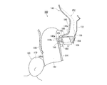
- the cushion part 102 is a part that inflates and deploys to protect the occupant in an emergency. As illustrated in FIG. 1A, the cushion portion 102 is wound around in a normal state and has a long and narrow roll-shaped storage configuration in the front and rear of the vehicle, and is attached to the upper portion of the vehicle body side wall (the roof side rail 104). 106. The roof side rail 104 is usually covered with a roof trim 108 (see FIG. 3). For this reason, the mounted cushion part 102 is invisible from the vehicle compartment.
- the storage form of the cushion part 102 can also be realized by folding.
- the upper part of the cushion part 102 is provided with, for example, a cylinder type (cylinder type) inflator 110 which is a gas generator.
- the cushion part 102 expand
- Inflators that are currently popular are types that are filled with a gas generating agent and burn it to generate gas, types that are filled with compressed gas and supply gas without generating heat, and There are types including both a gas generating agent and a compressed gas. Any type of inflator 110 can be used.
- a sensor (not shown) provided in the vehicle 106 senses an impact, resulting in this.
- a signal is transmitted to the inflator 110.
- the inflator 110 operates and gas is supplied to the cushion portion 102.
- the cushion portion 102 is directed downward along the side wall of the passenger compartment (such as the side window 112 in FIG. 1A) as illustrated in FIG. 1B. Inflate and deploy to protect passengers.
- the cushion portion 102 has a large shape that can be expanded along the side surface of the passenger compartment as a curtain airbag.
- the cushion portion 102 is formed in a bag shape by overlapping two base fabrics constituting the surface thereof, sewing and bonding, or spinning using OPW (One-Piece Woven).
- the expansion region of the cushion portion 102 is partitioned into a plurality of small rooms (chambers) in consideration of the position where the occupant can come into contact.
- chambers 116 and 118 are provided on the front side of the vehicle for the purpose of receiving the occupant of the front seat 114.
- a chamber 122 and the like are provided on the side of the rear seat 120 on the rear side of the vehicle.
- a plurality of attachment tabs 126 as attachment portions to the vehicle 106 are provided on the upper edge 124 of the cushion portion 102.
- the attachment tab 126 has a belt shape and is attached to the roof side rail 104 using a bolt or the like.
- a string-like strap 128 is provided at the front end of the cushion portion 102.
- the strap 128 is a member that connects the cushion portion 102 to the front pillar 130, suppresses the swinging of the cushion portion 102 during expansion and deployment, stabilizes the deployment behavior, and gives the cushion portion 102 tension in the vehicle longitudinal direction. .
- the airbag 100 includes a cover member 140 attached in the vicinity of the center pillar 132 (see FIG. 3) in the cushion portion 102.
- the cover member 140 is fixed to the roof side rail 104 at the top of the center pillar 132 using a bolt (not shown) inserted through the holes 142a and 142b (see FIG. 2).
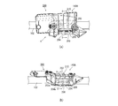
- FIG. 2 is an enlarged view illustrating the vicinity of the cover member 140 of FIG.
- FIG. 2A is a view of the cover member 140 holding the cushion portion 102 in the storage form as seen from the vehicle outer side in the vehicle width direction.
- FIG. 2B is a view as seen from an arrow A in FIG.
- FIG. 3 is a cross-sectional view of the cover member 140 and the cushion portion 102 of FIG. 2, and illustrates the roof trim 108, the center pillar 132, and the pillar garnish 144.
- FIG. 3A is a cross-sectional view taken along the line BB in FIG.
- FIG. 3B is a cross-sectional view illustrating a state in which the cushion portion 102 of FIG.
- the cover member 140 is made of resin, and has a long shape along the storage-type cushion portion 102 as illustrated in FIGS. 2A and 2B, and the storage-type cushion portion 140 102 covers, for example, the vehicle body side wall (the vehicle outer side) and the vehicle lower side. Moreover, the vehicle inner side of the cushion part 102 is covered with the roof trim 108 so that it may illustrate in Fig.3 (a).
- a pillar garnish 144 is disposed below the roof trim 108.
- the pillar garnish 144 is an interior material that covers the inside of the vehicle body side wall, and an upper end 144a of the pillar garnish 144 is in contact with the lower end 108a of the roof trim 108 from the inside of the vehicle.
- the cover member 140 includes an outer wall portion 146, a lower wall portion 148, a first vertical wall portion 150, and a rib 152, as illustrated in FIG.
- the outer side wall part 146 is located on the vehicle outer side of the cushion part 102 in the storage form, and extends in the vehicle vertical direction.
- the lower wall portion 148 extends from the vicinity of the lower end 146a of the outer wall portion 146 in an inclined manner toward the lower inside of the vehicle, and is positioned below the cushion portion 102.
- the first vertical wall portion 150 extends downward from the vicinity of the end portion 148a on the vehicle inner side of the lower wall portion 148.
- the first vertical wall portion 150 faces the pillar garnish 144 on the outside of the pillar garnish 144 with the lower end 108a of the roof trim 108 interposed therebetween.
- the ribs 152 are opposite to the outer wall portion 146 and the lower wall portion 148 on the opposite side where the stored cushion portion 102 is installed, that is, on the vehicle outer side of the outer wall portion 146 and the vehicle lower side of the lower wall portion 148. Is provided. Further, the cover member 140 has a gap portion 154 between the first vertical wall portion 150 and the rib 152 below the lower wall portion 148.
- the gap portion 154 is a predetermined region extending from the first vertical wall portion 150 to the vehicle outer side, and is located between the first wall portion 150 and the rib 152 and is a region where the rib 152 is not formed. Or the space
- the rib 152 is erected from the vehicle outer side of the gap portion 154, which is a predetermined region extending from the first vertical wall portion 150 to the vehicle outer side, on the vehicle lower side of the lower wall portion 148, from the vehicle outer side of the outer wall portion 146. Yes. That is, as illustrated in FIG. 3A, the rib 152 has a first dimension L ⁇ b> 1 indicating the length in the vehicle width direction from the first vertical wall 150 to the outside of the vehicle below the lower wall 148.
- the gap 154 is not formed.
- the rib 152 includes a lower region 156 located on the vehicle outer side of the gap portion 154. Furthermore, at least a part 158 of the rib 152 that is erected on the vehicle outer side from the outer wall portion 146 is in contact with the body panel (the side wall of the vehicle body).
- the cover member 140 includes a second vertical wall portion 160 and a partition wall 164.
- the second vertical wall portion 160 extends downward from the lower side wall portion 148 and is formed at a position separating the gap portion 154 from the first vertical wall portion 150.
- the second vertical wall portion 160 is in contact with the lower region 156 on the inner side of the lower region 156, thereby defining the outer side of the gap portion 154. That is, the lower region 156 is located on the vehicle exterior side of the gap portion 154 and the second vertical wall portion 160.
- the partition wall 164 extends from the base 166 of the second vertical wall portion 160 toward the vehicle outer side in the vehicle width direction, and further extends downward to partition the lower region 156 from the rib 152.
- the first dimension L1 is the length in the vehicle width direction of the gap portion 154, that is, the length in the vehicle width direction of the interval between the first vertical wall portion 150 and the second vertical wall portion 160. As illustrated in FIG. 3A, in the cover member 140, the first dimension L1 is smaller than the second dimension L2.
- the cover member 140 not only holds the cushion portion 102 in the storage form in a normal state, but also has a role to enable the cushion portion 102 to smoothly expand and deploy in an emergency.
- the cushion portion 102 inflates and expands in the passenger compartment space over the upper end 144a of the pillar garnish 144 while pushing the roof trim 108 away.
- the lower wall portion 148 of the cover member 140 receives a force from the cushion portion 102 that expands and deploys.
- the lower wall portion 148 is deformed by receiving a force from the cushion portion 102, the cushion portion 102 is caught, for example, between the center pillar 132 and the pillar garnish 144 (see FIG. 6B). There is a risk of deployment in directions other than the intended direction. Therefore, the lower side wall portion 148 of the cover member 140 is required to have rigidity in order to suppress deformation of the cushion portion 102 during expansion and deployment.
- the rib 152 is formed on the opposite side of the cover member 140 where the cushioned portion 102 is placed with respect to the outer wall portion 146 and the lower wall portion 148.
- a rib 152 including a lower region 156 is formed on the lower side wall portion 148.
- FIG. 4 is a diagram illustrating a state in which the head 170 of the occupant 168 collides with the cushion portion 102 after inflated and deployed from the state of FIG.
- the impact is transmitted to the pillar garnish 144 via the cushion portion 102.
- the pillar garnish 144 subjected to the impact is deformed to the outside of the vehicle and presses the lower side wall portion 148 of the cover member 140.
- the cover member 140 can avoid the poor deployment of the cushion portion 102 only by securing the rigidity of the lower side wall portion 148, but cannot absorb the impact when the head 170 of the occupant 168 collides, and occupant protection performance. Will be damaged.
- the rib 152 is not formed from the first vertical wall portion 150 to a predetermined region outside the vehicle, and the gap is formed between the first vertical wall portion 150 and the lower region 156 of the rib 152.
- a configuration forming part 154 was adopted.
- the first vertical wall portion 150 is first pressed against the pillar garnish 144.
- the first vertical wall portion 150 can be deformed to the vehicle outer side using the gap portion 154 until it abuts on the second vertical wall portion 160 in contact with the lower region 156 on the vehicle inner side of the lower region 156.
- the first vertical wall 150 can be deformed by the following modifications, as illustrated by the phantom line in FIG. 3B and the solid line in FIG. That is, the range from the root 166 of the second vertical wall portion 160 to the end portion 148a on the vehicle inner side of the lower wall portion 148 is made possible by displacing counterclockwise from the root 166 toward the vehicle outer side.
- the first vertical wall portion 150 of the lower wall portion 148 can absorb the impact by being deformed to the vehicle outer side when the head 170 of the occupant 168 collides with the cushion portion 102. For this reason, the head 170 of the occupant 168 does not receive a large reaction force, and the occupant protection performance is not impaired. That is, the cover member 140 enables the first vertical wall portion 150 to be deformed to the vehicle outer side while ensuring the rigidity of the lower wall portion 148.
- FIG. 5 is an enlarged view illustrating the vicinity of the cover member 140A of the airbag 200 of the comparative example.
- FIG. 5A is a view of the cover member 140A holding the cushion portion 102 in the storage form as viewed from the vehicle outer side in the vehicle width direction.
- FIG.5 (b) is a C arrow directional view of Fig.5 (a).
- 6 is a cross-sectional view of the cover member 140A and the cushion portion 102 of FIG.
- FIG. 6A is a DD cross-sectional view of FIG.
- FIG. 6B is a cross-sectional view illustrating a state where the cushion portion 102 of FIG. 6A is inflated and deployed in an emergency.
- the airbag 200 of the comparative example includes an outer wall portion 202 positioned on the vehicle outer side of the cushion portion 102 in a stored state, and a lower side wall portion 204 positioned on the lower side of the cushion portion 102. And a vertical wall portion 206 and a wall portion 208.
- the airbag 200 is different from the airbag 100 in that a rib 210 is erected on the vehicle outer side of the outer wall portion 202, but no rib is formed on the vehicle lower side of the lower wall portion 204.
- the lower wall portion 204 extends from the lower end 202a of the outer wall portion 202 in an inclined manner downward on the vehicle inner side.
- the vertical wall portion 206 extends downward from an end portion 204 a on the vehicle inner side of the lower wall portion 204.
- the vertical wall portion 206 faces the pillar garnish 144 on the outside of the pillar garnish 144 with the lower end 108a of the roof trim 108 interposed therebetween.
- the wall 208 divides the outer wall 202 and the lower wall 204 and extends from the lower end 202a of the outer wall 202 toward the vehicle exterior.
- the end 208 a of the wall 208 on the vehicle exterior side is in contact with the center pillar 132 together with the rib 210.
- the airbag 200 it is possible to prevent the outer wall portion 202 of the cover member 140A from being deformed to the vehicle outer side when the cushion portion 102 is inflated and deployed.
- the lower side wall portion 204 of the cover member 140A has no rib formed on the lower side of the vehicle, and thus cannot secure rigidity.
- the lower wall portion 204 is a vertical wall starting from the lower end 202a of the outer wall portion 202 as illustrated by the phantom line and the arrow E in FIG. Together with the portion 206, it is displaced counterclockwise toward the vehicle exterior.
- the cover member 140A when the lower wall portion 204 and the vertical wall portion 206 receive a force from the cushion portion 102 that expands and deploys in an emergency, the cover member 140A is deformed as indicated by a solid line in the drawing. To do. For this reason, for example, a gap 212 is generated between the center pillar 132 and the pillar garnish 144, more specifically between the vertical wall portion 206 and the pillar garnish 144.
- a part 102A of the cushion portion 102 may be caught in the gap 212 at the time of inflation and deployment, and the deployment behavior may be hindered and deployed in a direction other than the target direction. is there.
- the first vertical wall portion 150 can be deformed to the vehicle outer side while the rigidity of the lower wall portion 148 of the cover member 140 is ensured.
- the deployment behavior of the portion 102 is not hindered, and further, the passenger protection performance can be maintained.
- the lower wall portion 148 of the cover member 140 is deformed to the vehicle exterior until the first vertical wall portion 150 comes into contact with the second vertical wall portion 160 and is not further deformed, so that rigidity can be ensured. Since the first dimension L1 that is the length of the gap 154 in the vehicle width direction is smaller than the second dimension L2 that is the length of the lower area 156 in the vehicle width direction, the lower area 156 is wider than the gap 154 in the vehicle width. It is long in the direction. For this reason, the cover member 140 can ensure the rigidity of the lower wall portion 148 even if the gap portion 154 is formed.
- a part 158 of the rib 152 is in contact with the body panel. For this reason, in the cover member 140, the outer wall portion 146 is hardly deformed to the vehicle outer side when the cushion portion 102 is inflated and deployed, and the deformation of the lower wall portion 148 continuous with the outer wall portion 146 is further suppressed.
- the vehicle lower side of the lower wall portion 148 is reinforced by the partition wall 164 in addition to the second vertical wall portion 160 and the lower region 156. For this reason, in the cover member 140, the lower side wall part 148 becomes more difficult to deform when the cushion part 102 is inflated and deployed, and rigidity can be ensured even if the gap part 154 is formed.
- the present invention includes a cushion part that inflates and expands along a side part in a vehicle compartment for the purpose of protecting an occupant at the time of a side collision or rollover (rollover) of a vehicle, and a cover member attached to the cushion part. It can be used for a curtain airbag device.
Landscapes
- Engineering & Computer Science (AREA)
- Mechanical Engineering (AREA)
- Air Bags (AREA)
Abstract
Le problème décrit par la présente invention est de pourvoir à un système de rideau gonflable qui non seulement n'entrave pas l'action de déploiement lorsqu'une partie coussin est déployée de manière extensible, mais qui puisse également maintenir des performances protectrices d'un occupant lorsque la tête d'un occupant fait l'objet d'une collision. La solution selon l'invention porte sur un système de rideau gonflable (100) qui est pourvu d'une partie coussin (102) installée dans une partie supérieure d'une paroi latérale de carrosserie et stockée dans une forme longue et mince, et d'un élément de recouvrement (140) fixé à la partie coussin, l'élément de recouvrement étant pourvu : d'une partie paroi latérale externe (146) positionnée sur le côté externe de véhicule de la partie coussin stockée ; d'une partie paroi latérale inférieure (148) inclinée vers le bas en direction du côté interne de véhicule à partir du voisinage de l'extrémité inférieure de la partie paroi latérale externe, la partie paroi latérale inférieure étant positionnée sur un côté au-dessous de la partie coussin ; d'une première partie paroi verticale (150) s'étendant vers le bas depuis le voisinage de l'extrémité latérale interne de véhicule de la partie paroi latérale inférieure et faisant face à une garniture de montant (144) destinée à recouvrir le côté interne de véhicule de la paroi latérale de carrosserie, la première partie paroi verticale faisant face à la garniture de montant à partir du côté externe de véhicule de celle-ci ; et d'une nervure (152) prévue sur le côté de la partie paroi latérale externe et sur la partie paroi latérale inférieure en regard du côté au niveau duquel est installée la partie coussin, et l'élément de recouvrement comprenant une partie cavité (154) entre la première partie paroi verticale et la nervure au-dessous de la partie paroi latérale inférieure.
Priority Applications (1)
| Application Number | Priority Date | Filing Date | Title |
|---|---|---|---|
| JP2016510116A JP6185653B2 (ja) | 2014-03-28 | 2015-02-16 | カーテンエアバッグ装置 |
Applications Claiming Priority (2)
| Application Number | Priority Date | Filing Date | Title |
|---|---|---|---|
| JP2014070438 | 2014-03-28 | ||
| JP2014-070438 | 2014-03-28 |
Publications (1)
| Publication Number | Publication Date |
|---|---|
| WO2015146361A1 true WO2015146361A1 (fr) | 2015-10-01 |
Family
ID=54194899
Family Applications (1)
| Application Number | Title | Priority Date | Filing Date |
|---|---|---|---|
| PCT/JP2015/054117 Ceased WO2015146361A1 (fr) | 2014-03-28 | 2015-02-16 | Système de rideau gonflable |
Country Status (2)
| Country | Link |
|---|---|
| JP (1) | JP6185653B2 (fr) |
| WO (1) | WO2015146361A1 (fr) |
Cited By (3)
| Publication number | Priority date | Publication date | Assignee | Title |
|---|---|---|---|---|
| JP2018008633A (ja) * | 2016-07-14 | 2018-01-18 | 本田技研工業株式会社 | サイドカーテンエアバッグ装置 |
| EP3628542A1 (fr) * | 2018-09-27 | 2020-04-01 | Mazda Motor Corporation | Structure intérieure supérieure de véhicule |
| US11285900B1 (en) * | 2020-10-22 | 2022-03-29 | Ford Global Technologies, Llc | Airbag housing |
Citations (4)
| Publication number | Priority date | Publication date | Assignee | Title |
|---|---|---|---|---|
| JP2000168482A (ja) * | 1998-10-01 | 2000-06-20 | Toyota Motor Corp | 頭部保護エアバッグ袋体の配設構造 |
| JP2008230474A (ja) * | 2007-03-22 | 2008-10-02 | Toyota Motor Corp | カーテンエアバッグ装置 |
| US20080238049A1 (en) * | 2007-03-30 | 2008-10-02 | Nissan Technical Center North America, Inc. | Rear Pillar to Center Pillar Trim Joint Connection for Rear Seat Passenger Airbag Side Curtain Deployment |
| JP2014046841A (ja) * | 2012-08-31 | 2014-03-17 | Honda Motor Co Ltd | エアバッグ配設構造 |
-
2015
- 2015-02-16 JP JP2016510116A patent/JP6185653B2/ja active Active
- 2015-02-16 WO PCT/JP2015/054117 patent/WO2015146361A1/fr not_active Ceased
Patent Citations (4)
| Publication number | Priority date | Publication date | Assignee | Title |
|---|---|---|---|---|
| JP2000168482A (ja) * | 1998-10-01 | 2000-06-20 | Toyota Motor Corp | 頭部保護エアバッグ袋体の配設構造 |
| JP2008230474A (ja) * | 2007-03-22 | 2008-10-02 | Toyota Motor Corp | カーテンエアバッグ装置 |
| US20080238049A1 (en) * | 2007-03-30 | 2008-10-02 | Nissan Technical Center North America, Inc. | Rear Pillar to Center Pillar Trim Joint Connection for Rear Seat Passenger Airbag Side Curtain Deployment |
| JP2014046841A (ja) * | 2012-08-31 | 2014-03-17 | Honda Motor Co Ltd | エアバッグ配設構造 |
Cited By (8)
| Publication number | Priority date | Publication date | Assignee | Title |
|---|---|---|---|---|
| JP2018008633A (ja) * | 2016-07-14 | 2018-01-18 | 本田技研工業株式会社 | サイドカーテンエアバッグ装置 |
| CN107618474A (zh) * | 2016-07-14 | 2018-01-23 | 本田技研工业株式会社 | 侧帘式安全气囊装置 |
| US10300879B2 (en) | 2016-07-14 | 2019-05-28 | Honda Motor Co., Ltd. | Side curtain airbag system |
| EP3628542A1 (fr) * | 2018-09-27 | 2020-04-01 | Mazda Motor Corporation | Structure intérieure supérieure de véhicule |
| JP2020050166A (ja) * | 2018-09-27 | 2020-04-02 | マツダ株式会社 | 車両の上部内装構造 |
| CN110949306A (zh) * | 2018-09-27 | 2020-04-03 | 马自达汽车株式会社 | 车辆的上部内装构造 |
| JP7196506B2 (ja) | 2018-09-27 | 2022-12-27 | マツダ株式会社 | 車両の上部内装構造 |
| US11285900B1 (en) * | 2020-10-22 | 2022-03-29 | Ford Global Technologies, Llc | Airbag housing |
Also Published As
| Publication number | Publication date |
|---|---|
| JP6185653B2 (ja) | 2017-08-23 |
| JPWO2015146361A1 (ja) | 2017-04-13 |
Similar Documents
| Publication | Publication Date | Title |
|---|---|---|
| JP5595154B2 (ja) | カーテンエアバッグ | |
| JP6430652B2 (ja) | サイドエアバッグ装置 | |
| JP5606876B2 (ja) | カーテンエアバッグ | |
| JP6852154B2 (ja) | サイドエアバッグ装置 | |
| JP6214787B2 (ja) | カーテンエアバッグ装置 | |
| JP6810072B2 (ja) | サイドエアバッグ装置 | |
| WO2012144404A1 (fr) | Dispositif d'airbag rideau pour véhicule | |
| WO2018123427A1 (fr) | Dispositif de sac gonflable latéral | |
| JP2013086731A (ja) | エアバッグ装置 | |
| JP6185653B2 (ja) | カーテンエアバッグ装置 | |
| WO2013146076A1 (fr) | Système d'airbag de protection de la tête | |
| JP5972856B2 (ja) | カーテンエアバッグ装置 | |
| KR20130083264A (ko) | 조수석 에어백 모듈 | |
| JP5990156B2 (ja) | カーテンエアバッグ装置 | |
| JP5530747B2 (ja) | ガス整流装置 | |
| JP6009655B2 (ja) | エアバッグ装置 | |
| JP6072713B2 (ja) | カーテンエアバッグ装置およびカーテンエアバッグ用ブラケット装置 | |
| JP5947760B2 (ja) | カーテンエアバッグ装置 | |
| WO2019073826A1 (fr) | Dispositif de coussin de sécurité gonflable latéral | |
| JP6450544B2 (ja) | カーテンエアバッグ装置用取付構造およびカーテンエアバッグ装置 | |
| JP5551554B2 (ja) | カーテンエアバッグ装置 | |
| JP6379444B2 (ja) | エアバッグ装置 | |
| JP6084588B2 (ja) | カーテンエアバッグ装置 | |
| JP5948296B2 (ja) | カーテンエアバッグ装置 | |
| JP5846583B2 (ja) | カーテンエアバッグ |
Legal Events
| Date | Code | Title | Description |
|---|---|---|---|
| 121 | Ep: the epo has been informed by wipo that ep was designated in this application |
Ref document number: 15770124 Country of ref document: EP Kind code of ref document: A1 |
|
| ENP | Entry into the national phase |
Ref document number: 2016510116 Country of ref document: JP Kind code of ref document: A |
|
| NENP | Non-entry into the national phase | ||
| 122 | Ep: pct application non-entry in european phase |
Ref document number: 15770124 Country of ref document: EP Kind code of ref document: A1 |