WO2015146429A1 - Dispositif de comptage de particules - Google Patents
Dispositif de comptage de particules Download PDFInfo
- Publication number
- WO2015146429A1 WO2015146429A1 PCT/JP2015/055235 JP2015055235W WO2015146429A1 WO 2015146429 A1 WO2015146429 A1 WO 2015146429A1 JP 2015055235 W JP2015055235 W JP 2015055235W WO 2015146429 A1 WO2015146429 A1 WO 2015146429A1
- Authority
- WO
- WIPO (PCT)
- Prior art keywords
- light
- housing
- laser light
- detection means
- openings
- Prior art date
- Legal status (The legal status is an assumption and is not a legal conclusion. Google has not performed a legal analysis and makes no representation as to the accuracy of the status listed.)
- Ceased
Links
Images




Classifications
-
- G—PHYSICS
- G01—MEASURING; TESTING
- G01N—INVESTIGATING OR ANALYSING MATERIALS BY DETERMINING THEIR CHEMICAL OR PHYSICAL PROPERTIES
- G01N15/00—Investigating characteristics of particles; Investigating permeability, pore-volume or surface-area of porous materials
- G01N15/06—Investigating concentration of particle suspensions
-
- G—PHYSICS
- G01—MEASURING; TESTING
- G01N—INVESTIGATING OR ANALYSING MATERIALS BY DETERMINING THEIR CHEMICAL OR PHYSICAL PROPERTIES
- G01N15/00—Investigating characteristics of particles; Investigating permeability, pore-volume or surface-area of porous materials
- G01N15/10—Investigating individual particles
- G01N15/14—Optical investigation techniques, e.g. flow cytometry
- G01N15/1456—Optical investigation techniques, e.g. flow cytometry without spatial resolution of the texture or inner structure of the particle, e.g. processing of pulse signals
- G01N15/1459—Optical investigation techniques, e.g. flow cytometry without spatial resolution of the texture or inner structure of the particle, e.g. processing of pulse signals the analysis being performed on a sample stream
-
- G—PHYSICS
- G01—MEASURING; TESTING
- G01N—INVESTIGATING OR ANALYSING MATERIALS BY DETERMINING THEIR CHEMICAL OR PHYSICAL PROPERTIES
- G01N15/00—Investigating characteristics of particles; Investigating permeability, pore-volume or surface-area of porous materials
- G01N15/06—Investigating concentration of particle suspensions
- G01N15/075—Investigating concentration of particle suspensions by optical means
-
- G—PHYSICS
- G01—MEASURING; TESTING
- G01N—INVESTIGATING OR ANALYSING MATERIALS BY DETERMINING THEIR CHEMICAL OR PHYSICAL PROPERTIES
- G01N15/00—Investigating characteristics of particles; Investigating permeability, pore-volume or surface-area of porous materials
- G01N2015/0042—Investigating dispersion of solids
- G01N2015/0046—Investigating dispersion of solids in gas, e.g. smoke
-
- G—PHYSICS
- G01—MEASURING; TESTING
- G01N—INVESTIGATING OR ANALYSING MATERIALS BY DETERMINING THEIR CHEMICAL OR PHYSICAL PROPERTIES
- G01N15/00—Investigating characteristics of particles; Investigating permeability, pore-volume or surface-area of porous materials
- G01N15/10—Investigating individual particles
- G01N15/14—Optical investigation techniques, e.g. flow cytometry
- G01N2015/1486—Counting the particles
Definitions
- the present invention relates to a particle counter for measuring the number of particles floating in a specific place such as a chamber of a semiconductor manufacturing apparatus or an exhaust pipe.
- Particles such as dust generated in the semiconductor processing process and floating in the processing chamber cause the performance of the product to deteriorate. Therefore, in the semiconductor processing apparatus, in order to suppress the generation of particles, the inside of the processing chamber (chamber) is placed in a high vacuum state, and a particle counting device that measures particles floating in the processing chamber in real time is installed (for example, patents). Reference 1).
- FIG. 6 is a top view of the particle counter
- FIG. 7 is a cross-sectional view taken along line A′-A ′ of FIG. 6.
- the particle counting device is provided at a cylindrical casing 110, a pair of openings 111a and 111b formed on the peripheral surface of the casing 110 so as to face each other, and one end (base end) of the casing 110.
- the detectors 120a and 120b are included.
- the light detection units 120a and 120b include photodiodes 121a and 121b and cover glasses 122a and 122b for protecting the photodiodes 121a and 121b, respectively, and are arranged so as to face each other across the optical path of the laser light 130.
- a particle counter particles that enter the inside of the housing 110 from any one of the openings 111a and 111b emit scattered light when irradiated with the laser light 130 from the laser light source 112.
- the scattered light enters the light detection units 120a and 120b and is detected by the photodiodes 121a and 121b.
- the detection signal is sent to a data processing unit (not shown) including a computer or the like, and the data processing unit generates particles. Are counted.
- FIG. 8 shows an example of detection signals from the light detection units 120a and 120b.
- the particle counting device compares such a detection signal with a predetermined threshold voltage, determines that a portion where the detection signal exceeds the threshold voltage is a particle-derived signal peak, and counts particles.
- the present invention has been made in view of the above points.
- the object of the present invention is to reduce the noise appearing on the detection signal of scattered light in the particle counter to improve the S / N ratio. It is to enable detection.
- the particle counter according to the present invention which has been made to solve the above problems, a) a cylindrical housing; b) a pair of openings formed on the peripheral surface of the casing so as to face each other; c) a light source for irradiating the inside of the housing with laser light from the base end side to the front end side of the housing; d) A pair of light detectors arranged so as to sandwich the optical path of the laser light inside the housing, and detecting scattered light generated by irradiating the laser light to particles entering the housing from the opening.
- Means Have The pair of openings are formed on the base end side with respect to the region where the light detection means is arranged in the axial direction of the housing, and disturbance light incident from the openings directly enters the light detection means. It is characterized by reducing this.
- the particle counter of the present invention having the above-described configuration, the pair of openings are formed on the base end side (light source side) with respect to the region where the light detection means of the housing is disposed. For this reason, the disturbance light which directly enters the light detection means from the opening is reduced, and noise derived from the disturbance light appearing on the detection signal can be suppressed.
- the opening is provided on the base end side of the light detection means as in the present invention
- side scattered light that is, light scattered in a direction substantially orthogonal to the optical axis of the laser light
- the particle counter it is desirable to use a laser that emits laser light having a short wavelength (about 300 to 500 nm) as the laser light source.
- the particle counter According to the particle counter according to the present invention, it is possible to reduce noise appearing on the detection signal of scattered light from the particles, thereby making it possible to detect minute particles.
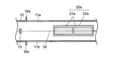
- FIG. 2 is a cross-sectional view taken along line AA in FIG. 1.
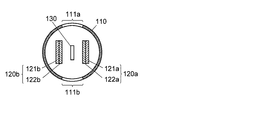
- FIG. 3 is a cross-sectional view taken along the line BB in FIG. 1.
- Sectional drawing which shows the modification of the particle counter concerning the said embodiment.
- Sectional drawing which shows another modification of the particle counting device which concerns on the said embodiment.
- FIG. 7 is a sectional view taken along arrow A′-A ′ in FIG. 6. The figure which shows an example of the detection signal by a particle counter.
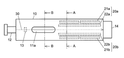
- FIGS. 1 is a top view of a particle counter according to an embodiment of the present invention
- FIG. 2 is a cross-sectional view taken along line AA in FIG. 1
- FIG. 3 is a cross-sectional view taken along line BB in FIG.
- Components that are the same as or correspond to those in FIGS. 6 and 7 described above are denoted by the same reference numerals in the last two digits as those given in FIGS. 6 and 7, and description thereof will be omitted as appropriate.
- the side where the laser light source 12 is provided in the axial direction of the housing 10 is the rear side (the base end side in the present invention), and the side where the beam stopper 14 is provided is the front (the front end side in the present invention). ).
- the particle counter according to the present embodiment is characterized in that a pair of openings 11a and 11b for allowing particles to pass through the housing 10 are provided behind the light detection units 20a and 20b. Thereby, the disturbance light which enters from the openings 11a and 11b and directly enters the light detection units 20a and 20b can be reduced, and noise derived from the disturbance light can be reduced.
- the openings 11a and 11b are arranged in the axial direction of the housing 10 so that ambient light that enters the housing 10 from the openings 11a and 11b does not directly enter the light detection units 20a and 20b. It is desirable to form it at a position sufficiently separated from the region where 20a and 20b are provided.
- Intensity I scat of the scattered light is inversely proportional to the fourth power of the wavelength ⁇ as shown by the following formula of Rayleigh scattering.
- I 0 intensity of irradiated light
- a radius of particle
- r distance from particle
- n refractive index of particle
- a laser light source 12 in the present embodiment that can emit laser light having a wavelength shorter than 500 nm (desirably about 300 to 500 nm, more preferably 400 to 500 nm).
- the intensity of the scattered light can be increased.
- the laser light with a short wavelength is irradiated, the scattered light from the particles is more strongly distributed forward (that is, the ratio of the forward scattered light to the entire scattered light is increased), and thus the light detection units 20a and 20b described above. It becomes possible to further improve the detection efficiency of the scattered light.
- the particle counter According to the particle counter according to the present embodiment, it is possible to improve the SN ratio of the detection signal and accurately count even minute particles.
- the region where the light detection units 20 a and 20 b are provided and the region where the openings 11 a and 11 b are formed do not overlap. These areas may be somewhat overlapped as long as the noise does not interfere with particle counting. In other words, it is preferable that the light detection unit can efficiently detect the forward scattered light and the opening is provided at a position where disturbance light is prevented from directly entering the light detection unit.
- the housing from the openings 11a and 11b of the disturbance light.
- a light blocking unit is provided on the optical path of the light. It is desirable to provide it.
- the light-shielding portion may include projecting portions 15 a and 15 b that are erected from the inner peripheral surface of the housing 10 toward the optical axis of the laser beam 30.
- the ambient light protrudes radially from the outer peripheral surface of the housing 10 at least at the rear end side of the periphery of the openings 11a and 11b so that the ambient light does not enter the housing 10 at a shallow angle. It is good also as a structure which provided the light-shielding part which consists of the protrusion parts 16a and 16b which do. 4 and 5 are sectional views showing a state in which the particle counter according to the present invention is cut along a plane that includes the optical axis of the laser beam 30 and is parallel to the light receiving surfaces of the photodiodes 21a and 21b.
- DESCRIPTION OF SYMBOLS 10, 110 ... Housing
Landscapes
- Chemical & Material Sciences (AREA)
- Dispersion Chemistry (AREA)
- Physics & Mathematics (AREA)
- Health & Medical Sciences (AREA)
- Life Sciences & Earth Sciences (AREA)
- Analytical Chemistry (AREA)
- Biochemistry (AREA)
- General Health & Medical Sciences (AREA)
- General Physics & Mathematics (AREA)
- Immunology (AREA)
- Pathology (AREA)
- Investigating Or Analysing Materials By Optical Means (AREA)
Abstract
L'invention concerne un dispositif de comptage de particules possédant : un boîtier cylindrique (10) ; une paire d'ouvertures (11a, 11b) formées de manière à se faire mutuellement face sur la surface circonférentielle du boîtier (10) ; une source lumineuse (12) qui diffuse une lumière laser (30) à l'intérieur du boîtier (10), à partir du côté d'extrémité de base du boîtier (10) vers le côté de pointe ; et une paire de moyens de détection de lumière (20a, 20b) agencés à l'intérieur du boîtier (10) de manière à interposer entre eux un trajet lumineux de la lumière laser (30) et qui détectent la lumière diffusée générée en résultat au fait que la lumière laser (30) est diffusée sur des particules qui sont entrées dans le boîtier (10) à partir des ouvertures (11a, 11b). L'ouverture (11a) est formée plus loin sur le côté d'extrémité de base dans la direction axiale du boîtier (10) qu'une zone dans laquelle les moyens de détection de lumière (20a, 20b) sont agencés.
Applications Claiming Priority (2)
| Application Number | Priority Date | Filing Date | Title |
|---|---|---|---|
| JP2014062068 | 2014-03-25 | ||
| JP2014-062068 | 2014-03-25 |
Publications (1)
| Publication Number | Publication Date |
|---|---|
| WO2015146429A1 true WO2015146429A1 (fr) | 2015-10-01 |
Family
ID=54194963
Family Applications (1)
| Application Number | Title | Priority Date | Filing Date |
|---|---|---|---|
| PCT/JP2015/055235 Ceased WO2015146429A1 (fr) | 2014-03-25 | 2015-02-24 | Dispositif de comptage de particules |
Country Status (1)
| Country | Link |
|---|---|
| WO (1) | WO2015146429A1 (fr) |
Cited By (1)
| Publication number | Priority date | Publication date | Assignee | Title |
|---|---|---|---|---|
| JP2020176915A (ja) * | 2019-04-18 | 2020-10-29 | 株式会社島津製作所 | パーティクル計数方法及びパーティクル計数装置 |
Citations (6)
| Publication number | Priority date | Publication date | Assignee | Title |
|---|---|---|---|---|
| JPS61272635A (ja) * | 1985-05-29 | 1986-12-02 | Nippon Kagaku Kogyo Kk | 微粒子計数装置 |
| JPH0283450U (fr) * | 1988-12-15 | 1990-06-28 | ||
| JPH0344539A (ja) * | 1989-07-13 | 1991-02-26 | Anelva Corp | 真空内ダスト監視装置 |
| JP2003098083A (ja) * | 2001-09-25 | 2003-04-03 | Matsushita Electric Works Ltd | 浮遊微粒子検知装置 |
| JP2006511822A (ja) * | 2002-12-18 | 2006-04-06 | ハンブルガー,ロベルト,エヌ. | 空中浮遊病原体検出システム及び方法 |
| JP2010534830A (ja) * | 2007-07-26 | 2010-11-11 | マルバーン インストゥルメンツ リミテッド | 光学的測定装置のための光線出力装置、光線出力方法、及び光散乱式測定器 |
-
2015
- 2015-02-24 WO PCT/JP2015/055235 patent/WO2015146429A1/fr not_active Ceased
Patent Citations (6)
| Publication number | Priority date | Publication date | Assignee | Title |
|---|---|---|---|---|
| JPS61272635A (ja) * | 1985-05-29 | 1986-12-02 | Nippon Kagaku Kogyo Kk | 微粒子計数装置 |
| JPH0283450U (fr) * | 1988-12-15 | 1990-06-28 | ||
| JPH0344539A (ja) * | 1989-07-13 | 1991-02-26 | Anelva Corp | 真空内ダスト監視装置 |
| JP2003098083A (ja) * | 2001-09-25 | 2003-04-03 | Matsushita Electric Works Ltd | 浮遊微粒子検知装置 |
| JP2006511822A (ja) * | 2002-12-18 | 2006-04-06 | ハンブルガー,ロベルト,エヌ. | 空中浮遊病原体検出システム及び方法 |
| JP2010534830A (ja) * | 2007-07-26 | 2010-11-11 | マルバーン インストゥルメンツ リミテッド | 光学的測定装置のための光線出力装置、光線出力方法、及び光散乱式測定器 |
Cited By (2)
| Publication number | Priority date | Publication date | Assignee | Title |
|---|---|---|---|---|
| JP2020176915A (ja) * | 2019-04-18 | 2020-10-29 | 株式会社島津製作所 | パーティクル計数方法及びパーティクル計数装置 |
| JP7115406B2 (ja) | 2019-04-18 | 2022-08-09 | 株式会社島津製作所 | パーティクル計数方法及びパーティクル計数装置 |
Similar Documents
| Publication | Publication Date | Title |
|---|---|---|
| US10670522B2 (en) | Micro object detection apparatus | |
| US9857287B2 (en) | Particulate sensor device | |
| KR101529127B1 (ko) | 광전식 연기 감지기 | |
| US20110255086A1 (en) | Optical sample detection system and sample analysis device | |
| JP5671873B2 (ja) | レーザ溶接モニタリング装置 | |
| JP2016540203A5 (ja) | 粒子特性評価装置 | |
| KR101574435B1 (ko) | 미세먼지 및 미생물 검출 장치 | |
| JP2011242397A (ja) | クロマティック共焦点センサ光学ペン | |
| JP2015200745A5 (fr) | ||
| KR101919103B1 (ko) | 반사경을 구비하지 않는 광학식 미생물 검출 장치 | |
| KR20160060845A (ko) | 광학식 센서를 위한 광학계 및 이를 포함하는 센서 | |
| KR101513542B1 (ko) | 광학계 | |
| JP7507384B2 (ja) | エアロゾル計測装置及びエアロゾル計測方法 | |
| KR20160114445A (ko) | 라이다 시스템 | |
| US8472021B2 (en) | Particle detector | |
| JP6129014B2 (ja) | 蛍光検出装置および蛍光検出方法 | |
| JP2004219131A (ja) | オイルミスト検出装置 | |
| JPS6335395Y2 (fr) | ||
| JP6330900B2 (ja) | 分光測定装置及び積分球 | |
| JP2015191462A (ja) | 煙感知器 | |
| KR101855554B1 (ko) | 광학식 센서를 위한 광학계 및 이를 포함하는 포토 센서 | |
| JP2015191466A (ja) | 煙感知器 | |
| JPH07146115A (ja) | 光センサ | |
| JPH05240770A (ja) | 粒子計数装置 | |
| JP2010096716A (ja) | 赤外線カメラ |
Legal Events
| Date | Code | Title | Description |
|---|---|---|---|
| 121 | Ep: the epo has been informed by wipo that ep was designated in this application |
Ref document number: 15769304 Country of ref document: EP Kind code of ref document: A1 |
|
| NENP | Non-entry into the national phase |
Ref country code: DE |
|
| 122 | Ep: pct application non-entry in european phase |
Ref document number: 15769304 Country of ref document: EP Kind code of ref document: A1 |
|
| NENP | Non-entry into the national phase |
Ref country code: JP |