WO2015146807A1 - Procédé pour la fabrication de film barrière aux gaz - Google Patents
Procédé pour la fabrication de film barrière aux gaz Download PDFInfo
- Publication number
- WO2015146807A1 WO2015146807A1 PCT/JP2015/058362 JP2015058362W WO2015146807A1 WO 2015146807 A1 WO2015146807 A1 WO 2015146807A1 JP 2015058362 W JP2015058362 W JP 2015058362W WO 2015146807 A1 WO2015146807 A1 WO 2015146807A1
- Authority
- WO
- WIPO (PCT)
- Prior art keywords
- gas barrier
- gas
- film
- barrier layer
- roller
- Prior art date
- Legal status (The legal status is an assumption and is not a legal conclusion. Google has not performed a legal analysis and makes no representation as to the accuracy of the status listed.)
- Ceased
Links
Images
Classifications
-
- C—CHEMISTRY; METALLURGY
- C23—COATING METALLIC MATERIAL; COATING MATERIAL WITH METALLIC MATERIAL; CHEMICAL SURFACE TREATMENT; DIFFUSION TREATMENT OF METALLIC MATERIAL; COATING BY VACUUM EVAPORATION, BY SPUTTERING, BY ION IMPLANTATION OR BY CHEMICAL VAPOUR DEPOSITION, IN GENERAL; INHIBITING CORROSION OF METALLIC MATERIAL OR INCRUSTATION IN GENERAL
- C23C—COATING METALLIC MATERIAL; COATING MATERIAL WITH METALLIC MATERIAL; SURFACE TREATMENT OF METALLIC MATERIAL BY DIFFUSION INTO THE SURFACE, BY CHEMICAL CONVERSION OR SUBSTITUTION; COATING BY VACUUM EVAPORATION, BY SPUTTERING, BY ION IMPLANTATION OR BY CHEMICAL VAPOUR DEPOSITION, IN GENERAL
- C23C16/00—Chemical coating by decomposition of gaseous compounds, without leaving reaction products of surface material in the coating, i.e. chemical vapour deposition [CVD] processes
- C23C16/44—Chemical coating by decomposition of gaseous compounds, without leaving reaction products of surface material in the coating, i.e. chemical vapour deposition [CVD] processes characterised by the method of coating
- C23C16/54—Apparatus specially adapted for continuous coating
- C23C16/545—Apparatus specially adapted for continuous coating for coating elongated substrates
-
- C—CHEMISTRY; METALLURGY
- C23—COATING METALLIC MATERIAL; COATING MATERIAL WITH METALLIC MATERIAL; CHEMICAL SURFACE TREATMENT; DIFFUSION TREATMENT OF METALLIC MATERIAL; COATING BY VACUUM EVAPORATION, BY SPUTTERING, BY ION IMPLANTATION OR BY CHEMICAL VAPOUR DEPOSITION, IN GENERAL; INHIBITING CORROSION OF METALLIC MATERIAL OR INCRUSTATION IN GENERAL
- C23C—COATING METALLIC MATERIAL; COATING MATERIAL WITH METALLIC MATERIAL; SURFACE TREATMENT OF METALLIC MATERIAL BY DIFFUSION INTO THE SURFACE, BY CHEMICAL CONVERSION OR SUBSTITUTION; COATING BY VACUUM EVAPORATION, BY SPUTTERING, BY ION IMPLANTATION OR BY CHEMICAL VAPOUR DEPOSITION, IN GENERAL
- C23C16/00—Chemical coating by decomposition of gaseous compounds, without leaving reaction products of surface material in the coating, i.e. chemical vapour deposition [CVD] processes
- C23C16/22—Chemical coating by decomposition of gaseous compounds, without leaving reaction products of surface material in the coating, i.e. chemical vapour deposition [CVD] processes characterised by the deposition of inorganic material, other than metallic material
- C23C16/30—Deposition of compounds, mixtures or solid solutions, e.g. borides, carbides, nitrides
- C23C16/40—Oxides
- C23C16/401—Oxides containing silicon
- C23C16/402—Silicon dioxide
-
- C—CHEMISTRY; METALLURGY
- C23—COATING METALLIC MATERIAL; COATING MATERIAL WITH METALLIC MATERIAL; CHEMICAL SURFACE TREATMENT; DIFFUSION TREATMENT OF METALLIC MATERIAL; COATING BY VACUUM EVAPORATION, BY SPUTTERING, BY ION IMPLANTATION OR BY CHEMICAL VAPOUR DEPOSITION, IN GENERAL; INHIBITING CORROSION OF METALLIC MATERIAL OR INCRUSTATION IN GENERAL
- C23C—COATING METALLIC MATERIAL; COATING MATERIAL WITH METALLIC MATERIAL; SURFACE TREATMENT OF METALLIC MATERIAL BY DIFFUSION INTO THE SURFACE, BY CHEMICAL CONVERSION OR SUBSTITUTION; COATING BY VACUUM EVAPORATION, BY SPUTTERING, BY ION IMPLANTATION OR BY CHEMICAL VAPOUR DEPOSITION, IN GENERAL
- C23C16/00—Chemical coating by decomposition of gaseous compounds, without leaving reaction products of surface material in the coating, i.e. chemical vapour deposition [CVD] processes
- C23C16/44—Chemical coating by decomposition of gaseous compounds, without leaving reaction products of surface material in the coating, i.e. chemical vapour deposition [CVD] processes characterised by the method of coating
- C23C16/50—Chemical coating by decomposition of gaseous compounds, without leaving reaction products of surface material in the coating, i.e. chemical vapour deposition [CVD] processes characterised by the method of coating using electric discharges
Definitions
- the present invention relates to a method for producing a gas barrier film.
- a gas barrier film in which a thin film (gas barrier layer) containing a metal oxide such as aluminum oxide, magnesium oxide, or silicon oxide is formed on the surface of a plastic substrate or film is used for packaging articles in the fields of food, medicine, etc. It is used for.
- a gas barrier film By using the gas barrier film, it is possible to prevent alteration of the article due to gas such as water vapor or oxygen.
- a method for producing a gas barrier film for example, a CVD method (Chemical Vapor Deposition: chemical vapor deposition method, chemical vapor deposition method) is used.
- CVD method Chemical Vapor Deposition: chemical vapor deposition method, chemical vapor deposition method
- the gas barrier film described in International Publication No. 2012/046767 has a problem that the gas barrier layer varies in the in-plane direction and the gas barrier performance is insufficient.
- the present invention has been made in view of the above problems, and an object of the present invention is to provide a method for producing a gas barrier film capable of forming a gas barrier layer with improved gas barrier performance.
- the present inventors have accumulated earnest research. As a result, when the gas barrier layer is formed by plasma enhanced chemical vapor deposition, it is found that the above-mentioned problems can be solved by setting the temperature in the gas chamber included in the film forming chamber to a specific range, and the present invention is completed. I came to let you.
- the present invention provides a plasma discharge by supplying a film forming gas between the opposed roller electrodes while supplying power to the opposed roller electrode having a magnetic field generator in the film forming chamber of the plasma enhanced chemical vapor deposition apparatus.
- a method for producing a gas barrier film comprising: forming a gas barrier layer on a substrate, wherein the temperature in the gas chamber of the film formation chamber is 80 to 300 ° C. Is the method.
- 11 is a gas-barrier film
- 12 is a base material
- 13 is a manufacturing apparatus
- 14 is a delivery roller
- 15, 16, 16 ′, 17, 17 ′, and 18 are transport rollers
- 19 and 20 are film forming rollers
- 21 is a gas supply pipe
- 22 is a power source for generating plasma
- 23 and 24 is a magnetic field generator
- 25 is a take-up roller
- 26 is a gas barrier layer
- 27 and 29 are transfer system chambers
- 28 is a film forming chamber
- 30 is a connecting portion
- 31 is A gas chamber.
- the present invention performs plasma discharge by supplying a film forming gas between the opposed roller electrodes while supplying power to the opposed roller electrode having the magnetic field generator in the film forming chamber of the plasma chemical vapor deposition apparatus.
- a method for producing a gas barrier film comprising: forming a gas barrier layer on a substrate, wherein the temperature in the gas chamber provided in the film formation chamber is 80 to 300 ° C. is there.
- the gas barrier film described in International Publication No. 2012/046767 has a gas barrier layer in which the composition of carbon, silicon and oxygen changes continuously in the film thickness direction.
- a gas barrier film has a problem that the gas barrier performance is not sufficient. This is because in the manufacturing method described in Patent Document 1, the composition of the gas barrier layer is in-plane because the applied power from the power source at the time of plasma discharge is low and the temperature in the gas chamber of the film forming chamber is as low as 70 ° C. or less. This is thought to be because the water vapor permeability of the gas barrier layer varies in the in-plane direction.
- the present inventors have provided a film-forming gas between the opposed roller electrodes while supplying power to the opposed roller electrode having a magnetic field generator in the film-forming chamber of the plasma enhanced chemical vapor deposition apparatus.
- the gas barrier layer is formed on the substrate by supplying the plasma to form a gas barrier layer, it has been found that the problem can be solved by setting the temperature in the gas chamber of the deposition chamber to 80 to 300 ° C. Thereby, desorption of the oxidation source (for example, moisture) existing on the surface of the substrate or in the vicinity of the surface is promoted, and the gas barrier layer is easily formed uniformly on the substrate.
- the gas barrier layer according to the present invention can be formed by plasma enhanced chemical vapor deposition (plasma CVD, plasma-enhanced chemical vapor deposition (PECVD), hereinafter also simply referred to as “plasma CVD method”).
- plasma CVD plasma enhanced chemical vapor deposition
- PECVD plasma-enhanced chemical vapor deposition
- the gas barrier layer according to the present invention preferably has a discharge space between opposing roller electrodes having a magnetic field generator for applying a magnetic field using a raw material gas containing an organosilicon compound and oxygen gas (roll-to-roll method). It is formed by plasma enhanced chemical vapor deposition. As described above, the plasma chemical vapor deposition method is used, and the temperature in the gas chamber included in the deposition chamber is within the range of the present invention, whereby the variation in the in-plane direction of the composition of the gas barrier layer is reduced. Variation in the in-plane direction of the water vapor transmission rate of the gas barrier layer is reduced, and a gas barrier film having a gas barrier layer with improved gas barrier performance can be produced.
- the gas barrier layer is densified, and the effect of repairing damage under high temperature and high humidity conditions is easily exhibited.
- the base material includes a form in which the base material has been processed or has an intermediate layer on the base material) and discharge between a pair of film forming rollers to generate plasma. Is more preferable.
- the film forming gas used in such a plasma CVD method preferably contains an organic silicon compound and oxygen, and the oxygen content in the film forming gas is the total amount of the organic silicon compound in the film forming gas. It is preferable that the amount of oxygen be less than the theoretical oxygen amount required for complete oxidation.
- an apparatus that can be used when producing a gas barrier layer by such a plasma CVD method is not particularly limited, and includes at least a pair of film formation rollers and a plasma power source, and the pair of film formations. It is preferable that the apparatus has a configuration capable of discharging between rollers. For example, when the manufacturing apparatus shown in FIG. 1 is used, the apparatus is manufactured by a roll-to-roll method using a plasma CVD method. It is also possible.
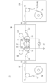
- FIG. 1 is a schematic view showing an example of a manufacturing apparatus (plasma chemical vapor deposition apparatus) that can be suitably used for manufacturing the gas barrier layer according to the present invention.
- a manufacturing apparatus plasma chemical vapor deposition apparatus
- the same or corresponding elements are denoted by the same reference numerals, and redundant description is omitted.
- the gas barrier layer may include only one layer or may include two or more layers.
- the materials of the plurality of gas barrier layers may be the same or different.
- the manufacturing apparatus 13 shown in FIG. 1 includes a delivery roller 14, transport rollers 15, 16, 17, 18, film formation rollers 19, 20, a gas supply pipe 21, a plasma generation power source 22, and a film formation roller 19. And 20 are provided with magnetic field generators 23 and 24 and winding rollers 25.
- a manufacturing apparatus at least the film forming rollers 19 and 20, the gas supply pipe 21, the plasma generating power source 22, the magnetic field generating apparatuses 23 and 24, and the gas chamber 31 are formed into a film (vacuum). It is disposed in the chamber 28. Further, in such a manufacturing apparatus 13, the vacuum chamber is connected to a vacuum pump (not shown), and the pressure in the vacuum chamber can be appropriately adjusted by the vacuum pump.
- a vacuum pump not shown
- the delivery roller 14 and the transport roller 15 are disposed in the transport system chamber 27, and the take-up roller 25 and the transport roller 18 are disposed in the transport system chamber 29.
- the transfer system chambers 27 and 29 and the film forming chamber 28 are connected via a connecting portion 30.
- the film forming chamber and the transfer system chamber may be physically separated by providing a vacuum gate valve in the connecting portion 30.
- the vacuum gate valve for example, only the inside of the film forming chamber can be a vacuum system and the inside of the transfer system chamber can be in the atmosphere. Further, by physically separating the film formation chamber and the transfer system chamber, contamination of the transfer system chamber with particles generated in the film formation chamber is suppressed.
- each film-forming roller has a power source for generating plasma so that the pair of film-forming rollers (film-forming roller 19 and film-forming roller 20) can function as a pair of counter electrodes. 22 is connected. Therefore, in such a manufacturing apparatus 13, it is possible to discharge to the space between the film forming roller 19 and the film forming roller 20 by supplying electric power from the plasma generating power source 22, thereby Plasma can be generated in the space between the film roller 19 and the film formation roller 20.
- the film formation roller 19 and the film formation roller 20 are used as electrodes, that is, as counter roller electrodes.
- the pair of film forming rollers (film forming rollers 19 and 20) be arranged so that their central axes are substantially parallel on the same plane.
- the film forming rate can be doubled as compared with a normal plasma CVD method in which no roller is used.
- the surface of the base material 12 here, the base material includes a form in which the base material is processed or has an intermediate layer on the base material
- gas barrier layer 26 It is possible to form a gas barrier layer 26 thereon, and deposit the gas barrier layer component on the surface of the substrate 12 on the film forming roller 19, and also on the surface of the substrate 12 on the film forming roller 20. Since the gas barrier layer component can be deposited, the gas barrier layer can be efficiently formed on the surface of the substrate 12.
- magnetic field generators 23 and 24 fixed so as not to rotate even when the film forming roller rotates are provided, respectively.
- the magnetic field generators 23 and 24 provided on the film forming roller 19 and the film forming roller 20 respectively are a magnetic field generator 23 provided on one film forming roller 19 and a magnetic field generator provided on the other film forming roller 20. It is preferable to arrange the magnetic poles so that the magnetic field lines do not cross between the magnetic field generators 24 and the magnetic field generators 23 and 24 form a substantially closed magnetic circuit.
- the magnetic field generators 23 and 24 provided on the film forming roller 19 and the film forming roller 20 respectively have racetrack-shaped magnetic poles that are long in the roller axis direction, and one magnetic field generating device 23 and the other magnetic field generating device. It is preferable to arrange the magnetic poles so that the magnetic poles facing 24 have the same polarity.
- the opposing space along the length direction of the roller shaft without straddling the magnetic field generator on the roller side where the magnetic lines of force of each of the magnetic field generators 23 and 24 are opposed.
- a racetrack-like magnetic field can be easily formed in the vicinity of the roller surface facing the (discharge region), and the plasma can be focused on the magnetic field, so that a wide base wound around the roller width direction can be obtained.
- the material 12 is excellent in that the gas barrier layer 26 that is a vapor deposition film can be efficiently formed.
- the tension on the base material in each roller may be the same, but the film may be formed by increasing only the tension in the film forming roller 19 or the film forming roller 20.
- the tension on the substrate in the film forming roller is improved, heat exchange is performed efficiently, film uniformity is improved, and thermal wrinkles are also suppressed.
- the film forming roller 19 and the film forming roller 20 known rollers can be appropriately used. As such film forming rollers 19 and 20, it is preferable to use ones having the same diameter from the viewpoint of forming a thin film more efficiently.
- the diameters of the film forming rollers 19 and 20 are preferably in the range of 100 to 1000 mm ⁇ , and particularly preferably in the range of 140 to 700 mm ⁇ , from the viewpoint of discharge conditions, chamber space, and the like. If the diameter of the film forming roller is 100 mm ⁇ or more, the plasma discharge space will not be reduced, so that the productivity will not be deteriorated, and it is possible to avoid applying the total amount of plasma discharge to the substrate 12 in a short time. It is preferable because damage to the material 12 can be reduced.
- each film-forming roller may be provided with a nip roll, and by providing the nip roll, the adhesion of the substrate to the roller is improved. For this reason, there is an advantage that heat exchange is efficiently performed between the substrate and the roller, film uniformity is improved, and heat wrinkles are suppressed.
- the base material 12 is disposed on a pair of film forming rollers (the film forming roller 19 and the film forming roller 20) so that the surfaces of the base material 12 face each other.
- the base material 12 By disposing the base material 12 in this way, when the plasma is generated by performing discharge in the facing space between the film forming roller 19 and the film forming roller 20, the base existing between the pair of film forming rollers is present.
- Each surface of the material 12 can be formed simultaneously. That is, according to such a manufacturing apparatus, the gas barrier layer component is deposited on the surface of the substrate 12 on the film forming roller 19 by the plasma CVD method, and further the gas barrier layer component is deposited on the film forming roller 20. Therefore, the gas barrier layer can be efficiently formed on the surface of the substrate 12.
- the temperature in the gas chamber 31 provided in the film forming chamber 28 is 80 to 300 ° C.
- the temperature is less than 80 ° C., desorption of the substrate surface or the oxidation source on the surface becomes insufficient.
- the temperature exceeds 300 ° C., the substrate is damaged by radiant heat.
- the temperature in the gas chamber 31 is preferably 100 to 250 ° C.
- the temperature in the gas chamber 31 is controlled by means of heat generated during plasma discharge (hereinafter also simply referred to as plasma heat); means for controlling by circulating a heat medium such as heat medium oil or water; ceramic It can be controlled by means for controlling the temperature, such as means for heating by a heater such as a heater; means for heating by radiant heat from an infrared lamp.
- the means for controlling these temperatures may be used alone or in combination of two or more.
- an electrode drum connected to a plasma generating power source 22 for discharging between the film forming roller 19 and the film forming roller 20 (in this embodiment)
- the power applied to the film forming rollers 19 and 20 (applied power) is preferably 25 to 160 W / cm per unit width of the substrate.
- the applied power per unit width of the substrate can be calculated by dividing the applied power of the power source by the substrate width.
- the temperature in the gas chamber 31 can be measured by thermography (measured through a window material that transmits infrared rays from outside the film forming chamber), thermocouple (directly measured film forming chamber), thermo label (directly measured film forming chamber), etc. It can be measured by using. Preferably, these measuring instruments are installed on the side surface of the gas chamber 31 for measurement. The temperature measurement result can be fed back to the above-described temperature control means, and the temperature in the gas chamber 31 can be controlled within a desired range.
- the width of the substrate 12 may be wider, narrower, or the same as the film forming roller width.
- the film formation roller is not exposed, so that the film formation roller can be prevented from being contaminated by particles, and the maintainability is improved and the performance is stabilized. is there.
- the base material width is narrower than the film forming roller width, there is an advantage that the effective width of the film to be formed is widened.
- the discharge width (film formation space) on the film formation roller and the position of the base material end can be appropriately adjusted by appropriately selecting the base material width.
- the substrate 12 may be heated before being transferred to the film forming chamber 28.
- the heating temperature is preferably equal to or higher than the glass transition temperature of the substrate.
- the temperature of the substrate 12 at the time of forming the gas barrier layer is not particularly limited, but is preferably ⁇ 20 to 60 ° C.
- the temperature of the substrate 12 depends on the temperature in the film forming chamber (discharge space) and the temperature of the film forming roller.
- the temperature of the film forming roller (opposing roller electrode) is preferably ⁇ 20 to 60 ° C. If it is this range, even if the temperature in a gas chamber is high conditions like this invention, the damage to the base material 12 can be suppressed and a higher quality gas-barrier film can be manufactured. it can.
- the film forming roller (counter roller electrode) may be appropriately heated and cooled by means such as a circulation of a heat medium or a refrigerant.
- the temperature of the substrate can be measured by thermography (measured through a window material that transmits infrared rays from outside the film forming chamber), a thermocouple, or a thermo label.
- the winding roller 25 is not particularly limited as long as the gas barrier film 11 having the gas barrier layer 26 formed on the substrate 12 can be wound, and a known roller may be used as appropriate. it can.
- a stepped roll may be used as the transport roller.
- the stepped roll is a transport roll in which only both ends of the roll are in contact with the substrate.
- a stepped roll described in FIG. 2 of JP-A-2009-256709 can be used.
- the delivery roller and the take-up roller may be a turret type.
- the turret may be multiaxial with two or more axes, and may have a structure in which only a part of the axes can be opened to the atmosphere.
- gas supply pipe 21 and the vacuum pump those capable of supplying or discharging the raw material gas at a predetermined speed can be appropriately used.
- the gas supply pipe 21 which is a gas supply means is preferably provided in one of the facing spaces (discharge region; film formation zone) between the film formation roller 19 and the film formation roller 20, and is a vacuum pump (vacuum exhaust means). (Not shown) is preferably provided on the other side of the facing space. In this way, by providing the gas supply pipe 21 as the gas supply means and the vacuum pump as the vacuum exhaust means, the film formation gas is efficiently supplied to the facing space between the film formation roller 19 and the film formation roller 20. It is excellent in that the film formation efficiency can be improved.
- the gas supply pipe 21 is on the center line between the film forming roller 19 and the film forming roller 20.
- the arrangement of the gas supply pipe 21 is not limited to such a form.
- the gas supply pipe 21 may be shifted to either one side from the center line between the film forming roller 19 and the film forming roller 20 (left-right direction). May be offset from the centerline).
- the gas supply pipe 21 is closer to one film formation roller and farther from the other film formation roller.
- the film composition formed on the film formation roller 19 and the film composition formed on the film formation roller 20 are different, and the gas supply pipe position may be appropriately shifted when it is desired to change the film quality.
- the gas supply pipe 21 may be appropriately separated from or closer to the film forming roller on the center line (the arrangement position may be moved on the center line in the vertical direction).
- the gas supply pipe 21 may be appropriately separated from or closer to the film forming roller on the center line (the arrangement position may be moved on the center line in the vertical direction).
- particles can be prevented from adhering to the gas supply pipe by moving the gas supply pipe 21 away from the center axis of the film forming roller and separating the gas supply pipe 21 from the discharge space.
- the film formation rate can be improved by approaching the discharge space on the central axis of the film formation roller.
- FIG. 1 there is one gas supply pipe 21, but there may be a plurality of gas supply pipes 21, and different supply gases may be discharged from each nozzle.
- a known power source for a plasma generating apparatus can be used as appropriate.
- a power source 22 for generating plasma supplies power to the film forming roller 19 and the film forming roller 20 connected thereto, and makes it possible to use them as a counter electrode for discharging.
- Such a plasma generation power source 22 can perform plasma CVD more efficiently, so that the polarity of the pair of film forming rollers can be alternately reversed (AC power source or the like). Is preferably used.
- power is supplied to both the film forming roller 19 and the film forming roller 20 by one power supply 22 (both film forming roller power supply), but is not limited to such a form.
- the film forming roller may be supplied with power (one-side film forming roller power supply) and the other film forming roller may be grounded.
- roller one-end power feeding from only one of the roller ends may be used, or roller both-end power feeding from both ends of the roller may be used. In the case of supplying a high frequency band, it is possible to supply both ends of the roller because uniform supply is possible.
- two-frequency feeding may be performed in which different frequencies are applied, and one film-forming roller and the other film-forming roller may be applied even when two different frequencies are applied to one film-forming roller.
- a different frequency may be applied.
- the plasma emission intensity in the discharge space is monitored from the outside, and if it is not the desired emission intensity, the distance between the magnetic fields (distance between the opposing rollers), the magnetic field intensity, and the applied power of the power source.
- a feedback circuit that adjusts the power supply frequency, the amount of supplied gas, and the like to obtain a desired plasma emission intensity may be provided. By having such a feedback circuit, film formation / production can be stabilized.
- magnetic field generators 23 and 24 known magnetic field generators can be used as appropriate.
- the method of controlling the maximum value of the atomic ratio of the oxygen atom content of the gas barrier layer is not particularly limited, but the ratio of the raw materials used (oxygen: supply ratio of HMDSO), power, pressure, etc. By controlling, the maximum value of the atomic ratio of the oxygen atom content can be controlled.
- the pressure (vacuum degree) in the film formation (vacuum) chamber can be appropriately adjusted according to the type of the raw material gas and the like, and is preferably about 0.5 Pa to 50 Pa, preferably 0.5 Pa to 10 Pa. Is more preferable.
- the transport speed (line speed) of the substrate 12 can be adjusted as appropriate according to the type of source gas, the pressure in the film forming chamber, etc., but is preferably in the range of 0.25 to 100 m / min. A range of 0.5 to 100 m / min is more preferable.
- a raw material gas, a reactive gas, a carrier gas, or a discharge gas can be used alone or in combination.
- the source gas in the deposition gas used for forming the gas barrier layer 26 can be appropriately selected and used according to the material of the gas barrier layer 26 to be formed.
- a source gas for example, an organic silicon compound containing silicon or an organic compound gas containing carbon can be used.
- organosilicon compounds examples include hexamethyldisiloxane (HMDSO), hexamethyldisilane (HMDS), 1,1,3,3-tetramethyldisiloxane, vinyltrimethylsilane, methyltrimethylsilane, hexamethyldisilane.
- HMDSO hexamethyldisiloxane
- HMDS hexamethyldisilane
- 1,1,3,3-tetramethyldisiloxane vinyltrimethylsilane
- methyltrimethylsilane hexamethyldisilane.
- Methylsilane dimethylsilane, trimethylsilane, diethylsilane, propylsilane, phenylsilane, vinyltriethoxysilane, vinyltrimethoxysilane, tetramethoxysilane (TMOS), tetraethoxysilane (TEOS), phenyltrimethoxysilane, methyltriethoxy
- TMOS tetramethoxysilane
- TEOS tetraethoxysilane
- phenyltrimethoxysilane methyltriethoxy
- Examples include silane and octamethylcyclotetrasiloxane.
- hexamethyldisiloxane and 1,1,3,3-tetramethyldisiloxane are preferable from the viewpoints of handling properties of the compound and gas barrier properties of the resulting gas barrier layer.
- organosilicon compounds can be used alone or in combination of two or more.
- organic compound gas containing carbon examples include methane, ethane, ethylene, and acetylene. Especially, since it can adjust to the film
- a reactive gas may be used in addition to the source gas.
- a gas that reacts with the raw material gas to become an inorganic compound such as an oxide can be appropriately selected and used.
- the reactive gas for example, oxygen and ozone can be used, and oxygen is preferably used from the viewpoint of simplicity.
- a reactive gas for forming a nitride may be used.
- nitrogen or ammonia can be used.
- a carrier gas may be used as necessary in order to supply the source gas into the film forming chamber (in the gas chamber).
- a discharge gas may be used as necessary in order to generate plasma discharge.
- carrier gas and discharge gas known ones can be used as appropriate, for example, rare gases such as helium, argon, neon and xenon; hydrogen; nitrogen can be used.
- paragraphs “0201” to “0204” of JP-A-2014-21801 can be appropriately referred to and employed.
- a film-forming gas (such as a raw material gas) is decomposed by plasma, and a gas barrier layer 26 is formed on the surface of the substrate 12 on the film-forming roller 19 and on the surface of the substrate 12 on the film-forming roller 20 by a plasma CVD method. Is done. At this time, a racetrack-shaped magnetic field is formed in the vicinity of the roller surface facing the facing space (discharge region) along the length direction of the roller axis of the film forming rollers 19 and 20, and the plasma is converged on the magnetic field.
- a film forming gas such as a raw material gas
- the composition of each atom is continuously changed in the film thickness direction.
- a layer in which the abundance ratio of carbon and oxygen in the film is not uniform is formed, and a portion having a large amount of carbon atoms is partially present, so that the entire layer has a flexible structure and is flexible. improves. That is, the gas barrier layer according to the present invention preferably satisfies the following conditions (i) to (iii).
- the gas barrier layer according to the present invention comprises (i) a distance (L) from the surface of the gas barrier layer in the thickness direction of the gas barrier layer, and a ratio of the amount of silicon atoms to the total amount of silicon atoms, oxygen atoms, and carbon atoms ( Silicon distribution curve showing the relationship between the atomic ratio of silicon and the oxygen distribution curve showing the relationship between the L and the ratio of the amount of oxygen atoms to the total amount of silicon atoms, oxygen atoms and carbon atoms (atomic ratio of oxygen) , And a carbon distribution curve showing the relationship between the L and the ratio of the amount of carbon atoms to the total amount of silicon atoms, oxygen atoms, and carbon atoms (the atomic ratio of carbon), 90% or more of the film thickness of the gas barrier layer In the region of (upper limit: 100%), (atomic ratio of oxygen), (atomic ratio of silicon), and (atomic ratio of carbon) are preferably increased in this order (atomic ratio is O> Si> C).
- the gas barrier property and flexibility of the resulting gas barrier film may be insufficient.
- the relationship between the above (atomic ratio of oxygen), (atomic ratio of silicon) and (atomic ratio of carbon) is at least 90% or more (upper limit: 100%) of the film thickness of the gas barrier layer. ) And more preferably at least 93% or more (upper limit: 100%).
- the term “at least 90% or more of the film thickness of the gas barrier layer” does not need to be continuous in the gas barrier layer.
- the carbon distribution curve has at least two extreme values.
- the gas barrier layer preferably has at least three extreme values in the carbon distribution curve, more preferably at least four extreme values, but may have five or more extreme values.
- the extreme value of the carbon distribution curve is 1 or less, the gas barrier property may be insufficient when the obtained gas barrier film is bent.
- the upper limit of the extreme value of the carbon distribution curve is not particularly limited, but is preferably 30 or less, more preferably 25 or less, for example. Since the number of extreme values is also caused by the film thickness of the gas barrier layer, it cannot be defined unconditionally.
- the distance from the surface of the gas barrier layer in the thickness direction of the gas barrier layer at one extreme value of the carbon distribution curve and the extreme value adjacent to the extreme value is preferably 200 nm or less, more preferably 100 nm or less, and particularly preferably 75 nm or less. preferable. If such a distance between extreme values is present, portions having a large carbon atom ratio (maximum value) are present in the gas barrier layer at an appropriate period, so that the gas barrier layer is imparted with an appropriate flexibility, Generation of cracks during bending can be more effectively suppressed / prevented.
- the “extreme value” means a maximum value or a minimum value of an atomic ratio of an element with respect to a distance (L) from the surface of the gas barrier layer in the thickness direction of the gas barrier layer.
- the “maximum value” is a point where the value of the atomic ratio of an element (oxygen, silicon or carbon) changes from increase to decrease when the distance from the surface of the gas barrier layer is changed.
- the value of the atomic ratio of the element at the position where the distance from the surface of the gas barrier layer in the thickness direction of the gas barrier layer from the point is further changed within the range of 4 to 20 nm than the value of the atomic ratio of the element at that point.
- the “minimum value” in this specification is a point in which the value of the atomic ratio of an element (oxygen, silicon, or carbon) changes from decrease to increase when the distance from the surface of the gas barrier layer is changed.
- the atomic ratio value of the element at a position where the distance from the point in the thickness direction of the gas barrier layer from the point in the thickness direction of the gas barrier layer is further changed by 4 to 20 nm is 3 at%. This is the point that increases.
- the atomic ratio value of the element when changing in the range of 4 to 20 nm, the atomic ratio value of the element only needs to increase by 3 at% or more in any range.
- the lower limit of the distance between the extreme values in the case of having at least three extreme values is particularly high because the smaller the distance between the extreme values, the higher the effect of suppressing / preventing crack generation when the gas barrier film is bent.
- the thickness is preferably 10 nm or more, and more preferably 30 nm or more.
- the gas barrier layer has (iii) an absolute value of a difference between the maximum value and the minimum value of the atomic ratio of carbon in the carbon distribution curve (hereinafter, also simply referred to as “C max ⁇ C min difference”) of 3 at% or more. It is preferable. When the absolute value is less than 3 at%, the gas barrier property is insufficient when the obtained gas barrier film is bent.
- the C max ⁇ C min difference is more preferably 5 at% or more, further preferably 7 at% or more, and particularly preferably 10 at% or more. By setting the C max ⁇ C min difference, the gas barrier property can be further improved.
- the “maximum value” is the atomic ratio of each element that is maximum in the distribution curve of each element, and is the highest value among the maximum values.
- the “minimum value” is the atomic ratio of each element that is the minimum in the distribution curve of each element, and is the lowest value among the minimum values.
- the upper limit of the C max -C min difference is not particularly limited, but it is preferably 50 at% or less in consideration of the effect of suppressing / preventing crack generation during bending of the gas barrier film, and is preferably 40 at% or less. It is more preferable that
- the oxygen distribution curve of the gas barrier layer preferably has at least one extreme value, more preferably has at least two extreme values, and more preferably has at least three extreme values.
- the oxygen distribution curve has at least one extreme value, the gas barrier property when the obtained gas barrier film is bent is further improved.
- the upper limit of the extreme value of the oxygen distribution curve is not particularly limited, but is preferably 20 or less, more preferably 10 or less, for example. Even in the number of extreme values of the oxygen distribution curve, there is a portion caused by the film thickness of the gas barrier layer, and it cannot be defined unconditionally.
- the difference in distance from the surface of the gas barrier layer in the film thickness direction of the gas barrier layer at one extreme value of the oxygen distribution curve and the extreme value adjacent to the extreme value are preferably 200 nm or less, more preferably 100 nm or less. With such a distance between extreme values, the occurrence of cracks during bending of the gas barrier film can be more effectively suppressed / prevented.
- the lower limit of the distance between the extreme values in the case of having at least three extreme values is not particularly limited, but considering the improvement effect of crack generation suppression / prevention when the gas barrier film is bent, the thermal expansion property, etc.
- the thickness is preferably 10 nm or more, and more preferably 30 nm or more.
- the silicon distribution curve, the oxygen distribution curve, the carbon distribution curve, and the oxygen carbon distribution curve are obtained by using X-ray photoelectron spectroscopy (XPS) measurement and rare gas ion sputtering such as argon in combination.
- XPS X-ray photoelectron spectroscopy
- rare gas ion sputtering such as argon in combination.
- XPS depth profile measurement in which surface composition analysis is sequentially performed while exposing the inside of the sample.
- a distribution curve obtained by such XPS depth profile measurement can be created, for example, with the vertical axis as the atomic ratio (unit: at%) of each element and the horizontal axis as the etching time (sputtering time).
- the etching time generally correlates with the distance (L) from the surface of the gas barrier layer in the film thickness direction of the gas barrier layer in the film thickness direction. Therefore, “Distance from the surface of the gas barrier layer in the thickness direction of the gas barrier layer” is the distance from the surface of the gas barrier layer calculated from the relationship between the etching rate and the etching time used in the XPS depth profile measurement. can do.
- the silicon distribution curve, oxygen distribution curve, carbon distribution curve, and oxygen carbon distribution curve were prepared under the following measurement conditions.
- Etching ion species Argon (Ar + ); Etching rate (converted to SiO 2 thermal oxide film): 0.05 nm / sec; Etching interval (SiO 2 equivalent value): 10 nm;
- X-ray photoelectron spectrometer Model name "VG Theta Probe", manufactured by Thermo Fisher Scientific; Irradiation X-ray: Single crystal spectroscopy AlK ⁇ X-ray spot and its size: 800 ⁇ 400 ⁇ m oval.
- each gas barrier layer has the above thickness.
- the thickness of the entire gas barrier layer in the case where the gas barrier layer is composed of two or more layers is not particularly limited, but the thickness (dry film thickness) of the entire gas barrier layer is preferably about 1000 to 2000 nm. With such a thickness, the gas barrier film can exhibit excellent gas barrier properties and the effect of suppressing / preventing cracking during bending.
- the gas barrier layer is substantially uniform in the film surface direction (direction parallel to the surface of the gas barrier layer) from the viewpoint of forming a gas barrier layer having a uniform and excellent gas barrier property over the entire film surface.
- the gas barrier layer is substantially uniform in the film surface direction means that the oxygen distribution curve, the carbon distribution curve, and the oxygen carbon are measured at any two measurement points on the film surface of the gas barrier layer by XPS depth profile measurement.
- the carbon distribution curve is substantially continuous.
- the carbon distribution curve is substantially continuous means that the carbon distribution curve does not include a portion where the atomic ratio of carbon changes discontinuously.
- the carbon distribution curve is calculated from the etching rate and the etching time. In the relationship between the distance (x, unit: nm) from the surface of the gas barrier layer in the film thickness direction of at least one of the gas barrier layers, and the atomic ratio of carbon (C, unit: at%), It means satisfying the condition represented by the following formula (1).
- the gas barrier layer that satisfies all the above conditions (i) to (iii) may include only one layer or two or more layers. Furthermore, when two or more such gas barrier layers are provided, the materials of the plurality of gas barrier layers may be the same or different.
- the silicon atomic ratio, the oxygen atomic ratio, and the carbon atomic ratio are in the region of 90% or more of the thickness of the gas barrier layer (i ),
- the atomic ratio of the silicon atom content to the total amount of silicon atoms, oxygen atoms, and carbon atoms in the gas barrier layer is preferably 20 to 45 at%, More preferably, it is 25 to 40 at%.
- the atomic ratio of the oxygen atom content to the total amount of silicon atoms, oxygen atoms, and carbon atoms in the gas barrier layer is preferably 45 to 75 at%, more preferably 50 to 70 at%.
- the atomic ratio of the carbon atom content to the total amount of silicon atoms, oxygen atoms, and carbon atoms in the gas barrier layer is preferably 1 to 25 at%, and more preferably 2 to 20 at%. .
- the substrate 12 passes through the point A of the film forming roller 19 and the point B of the film forming roller 20 in FIG. 1 in the silicon distribution curve, oxygen distribution curve, and carbon distribution curve. In this case, the maximum value of the carbon distribution curve and the minimum value of the oxygen distribution curve are formed.
- the substrate 12 passes through the points C1 and C2 of the film forming roller 19 and the points C3 and C4 of the film forming roller 20 in FIG. A local maximum of the oxygen distribution curve is formed. For this reason, five extreme values are usually generated in the carbon / oxygen distribution curve for the two film forming rollers.
- the distance between extreme values of the gas barrier layer (one extreme value of the carbon / oxygen distribution curve and the distance (L) from the surface of the gas barrier layer in the thickness direction of the gas barrier layer at the extreme value adjacent to the extreme value)
- the absolute value of the difference can be adjusted by the rotation speed of the film forming rollers 19 and 20 (the conveyance speed of the substrate).
- the substrate 12 is transported by the delivery roller 14 and the film formation roller 19, respectively, so that the surface of the substrate 12 is formed by a roll-to-roll continuous film formation process. Then, the gas barrier layer 26 is formed.
- the present embodiment is characterized in that the gas barrier layer is formed by a plasma CVD method using the plasma CVD apparatus (roll-to-roll method) having the counter roller electrode shown in FIG. .
- the gas barrier layer is formed by a plasma CVD method using the plasma CVD apparatus (roll-to-roll method) having the counter roller electrode shown in FIG. .
- Such a manufacturing apparatus is also excellent in that it can inexpensively and easily mass-produce gas barrier films that are required for durability against temperature changes used in solar cells and electronic components.
- the gas barrier film according to the present invention usually uses a plastic film as a substrate.
- the plastic film to be used is not particularly limited in material, thickness and the like as long as it can hold the gas barrier layer, and can be appropriately selected according to the purpose of use.
- Specific examples of the plastic film include polyester resin, methacrylic resin, methacrylic acid-maleic acid copolymer, polystyrene resin, transparent fluororesin, polyimide, fluorinated polyimide resin, polyamide resin, polyamideimide resin, and polyetherimide resin.
- Cellulose acylate resin Polyurethane resin, polyetheretherketone resin, polycarbonate resin, alicyclic polyolefin resin, polyarylate resin, polyethersulfone resin, polysulfone resin, cycloolefin copolymer, fluorene ring modified polycarbonate resin, alicyclic modification
- thermoplastic resins such as polycarbonate resin, fluorene ring-modified polyester resin, and acryloyl compound.
- the thickness of the plastic film used for the gas barrier film is not particularly limited because it is appropriately selected depending on the application, but is preferably 1 to 800 ⁇ m, more preferably 10 to 200 ⁇ m.
- These plastic films may have functional layers such as a clear hard coat layer, a transparent conductive layer, a smooth layer, and an easy adhesion layer.
- As the functional layer in addition to those described above, those described in paragraphs “0036” to “0038” of JP-A-2006-289627 can be preferably employed.
- the surface of the substrate may be subjected to various known treatments for improving adhesion, such as corona discharge treatment, flame treatment, oxidation treatment, plasma treatment, etc., and the above treatments are performed in combination as necessary. It may be.
- the following intermediate layer may be provided on the above-mentioned base material and gas barrier layer or surface as long as the effects of the present invention are not impaired.
- an anchor coat layer On the surface of the base material according to the present invention, an anchor coat layer may be formed as an easy adhesion layer for the purpose of improving adhesiveness (adhesion).
- an anchor coat layer As the constituent material and formation method of the anchor coat layer, the materials and methods disclosed in paragraphs “0229” to “0232” of JP2013-52561A are appropriately employed.
- the gas barrier film may have a smooth layer between the surface of the base material having the gas barrier layer, preferably between the base material and the gas barrier layer.
- the smooth layer is provided in order to flatten the rough surface of the base material on which protrusions and the like exist, or to fill the unevenness and pinholes generated in the gas barrier layer with the protrusions on the base material.
- the materials, methods, etc. disclosed in paragraphs “0233” to “0248” of JP2013-52561A are appropriately employed as the constituent material, forming method, surface roughness, film thickness, etc. of the smooth layer.
- the gas barrier film may further have a bleed-out preventing layer.
- the bleed-out prevention layer has a smooth layer for the purpose of suppressing the phenomenon of unreacted oligomers moving from the base material to the surface when the film having the smooth layer is heated and contaminating the contact surface.
- the bleed-out prevention layer may basically have the same configuration as the smooth layer as long as it has this function.
- the constituent material, forming method, film thickness and the like of the bleed-out prevention layer the materials, methods and the like disclosed in paragraphs “0249” to “0262” of JP2013-52561A are appropriately employed.
- the gas barrier film of the present invention as described above has excellent gas barrier properties, transparency, flexibility and the like.
- the gas barrier film of the present invention is a package such as an electronic device, a photoelectric conversion element (solar cell element), an organic electroluminescence (EL) element, a liquid crystal display element, a liquid crystal display element (LCD), electronic paper, a thin film transistor, It can be used for various applications such as a gas barrier film used for an electronic device having an electronic element body such as a touch panel and an electronic device using the same.
- the electronic element body is preferably an organic EL element or a solar battery.
- Example 1 Preparation of Sample 1
- base material A polyethylene terephthalate film with a clear hard coat layer (abbreviation: PET film, thickness: 125 ⁇ m, width: 1000 mm, manufactured by Kimoto Co., Ltd., trade name: GSABR) was used as a substrate.
- PET film thickness: 125 ⁇ m, width: 1000 mm, manufactured by Kimoto Co., Ltd., trade name: GSABR
- ⁇ Plasma CVD conditions Feed rate of source gas (hexamethyldisilazane): 1.5 sccm / cm (Sccm: Standard Cubic Centimeter per Minute) Supply amount of oxygen gas (O 2 ): 10 sccm / cm Temperature in the gas chamber: 80 ° C Degree of vacuum in the deposition chamber: 1.5 Pa Applied power per unit width of the substrate from the power source for plasma generation: 23 W / cm Frequency of power source for plasma generation: 80 kHz Substrate transport speed: 10 m / min Number of treatments: 6 times The inside of the gas chamber was further heated by heat medium circulation (heat medium: heat medium oil), and the temperature in the gas chamber was confirmed by a thermocouple provided on the side surface of the gas chamber.
- heat medium heat medium oil
- the temperature of the substrate was measured by thermography.
- Example 2 Production of sample 2
- the temperature in the gas chamber was heated to 100 ° C. by plasma heat and heat medium circulation, and the temperature of the heat medium circulating in the film forming roll was controlled to set the temperature of the substrate to 30 ° C.
- Sample 2 was produced in the same manner as Example 1 except for the above.
- Example 3 Production of sample 3
- Sample 3 was produced in the same manner as in Example 1 except that the applied power per unit width of the base material from the power source for generating plasma was 40 W / cm and that heating by heating medium circulation was not performed.
- the temperature in the gas chamber was 120 ° C. due to heat generated by the plasma discharge.
- Sample 4 was produced in the same manner as in Example 3 except that the applied power per unit width of the substrate from the power source for generating plasma was 57 W / cm. The temperature in the gas chamber was 150 ° C. due to heat generated by the plasma discharge.
- Example 5 Preparation of sample 5
- Sample 5 was produced in the same manner as in Example 3 except that the applied power per unit width of the base material from the power source for generating plasma was 73 W / cm.
- the temperature in the gas chamber was 200 ° C. due to heat generated by the plasma discharge.
- Example 6 Production of sample 6
- Sample 6 was produced in the same manner as in Example 3 except that the applied power per unit width of the base material from the power source for generating plasma was 90 W / cm.
- the temperature in the gas chamber was 250 ° C. due to heat generated by the plasma discharge.
- Example 7 Production of sample 7
- Sample 7 was produced in the same manner as in Example 1 except that the inside of the gas chamber was heated with plasma heat and a ceramic heater, and the temperature was set to 300 ° C.
- Example 8 Production of sample 8
- Sample 8 was produced in the same manner as in Example 3 except that the power applied from the power source for generating plasma was 100 W / cm and the gas chamber was cooled by heat medium circulation (heat medium: water). The temperature in the gas chamber was 150 ° C.
- Example 9 Production of sample 9
- the temperature in the gas chamber was heated to 100 ° C. by plasma heat and heat medium circulation, and the temperature of the heat medium circulating in the film forming roll was controlled to set the temperature of the substrate to 70 ° C.
- Sample 9 was produced in the same manner as Example 1 except for the above.
- Example 10 Production of sample 10
- the temperature in the gas chamber is heated to 100 ° C. by plasma heat and heat medium circulation, and the temperature of the heat medium circulating in the film forming roll is controlled to set the temperature of the substrate to ⁇ 30 ° C.
- a sample 10 was made in the same manner as in Example 1 except that.
- Sample 11 was produced in the same manner as in Example 1 except that the gas chamber was cooled by heat medium circulation (heat medium: water) and the temperature in the gas chamber was set to 60 ° C.
- heat medium water
- Sample 12 was produced in the same manner as in Example 1 except that the gas chamber was cooled by heat medium circulation (heat medium: water) and the temperature in the gas chamber was set to 40 ° C.
- heat medium water
- Sample 13 was produced in the same manner as in Example 1 except that the inside of the gas chamber was heated by plasma heat and a ceramic heater, and the temperature was 350 ° C.
- Sample 14 was produced in the same manner as in Example 1 except that heating by circulating the heat medium was not performed.
- the temperature in the gas chamber was 70 ° C. due to plasma heat.
- Sample 15 was produced in the same manner as in Example 1 except that the inside of the gas chamber was heated with plasma heat and a ceramic heater, and the temperature was 310 ° C.
- the atomic composition of the gas barrier layer was determined by creating a silicon distribution curve, an oxygen distribution curve, a carbon distribution curve, and an oxygen carbon distribution curve from the XPS depth profile determined under the following measurement conditions.
- the gas barrier films of Examples 1 to 10 were in the order of (atomic ratio of oxygen), (atomic ratio of silicon), and (atomic ratio of carbon) in the region of 90% or more of the film thickness of the gas barrier layer. It was confirmed that the ratio was large (atomic ratio: O> Si> C).
- Etching ion species Argon (Ar + ); Etching rate (converted to SiO 2 thermal oxide film): 0.05 nm / sec; Etching interval (SiO 2 equivalent value): 10 nm;
- X-ray photoelectron spectrometer Model name "VG Theta Probe", manufactured by Thermo Fisher Scientific; Irradiation X-ray: Single crystal spectroscopy AlK ⁇ X-ray spot and its size: 800 ⁇ 400 ⁇ m oval.
- a vacuum vapor deposition device vacuum vapor deposition device JEE-400, manufactured by JEOL Ltd.
- vacuum vapor deposition device JEE-400 manufactured by JEOL Ltd.
- the gas barrier film sample before the transparent conductive film is attached A portion other than the desired portion (20 mm ⁇ 20 mm) was masked and metal calcium was deposited. Thereafter, the mask was removed in a vacuum state, and aluminum was deposited from another metal deposition source on the calcium deposition surface. After aluminum sealing, the vacuum state is released, and the aluminum sealing side is quickly passed through a UV-curable resin (manufactured by Nagase ChemteX Corporation) to 0.2 mm thick quartz glass in a dry nitrogen gas atmosphere. And an evaluation cell was produced by irradiating with ultraviolet rays.
- a UV-curable resin manufactured by Nagase ChemteX Corporation
- the obtained sample with both sides sealed (evaluation cell) was stored at 85 ° C. and 85% RH under high temperature and high humidity for 100 hours, and corrosion of metallic calcium was carried out based on the method described in JP-A-2005-283561.
- the amount of moisture permeated into the cell was calculated from the amount.
- a sample obtained by depositing metallic calcium using a quartz glass plate having a thickness of 0.2 mm instead of the gas barrier film sample as a comparative sample was stored under the same high temperature and high humidity conditions of 85 ° C. and 85% RH, and it was confirmed that no corrosion of metallic calcium occurred even after 1000 hours.
- the average value of the amount of permeated water (WVTR) was calculated for 27 points of each gas barrier film sample measured as described above, and the average value was compared with the maximum value and evaluated according to the following criteria.
- Ratio of the average value of 27 points to the maximum value is less than 3 times
- ⁇ Ratio of the average value of 27 points to the maximum value is 3 times or more and less than 5 times
- ⁇ Ratio of the average value of 27 points to the maximum value 5 times or more and less than 10 times
- ⁇ The ratio of the average value of 27 points to the maximum value is 10 times or more.
- ⁇ Deformation of the base material is not observed. ⁇ : Substrate deformation is observed slightly. ⁇ : The base material is deformed.
- Table 1 below shows the production conditions and evaluation results of the examples and comparative examples.
- the gas barrier films obtained by the production methods of Examples 1 to 10 have a variation in water vapor transmission rate in the gas barrier layer as compared with the gas barrier films obtained by the production methods of the comparative examples. Has been found to have a low gas barrier layer. Therefore, it was found that the gas barrier films obtained by the production methods of Examples 1 to 10 were more improved in gas barrier performance than the gas barrier films of the comparative examples.
Landscapes
- Chemical & Material Sciences (AREA)
- Engineering & Computer Science (AREA)
- Mechanical Engineering (AREA)
- Chemical Kinetics & Catalysis (AREA)
- General Chemical & Material Sciences (AREA)
- Materials Engineering (AREA)
- Metallurgy (AREA)
- Organic Chemistry (AREA)
- Inorganic Chemistry (AREA)
- Physics & Mathematics (AREA)
- Plasma & Fusion (AREA)
- Chemical Vapour Deposition (AREA)
- Laminated Bodies (AREA)
Abstract
La présente invention concerne un procédé pour la fabrication d'un film barrière aux gaz, qui permet de former une couche barrière aux gaz présentant une meilleure efficacité de barrière aux gaz. Le procédé pour la fabrication d'un film barrière aux gaz selon la présente invention comprend une étape dans laquelle, alors que de l'énergie est apportée à des électrodes-rouleaux se faisant face comprenant un dispositif de production de champ magnétique à l'intérieur de la chambre de dépôt d'un dispositif de dépôt chimique en phase vapeur assisté par plasma, une injection de plasma est effectuée avec apport simultané d'un gaz de dépôt entre les électrodes-rouleaux se faisant face et une couche barrière aux gaz est déposée sur un matériau de base, la température de la chambre à gaz disposée dans la chambre de dépôt étant de 80 à 300° C.
Priority Applications (1)
| Application Number | Priority Date | Filing Date | Title |
|---|---|---|---|
| JP2016510289A JP6579098B2 (ja) | 2014-03-26 | 2015-03-19 | ガスバリア性フィルムの製造方法 |
Applications Claiming Priority (2)
| Application Number | Priority Date | Filing Date | Title |
|---|---|---|---|
| JP2014064633 | 2014-03-26 | ||
| JP2014-064633 | 2014-03-26 |
Publications (1)
| Publication Number | Publication Date |
|---|---|
| WO2015146807A1 true WO2015146807A1 (fr) | 2015-10-01 |
Family
ID=54195327
Family Applications (1)
| Application Number | Title | Priority Date | Filing Date |
|---|---|---|---|
| PCT/JP2015/058362 Ceased WO2015146807A1 (fr) | 2014-03-26 | 2015-03-19 | Procédé pour la fabrication de film barrière aux gaz |
Country Status (2)
| Country | Link |
|---|---|
| JP (1) | JP6579098B2 (fr) |
| WO (1) | WO2015146807A1 (fr) |
Citations (3)
| Publication number | Priority date | Publication date | Assignee | Title |
|---|---|---|---|---|
| JP2011162851A (ja) * | 2010-02-10 | 2011-08-25 | Fujifilm Corp | ガスバリアフィルムの製造方法 |
| JP2012097354A (ja) * | 2010-10-08 | 2012-05-24 | Sumitomo Chemical Co Ltd | 積層体の製造方法 |
| JP2013229608A (ja) * | 2012-04-26 | 2013-11-07 | Spts Technologies Ltd | 二酸化珪素フィルムを付着させる方法 |
Family Cites Families (3)
| Publication number | Priority date | Publication date | Assignee | Title |
|---|---|---|---|---|
| WO2012046767A1 (fr) * | 2010-10-08 | 2012-04-12 | 住友化学株式会社 | Film stratifié |
| CN104220249B (zh) * | 2012-03-27 | 2016-08-24 | 住友化学株式会社 | 层叠膜、有机电致发光装置、光电转换装置及液晶显示器 |
| JP2014000782A (ja) * | 2012-06-21 | 2014-01-09 | Sumitomo Chemical Co Ltd | 積層フィルム |
-
2015
- 2015-03-19 JP JP2016510289A patent/JP6579098B2/ja not_active Expired - Fee Related
- 2015-03-19 WO PCT/JP2015/058362 patent/WO2015146807A1/fr not_active Ceased
Patent Citations (3)
| Publication number | Priority date | Publication date | Assignee | Title |
|---|---|---|---|---|
| JP2011162851A (ja) * | 2010-02-10 | 2011-08-25 | Fujifilm Corp | ガスバリアフィルムの製造方法 |
| JP2012097354A (ja) * | 2010-10-08 | 2012-05-24 | Sumitomo Chemical Co Ltd | 積層体の製造方法 |
| JP2013229608A (ja) * | 2012-04-26 | 2013-11-07 | Spts Technologies Ltd | 二酸化珪素フィルムを付着させる方法 |
Also Published As
| Publication number | Publication date |
|---|---|
| JP6579098B2 (ja) | 2019-09-25 |
| JPWO2015146807A1 (ja) | 2017-04-13 |
Similar Documents
| Publication | Publication Date | Title |
|---|---|---|
| JP5513959B2 (ja) | ガスバリア性積層フィルム | |
| TWI650438B (zh) | 層合薄膜及撓曲性電子裝置 | |
| WO2014123201A1 (fr) | Film barrière au gaz et son procédé de fabrication | |
| WO2016056605A1 (fr) | Procédé de fabrication de corps stratifié | |
| WO2015107702A1 (fr) | Film de barrière vis-à-vis des gaz | |
| JP2012081631A (ja) | 積層フィルム | |
| JP6354302B2 (ja) | ガスバリア性フィルム | |
| JP6579098B2 (ja) | ガスバリア性フィルムの製造方法 | |
| JP6569685B2 (ja) | 成膜装置及びガスバリアーフィルムの製造方法 | |
| JP5719106B2 (ja) | 透明ガスバリア性フィルム及び透明ガスバリア性フィルムの製造方法 | |
| WO2015083681A1 (fr) | Film barrière aux gaz et procédé de production s'y rapportant | |
| JP6288082B2 (ja) | 成膜装置、電極ロールおよびガスバリア性フィルムの製造方法 | |
| JPWO2016132901A1 (ja) | ガスバリアーフィルム及びその製造方法 | |
| WO2015163358A1 (fr) | Film barrière contre les gaz et son procédé de fabrication | |
| JP6897567B2 (ja) | ガスバリアーフィルム | |
| WO2015053189A1 (fr) | Film barrière contre les gaz et son procédé de fabrication | |
| WO2017104357A1 (fr) | Électrode pour appareil de formation de film cvd à plasma, procédé de production d'électrode, appareil de formation de film cvd à plasma, et procédé de production de film fonctionnel | |
| JP6642587B2 (ja) | プラズマcvd成膜装置 | |
| TW201919889A (zh) | 積層膜 | |
| JPWO2016159206A1 (ja) | ガスバリアーフィルム及びその製造方法 | |
| JP6593347B2 (ja) | ガスバリアフィルムの製造方法及び製造装置 | |
| JP2016211066A (ja) | 成膜ローラー及び成膜装置 | |
| JP2022138914A (ja) | ガスバリア性フィルムの製造方法及びその巻回体 | |
| WO2016148029A1 (fr) | Appareil de formation de film et procédé de fabrication de film étanche aux gaz | |
| JP2016141855A (ja) | 機能性フィルムの製造装置及び製造方法 |
Legal Events
| Date | Code | Title | Description |
|---|---|---|---|
| 121 | Ep: the epo has been informed by wipo that ep was designated in this application |
Ref document number: 15768778 Country of ref document: EP Kind code of ref document: A1 |
|
| ENP | Entry into the national phase |
Ref document number: 2016510289 Country of ref document: JP Kind code of ref document: A |
|
| NENP | Non-entry into the national phase |
Ref country code: DE |
|
| 122 | Ep: pct application non-entry in european phase |
Ref document number: 15768778 Country of ref document: EP Kind code of ref document: A1 |