WO2015146813A1 - Procédé de manipulation d'objet, programme de manipulation d'objet et dispositif de traitement d'informations - Google Patents
Procédé de manipulation d'objet, programme de manipulation d'objet et dispositif de traitement d'informations Download PDFInfo
- Publication number
- WO2015146813A1 WO2015146813A1 PCT/JP2015/058391 JP2015058391W WO2015146813A1 WO 2015146813 A1 WO2015146813 A1 WO 2015146813A1 JP 2015058391 W JP2015058391 W JP 2015058391W WO 2015146813 A1 WO2015146813 A1 WO 2015146813A1
- Authority
- WO
- WIPO (PCT)
- Prior art keywords
- polyhedron
- vertex
- image
- displayed
- motion vector
- Prior art date
- Legal status (The legal status is an assumption and is not a legal conclusion. Google has not performed a legal analysis and makes no representation as to the accuracy of the status listed.)
- Ceased
Links
Images







Classifications
-
- A—HUMAN NECESSITIES
- A63—SPORTS; GAMES; AMUSEMENTS
- A63F—CARD, BOARD, OR ROULETTE GAMES; INDOOR GAMES USING SMALL MOVING PLAYING BODIES; VIDEO GAMES; GAMES NOT OTHERWISE PROVIDED FOR
- A63F13/00—Video games, i.e. games using an electronically generated display having two or more dimensions
- A63F13/55—Controlling game characters or game objects based on the game progress
- A63F13/57—Simulating properties, behaviour or motion of objects in the game world, e.g. computing tyre load in a car race game
-
- A—HUMAN NECESSITIES
- A63—SPORTS; GAMES; AMUSEMENTS
- A63F—CARD, BOARD, OR ROULETTE GAMES; INDOOR GAMES USING SMALL MOVING PLAYING BODIES; VIDEO GAMES; GAMES NOT OTHERWISE PROVIDED FOR
- A63F13/00—Video games, i.e. games using an electronically generated display having two or more dimensions
- A63F13/20—Input arrangements for video game devices
- A63F13/21—Input arrangements for video game devices characterised by their sensors, purposes or types
- A63F13/213—Input arrangements for video game devices characterised by their sensors, purposes or types comprising photodetecting means, e.g. cameras, photodiodes or infrared cells
-
- A—HUMAN NECESSITIES
- A63—SPORTS; GAMES; AMUSEMENTS
- A63F—CARD, BOARD, OR ROULETTE GAMES; INDOOR GAMES USING SMALL MOVING PLAYING BODIES; VIDEO GAMES; GAMES NOT OTHERWISE PROVIDED FOR
- A63F13/00—Video games, i.e. games using an electronically generated display having two or more dimensions
- A63F13/40—Processing input control signals of video game devices, e.g. signals generated by the player or derived from the environment
- A63F13/42—Processing input control signals of video game devices, e.g. signals generated by the player or derived from the environment by mapping the input signals into game commands, e.g. mapping the displacement of a stylus on a touch screen to the steering angle of a virtual vehicle
-
- A—HUMAN NECESSITIES
- A63—SPORTS; GAMES; AMUSEMENTS
- A63F—CARD, BOARD, OR ROULETTE GAMES; INDOOR GAMES USING SMALL MOVING PLAYING BODIES; VIDEO GAMES; GAMES NOT OTHERWISE PROVIDED FOR
- A63F13/00—Video games, i.e. games using an electronically generated display having two or more dimensions
- A63F13/60—Generating or modifying game content before or while executing the game program, e.g. authoring tools specially adapted for game development or game-integrated level editor
- A63F13/65—Generating or modifying game content before or while executing the game program, e.g. authoring tools specially adapted for game development or game-integrated level editor automatically by game devices or servers from real world data, e.g. measurement in live racing competition
- A63F13/655—Generating or modifying game content before or while executing the game program, e.g. authoring tools specially adapted for game development or game-integrated level editor automatically by game devices or servers from real world data, e.g. measurement in live racing competition by importing photos, e.g. of the player
-
- A—HUMAN NECESSITIES
- A63—SPORTS; GAMES; AMUSEMENTS
- A63F—CARD, BOARD, OR ROULETTE GAMES; INDOOR GAMES USING SMALL MOVING PLAYING BODIES; VIDEO GAMES; GAMES NOT OTHERWISE PROVIDED FOR
- A63F2300/00—Features of games using an electronically generated display having two or more dimensions, e.g. on a television screen, showing representations related to the game
- A63F2300/60—Methods for processing data by generating or executing the game program
- A63F2300/6045—Methods for processing data by generating or executing the game program for mapping control signals received from the input arrangement into game commands
-
- A—HUMAN NECESSITIES
- A63—SPORTS; GAMES; AMUSEMENTS
- A63F—CARD, BOARD, OR ROULETTE GAMES; INDOOR GAMES USING SMALL MOVING PLAYING BODIES; VIDEO GAMES; GAMES NOT OTHERWISE PROVIDED FOR
- A63F2300/00—Features of games using an electronically generated display having two or more dimensions, e.g. on a television screen, showing representations related to the game
- A63F2300/60—Methods for processing data by generating or executing the game program
- A63F2300/69—Involving elements of the real world in the game world, e.g. measurement in live races, real video
- A63F2300/695—Imported photos, e.g. of the player
Definitions
- the present invention relates to an object operation method, an object operation program, and an information processing apparatus.
- Skeleton animation is expressed by attaching a surface called skin to the bone of the skeleton model, each part of which is composed of bone. Further, by using a technique called skinning for expressing the movement of the skin surface, a more realistic expression can be realized. Skinning is a method of deforming a skin by following the movement of bones constituting the skeleton.
- Patent Document 2 displays a GUI member on the image of the finger part, and the image of the finger part that operates the displayed GUI member is treated as a still image to the last. Therefore, when the synthesized image is a moving image or the like, there is a problem that it is difficult to smoothly operate the GUI member according to the movement of the finger part on the moving image.
- An object of the present invention is to reduce the processing load, to stably display an object even if it is converted into a physical model, and to display an object synthesized and displayed on a moving image as a moving image. It is an object of the present invention to provide an object operation method, an object operation program, and an information processing apparatus that can be operated smoothly in accordance with the above.
- An object operating method includes: An object operation method for deforming an object displayed on a display device, A control device for controlling the display device, Setting a polyhedron centered on an arbitrary point in the object; Dividing a space in the polyhedron by a vector from a center of the polyhedron to a vertex of the polyhedron; Determining which of the divided spaces the vertex of the object is included in; Storing a decomposition coefficient of the vertex of the object by three vectors constituting a space including the vertex of the object; A step of deforming and displaying the object in accordance with a deformation operation applied to the polyhedron.
- a polyhedron having an arbitrary point in the object as a center is set, a space in the polyhedron is divided by a vector from the center of the polyhedron to the vertex, and the vertex of the object is determined. , Determine which of the divided spaces is included, save the object's vertex decomposition coefficient by three vectors that make up the space containing the object's vertices, and respond to deformation operations that act on the polyhedron
- the object is deformed and displayed. Therefore, it is not necessary to perform weighted addition in the orthogonal coordinate system of a plurality of bones as compared with skinning by bones, and the processing load on the control device can be reduced. Further, according to such a deformation operation, it is not necessary to consider a joint between coordinate systems, so that the object can be stably deformed and displayed.
- the object operating method according to the second aspect of the present invention is the object operating method according to the first aspect, Divide the object into multiple parts in advance, A polyhedron is set for each part. According to the second aspect, since a polyhedron can be set for each part and a deformation operation can be performed on each polyhedron, even if the object has a complicated shape, the object can be deformed and displayed according to the deformation operation. In addition, the processing load can be reduced.
- An object operating method includes: An object operation method for displaying a moving image captured by an imaging device on a display device and operating an object synthesized and displayed on the displayed moving image,
- the control device for controlling the imaging device and the display device is: Generating an optical flow based on at least two frame images constituting a moving image captured by the imaging device; Detecting a motion vector at the display position of the object from the generated optical flow; Performing the operation of the object based on the detected motion vector.
- the optical flow is generated from at least two frame images constituting the moving image.
- the optical flow can be generated by a known block matching method, a gradient method, or the like.
- an optical flow is generated based on at least two frame images constituting a moving image captured by the imaging device, and the object at the display position of the object is generated from the generated optical flow. Since the motion vector is detected, when the object is moved, the object can be smoothly moved according to the detected motion vector.
- An object operation program includes: An object operation program for causing a control device that controls the display device to execute an object operation method for deforming an object displayed on the display device, In the control device, Setting a polyhedron centered on an arbitrary point in the object; Dividing a space in the polyhedron by a vector from a center of the polyhedron to a vertex of the polyhedron; Determining which of the divided spaces the vertex of the object is included in; Storing a decomposition coefficient of the vertex of the object by three vectors constituting a space including the vertex of the object; A step of deforming and displaying the object according to a deformation operation applied to the polyhedron. Also according to the fourth aspect, the same operation and effect as the first aspect described above can be enjoyed.
- An object operation program is: An object operation method for displaying a moving image captured by an imaging device on a display device and operating an object synthesized and displayed on the displayed moving image is provided in the control device for controlling the imaging device and the display device.
- An object operation program to be executed In the control device, Generating an optical flow based on at least two frame images constituting a moving image captured by the imaging device; Detecting a motion vector at the display position of the object from the generated optical flow; And a step of operating the object based on the detected motion vector.
- the same operations and effects as those of the third aspect of the present invention described above can be enjoyed.
- An information processing apparatus that deforms an object displayed on a display device, Polyhedron setting means for setting a polyhedron centered on an arbitrary point in the object; Space dividing means for dividing the space in the polyhedron by a vector from the center of the polyhedron toward the vertex of the polyhedron; Space discriminating means for discriminating in which space the vertex of the object is included among the divided spaces; Decomposition coefficient storage means for storing a decomposition coefficient of the vertex of the object by three vectors constituting a space including the vertex of the object; And a deformation display unit configured to deform and display the object according to a deformation operation applied to the polyhedron. Also according to the sixth aspect, it is possible to enjoy the same operations and effects as the first aspect described above.
- An information processing apparatus that displays a moving image captured by an imaging device on a display device, and operates an object that is combined and displayed on the displayed moving image,
- An optical flow generating means for generating an optical flow based on at least two frame images constituting a moving image captured by the imaging device;
- Motion vector detection means for detecting a motion vector at the display position of the object from the optical flow generated by the optical flow generation means;
- an object operating means for operating the object based on the motion vector detected by the motion vector detecting means.
- An information processing device is the information processing device according to the seventh aspect, An operation area selecting means for selecting an area for operating the object is provided.
- the operation area is selected by the operation area selection unit, it is possible to prevent the operation of the object from being obstructed by a motion vector other than the operation area.
- An information processing device is the information processing device according to the eighth aspect, Masking means for masking the operation area selected by the operation area selection means is provided. According to the information processing apparatus according to the ninth aspect, since the masking unit is provided, masking processing can be performed on the operation area, so that the object can be operated in a state that is easy for the observer of the moving image to see.
- the top view which shows an example of the portable terminal which concerns on 1st Embodiment of this invention.
- the block diagram which shows the structure of the portable terminal in the said embodiment.
- the block diagram which shows the structure of the control part in the said embodiment.
- the block diagram which shows the structure of the control part in the said embodiment.
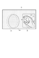
- the schematic diagram of the screen which displayed the moving image on the display part of the portable terminal in the said embodiment, and displayed the object image.
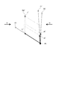
- the schematic diagram of the screen which displayed the optical flow in the said embodiment The schematic diagram for demonstrating the detection of a motion vector from the optical flow in the said embodiment.
- the schematic diagram for demonstrating the detection of a motion vector from the optical flow in the said embodiment The schematic diagram for demonstrating the detection of a motion vector from the optical flow in the said embodiment.
- transformation and movement of the object image which concern on 2nd Embodiment of this invention The schematic diagram for demonstrating a deformation
- FIG. 1 is a plan view showing an example of the mobile terminal 3 according to the embodiment of the present invention.
- the portable terminal 3 synthesizes and displays an object on the moving image captured by the imaging unit 35.
- Such a portable terminal 3 can be comprised by a smart phone (multifunctional mobile phone), a tablet terminal, a portable game machine, etc.
- the mobile terminal 3 includes a housing 31, a display unit 32, an operation unit 33, an audio output unit 34, an imaging unit 35, a storage unit 36, and a control unit 37 (see FIG. 2). And a terminal device capable of executing a game program.
- the casing 31 constitutes the exterior of the mobile terminal 3 and is formed in a substantially oval shape that is large enough to be held by the left and right hands.
- the housing 31 includes a front surface portion 31A, a back surface portion 31B (not shown in FIG. 1), an upper surface portion 31C, a bottom surface portion 31D, and left and right side surface portions 31E and 31F.
- the display unit 32 corresponds to the display device of the present invention, and is disposed at the approximate center of the front unit 31A.
- the display unit 32 includes a display panel formed in a rectangular shape, and an image formed by the display control unit 371 under the control of a display control unit 371 (see FIG. 3A) of the control unit 37 described later. Is displayed. Examples of such a display panel include organic EL (Electro-Luminescence) and liquid crystal display panels.
- the operation unit 33 includes various buttons and sticks arranged around the display unit 32 in the front surface 31A and the upper surface 31C of the housing 31, and controls operation signals in accordance with user input operations.
- the operation unit 33 is located on the left side with respect to the display unit 32, and can be input in each direction of up, down, left, and right when viewed facing the front unit 31A, and in each direction
- An operation stick 332 that can be tilted and an operation button 333 located on the bottom surface portion 31D side are provided.
- the operation unit 33 includes four operation buttons 334 positioned on the right side of the display unit 32, an operation stick 335 having the same configuration as the operation stick 332, and operation buttons 336 and 337 positioned on the bottom surface portion 31D side. And having.
- the operation unit 33 includes operation buttons 338L and 338R which are respectively located on the left and right sides of the upper surface portion 31C.
- the audio output unit 34 includes speakers 34L and 34R disposed near the left and right ends of the front portion 31A.
- the audio output unit 34 outputs audio corresponding to an audio signal input from an audio output control unit 373 (see FIG. 3A) of the control unit 37, which will be described later, through the speakers 34L and 34R.
- the imaging unit 35 corresponds to the imaging device of the present invention, and includes a camera 351 as a first imaging unit disposed on the upper right side of the front unit 31A.
- the imaging unit 35 outputs an image captured by the camera 351 to the control unit 37.
- FIG. 2 is a block diagram illustrating a configuration of the mobile terminal 3.
- the display unit 32, the operation unit 33, the audio output unit 34, the imaging unit 35, the storage unit 36, and the control unit 37 are connected to each other by a bus line BL.
- the storage unit 36 stores programs and data necessary for the operation of the mobile terminal 3.
- the storage unit 36 stores an OS (Operating System) that controls the operation of the mobile terminal 3, an application program such as a game, and an image display program.
- an application program such as a game
- an image display program Such a storage unit 36 can be configured by a non-volatile memory such as a flash memory or an HDD (Hard Disk Drive).
- the control unit 37 includes a CPU (Central Processing Unit) and the like, and controls the operation of the mobile terminal 3. Specifically, the control unit 37 reads out and processes the program stored in the storage unit 36 according to the user's input operation (operation signal input from the operation unit 33), or This is a control device that autonomously controls the mobile terminal 3. In addition, the control part 37 displays the moving image imaged by the imaging part 35 on the display part 32, when CPU runs the said image display program. Therefore, as shown in FIG.
- CPU Central Processing Unit
- control unit 37 includes a display control unit 371, an imaging control unit 372, an audio output control unit 373, an optical flow generation unit 374, a motion vector detection unit 375, an object operation unit 376, an operation region.
- a selection unit 377 and a masking unit 378 are provided.
- the display control unit 371 draws an image indicating the operation state of the mobile terminal 3 or an image captured by the imaging unit 35 in a drawing memory (not shown), and outputs an image signal corresponding to the image to the display unit 32. As a result, the image is displayed on the display unit 32. Specifically, as shown in FIG. 4, a moving image captured by the imaging unit 35 is displayed on the display unit 32, and an object image OB is synthesized and displayed on the moving image.
- the imaging control unit 372 controls the operation of the imaging unit 35. Specifically, the imaging control unit 372 causes the imaging unit 35 to capture images at a predetermined cycle (frame rate). Then, the imaging control unit 372 acquires a moving image that is a captured image input from the imaging unit 35 and stores the moving image in the storage unit 36.
- the audio output control unit 373 controls the audio output unit 34 to output a predetermined audio.
- the optical flow generation unit 374 generates an optical flow from at least two or more frame images G1 and G2 constituting a moving image. Now, assuming that the frame image G1 shown in FIG. 4 has transitioned to the frame image G2 shown in FIG. 5, the face image CH1 in the moving image slides in the right direction, and the finger portion image CH2 rotates. Assuming that The optical flow generator 374 generates an optical flow G3 as shown in FIG. 6 from the movement of the luminance points of the two frame images G1 and G2.
- the optical flow G3 can be obtained by using a known method such as a gradient method or a block matching method.
- the gradient method is a method of deriving a relational expression between spatiotemporal differentiation and optical flow from the assumption that the brightness of a point on an object does not change after movement, and using this to estimate the motion of the object.
- the block matching method an image is divided into small areas of a certain size, and a motion vector of each block is obtained. This is a method of searching where each block corresponds to the previous frame, and using a difference in position from the corresponding block as a motion vector.
- the optical flow G3 calculates the moving direction and moving speed of the images CH1 and CH2 from the two frame images G1 and G2 using the frame rate and the like, and generates a motion vector.
- the motion vector detection unit 375 detects a motion vector at a position where the object image OB is displayed in the optical flow G3 generated by the optical flow generation unit 374. In the change from FIG. 4 to FIG. 5, the image CH2 of the finger part is displayed around the object image OB, and the finger part is rotated leftward, and this is detected as the motion vector V1.
- the object operation unit 376 is a part that moves and deforms the object image OB based on the motion vector V1 around the object image OB detected by the motion vector detection unit 375.
- the object moving operation unit 376A calculates the moving direction and moving amount of the object image OB according to the detected direction and size of the motion vector V1, and displays the object image OB at an appropriate position on the display unit 32.
- the motion vector detection unit 375 causes the optical flow near the vertex of the polyhedron POL set in the object image OB.
- the motion vector V1 of the polyhedron POL is detected from the OF.
- the optical flow OF is obtained discretely for each pixel of the display unit 32.
- the optical flow of the vertex to be obtained is obtained by interpolation from the optical flow of surrounding pixel coordinates.
- the object movement operation unit 376A deforms the polyhedron POL and then sets the polyhedron POL to the original constraint condition between the vertices, as shown in FIG. 7B.
- FIG. 7C the polyhedron POL is rotated, and the object image OB is moved in accordance with the rotational movement of the polyhedron POL.
- the object deformation operation unit 376B calculates the deformation direction and deformation amount of the object image OB according to the direction and size of the motion vector V1 around the object image OB detected by the motion vector detection unit 375, and deforms the object image OB. Thus, it is synthesized and displayed on the display unit 32.
- the object deformation operation unit 376B includes a polyhedron setting unit 376C, a space division unit 376D, a space determination unit 376E, a decomposition coefficient storage unit 376F, and a deformation display unit 376G. Specifically, as shown in FIG. 8, when the image CH2 of the finger portion moves up and down on the object image OB, the object image OB is deformed up and down by the motion vector V1 on the display unit 32. To display.
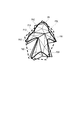
- the polyhedron setting unit 376C sets the center point P0 at an arbitrary position in the object image OB, and sets the polyhedron POL centered on the center point P0.
- the polyhedron POL is set as a convex polyhedron having twelve vertices P1 to P12.
- the present invention is not limited to this as long as the space can be uniquely divided into regions. It can be arbitrarily set according to the shape and the like.
- the polyhedron POL may be independent of the shape of the object image OB, and the polyhedron POL may be set using the vertex POB of the object image OB.
- the polyhedron POL is set so that the portion of the object image OB that is desired to move, such as a limb, covers the entire object image OB and is as small as possible.
- the space dividing unit 376D divides a space in the polyhedron POL into a plurality of vectors by a vector from the center point P0 to the vertices P1 to P12 of the polyhedron POL.
- the space discriminating unit 376E indicates that an arbitrary vertex POB of the object image OB is included in a space constituted by the center point P0, the vertex P1 of the polyhedron POL, the vertex P4, and the vertex P5.
- the deformation display unit 376G detects the motion vector V1 that deforms the polyhedron POL, as shown in FIG. 11, the deformation display unit 376G detects the space in the polyhedron POL according to the detected motion vector V1, the vertex P1, FIG. The vertex P4 and the vertex P5 are transformed into a vertex P1 ′, a vertex P4 ′, and a vertex P5 ′.
- the deformation display unit 376G stores the stored expression (1) in accordance with the motion vector V1, and the position x of an arbitrary vertex POB of the object image OB is represented by the following expression (2). 'Store and save, and display the deformed object image OB on the display unit 32.
- x ′ pa ′ + qb ′ + qc ′ (2)
- the object deformation operation unit 376B not only sets one polyhedron POL for the object image OB, but also converts the object image OB into a plurality of parts such as a head and limbs. Dividing into parts, setting part polyhedrons PA1 to PA5 for each part, and storing and saving the positions of arbitrary vertices of each part in the parts polyhedrons PA1 to PA5 in the form of the above formula (1) You can also.
- the deformation of the object image OB is realized by the following method. First, the lower part polyhedrons PA1 to PA5 are regarded as objects, and the part polyhedrons PA1 to PA5 are deformed and moved by deformation of the upper polyhedron POL.
- the object image OB is deformed and moved in accordance with the deformation of the lower component polyhedrons PA1 to PA5 to which the respective parts belong.
- the object image OB can be deformed by directly deforming the lower component polyhedrons PA1 to PA5 without setting the upper polyhedron POL.
- the deformation operation affects the entire object image OB, for example, when the object image OB is operated on a display image engulfed in the vortex of the sea, the upper polyhedron POL may be deformed or moved. .
- a complicated operation combining the upper polyhedron POL and the component polyhedrons PA1 to PA6 is also possible. That is, if the object image OB is assumed to be a display image that hits a rock or the like in a river or the like, the upper polyhedron POL performs a deformation movement operation in the river flow, and the deformation operation when hitting a rock is a component polyhedron. It can be carried out with PA1 to PA6. By adopting such a hierarchical structure, it is possible to match the deformation of the entire flow with the deformation of the part.
- Which part polyhedrons PA1 to PA5 belong to each part of the object image OB can be determined by the decomposition coefficient of each vector.
- Each part of the object image OB is selected so that the part polyhedrons PA1 to PA5 do not overlap each other.
- the decomposition coefficients p, q, and r in the equation (1) are set in the range of 0-1.
- the vertex P14 is also outside the component polyhedron PA4 as in the vertex P14 of the object image OB, the sum of squares of the decomposition coefficients p, q, r in the equation (1) is calculated as the component polyhedron PA3, PA4.
- the vertex P14 of the object image OB may be deformed as belonging to the smaller component polyhedron.
- the operation area selection unit 377 selects an area where the object image OB to be operated exists as the operation area AR.
- the operation area AR is selected using a known image recognition technique such as face recognition, excluding the optical flow in the area of the face image CH1 in FIG. It can also be selected by generating. Further, since the optical flow interval of the face image CH1 is widely detected and the finger image CH2 is generated narrowly, the operation area AR may be selected using this.
- the masking unit 378 is a means for facilitating the operation by masking the operation area AR.
- the moving image other than the operation area AR is not displayed, or the image of the operation area AR is not a moving image as it is, but the contrast is increased.
- the visibility of the operation area is improved by using an emphasized binary image, displaying only a contour image, or replacing it with an object image such as an icon.
- the display control unit 371 composites and displays the moving image captured by the imaging unit 35 and the object image OB read from the storage unit 36 on the display unit 32 (step S1).
- the optical flow generation unit 374 generates an optical flow G3 based on the frame images G1 and G2 constituting the moving image (step S2).
- the motion vector detection unit 375 monitors the optical flow G3 in the operation area AR (step S3), and detects the direction and magnitude of the motion vector V1 when the motion vector in the operation area AR has changed (step S3). S4).
- the object operation unit 376 calculates the moving direction and moving amount of the object image OB based on the detected motion vector V1, and displays the object image OB in an appropriate position on the display unit 32 (step S5).
- a series of object operation methods from step S1 to step S5 are stored in the storage unit 36 as a computer-readable program, and when the moving image captured by the imaging unit 35 is displayed on the display unit 32, the control unit It is read by 37 and executed.
- the moving operation of the object image OB is performed by the object operation unit 376. In performing the above, the moving operation of the object image OB can be smoothly performed according to the detected motion vector V1.
- the operation area AR is selected by the operation area selection unit 377, it is possible to prevent the operation of the object image OB from being obstructed by a motion vector other than the detection area.
- the masking unit 378 By providing the masking unit 378, the operation area AR is masked, so that the object image OB can be operated in a state that is easy for a viewer of the moving image to see.
- the object transformation operation unit 376B sets a polyhedron POL centered on an arbitrary center point P0 in the object image OB, and divides the space in the polyhedron POL by a vector from the center point P0 of the polyhedron POL toward the vertices P1 to P12. Then, it is determined in which of the divided spaces the vertex POB of the object image OB, and the decomposition coefficient of the position x of the object vertex is determined by three vectors constituting the space including the vertex of the object p, q, and r are stored, and the object image OB is deformed and displayed in accordance with the deformation operation applied to the polyhedron POL.
- the object deformation operation unit 376B can set the component polyhedrons PA1 to PA5 for each part of the object image OB and perform the deformation operation on each of the component polyhedrons PA1 to PA5, the object image OB can have a complicated shape. Even in such a case, the object image OB can be displayed in a deformed manner according to the deforming operation, and the processing load can be reduced.
- an optical flow G3 is generated from a moving image captured by the camera 351 of the imaging unit 35, a motion vector V1 is detected based on the generated optical flow G3, and based on the motion vector V1.
- the object image OB is deformed.
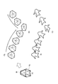
- the present embodiment is different in that a deformation animation of the vertex row of the polyhedron POL is created by an animation creation tool or the like, and the object image OB is followed by this.
- the polyhedron POL is set as a key frame image for the object image OB, as in the first embodiment.
- the key frame image is deformed, for example, when the key frame image shown in FIG. 14B and the key frame image shown in FIG.
- the image shown in FIG. 14 (C) is generated by interpolating with the difference image of the coordinates of the vertices to be caused to move, and stores and saves the deformation operation of the polyhedron POL as shown in FIGS.
- the object image OB is made to follow this animation, so that a deformed image of the object image OB as shown in FIGS. 14E to 14G can be displayed. Also by such a method, the same operation and effect as the first embodiment described above can be obtained.
- the polyhedron POL is deformed using the animation creation tool.
- the present embodiment is different in that the polyhedron POL is deformed and moved by using a physical simulation of the physics engine software as shown in FIG. That is, as shown in FIG. 15A, the polyhedron POL is set for the object image OB, as in the second embodiment.
- the polyhedron POL stores and saves the deformed state corresponding to the collision and movement in accordance with the natural law on the physics engine software.
- the physical simulation target may be a physical simulation of the relationship between vertices of the polyhedron POL itself. However, a physical simulation is performed on a rigid body composed of a plurality of vertices, and the rigid body as a simulation result is obtained. It is also possible to specify the polyhedron POL from the vertices constituting. When the object image OB is deformed and moved on the physics engine software, the number of vertices of the polyhedron POL is less than the number of vertices of the object image OB to be drawn.
- the deformation and movement image of the object image OB can be displayed by following the physical simulation deformation and movement of the polyhedron POL.
- the present invention is not limited to the embodiments described above, and includes modifications as described below.
- the object operation unit 376 operates the character-like object image OB.
- the present invention is not limited to this.
- the slide switch image OB2 as shown in FIG. An operation may be performed in which the image is fixed somewhere and slid on the image CH2 of the finger portion.
- the embodiments of the present invention can employ other configurations as long as the object of the present invention can be achieved.
- Vector detection unit 376 ... Object operation unit, 376A ... Object movement operation unit, 376B ... Object deformation operation unit 376C: polyhedron setting unit, 376D ... space division unit, 376E ... space discrimination unit, 376F ... decomposition coefficient storage unit, 37
- G Deformation display unit, 377 ... Operation region selection unit, 378 ... Masking unit, AR ... Operation region, BL ... Bus line, CH1, CH2 ... Image, G1, G2 ... Frame image, G3 ... Optical flow, OB ... Object image , OB2 ... Slide switch image
Landscapes
- Engineering & Computer Science (AREA)
- Multimedia (AREA)
- Human Computer Interaction (AREA)
- Theoretical Computer Science (AREA)
- Processing Or Creating Images (AREA)
Abstract
L'invention a trait à un procédé de manipulation d'un objet (OB), qui permet de manipuler, pour le déformer, un objet (OB) affiché sur un dispositif d'affichage. Selon ce procédé : un dispositif de commande servant à commander le dispositif d'affichage définit un polyèdre (POL) centré sur un point discrétionnaire (P0) à l'intérieur de l'objet (OB) ; un espace dans le polyèdre (POL) est divisé par des vecteurs partant du centre (P0) du polyèdre (POL) et se dirigeant vers les sommets (P1-P12) dudit polyèdre (POL) ; il est déterminé dans quel espace divisé est inclus le sommet de l'objet (OB) ; le coefficient de décomposition d'un sommet (POB) de l'objet (OB) est préservé par trois vecteurs constituant un espace qui comprend ledit sommet (POB) de l'objet (OB) ; l'objet (OB) est déformé conformément à une manipulation visant la déformation, qui est effectuée sur le polyèdre (POL), puis l'objet (OB) déformé est affiché.
Priority Applications (1)
| Application Number | Priority Date | Filing Date | Title |
|---|---|---|---|
| US15/119,814 US10080963B2 (en) | 2014-03-28 | 2015-03-20 | Object manipulation method, object manipulation program, and information processing apparatus |
Applications Claiming Priority (4)
| Application Number | Priority Date | Filing Date | Title |
|---|---|---|---|
| JP2014068752A JP6030594B2 (ja) | 2014-03-28 | 2014-03-28 | オブジェクトの変形操作方法、オブジェクトの変形操作プログラム、及び情報処理装置 |
| JP2014-068753 | 2014-03-28 | ||
| JP2014068753A JP2015191480A (ja) | 2014-03-28 | 2014-03-28 | 情報処理装置、オブジェクトの操作方法、及びオブジェクトの操作プログラム |
| JP2014-068752 | 2014-03-28 |
Publications (1)
| Publication Number | Publication Date |
|---|---|
| WO2015146813A1 true WO2015146813A1 (fr) | 2015-10-01 |
Family
ID=54195331
Family Applications (1)
| Application Number | Title | Priority Date | Filing Date |
|---|---|---|---|
| PCT/JP2015/058391 Ceased WO2015146813A1 (fr) | 2014-03-28 | 2015-03-20 | Procédé de manipulation d'objet, programme de manipulation d'objet et dispositif de traitement d'informations |
Country Status (2)
| Country | Link |
|---|---|
| US (1) | US10080963B2 (fr) |
| WO (1) | WO2015146813A1 (fr) |
Cited By (1)
| Publication number | Priority date | Publication date | Assignee | Title |
|---|---|---|---|---|
| CN109583391A (zh) * | 2018-12-04 | 2019-04-05 | 北京字节跳动网络技术有限公司 | 关键点检测方法、装置、设备及可读介质 |
Families Citing this family (1)
| Publication number | Priority date | Publication date | Assignee | Title |
|---|---|---|---|---|
| JP5955405B2 (ja) * | 2012-11-07 | 2016-07-20 | 株式会社日立製作所 | 管理対象システムを管理するシステム及びプログラム |
Citations (6)
| Publication number | Priority date | Publication date | Assignee | Title |
|---|---|---|---|---|
| JPH07281666A (ja) * | 1994-04-05 | 1995-10-27 | Casio Comput Co Ltd | 画像制御装置 |
| JP2000196914A (ja) * | 1998-10-13 | 2000-07-14 | Sony Electronics Inc | 動作検知インタ―フェ―ス |
| JP2001006003A (ja) * | 1999-06-25 | 2001-01-12 | Namco Ltd | 画像生成システム及び情報記憶媒体 |
| JP2005301479A (ja) * | 2004-04-08 | 2005-10-27 | Akinori Yoshino | 投影された提示者の動作による命令入力装置 |
| JP2007156950A (ja) * | 2005-12-07 | 2007-06-21 | Toyota Motor Corp | 車両用操作装置 |
| JP2009519552A (ja) * | 2005-12-12 | 2009-05-14 | 株式会社ソニー・コンピュータエンタテインメント | 相互対話的な電子的にシミュレートされた環境の音声および映像制御 |
Family Cites Families (23)
| Publication number | Priority date | Publication date | Assignee | Title |
|---|---|---|---|---|
| US5168677A (en) * | 1989-11-15 | 1992-12-08 | Ernesto Daniel Gyurec | Method of constructing flat building block modules from the union of two frustums by their congruent bases and slot connectors complement for a variety of constructive or amusing applications |
| JP3926866B2 (ja) * | 1996-05-10 | 2007-06-06 | 株式会社ソニー・コンピュータエンタテインメント | 情報処理装置、情報処理方法、及び描画システム |
| US8836701B1 (en) * | 1998-07-23 | 2014-09-16 | Freedesign, Inc. | Surface patch techniques for computational geometry |
| US6501515B1 (en) | 1998-10-13 | 2002-12-31 | Sony Corporation | Remote control system |
| JP2001100906A (ja) | 1999-09-30 | 2001-04-13 | Suzuki Motor Corp | 三次元データ表示装置 |
| US6700586B1 (en) | 2000-08-23 | 2004-03-02 | Nintendo Co., Ltd. | Low cost graphics with stitching processing hardware support for skeletal animation |
| JP4636741B2 (ja) * | 2001-07-06 | 2011-02-23 | 任天堂株式会社 | 画像処理装置および立体形状表示プログラム |
| US7002574B2 (en) * | 2002-12-27 | 2006-02-21 | Microsoft Corporation | Method and system for tessellating a polygon |
| JP4323180B2 (ja) | 2003-02-13 | 2009-09-02 | 日本電信電話株式会社 | 自己画像表示を用いたインタフェース方法、装置、およびプログラム |
| JP4723799B2 (ja) | 2003-07-08 | 2011-07-13 | 株式会社ソニー・コンピュータエンタテインメント | 制御システムおよび制御方法 |
| JP3847753B2 (ja) | 2004-01-30 | 2006-11-22 | 株式会社ソニー・コンピュータエンタテインメント | 画像処理装置、画像処理方法、記録媒体、コンピュータプログラム、半導体デバイス |
| US20050264554A1 (en) * | 2004-05-25 | 2005-12-01 | Deming James L | Tile based rendering of smooth points using polygons |
| JP2006244272A (ja) | 2005-03-04 | 2006-09-14 | Nippon Telegr & Teleph Corp <Ntt> | 手位置追跡方法、装置、およびプログラム |
| CN101636745A (zh) | 2006-12-29 | 2010-01-27 | 格斯图尔泰克股份有限公司 | 使用增强型交互系统操纵虚拟对象 |
| JP2009134693A (ja) | 2007-10-30 | 2009-06-18 | Canon Inc | 画像処理装置、画像処理方法 |
| JP5205187B2 (ja) | 2008-09-11 | 2013-06-05 | 株式会社エヌ・ティ・ティ・ドコモ | 入力システム及び入力方法 |
| JP5513973B2 (ja) | 2010-05-11 | 2014-06-04 | 日本放送協会 | 仮想力覚提示装置及び仮想力覚提示プログラム |
| JP5751775B2 (ja) | 2010-09-01 | 2015-07-22 | キヤノン株式会社 | 撮像装置、その制御方法及びプログラム並びに記録媒体 |
| JP5774387B2 (ja) | 2011-06-28 | 2015-09-09 | 京セラ株式会社 | 表示機器 |
| JP2013101526A (ja) | 2011-11-09 | 2013-05-23 | Sony Corp | 情報処理装置、表示制御方法、およびプログラム |
| US9350798B2 (en) * | 2013-12-10 | 2016-05-24 | Oracle International Corporation | Methods and systems for transitioning between arbitrary shapes |
| JP6338929B2 (ja) * | 2014-05-23 | 2018-06-06 | 東芝メモリ株式会社 | レチクルマーク配置方法およびレチクルマーク配置プログラム |
| EP3001370A1 (fr) * | 2014-09-29 | 2016-03-30 | Thomson Licensing | Procédé et système de contrôle de cohérence |
-
2015
- 2015-03-20 US US15/119,814 patent/US10080963B2/en active Active
- 2015-03-20 WO PCT/JP2015/058391 patent/WO2015146813A1/fr not_active Ceased
Patent Citations (6)
| Publication number | Priority date | Publication date | Assignee | Title |
|---|---|---|---|---|
| JPH07281666A (ja) * | 1994-04-05 | 1995-10-27 | Casio Comput Co Ltd | 画像制御装置 |
| JP2000196914A (ja) * | 1998-10-13 | 2000-07-14 | Sony Electronics Inc | 動作検知インタ―フェ―ス |
| JP2001006003A (ja) * | 1999-06-25 | 2001-01-12 | Namco Ltd | 画像生成システム及び情報記憶媒体 |
| JP2005301479A (ja) * | 2004-04-08 | 2005-10-27 | Akinori Yoshino | 投影された提示者の動作による命令入力装置 |
| JP2007156950A (ja) * | 2005-12-07 | 2007-06-21 | Toyota Motor Corp | 車両用操作装置 |
| JP2009519552A (ja) * | 2005-12-12 | 2009-05-14 | 株式会社ソニー・コンピュータエンタテインメント | 相互対話的な電子的にシミュレートされた環境の音声および映像制御 |
Cited By (1)
| Publication number | Priority date | Publication date | Assignee | Title |
|---|---|---|---|---|
| CN109583391A (zh) * | 2018-12-04 | 2019-04-05 | 北京字节跳动网络技术有限公司 | 关键点检测方法、装置、设备及可读介质 |
Also Published As
| Publication number | Publication date |
|---|---|
| US10080963B2 (en) | 2018-09-25 |
| US20170056774A1 (en) | 2017-03-02 |
Similar Documents
| Publication | Publication Date | Title |
|---|---|---|
| US11430192B2 (en) | Placement and manipulation of objects in augmented reality environment | |
| US11262835B2 (en) | Human-body-gesture-based region and volume selection for HMD | |
| US10678340B2 (en) | System and method for providing user interface tools | |
| CN106355153B (zh) | 一种基于增强现实的虚拟对象显示方法、装置以及系统 | |
| JP4533087B2 (ja) | 画像処理方法、画像処理装置 | |
| US8487871B2 (en) | Virtual desktop coordinate transformation | |
| US20120326966A1 (en) | Gesture-controlled technique to expand interaction radius in computer vision applications | |
| US10359906B2 (en) | Haptic interface for population of a three-dimensional virtual environment | |
| KR20150026396A (ko) | 이미지를 합성하기 위한 방법 및 그 전자 장치 | |
| WO2015146813A1 (fr) | Procédé de manipulation d'objet, programme de manipulation d'objet et dispositif de traitement d'informations | |
| US10553249B2 (en) | Storage medium, information processing apparatus, information processing system and information processing method | |
| JP2013162221A (ja) | 情報処理装置、情報処理方法、情報処理プログラム | |
| JP6030594B2 (ja) | オブジェクトの変形操作方法、オブジェクトの変形操作プログラム、及び情報処理装置 | |
| US20180059811A1 (en) | Display control device, display control method, and recording medium | |
| JP2019101192A5 (fr) | ||
| JP2022112769A5 (ja) | プログラム、およびシステム | |
| JP2015191480A (ja) | 情報処理装置、オブジェクトの操作方法、及びオブジェクトの操作プログラム | |
| JP5325253B2 (ja) | 画像処理装置、画像処理装置の制御方法、及びプログラム | |
| CN119759471A (zh) | 动效显示方法及相关装置 | |
| CN110941974B (zh) | 虚拟对象的控制方法和装置 | |
| CN121957745A (zh) | 开屏动画显示方法及电子设备 | |
| KR20110092029A (ko) | 복수 영상 투사를 위한 폐회로 기반의 인터랙티브 영상 투사 제어 장치 및 방법 |
Legal Events
| Date | Code | Title | Description |
|---|---|---|---|
| 121 | Ep: the epo has been informed by wipo that ep was designated in this application |
Ref document number: 15767759 Country of ref document: EP Kind code of ref document: A1 |
|
| WWE | Wipo information: entry into national phase |
Ref document number: 15119814 Country of ref document: US |
|
| NENP | Non-entry into the national phase | ||
| 122 | Ep: pct application non-entry in european phase |
Ref document number: 15767759 Country of ref document: EP Kind code of ref document: A1 |