WO2015146889A1 - Système de réception d'énergie - Google Patents
Système de réception d'énergie Download PDFInfo
- Publication number
- WO2015146889A1 WO2015146889A1 PCT/JP2015/058688 JP2015058688W WO2015146889A1 WO 2015146889 A1 WO2015146889 A1 WO 2015146889A1 JP 2015058688 W JP2015058688 W JP 2015058688W WO 2015146889 A1 WO2015146889 A1 WO 2015146889A1
- Authority
- WO
- WIPO (PCT)
- Prior art keywords
- power
- antenna coil
- power receiving
- vehicle
- shield plate
- Prior art date
- Legal status (The legal status is an assumption and is not a legal conclusion. Google has not performed a legal analysis and makes no representation as to the accuracy of the status listed.)
- Ceased
Links
Images


Classifications
-
- H—ELECTRICITY
- H02—GENERATION; CONVERSION OR DISTRIBUTION OF ELECTRIC POWER
- H02J—ELECTRIC POWER NETWORKS; CIRCUIT ARRANGEMENTS OR SYSTEMS FOR SUPPLYING OR DISTRIBUTING ELECTRIC POWER; SYSTEMS FOR STORING ELECTRIC ENERGY
- H02J50/00—Circuit arrangements or systems for wireless supply or distribution of electric power
- H02J50/10—Circuit arrangements or systems for wireless supply or distribution of electric power using inductive coupling
- H02J50/12—Circuit arrangements or systems for wireless supply or distribution of electric power using inductive coupling of the resonant type
-
- B—PERFORMING OPERATIONS; TRANSPORTING
- B60—VEHICLES IN GENERAL
- B60L—PROPULSION OF ELECTRICALLY-PROPELLED VEHICLES; SUPPLYING ELECTRIC POWER FOR AUXILIARY EQUIPMENT OF ELECTRICALLY-PROPELLED VEHICLES; ELECTRODYNAMIC BRAKE SYSTEMS FOR VEHICLES IN GENERAL; MAGNETIC SUSPENSION OR LEVITATION FOR VEHICLES; MONITORING OPERATING VARIABLES OF ELECTRICALLY-PROPELLED VEHICLES; ELECTRIC SAFETY DEVICES FOR ELECTRICALLY-PROPELLED VEHICLES
- B60L1/00—Supplying electric power to auxiliary equipment of vehicles
- B60L1/02—Supplying electric power to auxiliary equipment of vehicles to electric heating circuits
- B60L1/04—Supplying electric power to auxiliary equipment of vehicles to electric heating circuits fed by the power supply line
- B60L1/06—Supplying electric power to auxiliary equipment of vehicles to electric heating circuits fed by the power supply line using only one supply
-
- B—PERFORMING OPERATIONS; TRANSPORTING
- B60—VEHICLES IN GENERAL
- B60L—PROPULSION OF ELECTRICALLY-PROPELLED VEHICLES; SUPPLYING ELECTRIC POWER FOR AUXILIARY EQUIPMENT OF ELECTRICALLY-PROPELLED VEHICLES; ELECTRODYNAMIC BRAKE SYSTEMS FOR VEHICLES IN GENERAL; MAGNETIC SUSPENSION OR LEVITATION FOR VEHICLES; MONITORING OPERATING VARIABLES OF ELECTRICALLY-PROPELLED VEHICLES; ELECTRIC SAFETY DEVICES FOR ELECTRICALLY-PROPELLED VEHICLES
- B60L50/00—Electric propulsion with power supplied within the vehicle
- B60L50/10—Electric propulsion with power supplied within the vehicle using propulsion power supplied by engine-driven generators, e.g. generators driven by combustion engines
- B60L50/16—Electric propulsion with power supplied within the vehicle using propulsion power supplied by engine-driven generators, e.g. generators driven by combustion engines with provision for separate direct mechanical propulsion
-
- B—PERFORMING OPERATIONS; TRANSPORTING
- B60—VEHICLES IN GENERAL
- B60L—PROPULSION OF ELECTRICALLY-PROPELLED VEHICLES; SUPPLYING ELECTRIC POWER FOR AUXILIARY EQUIPMENT OF ELECTRICALLY-PROPELLED VEHICLES; ELECTRODYNAMIC BRAKE SYSTEMS FOR VEHICLES IN GENERAL; MAGNETIC SUSPENSION OR LEVITATION FOR VEHICLES; MONITORING OPERATING VARIABLES OF ELECTRICALLY-PROPELLED VEHICLES; ELECTRIC SAFETY DEVICES FOR ELECTRICALLY-PROPELLED VEHICLES
- B60L50/00—Electric propulsion with power supplied within the vehicle
- B60L50/40—Electric propulsion with power supplied within the vehicle using propulsion power supplied by capacitors
-
- B—PERFORMING OPERATIONS; TRANSPORTING
- B60—VEHICLES IN GENERAL
- B60L—PROPULSION OF ELECTRICALLY-PROPELLED VEHICLES; SUPPLYING ELECTRIC POWER FOR AUXILIARY EQUIPMENT OF ELECTRICALLY-PROPELLED VEHICLES; ELECTRODYNAMIC BRAKE SYSTEMS FOR VEHICLES IN GENERAL; MAGNETIC SUSPENSION OR LEVITATION FOR VEHICLES; MONITORING OPERATING VARIABLES OF ELECTRICALLY-PROPELLED VEHICLES; ELECTRIC SAFETY DEVICES FOR ELECTRICALLY-PROPELLED VEHICLES
- B60L50/00—Electric propulsion with power supplied within the vehicle
- B60L50/50—Electric propulsion with power supplied within the vehicle using propulsion power supplied by batteries or fuel cells
- B60L50/51—Electric propulsion with power supplied within the vehicle using propulsion power supplied by batteries or fuel cells characterised by AC-motors
-
- B—PERFORMING OPERATIONS; TRANSPORTING
- B60—VEHICLES IN GENERAL
- B60L—PROPULSION OF ELECTRICALLY-PROPELLED VEHICLES; SUPPLYING ELECTRIC POWER FOR AUXILIARY EQUIPMENT OF ELECTRICALLY-PROPELLED VEHICLES; ELECTRODYNAMIC BRAKE SYSTEMS FOR VEHICLES IN GENERAL; MAGNETIC SUSPENSION OR LEVITATION FOR VEHICLES; MONITORING OPERATING VARIABLES OF ELECTRICALLY-PROPELLED VEHICLES; ELECTRIC SAFETY DEVICES FOR ELECTRICALLY-PROPELLED VEHICLES
- B60L53/00—Methods of charging batteries, specially adapted for electric vehicles; Charging stations or on-board charging equipment therefor; Exchange of energy storage elements in electric vehicles
- B60L53/10—Methods of charging batteries, specially adapted for electric vehicles; Charging stations or on-board charging equipment therefor; Exchange of energy storage elements in electric vehicles characterised by the energy transfer between the charging station and the vehicle
- B60L53/12—Inductive energy transfer
-
- B—PERFORMING OPERATIONS; TRANSPORTING
- B60—VEHICLES IN GENERAL
- B60L—PROPULSION OF ELECTRICALLY-PROPELLED VEHICLES; SUPPLYING ELECTRIC POWER FOR AUXILIARY EQUIPMENT OF ELECTRICALLY-PROPELLED VEHICLES; ELECTRODYNAMIC BRAKE SYSTEMS FOR VEHICLES IN GENERAL; MAGNETIC SUSPENSION OR LEVITATION FOR VEHICLES; MONITORING OPERATING VARIABLES OF ELECTRICALLY-PROPELLED VEHICLES; ELECTRIC SAFETY DEVICES FOR ELECTRICALLY-PROPELLED VEHICLES
- B60L58/00—Methods or circuit arrangements for monitoring or controlling batteries or fuel cells, specially adapted for electric vehicles
- B60L58/10—Methods or circuit arrangements for monitoring or controlling batteries or fuel cells, specially adapted for electric vehicles for monitoring or controlling batteries
- B60L58/18—Methods or circuit arrangements for monitoring or controlling batteries or fuel cells, specially adapted for electric vehicles for monitoring or controlling batteries of two or more battery modules
- B60L58/21—Methods or circuit arrangements for monitoring or controlling batteries or fuel cells, specially adapted for electric vehicles for monitoring or controlling batteries of two or more battery modules having the same nominal voltage
-
- H—ELECTRICITY
- H01—ELECTRIC ELEMENTS
- H01F—MAGNETS; INDUCTANCES; TRANSFORMERS; SELECTION OF MATERIALS FOR THEIR MAGNETIC PROPERTIES
- H01F27/00—Details of transformers or inductances, in general
- H01F27/34—Special means for preventing or reducing unwanted electric or magnetic effects, e.g. no-load losses, reactive currents, harmonics, oscillations, leakage fields
- H01F27/36—Electric or magnetic shields or screens
-
- H—ELECTRICITY
- H01—ELECTRIC ELEMENTS
- H01F—MAGNETS; INDUCTANCES; TRANSFORMERS; SELECTION OF MATERIALS FOR THEIR MAGNETIC PROPERTIES
- H01F27/00—Details of transformers or inductances, in general
- H01F27/34—Special means for preventing or reducing unwanted electric or magnetic effects, e.g. no-load losses, reactive currents, harmonics, oscillations, leakage fields
- H01F27/36—Electric or magnetic shields or screens
- H01F27/366—Electric or magnetic shields or screens made of ferromagnetic material
-
- H—ELECTRICITY
- H01—ELECTRIC ELEMENTS
- H01F—MAGNETS; INDUCTANCES; TRANSFORMERS; SELECTION OF MATERIALS FOR THEIR MAGNETIC PROPERTIES
- H01F38/00—Adaptations of transformers or inductances for specific applications or functions
- H01F38/14—Inductive couplings
-
- H—ELECTRICITY
- H02—GENERATION; CONVERSION OR DISTRIBUTION OF ELECTRIC POWER
- H02J—ELECTRIC POWER NETWORKS; CIRCUIT ARRANGEMENTS OR SYSTEMS FOR SUPPLYING OR DISTRIBUTING ELECTRIC POWER; SYSTEMS FOR STORING ELECTRIC ENERGY
- H02J50/00—Circuit arrangements or systems for wireless supply or distribution of electric power
- H02J50/70—Circuit arrangements or systems for wireless supply or distribution of electric power involving the reduction of electric, magnetic or electromagnetic leakage fields
-
- H—ELECTRICITY
- H02—GENERATION; CONVERSION OR DISTRIBUTION OF ELECTRIC POWER
- H02J—ELECTRIC POWER NETWORKS; CIRCUIT ARRANGEMENTS OR SYSTEMS FOR SUPPLYING OR DISTRIBUTING ELECTRIC POWER; SYSTEMS FOR STORING ELECTRIC ENERGY
- H02J7/00—Circuit arrangements for charging or discharging batteries or for supplying loads from batteries
- H02J7/70—Circuit arrangements for charging or discharging batteries or for supplying loads from batteries characterised by the mechanical construction
-
- B—PERFORMING OPERATIONS; TRANSPORTING
- B60—VEHICLES IN GENERAL
- B60L—PROPULSION OF ELECTRICALLY-PROPELLED VEHICLES; SUPPLYING ELECTRIC POWER FOR AUXILIARY EQUIPMENT OF ELECTRICALLY-PROPELLED VEHICLES; ELECTRODYNAMIC BRAKE SYSTEMS FOR VEHICLES IN GENERAL; MAGNETIC SUSPENSION OR LEVITATION FOR VEHICLES; MONITORING OPERATING VARIABLES OF ELECTRICALLY-PROPELLED VEHICLES; ELECTRIC SAFETY DEVICES FOR ELECTRICALLY-PROPELLED VEHICLES
- B60L2210/00—Converter types
- B60L2210/30—AC to DC converters
-
- B—PERFORMING OPERATIONS; TRANSPORTING
- B60—VEHICLES IN GENERAL
- B60L—PROPULSION OF ELECTRICALLY-PROPELLED VEHICLES; SUPPLYING ELECTRIC POWER FOR AUXILIARY EQUIPMENT OF ELECTRICALLY-PROPELLED VEHICLES; ELECTRODYNAMIC BRAKE SYSTEMS FOR VEHICLES IN GENERAL; MAGNETIC SUSPENSION OR LEVITATION FOR VEHICLES; MONITORING OPERATING VARIABLES OF ELECTRICALLY-PROPELLED VEHICLES; ELECTRIC SAFETY DEVICES FOR ELECTRICALLY-PROPELLED VEHICLES
- B60L2210/00—Converter types
- B60L2210/40—DC to AC converters
-
- B—PERFORMING OPERATIONS; TRANSPORTING
- B60—VEHICLES IN GENERAL
- B60L—PROPULSION OF ELECTRICALLY-PROPELLED VEHICLES; SUPPLYING ELECTRIC POWER FOR AUXILIARY EQUIPMENT OF ELECTRICALLY-PROPELLED VEHICLES; ELECTRODYNAMIC BRAKE SYSTEMS FOR VEHICLES IN GENERAL; MAGNETIC SUSPENSION OR LEVITATION FOR VEHICLES; MONITORING OPERATING VARIABLES OF ELECTRICALLY-PROPELLED VEHICLES; ELECTRIC SAFETY DEVICES FOR ELECTRICALLY-PROPELLED VEHICLES
- B60L2270/00—Problem solutions or means not otherwise provided for
- B60L2270/10—Emission reduction
- B60L2270/14—Emission reduction of noise
- B60L2270/145—Structure borne vibrations
-
- B—PERFORMING OPERATIONS; TRANSPORTING
- B60—VEHICLES IN GENERAL
- B60L—PROPULSION OF ELECTRICALLY-PROPELLED VEHICLES; SUPPLYING ELECTRIC POWER FOR AUXILIARY EQUIPMENT OF ELECTRICALLY-PROPELLED VEHICLES; ELECTRODYNAMIC BRAKE SYSTEMS FOR VEHICLES IN GENERAL; MAGNETIC SUSPENSION OR LEVITATION FOR VEHICLES; MONITORING OPERATING VARIABLES OF ELECTRICALLY-PROPELLED VEHICLES; ELECTRIC SAFETY DEVICES FOR ELECTRICALLY-PROPELLED VEHICLES
- B60L2270/00—Problem solutions or means not otherwise provided for
- B60L2270/10—Emission reduction
- B60L2270/14—Emission reduction of noise
- B60L2270/147—Emission reduction of noise electro magnetic [EMI]
-
- Y—GENERAL TAGGING OF NEW TECHNOLOGICAL DEVELOPMENTS; GENERAL TAGGING OF CROSS-SECTIONAL TECHNOLOGIES SPANNING OVER SEVERAL SECTIONS OF THE IPC; TECHNICAL SUBJECTS COVERED BY FORMER USPC CROSS-REFERENCE ART COLLECTIONS [XRACs] AND DIGESTS
- Y02—TECHNOLOGIES OR APPLICATIONS FOR MITIGATION OR ADAPTATION AGAINST CLIMATE CHANGE
- Y02T—CLIMATE CHANGE MITIGATION TECHNOLOGIES RELATED TO TRANSPORTATION
- Y02T10/00—Road transport of goods or passengers
- Y02T10/60—Other road transportation technologies with climate change mitigation effect
- Y02T10/70—Energy storage systems for electromobility, e.g. batteries
-
- Y—GENERAL TAGGING OF NEW TECHNOLOGICAL DEVELOPMENTS; GENERAL TAGGING OF CROSS-SECTIONAL TECHNOLOGIES SPANNING OVER SEVERAL SECTIONS OF THE IPC; TECHNICAL SUBJECTS COVERED BY FORMER USPC CROSS-REFERENCE ART COLLECTIONS [XRACs] AND DIGESTS
- Y02—TECHNOLOGIES OR APPLICATIONS FOR MITIGATION OR ADAPTATION AGAINST CLIMATE CHANGE
- Y02T—CLIMATE CHANGE MITIGATION TECHNOLOGIES RELATED TO TRANSPORTATION
- Y02T10/00—Road transport of goods or passengers
- Y02T10/60—Other road transportation technologies with climate change mitigation effect
- Y02T10/7072—Electromobility specific charging systems or methods for batteries, ultracapacitors, supercapacitors or double-layer capacitors
-
- Y—GENERAL TAGGING OF NEW TECHNOLOGICAL DEVELOPMENTS; GENERAL TAGGING OF CROSS-SECTIONAL TECHNOLOGIES SPANNING OVER SEVERAL SECTIONS OF THE IPC; TECHNICAL SUBJECTS COVERED BY FORMER USPC CROSS-REFERENCE ART COLLECTIONS [XRACs] AND DIGESTS
- Y02—TECHNOLOGIES OR APPLICATIONS FOR MITIGATION OR ADAPTATION AGAINST CLIMATE CHANGE
- Y02T—CLIMATE CHANGE MITIGATION TECHNOLOGIES RELATED TO TRANSPORTATION
- Y02T10/00—Road transport of goods or passengers
- Y02T10/60—Other road transportation technologies with climate change mitigation effect
- Y02T10/72—Electric energy management in electromobility
-
- Y—GENERAL TAGGING OF NEW TECHNOLOGICAL DEVELOPMENTS; GENERAL TAGGING OF CROSS-SECTIONAL TECHNOLOGIES SPANNING OVER SEVERAL SECTIONS OF THE IPC; TECHNICAL SUBJECTS COVERED BY FORMER USPC CROSS-REFERENCE ART COLLECTIONS [XRACs] AND DIGESTS
- Y02—TECHNOLOGIES OR APPLICATIONS FOR MITIGATION OR ADAPTATION AGAINST CLIMATE CHANGE
- Y02T—CLIMATE CHANGE MITIGATION TECHNOLOGIES RELATED TO TRANSPORTATION
- Y02T90/00—Enabling technologies or technologies with a potential or indirect contribution to GHG emissions mitigation
- Y02T90/10—Technologies relating to charging of electric vehicles
- Y02T90/12—Electric charging stations
-
- Y—GENERAL TAGGING OF NEW TECHNOLOGICAL DEVELOPMENTS; GENERAL TAGGING OF CROSS-SECTIONAL TECHNOLOGIES SPANNING OVER SEVERAL SECTIONS OF THE IPC; TECHNICAL SUBJECTS COVERED BY FORMER USPC CROSS-REFERENCE ART COLLECTIONS [XRACs] AND DIGESTS
- Y02—TECHNOLOGIES OR APPLICATIONS FOR MITIGATION OR ADAPTATION AGAINST CLIMATE CHANGE
- Y02T—CLIMATE CHANGE MITIGATION TECHNOLOGIES RELATED TO TRANSPORTATION
- Y02T90/00—Enabling technologies or technologies with a potential or indirect contribution to GHG emissions mitigation
- Y02T90/10—Technologies relating to charging of electric vehicles
- Y02T90/14—Plug-in electric vehicles
Definitions
- the present invention relates to a power receiving system that receives electric power supplied wirelessly to a power receiving circuit provided at the bottom of a vehicle.
- Electric devices and electric devices that can be moved without being installed in one place such as mobile phones, personal information terminals (PDAs), electric assist bicycles, electric vehicles, and hybrid vehicles, have power storage devices such as secondary batteries inside. ing.
- Such charging of the power storage device is often performed, for example, by connecting a charging port provided in an apparatus or device and a power supply device with a cable or the like.
- a technique for supplying power wirelessly without using such a cable that is, contactless, has been attracting attention.
- One of the technologies for supplying electric power in a non-contact manner uses magnetic field resonance.
- Magnetic field resonance is a resonance between a pair of resonance circuits having a common natural frequency (resonance frequency), for example, a resonance circuit on the power supply equipment side and a resonance circuit on the equipment or device side via a magnetic field.
- This is a technology for transmitting power through the network.
- Patent Document 1 discloses a technology that uses this magnetic field resonance to supply power to a vehicle in a non-contact manner from a power source outside the vehicle.
- a magnetic field generated around a coil unit including a resonance coil (antenna coil) provided in a resonance circuit and serving as an antenna may cause electromagnetic noise.
- an electronic device or the like mounted on a vehicle may be affected by electromagnetic noise.
- the conductor when a conductor such as a metal exists in the magnetic field, the conductor may be heated.
- the coil unit is installed at the bottom of the vehicle, the metal parts at the bottom of the vehicle may be heated. For this reason, sufficient magnetic flux is generated to form a magnetic field for coupling the resonance circuit on the power feeding side and the resonance circuit on the power reception side, and the magnetic flux that is not necessary for coupling between the resonance circuits is reduced so as not to leak as much as possible. It is preferable.
- the coil unit can be reduced in size by providing a shield member on the opposite side to the power transmission direction in the vicinity of the antenna coil.
- the antenna coil on the power feeding side and the antenna coil on the power receiving side do not necessarily face each other at a position (specified position) with the best transmission efficiency.
- a power receiving system for receiving electric power supplied wirelessly to a power receiving circuit provided at the bottom of a vehicle, A coil formed by winding a conductor wire around a reference axis, provided in the power receiving circuit, and a power receiving antenna coil that receives power transmitted through a magnetic field; On the non-transmission direction side that is the opposite side to the transmission direction side that is one side along the reference axis in the power reception side antenna coil, a first made of a magnetic material disposed along the radial direction of the power reception side antenna coil.
- a power-receiving-side antenna coil unit including a shield plate; A second shield plate made of a conductive material having a shape along the concave-convex shape of the target region including a concave portion recessed above the bottom surface of the vehicle body of the vehicle, The power-receiving-side antenna coil unit is disposed at a position overlapping the concave portion when viewed in the direction along the reference axis.
- the second shield plate made of a conductive material is installed in a target area including a recess recessed above the bottom surface of the vehicle body.
- the second shield plate is installed relatively upward on the bottom surface of the vehicle body. Therefore, it becomes easy to provide a gap between the power receiving side antenna coil unit installed at the bottom of the vehicle and the second shield plate.
- the first shield plate is included in the power receiving side antenna coil unit, it is easy to provide a gap between the second shield plate and the first shield plate. As a result, it is possible to suppress a disturbing current flowing in a direction that interferes with a current generated during power transmission from occurring in the second shield plate, and it is possible to suppress a decrease in power transmission efficiency.
- the size of the second shield plate can be set and attached to the vehicle in consideration of the shift of the relative position with the antenna coil on the power feeding side.
- the magnetic flux that causes the second shield plate to generate a current that flows in a direction that hinders the current that is generated during power transmission is a magnetic flux that links the receiving-side antenna coil. Therefore, it is preferable if the power receiving side antenna coil can be installed within the range of the concave portion where a gap is easily provided between the second shield plate and the power receiving side antenna coil unit including the power receiving side antenna coil. As one aspect, it is preferable that the power receiving system has the concave portion larger than the outer shape of the power receiving side antenna coil when viewed in a direction along the reference axis.
- the first shield plate is provided so as to suppress the magnetic flux interlinking with the power receiving antenna coil from affecting the vehicle side. And the quantity which the disturbance current which flows in the direction which obstructs the electric current which arises at the time of electric power transmission arises in the 2nd shield board decreases, so that the distance of the 1st shield board and the 2nd shield board is separated. Therefore, it is preferable if the power receiving side antenna coil unit can be installed within the range of the concave portion where it is easy to provide a gap between the second shield plate and the power receiving side antenna coil unit including the first shield plate. As one aspect, it is preferable that the power receiving system has the concave portion larger than the outer shape of the power receiving side antenna coil unit when viewed in the direction along the reference axis.
- the power-receiving-side antenna coil unit is provided at the bottom of the vehicle, it is preferable that the power-receiving-side antenna coil unit is attached so as to reduce contact with obstacles on the ground. That is, it is preferable that the minimum ground clearance set for the vehicle can be secured even when the power receiving side antenna coil unit is attached to the vehicle.
- the power receiving side antenna coil unit in the power receiving system is configured such that the lowest position when attached to the vehicle is higher than the lowest part of the bottom of the vehicle. It is preferable that it is attached to.
- the wireless power feeding system 1 includes a power feeding system 2 installed in a power feeding facility and a power receiving system 3 mounted on the vehicle 9 side.
- the power feeding system 2 is installed near the ground G if it is an outdoor facility, or near the floor surface if it is an indoor facility.
- the power receiving system 3 receives electric power supplied wirelessly from the power feeding system 2 to a power receiving circuit (for example, a power receiving side resonance circuit 35 described later) provided at the bottom of the vehicle 9.
- the power feeding system 2 includes an AC power source 21, a driver circuit 22, and a power feeding side resonance circuit 25 (power feeding circuit).
- the power supply side resonance circuit 25 includes a power supply side resonance coil 24 (power supply side antenna coil).
- the power receiving system 3 includes a power receiving side resonance circuit 35 (power receiving circuit), a rectifier circuit 32, and a power storage device 31.
- the power reception side resonance circuit 35 includes a power reception side resonance coil 34 (power reception side antenna coil).
- the power supply side resonance circuit 25 and the power reception side resonance circuit 35 are resonance circuits having the same natural frequency (resonance frequency), and are collectively referred to as a resonance circuit 5.
- the power supply side resonance coil 24 and the power reception side resonance coil 34 are collectively referred to as a resonance coil or an antenna coil 4.
- the antenna coil 4 is a coil formed by rotating the conductor wire 40 around the reference axis X (X2, X3).
- the power supply side resonance coil 24 (power supply side antenna coil) provided in the power supply side resonance circuit 25 (power supply circuit) is formed by rotating the conductor wire 40 around the reference axis “X2”, and transmits power via a magnetic field. Yes (send).
- the power receiving side resonance coil 34 (power receiving side antenna coil) provided in the power receiving side resonance circuit 35 (power receiving circuit) is formed by circulating the conductor wire 40 around the reference axis “X3” and is transmitted via a magnetic field. Receive power.
- the AC power supply 21 of the power supply system 2 is, for example, a power supply (system power supply) supplied from a commercial distribution network owned by an electric power company, and the frequency thereof is, for example, 50 Hz or 60 Hz.
- the driver circuit 22 is a circuit that converts the frequency of the system power supply of 50 Hz or 60 Hz into the resonance frequency of the power supply side resonance circuit 25 (resonance circuit 5), and is configured by a high frequency power supply circuit.
- the power storage device 31 of the power receiving system 3 is a DC power source that can be charged and discharged.
- a secondary battery such as lithium ion or nickel hydride or a capacitor is used.
- the power received by the power reception side resonance circuit 35 is AC power having the resonance frequency of the power reception side resonance circuit 35.
- the rectifier circuit 32 rectifies AC power having this resonance frequency into DC power.
- the circuit including the driver circuit 22 and the power supply side resonance circuit 25 or the power supply system 2 as a whole corresponds to a power supply circuit in a broad sense.
- the power supply side resonance circuit 25 corresponds to a power supply circuit in a narrow sense.
- the circuit including the power receiving side resonance circuit 35 and the rectifier circuit or the entire power receiving system 3 corresponds to a power receiving circuit in a broad sense.
- the power receiving side resonance circuit 35 corresponds to a power receiving circuit in a narrow sense.
- the vehicle 9 is, for example, an electric vehicle driven by a rotating electrical machine 91 or a hybrid vehicle driven by an internal combustion engine (not shown) and the rotating electrical machine 91.
- the rotating electrical machine 91 is connected to the power storage device 31 via a rotating electrical machine drive device such as an inverter 92, for example.
- the rotating electrical machine 91 is, for example, a three-phase AC rotating electrical machine, and the rotating electrical machine driving device is configured with an inverter 92 that converts power between direct current and alternating current as a core.
- the rotating electrical machine 91 can function as an electric motor and a generator.
- the wireless power supply system 1 is a system that resonates a pair of resonance circuits 5 (25, 35) via a magnetic field and supplies power via the magnetic field.
- MRI magnetic resonance imaging
- the two resonance circuits 5 are resonated via the “magnetic field”.
- the transmission method of the wireless power feeding system 1 that transmits power using resonance in a magnetic field is referred to as “electromagnetic resonance coupling method” or “magnetic resonance method”. Called. Further, this transmission method is different from the so-called “electromagnetic induction method”.
- the power supply side resonance circuit 25 and the power reception side resonance circuit 35 are circuits having the same resonance frequency.
- the other tuning fork when one of two tuning forks arranged apart from each other is vibrated in the air, the other tuning fork also vibrates in resonance with vibration propagated through the air.
- 25 and the power receiving resonance circuit 35 also resonate. More specifically, the power receiving side resonance circuit 35 resonates in resonance with the electromagnetic vibration propagated to the power receiving side resonance circuit 35 via the magnetic field generated by the resonance (electromagnetic vibration) of the power supply side resonance circuit 25 (electromagnetic). To vibrate).
- the power supply side resonance circuit 25 and the power reception side resonance circuit 35 are configured as LC resonators.
- the resonance circuit 5 includes an antenna coil 4 having an inductance component “L” and a capacitor 6 having a capacitance component “C”, for example, as shown in the equivalent circuit of FIG.
- the wireless power feeding system 1 when the wireless power feeding system 1 performs wireless power feeding from the power feeding circuit to the power receiving circuit via a magnetic field, the wireless power feeding system 1 performs power transmission with high efficiency while suppressing leakage of electromagnetic waves to spaces other than the space necessary for power transmission. It is preferable to be able to do so.
- the antenna coil unit 10 is comprised including the antenna coil 4 and the 1st shield board 81 made from a magnetic material.
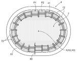
- the antenna coil 4 for power transmission that wirelessly feeds power from the power feeding circuit to the power receiving circuit is an antenna having a plurality of (in this case, odd number) arms 72 as shown in FIG.
- a coil 41 having a conductor wire 40 wound around the frame 7 in a flat spiral shape is used as a core.
- the antenna frame 7 is made of a material having a low dielectric loss tangent (tan ⁇ ) and a low dielectric constant, such as polypropylene, polycarbonate, polyethylene, or the like.
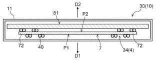
- the antenna frame 7 has a transmission surface P1 on one side with respect to the radiation surface along the radiation direction of the arm 72, and an anti-transmission surface P2 on the opposite side to the transmission surface P1.
- the conductor wire 40 is wound so that the two arms 72 pass alternately on the transmission surface P1 side and the non-transmission surface P2 side.
- the antenna coil 4 is configured to include a first shield plate 81 made of a magnetic material disposed along the radiation surface of the antenna frame 70 on the non-transmission surface P2.
- the magnetic material is a material having properties as a so-called ferromagnetic material, and is a soft magnetic material.
- ferrite, iron, silicon steel, etc. correspond to the magnetic material.
- the first shield plate 81 mainly functions as a magnetic field shield that shields a magnetic field.
- the wireless power feeding system 1 when the wireless power feeding system 1 performs wireless power feeding from a power feeding circuit to a power receiving circuit via a magnetic field, the wireless power feeding system 1 is highly efficient while suppressing leakage of electromagnetic waves to a space other than a space necessary for power transmission. It is preferable that power transmission can be performed.
- a configuration that can effectively shield electromagnetic waves leaking to the vehicle body while suppressing a decrease in power transmission efficiency is preferable.
- the power receiving side resonance coil 34 power receiving side antenna coil
- a first shield plate 81 made of a magnetic material is disposed along the radial direction of the power reception side resonance coil 34 (power reception side antenna coil) on the non-transmission direction D2 side.
- the power supply side resonance coil 24 (power supply side antenna coil) has the vehicle 9 on the transmission direction D1 side as shown in FIG. Further, in many cases, the power supply side resonance coil 24 (power supply system 2) is installed in the vicinity of the ground G or the floor surface. For this reason, the 1st shield board 81 for suppressing the unnecessary electromagnetic wave with respect to the vehicle 9 does not need to be provided in the electric power feeding side resonance coil 24. FIG. However, in some cases, electrical equipment or electronic devices other than the power feeding system 2 are installed near the ground G or near the floor. In order to suppress the influence on these electric facilities and electronic devices, it is preferable that the power supply side resonance coil 24 is also provided with the first shield plate 81.
- the first shield plate 81 is also provided in the power supply side resonance coil 24 is illustrated. Specifically, on one side (side in the transmission direction D1) along the reference axis “X2” of the feeding side resonance coil 24 (on the side in the non-transmission direction D2), the feeding side resonance coil 24 (on the feeding side).
- a first shield plate 81 made of a magnetic material is disposed along the radial direction of the antenna coil.
- the antenna coil unit 10 is configured by including the antenna coil 4 and a first shield plate 81 made of a magnetic material in a housing 11.
- the power receiving side antenna coil unit 30 includes a housing 11 including a power receiving side resonance coil 34 (power receiving side antenna coil) and a first shield plate 81 made of a magnetic material, as shown in FIG. It is configured.
- the power feeding side antenna coil unit 20 is configured by including a power feeding side resonance coil 24 (power feeding side antenna coil) and a first shield plate 81 made of a magnetic material in a housing 11. ing.
- each antenna coil unit 10 includes the first shield plate 81 made of a magnetic material.
- a second shield plate 82 made of a conductive material is further provided on the vehicle 9 side, and the power receiving system 3 is configured together with the power receiving side antenna coil unit 30.
- the conductive material is a material having a relatively small electrical resistance, and corresponds to, for example, aluminum or copper.
- the second shield plate 82 is made of, for example, a material having a specific resistance smaller than that of iron or a conductive material having a specific resistance smaller than that of a material of a member on the bottom surface of the vehicle body.
- the second shield plate 82 functions as an electromagnetic shield for shielding both electric and magnetic fields. That is, the second shield plate 82 is provided in the vehicle in order to further suppress the influence of electromagnetic waves on the vehicle 9.
- the power receiving system 3 is characterized by the installation of the second shield plate 82 and the positional relationship between the second shield plate 82 and the power receiving side antenna coil unit 30 as described below.
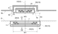
- FIG. 5 is an enlarged side view of the wireless power feeding system
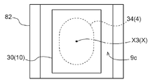
- FIG. 6 is a plan view of the power receiving side antenna coil unit 30 as viewed along the reference axis “X3” from the vehicle body bottom surface 9b side of the vehicle 9.
- the second shield plate 82 has a shape along the uneven shape of the target region including the recessed portion 9 c that is recessed above the bottom surface 9 b of the vehicle 9.
- the second shield plate 82 is disposed in the target area along the vehicle body bottom surface 9b.
- the power receiving side antenna coil unit 30 is disposed at a position overlapping the concave portion 9 c when viewed in the direction along the reference axis “X3”.
- Such a recess 9c is, for example, below the installation location of the transaxle.
- the second shield plate 82 made of a conductive material is installed in the target area including the recess 9c recessed above the bottom surface 9b of the vehicle body, it is installed on the upper side compared to the average position of the bottom surface 9b of the vehicle body. Become. Therefore, it is easy to provide a gap between the power receiving side antenna coil unit 30 installed at the bottom of the vehicle 9 and the second shield plate 82. That is, a gap of a distance “K” can be secured between the second shield plate 82 and the first shield plate 81 of the power receiving side antenna coil unit 30.
- This “K” is preferably about 5 to 10 [cm] as an example.
- the disturbing current as described above is generated in the second shield plate 82. Can be suppressed. As a result, a decrease in power transmission efficiency can also be suppressed.
- the second shield plate 82 having a sufficient size in consideration of the displacement of the relative position with the antenna coil on the power feeding side is attached to the vehicle 9. Can do. As a result, it is possible to effectively shield electromagnetic waves leaking to the vehicle body while suppressing a decrease in power transmission efficiency.
- the magnetic flux that generates the disturbing current in the second shield plate 82 is a magnetic flux interlinked with the power reception side resonance coil 34 (power reception side antenna coil). Therefore, it is preferable if the power receiving side resonance coil 34 can be installed in the range of the concave portion 9c in which a gap is easily provided between the power receiving side antenna coil unit 30 including the coil. Specifically, as shown in FIG. 6, it is preferable that the concave portion 9 c is larger than the outer shape of the power reception side resonance coil 34 when viewed in the direction along the reference axis “X3”. Alternatively, it is preferable that the outer shape of the power receiving resonance coil 34 is smaller than the recess 9c when viewed in the direction along the reference axis “X3”.
- the first shield plate 81 is provided so as to suppress the magnetic flux interlinking with the power receiving side resonance coil 34 from affecting the vehicle 9 side.
- the amount of interference current generated in the second shield plate 82 decreases as the distance between the first shield plate 81 and the second shield plate 82 increases. Therefore, it is preferable if the power receiving side antenna coil unit 30 can be installed in the range of the concave portion 9c where a gap is easily provided between the second shield plate 82 and the power receiving side antenna coil unit 30 including the first shield plate 81.
- the concave portion 9 c is larger than the outer shape of the power receiving side antenna coil unit 30 when viewed in the direction along the reference axis “X3”.
- the second shield plate 82 has a reference axis.
- the outer diameter of the power supply side resonance coil 24 (power supply side antenna coil) is larger.
- the second shield plate 82 may be larger than the outer diameter of the power feeding side antenna coil unit 20 when viewed in the direction along the reference axis X (X2).
- the laying range “W3” of the second shield plate 82 is larger than the outer diameter width “W1” of the power supply side resonance coil 24 (power supply side antenna coil).
- the power receiving side antenna coil unit 30 is provided at the bottom of the vehicle 9, it is preferable that the power receiving side antenna coil unit 30 is attached so as to reduce contact with an obstacle on the ground. In other words, it is preferable that the minimum ground clearance set for the vehicle 9 can be ensured even when the power receiving side antenna coil unit is attached to the vehicle.
- the power-receiving-side antenna coil unit 30 is arranged such that the lowest position when attached to the vehicle 9 is higher than the lowest part of the bottom of the vehicle 9. It is preferable that it is attached to.
- the height from the ground G to the lowest position in the power receiving side antenna coil unit 30 is set to “H3” (after the unit is installed). Minimum ground clearance). It is preferable that the power receiving side antenna coil unit 30 is attached to the vehicle 9 so that the lowest ground height H3 after the unit installation is higher than the height of the lowest portion of the bottom of the vehicle 9 (minimum ground height). .
- the power receiving side antenna coil unit 30 may not be attached to the vehicle 9 so that the minimum ground height H3 after the unit installation is higher than the minimum ground height of the vehicle 9.
- “minimum ground clearance H3 after unit installation” is the same as “minimum ground clearance”.
- the power-receiving-side antenna coil unit 30 is lower than the minimum ground clearance due to the relationship between the approach angle and the departure angle and the minimum ground clearance, and the position at which the obstacle easily touches the obstacle when getting over the obstacle. If there are few problems even when installed at the position, “the lowest ground height H3 after unit installation” may be lower than “the lowest ground height”.
- the wireless power feeding system 1 power transmission system
- electromagnetic resonance coupling magnetic field resonance
- the transmission method is not limited to this method, and may be an electromagnetic induction method, for example.
- the recess 9c when viewed in the direction along the reference axis “X3”, the recess 9c is larger than the outer shape of the power reception side resonance coil 34 (power reception side antenna coil) or the outer shape of the power reception side antenna coil unit 30.
- the larger form was illustrated.
- the present invention is not limited to these forms. For example, even when the concave portion 9c is smaller than these outer diameters and a gap is partially formed between the first shield plate 81 and the second shield plate 82, the amount of generated disturbing current is reduced. I can.
- the present invention can be used in a power receiving system that receives power supplied wirelessly to a power receiving circuit provided at the bottom of a vehicle.
- Power receiving system 9 Vehicle 9b: Vehicle bottom 9c: Recess 30: Power receiving side antenna coil unit 34: Power receiving side resonance coil (power receiving side antenna coil) 35: Receiving side resonance circuit (power receiving circuit) 40: conductor wire 41: coil 81: first shield plate 82: second shield plate D1: transmission direction D2: non-transmission direction X: reference axis X3: reference axis (reference axis in the power receiving side antenna coil)
Landscapes
- Engineering & Computer Science (AREA)
- Power Engineering (AREA)
- Transportation (AREA)
- Mechanical Engineering (AREA)
- Computer Networks & Wireless Communication (AREA)
- Sustainable Energy (AREA)
- Sustainable Development (AREA)
- Life Sciences & Earth Sciences (AREA)
- Physics & Mathematics (AREA)
- Electromagnetism (AREA)
- Electric Propulsion And Braking For Vehicles (AREA)
- Current-Collector Devices For Electrically Propelled Vehicles (AREA)
- Charge And Discharge Circuits For Batteries Or The Like (AREA)
Abstract
La présente invention supprime la détérioration du rendement de transmission d'énergie, et supprime la fuite d'ondes électromagnétiques vers la carrosserie d'un véhicule. Un système de réception d'énergie selon l'invention reçoit de l'énergie qui doit être fournie, d'une manière sans fil par le biais d'un champ magnétique, à un circuit de réception d'énergie dans une section inférieure d'un véhicule (9). Le système de réception d'énergie est pourvu : d'une unité à bobine d'antenne côté réception d'énergie (30), qui est pourvue d'une bobine d'antenne côté réception d'énergie (34), et d'une première plaque de blindage (81), qui est disposée du côté dans le sens inverse de transmission (D2) et qui est faite d'un matériau magnétique ; et d'une seconde plaque de blindage (82), qui a une forme épousant une forme renfoncée et saillante d'une région cible d'une surface inférieure de carrosserie (9b) du véhicule (9), ladite région cible comprenant une section renfoncée (9c), et qui est disposée dans la région cible et est faite d'un matériau conducteur. L'unité à bobine d'antenne côté réception d'énergie (30) est disposée en une position chevauchant la section renfoncée (9c), vue dans la direction d'un axe de référence (X3).
Priority Applications (2)
| Application Number | Priority Date | Filing Date | Title |
|---|---|---|---|
| DE112015001390.3T DE112015001390T5 (de) | 2014-03-26 | 2015-03-23 | Leistungsempfangssystem |
| US15/118,284 US20160355094A1 (en) | 2014-03-26 | 2015-03-23 | Power receiving system |
Applications Claiming Priority (2)
| Application Number | Priority Date | Filing Date | Title |
|---|---|---|---|
| JP2014063813A JP2015186426A (ja) | 2014-03-26 | 2014-03-26 | 受電システム |
| JP2014-063813 | 2014-03-26 |
Publications (1)
| Publication Number | Publication Date |
|---|---|
| WO2015146889A1 true WO2015146889A1 (fr) | 2015-10-01 |
Family
ID=54195402
Family Applications (1)
| Application Number | Title | Priority Date | Filing Date |
|---|---|---|---|
| PCT/JP2015/058688 Ceased WO2015146889A1 (fr) | 2014-03-26 | 2015-03-23 | Système de réception d'énergie |
Country Status (4)
| Country | Link |
|---|---|
| US (1) | US20160355094A1 (fr) |
| JP (1) | JP2015186426A (fr) |
| DE (1) | DE112015001390T5 (fr) |
| WO (1) | WO2015146889A1 (fr) |
Cited By (1)
| Publication number | Priority date | Publication date | Assignee | Title |
|---|---|---|---|---|
| CN111048298A (zh) * | 2018-10-11 | 2020-04-21 | 丰田合成株式会社 | 输电线圈及无线供电装置 |
Families Citing this family (16)
| Publication number | Priority date | Publication date | Assignee | Title |
|---|---|---|---|---|
| GB2501482A (en) * | 2012-04-23 | 2013-10-30 | Bombardier Transp Gmbh | Providing a land vehicle with electric energy by magnetic induction |
| WO2017159330A1 (fr) * | 2016-03-18 | 2017-09-21 | 株式会社村田製作所 | Dispositif de transmission d'énergie, dispositif de réception d'énergie et système d'alimentation en énergie sans fil |
| DE102016205352A1 (de) * | 2016-03-31 | 2017-10-05 | Bayerische Motoren Werke Aktiengesellschaft | Primärspuleneinheit |
| US10457147B2 (en) * | 2016-05-20 | 2019-10-29 | Ford Global Technologies, Llc | Controlling operation of electrified vehicles traveling on inductive roadway to influence electrical grid |
| KR102034403B1 (ko) * | 2016-05-25 | 2019-10-18 | 닛산 지도우샤 가부시키가이샤 | 비접촉 수전 장치 |
| JP6496288B2 (ja) * | 2016-09-13 | 2019-04-03 | 本田技研工業株式会社 | 車両用充電部配置構造 |
| JP6480976B2 (ja) | 2017-04-11 | 2019-03-13 | 株式会社Subaru | 非接触受電装置 |
| JP7003651B2 (ja) * | 2017-12-27 | 2022-01-20 | トヨタ自動車株式会社 | 車両 |
| JP2019198181A (ja) * | 2018-05-10 | 2019-11-14 | Nittoku株式会社 | 回転テーブル式製造装置 |
| JP7165047B2 (ja) * | 2018-12-21 | 2022-11-02 | 株式会社Subaru | 電動車両 |
| JP7272051B2 (ja) * | 2019-03-28 | 2023-05-12 | 株式会社豊田中央研究所 | 送電装置、受電装置および非接触給電システム |
| JP7462896B2 (ja) * | 2019-10-09 | 2024-04-08 | 国立大学法人 東京大学 | 無線受電システム、移動体、及び車輪 |
| CN116724369A (zh) * | 2020-12-09 | 2023-09-08 | 松下知识产权经营株式会社 | 无线供电单元和无线电力传输系统 |
| CN116455102B (zh) * | 2022-02-28 | 2024-04-05 | 荣耀终端有限公司 | 充电线圈组件和无线充电装置 |
| US12606035B2 (en) * | 2022-12-06 | 2026-04-21 | Volkswagen Aktiengesellschaft | Devices, systems, and methods for wireless vehicle charging |
| JP7794111B2 (ja) * | 2022-12-07 | 2026-01-06 | トヨタ自動車株式会社 | 受電装置及び非接触給電システム |
Citations (2)
| Publication number | Priority date | Publication date | Assignee | Title |
|---|---|---|---|---|
| JP2012228149A (ja) * | 2011-04-22 | 2012-11-15 | Yazaki Corp | 共鳴式非接触給電システム |
| JP2013146148A (ja) * | 2012-01-16 | 2013-07-25 | Toyota Motor Corp | 車両 |
Family Cites Families (13)
| Publication number | Priority date | Publication date | Assignee | Title |
|---|---|---|---|---|
| JP4453741B2 (ja) * | 2007-10-25 | 2010-04-21 | トヨタ自動車株式会社 | 電動車両および車両用給電装置 |
| JP4743244B2 (ja) * | 2008-09-18 | 2011-08-10 | トヨタ自動車株式会社 | 非接触受電装置 |
| JP2010178499A (ja) * | 2009-01-29 | 2010-08-12 | Aisin Aw Co Ltd | 無接点充電装置、その無接点充電装置用の位置関係検出装置の測距装置、及び、位置関係検出装置の被測距装置 |
| JP5746049B2 (ja) * | 2009-12-17 | 2015-07-08 | トヨタ自動車株式会社 | 受電装置および送電装置 |
| JP5077340B2 (ja) * | 2009-12-25 | 2012-11-21 | トヨタ自動車株式会社 | 非接触受電装置およびその製造方法 |
| JP5759716B2 (ja) * | 2010-12-22 | 2015-08-05 | 富士通テン株式会社 | 無線電力伝送システム |
| JP2012178529A (ja) * | 2011-02-28 | 2012-09-13 | Equos Research Co Ltd | アンテナ |
| JP5740200B2 (ja) * | 2011-04-22 | 2015-06-24 | 矢崎総業株式会社 | 共鳴式非接触給電システム、受電側装置及び送電側装置 |
| WO2013042229A1 (fr) * | 2011-09-21 | 2013-03-28 | トヨタ自動車株式会社 | Dispositif de transmission de puissance sans contact, dispositif de réception de puissance sans contact et système émetteur-récepteur de puissance sans contact |
| JP2013143846A (ja) * | 2012-01-11 | 2013-07-22 | Kojima Press Industry Co Ltd | 車両用非接触充電システムに用いられる送受電コイルおよび送受波装置 |
| JP2013211933A (ja) * | 2012-03-30 | 2013-10-10 | Equos Research Co Ltd | 電力伝送システム |
| JP2013255349A (ja) * | 2012-06-07 | 2013-12-19 | Equos Research Co Ltd | アンテナ |
| JP2013254851A (ja) * | 2012-06-07 | 2013-12-19 | Equos Research Co Ltd | アンテナ |
-
2014
- 2014-03-26 JP JP2014063813A patent/JP2015186426A/ja active Pending
-
2015
- 2015-03-23 WO PCT/JP2015/058688 patent/WO2015146889A1/fr not_active Ceased
- 2015-03-23 US US15/118,284 patent/US20160355094A1/en not_active Abandoned
- 2015-03-23 DE DE112015001390.3T patent/DE112015001390T5/de not_active Withdrawn
Patent Citations (2)
| Publication number | Priority date | Publication date | Assignee | Title |
|---|---|---|---|---|
| JP2012228149A (ja) * | 2011-04-22 | 2012-11-15 | Yazaki Corp | 共鳴式非接触給電システム |
| JP2013146148A (ja) * | 2012-01-16 | 2013-07-25 | Toyota Motor Corp | 車両 |
Cited By (2)
| Publication number | Priority date | Publication date | Assignee | Title |
|---|---|---|---|---|
| CN111048298A (zh) * | 2018-10-11 | 2020-04-21 | 丰田合成株式会社 | 输电线圈及无线供电装置 |
| CN111048298B (zh) * | 2018-10-11 | 2021-12-24 | 丰田合成株式会社 | 输电线圈及无线供电装置 |
Also Published As
| Publication number | Publication date |
|---|---|
| JP2015186426A (ja) | 2015-10-22 |
| US20160355094A1 (en) | 2016-12-08 |
| DE112015001390T5 (de) | 2017-01-26 |
Similar Documents
| Publication | Publication Date | Title |
|---|---|---|
| WO2015146889A1 (fr) | Système de réception d'énergie | |
| JP5810944B2 (ja) | 車両および電力伝送システム | |
| US10202045B2 (en) | Vehicle with shielded power receiving coil | |
| JP6142413B2 (ja) | アンテナコイルユニット | |
| JP6091262B2 (ja) | 給電部、受電部及び給電システム | |
| JP5776703B2 (ja) | 車両および外部給電装置 | |
| JP5668676B2 (ja) | 受電装置およびそれを備える車両、送電装置、ならびに電力伝送システム | |
| JP5690642B2 (ja) | 共鳴式非接触給電システム、共鳴式非接触給電システムの送電側装置及び車載充電装置 | |
| KR101750149B1 (ko) | 차량 | |
| US9917478B2 (en) | Power transmission device, power reception device and power transfer system | |
| JP2015015852A (ja) | コイルアンテナ | |
| CN104303363A (zh) | 天线线圈 | |
| JP6028000B2 (ja) | 電力伝送システム | |
| JP2014179438A (ja) | コイルユニット及び非接触給電装置 | |
| CN104093592A (zh) | 电力发送装置、电力接收装置和电力传输系统 | |
| CN104242480A (zh) | 电磁波泄露防护设备 | |
| JP2013207727A (ja) | アンテナコイル | |
| JP6232191B2 (ja) | 給電部、受電部及び給電システム | |
| JP2015089259A (ja) | アンテナコイルユニット | |
| JP2014197932A (ja) | 電力伝送システム | |
| JP2017107896A (ja) | 非接触給電システム | |
| JP2015065341A (ja) | アンテナコイル及び電力伝送システム | |
| JP2014050302A (ja) | 非接触給電装置 |
Legal Events
| Date | Code | Title | Description |
|---|---|---|---|
| 121 | Ep: the epo has been informed by wipo that ep was designated in this application |
Ref document number: 15769229 Country of ref document: EP Kind code of ref document: A1 |
|
| WWE | Wipo information: entry into national phase |
Ref document number: 15118284 Country of ref document: US |
|
| WWE | Wipo information: entry into national phase |
Ref document number: 112015001390 Country of ref document: DE |
|
| 122 | Ep: pct application non-entry in european phase |
Ref document number: 15769229 Country of ref document: EP Kind code of ref document: A1 |