WO2015146913A1 - 燃焼排ガス浄化用触媒、および燃焼排ガスの浄化方法 - Google Patents
燃焼排ガス浄化用触媒、および燃焼排ガスの浄化方法 Download PDFInfo
- Publication number
- WO2015146913A1 WO2015146913A1 PCT/JP2015/058742 JP2015058742W WO2015146913A1 WO 2015146913 A1 WO2015146913 A1 WO 2015146913A1 JP 2015058742 W JP2015058742 W JP 2015058742W WO 2015146913 A1 WO2015146913 A1 WO 2015146913A1
- Authority
- WO
- WIPO (PCT)
- Prior art keywords
- exhaust gas
- catalyst
- combustion exhaust
- diffraction
- reducing agent
- Prior art date
- Legal status (The legal status is an assumption and is not a legal conclusion. Google has not performed a legal analysis and makes no representation as to the accuracy of the status listed.)
- Ceased
Links
Images


Classifications
-
- B—PERFORMING OPERATIONS; TRANSPORTING
- B01—PHYSICAL OR CHEMICAL PROCESSES OR APPARATUS IN GENERAL
- B01J—CHEMICAL OR PHYSICAL PROCESSES, e.g. CATALYSIS OR COLLOID CHEMISTRY; THEIR RELEVANT APPARATUS
- B01J29/00—Catalysts comprising molecular sieves
- B01J29/04—Catalysts comprising molecular sieves having base-exchange properties, e.g. crystalline zeolites
- B01J29/06—Crystalline aluminosilicate zeolites; Isomorphous compounds thereof
- B01J29/064—Crystalline aluminosilicate zeolites; Isomorphous compounds thereof containing iron group metals, noble metals or copper
- B01J29/072—Iron group metals or copper
-
- B—PERFORMING OPERATIONS; TRANSPORTING
- B01—PHYSICAL OR CHEMICAL PROCESSES OR APPARATUS IN GENERAL
- B01D—SEPARATION
- B01D53/00—Separation of gases or vapours; Recovering vapours of volatile solvents from gases; Chemical or biological purification of waste gases, e.g. engine exhaust gases, smoke, fumes, flue gases, aerosols
- B01D53/34—Chemical or biological purification of waste gases
- B01D53/92—Chemical or biological purification of waste gases of engine exhaust gases
- B01D53/94—Chemical or biological purification of waste gases of engine exhaust gases by catalytic processes
- B01D53/9404—Removing only nitrogen compounds
- B01D53/9409—Nitrogen oxides
- B01D53/9413—Processes characterised by a specific catalyst
- B01D53/9418—Processes characterised by a specific catalyst for removing nitrogen oxides by selective catalytic reduction [SCR] using a reducing agent in a lean exhaust gas
-
- B—PERFORMING OPERATIONS; TRANSPORTING
- B01—PHYSICAL OR CHEMICAL PROCESSES OR APPARATUS IN GENERAL
- B01J—CHEMICAL OR PHYSICAL PROCESSES, e.g. CATALYSIS OR COLLOID CHEMISTRY; THEIR RELEVANT APPARATUS
- B01J23/00—Catalysts comprising metals or metal oxides or hydroxides, not provided for in group B01J21/00
- B01J23/70—Catalysts comprising metals or metal oxides or hydroxides, not provided for in group B01J21/00 of the iron group metals or copper
- B01J23/74—Iron group metals
- B01J23/75—Cobalt
-
- B—PERFORMING OPERATIONS; TRANSPORTING
- B01—PHYSICAL OR CHEMICAL PROCESSES OR APPARATUS IN GENERAL
- B01J—CHEMICAL OR PHYSICAL PROCESSES, e.g. CATALYSIS OR COLLOID CHEMISTRY; THEIR RELEVANT APPARATUS
- B01J29/00—Catalysts comprising molecular sieves
- B01J29/04—Catalysts comprising molecular sieves having base-exchange properties, e.g. crystalline zeolites
- B01J29/06—Crystalline aluminosilicate zeolites; Isomorphous compounds thereof
- B01J29/40—Crystalline aluminosilicate zeolites; Isomorphous compounds thereof of the pentasil type, e.g. types ZSM-5, ZSM-8 or ZSM-11, as exemplified by patent documents US3702886, GB1334243 and US3709979, respectively
- B01J29/42—Crystalline aluminosilicate zeolites; Isomorphous compounds thereof of the pentasil type, e.g. types ZSM-5, ZSM-8 or ZSM-11, as exemplified by patent documents US3702886, GB1334243 and US3709979, respectively containing iron group metals, noble metals or copper
- B01J29/46—Iron group metals or copper
-
- B—PERFORMING OPERATIONS; TRANSPORTING
- B01—PHYSICAL OR CHEMICAL PROCESSES OR APPARATUS IN GENERAL
- B01J—CHEMICAL OR PHYSICAL PROCESSES, e.g. CATALYSIS OR COLLOID CHEMISTRY; THEIR RELEVANT APPARATUS
- B01J29/00—Catalysts comprising molecular sieves
- B01J29/04—Catalysts comprising molecular sieves having base-exchange properties, e.g. crystalline zeolites
- B01J29/06—Crystalline aluminosilicate zeolites; Isomorphous compounds thereof
- B01J29/65—Crystalline aluminosilicate zeolites; Isomorphous compounds thereof of the ferrierite type, e.g. types ZSM-21, ZSM-35 or ZSM-38, as exemplified by patent documents US4046859, US4016245 and US4046859, respectively
- B01J29/66—Crystalline aluminosilicate zeolites; Isomorphous compounds thereof of the ferrierite type, e.g. types ZSM-21, ZSM-35 or ZSM-38, as exemplified by patent documents US4046859, US4016245 and US4046859, respectively containing iron group metals, noble metals or copper
- B01J29/68—Iron group metals or copper
-
- B—PERFORMING OPERATIONS; TRANSPORTING
- B01—PHYSICAL OR CHEMICAL PROCESSES OR APPARATUS IN GENERAL
- B01J—CHEMICAL OR PHYSICAL PROCESSES, e.g. CATALYSIS OR COLLOID CHEMISTRY; THEIR RELEVANT APPARATUS
- B01J35/00—Catalysts, in general, characterised by their form or physical properties
- B01J35/19—Catalysts containing parts with different compositions
-
- B—PERFORMING OPERATIONS; TRANSPORTING
- B01—PHYSICAL OR CHEMICAL PROCESSES OR APPARATUS IN GENERAL
- B01J—CHEMICAL OR PHYSICAL PROCESSES, e.g. CATALYSIS OR COLLOID CHEMISTRY; THEIR RELEVANT APPARATUS
- B01J37/00—Processes, in general, for preparing catalysts; Processes, in general, for activation of catalysts
- B01J37/0009—Use of binding agents; Moulding; Pressing; Powdering; Granulating; Addition of materials ameliorating the mechanical properties of the product catalyst
- B01J37/0018—Addition of a binding agent or of material, later completely removed among others as result of heat treatment, leaching or washing,(e.g. forming of pores; protective layer, desintegrating by heat)
-
- B—PERFORMING OPERATIONS; TRANSPORTING
- B01—PHYSICAL OR CHEMICAL PROCESSES OR APPARATUS IN GENERAL
- B01J—CHEMICAL OR PHYSICAL PROCESSES, e.g. CATALYSIS OR COLLOID CHEMISTRY; THEIR RELEVANT APPARATUS
- B01J37/00—Processes, in general, for preparing catalysts; Processes, in general, for activation of catalysts
- B01J37/02—Impregnation, coating or precipitation
- B01J37/0201—Impregnation
-
- B—PERFORMING OPERATIONS; TRANSPORTING
- B01—PHYSICAL OR CHEMICAL PROCESSES OR APPARATUS IN GENERAL
- B01J—CHEMICAL OR PHYSICAL PROCESSES, e.g. CATALYSIS OR COLLOID CHEMISTRY; THEIR RELEVANT APPARATUS
- B01J37/00—Processes, in general, for preparing catalysts; Processes, in general, for activation of catalysts
- B01J37/16—Reducing
-
- F—MECHANICAL ENGINEERING; LIGHTING; HEATING; WEAPONS; BLASTING
- F01—MACHINES OR ENGINES IN GENERAL; ENGINE PLANTS IN GENERAL; STEAM ENGINES
- F01N—GAS-FLOW SILENCERS OR EXHAUST APPARATUS FOR MACHINES OR ENGINES IN GENERAL; GAS-FLOW SILENCERS OR EXHAUST APPARATUS FOR INTERNAL-COMBUSTION ENGINES
- F01N3/00—Exhaust or silencing apparatus having means for purifying, rendering innocuous, or otherwise treating exhaust
- F01N3/08—Exhaust or silencing apparatus having means for purifying, rendering innocuous, or otherwise treating exhaust for rendering innocuous
- F01N3/10—Exhaust or silencing apparatus having means for purifying, rendering innocuous, or otherwise treating exhaust for rendering innocuous by thermal or catalytic conversion of noxious components of exhaust
- F01N3/18—Exhaust or silencing apparatus having means for purifying, rendering innocuous, or otherwise treating exhaust for rendering innocuous by thermal or catalytic conversion of noxious components of exhaust characterised by methods of operation; Control
- F01N3/20—Exhaust or silencing apparatus having means for purifying, rendering innocuous, or otherwise treating exhaust for rendering innocuous by thermal or catalytic conversion of noxious components of exhaust characterised by methods of operation; Control specially adapted for catalytic conversion
-
- B—PERFORMING OPERATIONS; TRANSPORTING
- B01—PHYSICAL OR CHEMICAL PROCESSES OR APPARATUS IN GENERAL
- B01D—SEPARATION
- B01D2251/00—Reactants
- B01D2251/20—Reductants
- B01D2251/208—Hydrocarbons
-
- B—PERFORMING OPERATIONS; TRANSPORTING
- B01—PHYSICAL OR CHEMICAL PROCESSES OR APPARATUS IN GENERAL
- B01D—SEPARATION
- B01D2255/00—Catalysts
- B01D2255/20—Metals or compounds thereof
- B01D2255/207—Transition metals
- B01D2255/20746—Cobalt
-
- B—PERFORMING OPERATIONS; TRANSPORTING
- B01—PHYSICAL OR CHEMICAL PROCESSES OR APPARATUS IN GENERAL
- B01D—SEPARATION
- B01D2255/00—Catalysts
- B01D2255/50—Zeolites
-
- B—PERFORMING OPERATIONS; TRANSPORTING
- B01—PHYSICAL OR CHEMICAL PROCESSES OR APPARATUS IN GENERAL
- B01D—SEPARATION
- B01D2255/00—Catalysts
- B01D2255/50—Zeolites
- B01D2255/504—ZSM 5 zeolites
-
- B—PERFORMING OPERATIONS; TRANSPORTING
- B01—PHYSICAL OR CHEMICAL PROCESSES OR APPARATUS IN GENERAL
- B01J—CHEMICAL OR PHYSICAL PROCESSES, e.g. CATALYSIS OR COLLOID CHEMISTRY; THEIR RELEVANT APPARATUS
- B01J2229/00—Aspects of molecular sieve catalysts not covered by B01J29/00
- B01J2229/10—After treatment, characterised by the effect to be obtained
- B01J2229/18—After treatment, characterised by the effect to be obtained to introduce other elements into or onto the molecular sieve itself
- B01J2229/186—After treatment, characterised by the effect to be obtained to introduce other elements into or onto the molecular sieve itself not in framework positions
-
- B—PERFORMING OPERATIONS; TRANSPORTING
- B01—PHYSICAL OR CHEMICAL PROCESSES OR APPARATUS IN GENERAL
- B01J—CHEMICAL OR PHYSICAL PROCESSES, e.g. CATALYSIS OR COLLOID CHEMISTRY; THEIR RELEVANT APPARATUS
- B01J2229/00—Aspects of molecular sieve catalysts not covered by B01J29/00
- B01J2229/30—After treatment, characterised by the means used
- B01J2229/40—Special temperature treatment, i.e. other than just for template removal
-
- B—PERFORMING OPERATIONS; TRANSPORTING
- B01—PHYSICAL OR CHEMICAL PROCESSES OR APPARATUS IN GENERAL
- B01J—CHEMICAL OR PHYSICAL PROCESSES, e.g. CATALYSIS OR COLLOID CHEMISTRY; THEIR RELEVANT APPARATUS
- B01J2235/00—Indexing scheme associated with group B01J35/00, related to the analysis techniques used to determine the catalysts form or properties
- B01J2235/15—X-ray diffraction
-
- B—PERFORMING OPERATIONS; TRANSPORTING
- B01—PHYSICAL OR CHEMICAL PROCESSES OR APPARATUS IN GENERAL
- B01J—CHEMICAL OR PHYSICAL PROCESSES, e.g. CATALYSIS OR COLLOID CHEMISTRY; THEIR RELEVANT APPARATUS
- B01J37/00—Processes, in general, for preparing catalysts; Processes, in general, for activation of catalysts
- B01J37/02—Impregnation, coating or precipitation
- B01J37/024—Multiple impregnation or coating
- B01J37/0246—Coatings comprising a zeolite
-
- F—MECHANICAL ENGINEERING; LIGHTING; HEATING; WEAPONS; BLASTING
- F01—MACHINES OR ENGINES IN GENERAL; ENGINE PLANTS IN GENERAL; STEAM ENGINES
- F01N—GAS-FLOW SILENCERS OR EXHAUST APPARATUS FOR MACHINES OR ENGINES IN GENERAL; GAS-FLOW SILENCERS OR EXHAUST APPARATUS FOR INTERNAL-COMBUSTION ENGINES
- F01N2370/00—Selection of materials for exhaust purification
- F01N2370/02—Selection of materials for exhaust purification used in catalytic reactors
- F01N2370/04—Zeolitic material
-
- F—MECHANICAL ENGINEERING; LIGHTING; HEATING; WEAPONS; BLASTING
- F01—MACHINES OR ENGINES IN GENERAL; ENGINE PLANTS IN GENERAL; STEAM ENGINES
- F01N—GAS-FLOW SILENCERS OR EXHAUST APPARATUS FOR MACHINES OR ENGINES IN GENERAL; GAS-FLOW SILENCERS OR EXHAUST APPARATUS FOR INTERNAL-COMBUSTION ENGINES
- F01N2570/00—Exhaust treating apparatus eliminating, absorbing or adsorbing specific elements or compounds
- F01N2570/14—Nitrogen oxides
-
- Y—GENERAL TAGGING OF NEW TECHNOLOGICAL DEVELOPMENTS; GENERAL TAGGING OF CROSS-SECTIONAL TECHNOLOGIES SPANNING OVER SEVERAL SECTIONS OF THE IPC; TECHNICAL SUBJECTS COVERED BY FORMER USPC CROSS-REFERENCE ART COLLECTIONS [XRACs] AND DIGESTS
- Y02—TECHNOLOGIES OR APPLICATIONS FOR MITIGATION OR ADAPTATION AGAINST CLIMATE CHANGE
- Y02T—CLIMATE CHANGE MITIGATION TECHNOLOGIES RELATED TO TRANSPORTATION
- Y02T10/00—Road transport of goods or passengers
- Y02T10/10—Internal combustion engine [ICE] based vehicles
- Y02T10/12—Improving ICE efficiencies
Definitions
- the present invention relates to, for example, a catalyst for purifying a flue gas for removing nitrogen oxides (NOx) in flue gas discharged from an internal combustion engine such as a diesel engine for ships, and a method for purifying a flue gas.
- a catalyst for purifying a flue gas for removing nitrogen oxides (NOx) in flue gas discharged from an internal combustion engine such as a diesel engine for ships and a method for purifying a flue gas.
- ammonia selective reduction method In the case of removing nitrogen oxides in the combustion exhaust gas of an internal combustion engine such as a marine diesel engine, the ammonia selective reduction method is the mainstream as the method.
- This ammonia selective reduction method is a method using ammonia as a reducing agent, using a denitration catalyst mainly composed of vanadium and titania.
- ammonium sulfate sulfur oxide in the exhaust gas reacts with ammonia which is a reducing agent
- ammonium sulfate is deposited in the exhaust passage and the heat exchanger is clogged.
- Patent Document 1 describes a method using an alcohol as a reducing agent in a catalyst in which a metal is supported on zeolite.
- a NOx removal catalyst layer is disposed in the exhaust gas processing channel branched into two systems, one exhaust gas processing channel is closed to stop the supply of exhaust gas, and the other exhaust gas processing channel It is disclosed that the reduced NOx removal performance is recovered by heat treating the NOx removal catalyst layer of the exhaust gas processing flow path whose exhaust gas supply is stopped at 350 to 800 ° C. in situ while continuing the exhaust gas processing.
- JP 2004-358454 A Japanese Patent Application Laid-Open No. 2006-220107
- Patent Document 2 when the amount of the reducing agent is large, carbons and the like are deposited on the catalyst with the passage of time, and there is a problem that the NOx removal performance is lowered.
- the object of the present invention is to solve the above-mentioned problems of the prior art, and to remove nitrogen oxides in the relatively low temperature exhaust gas emitted from an internal combustion engine such as a marine diesel engine
- an internal combustion engine such as a marine diesel engine
- the present inventors have physical properties with a predetermined relative peak intensity ratio in X-ray diffraction (XRD) analysis as a zeolite carrier used for a catalyst for purification of combustion exhaust gas.
- XRD X-ray diffraction
- the invention according to claim 1 is a NOx removal catalyst used in a purification method of combustion exhaust gas, which is brought into contact with combustion exhaust gas added with alcohol as a reducing agent to remove nitrogen oxides in the exhaust gas.
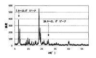
- the catalyst has been supported on zeolite, which is a carrier, and the denitration catalyst has a diffraction angle (2 ⁇ ) of 7.8 to 10 in powder X-ray diffraction (XRD) measurement of the denitration catalyst.
- the invention according to claim 2 is the catalyst for purification of combustion exhaust gas according to claim 1, characterized in that the zeolite as the carrier is made of zeolite which has been calcined in advance in an inert gas atmosphere.
- the invention of claim 3 is the catalyst for purification of combustion exhaust gas according to claim 1, characterized in that the catalyst metal is cobalt (Co).
- the invention of claim 4 is the catalyst for purification of combustion exhaust gas according to claim 2, characterized in that the catalyst metal is cobalt (Co).
- the invention according to claim 5 is the catalyst for purification of combustion exhaust gas according to any one of claims 1 to 4, characterized in that the alcohol as the reducing agent is methanol or ethanol.
- the invention according to claim 6 is a method for purifying combustion exhaust gas, wherein a catalyst metal is supported on a carrier consisting of zeolite previously calcined in an inert gas atmosphere and the diffraction angle (2 ⁇ ) in powder X-ray diffraction (XRD) measurement.
- Ratio (relative peak intensity ratio) r of the diffraction peak height I of 7.8 to 10.0 ° and the diffraction peak height J of the same diffraction angle (2 ⁇ ) of 28.0 to 31.0 ° It is characterized in that nitrogen oxides in exhaust gas are removed by bringing a combustion exhaust gas added with alcohol as a reducing agent into contact with a denitration catalyst in which / J is in the range of 3.0 to 5.0.
- the selectivity of the alcohol reducing agent to the denitrification reaction is improved more than before in removing nitrogen oxides in the exhaust gas in a relatively low temperature range emitted from an internal combustion engine such as a marine diesel engine. Even if the amount of the reducing agent is the same as the conventional one, the denitration performance is improved, and the effect that the exhaust gas treatment with higher efficiency can be performed is exhibited.
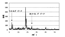
- FIG. 7 is a powder X-ray diffraction (XRD) chart of the NOx removal catalyst obtained in Comparative Example 1.
- FIG. 7 is a powder X-ray diffraction (XRD) chart of the NOx removal catalyst obtained in Comparative Example 2.
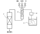
- FIG. It is a flowchart which shows an example of the NOx removal rate measuring apparatus used for a catalyst performance test in the Example of this invention.
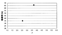
- FIG. 6 is a graph showing the relationship between the relative peak intensity ratio r and the NOx removal rate for a NOx removal catalyst in which cobalt (Co) is supported on MFI (ZSM-5) type zeolite. It is a graph which shows the relative peak intensity ratio r about the denitration catalyst which made the ferrierite (FER) type
- FER ferrierite
- the catalyst for purification of combustion exhaust gas according to the present invention is used, for example, to remove nitrogen oxides (NOx) in combustion exhaust gas emitted from internal combustion engines such as diesel engines, oil-fired boilers and gas turbines.
- NOx nitrogen oxides
- the zeolite is not particularly limited as long as it can exhibit the NOx removal performance, but when a zeolite having a strong acid strength is used like MOR type zeolite, a large amount of reducing agent is required. Also, in order to exert denitration performance even in a low temperature range around 200 ° C., a zeolite with weak acid strength such as ⁇ -type zeolite or Y-type zeolite is less likely to react with the reducing agent, so it is relatively more than MOR type. It is preferable to use MFI-type zeolite or FER-type zeolite, which has a weak acid strength and a stronger acid strength than ⁇ -type zeolite or Y-type zeolite.
- the zeolite as the carrier is preferably made of zeolite which has been calcined in advance under an inert gas atmosphere such as nitrogen.
- a predetermined catalyst metal is added to the zeolite in the presence of alcohol which is a reducing agent.
- alcohol which is a reducing agent.
- the diffraction peak height I of diffraction angle (2 ⁇ ) 7.8 to 10.0 ° and the diffraction angle (2 ⁇ )
- the acid point on the surface of the denitrification catalyst is appropriate It is considered that the selectivity of the alcohol reducing agent is improved and the NOx removal efficiency is improved.
- the reactivity itself it is considered that the denitrification rate decreases.
- the catalyst metal supported on the zeolite is preferably cobalt (Co).
- Co cobalt
- inorganic acid salts for example, nitrate, chloride and the like
- organic acid salts for example, acetate and the like
- the catalyst metal may be supported by any method as long as denitration performance can be exhibited, and examples thereof include ion exchange and impregnation and support.
- the ion exchange method there is a method of suspending zeolite in an aqueous solution containing a precursor compound of cobalt (Co), removing the zeolite to which a catalyst metal is bonded by ion exchange from the aqueous solution, drying it, and calcining.
- the alcohol as the reducing agent is not particularly limited as long as it has a reducing power at the temperature at the time of the reduction treatment of the exhaust gas. It is preferable to use certain methanol and ethanol.
- the shape of the catalyst for purification of combustion exhaust gas according to the present invention can be arbitrarily selected according to the reactor to be applied, such as granular, pellet, honeycomb, plate, etc., and the gas flow condition.
- a reducing agent to the flue gas at a concentration ratio of reducing agent / NOx in the flue gas of 0.1 to 4, preferably 1 to 4.
- concentration ratio of reducing agent / NOx in exhaust gas depends on the required NOx removal rate, for example, if the required NOx removal rate is 30% or less, the concentration ratio of NOx in reducing agent / exhaust gas is 0.1 It can be achieved even with 1.
- the method for purifying combustion exhaust gas of the present invention in the removal of nitrogen oxides in exhaust gas in a relatively low temperature region emitted from an internal combustion engine such as a diesel engine for ships Since the rate is improved, the denitration performance is improved even with the same amount of reducing agent as in the conventional case, and the exhaust gas treatment can be performed more efficiently.
- Example 1 Preparation of Co / MFI Zeolite Catalyst
- a catalyst in which cobalt (Co) was supported on MFI (ZSM-5) type zeolite was manufactured.
- MFI-type zeolite Tosoh HSZ-830 NHA was calcined at 650 ° C. for 12 hours under N 2 atmosphere. 10 g of the calcined zeolite was placed in 200 ml of a 0.1 mol (M) aqueous solution of cobalt nitrate (manufactured by Kishida Chemical Co., Ltd.), and immersed and stirred at a temperature of 80 ° C. for 12 hours or more to perform ion exchange. After ion exchange, the reaction solution was filtered, washed with 440 ml of ion exchange water, and dried at 100 ° C. for 12 hours to obtain a NOx removal catalyst composed of cobalt (Co) ion exchange zeolite.
- M 0.1 mol
- cobalt nitrate manufactured by Kishida Chemical Co., Ltd.
- the Co content of the NOx removal catalyst was determined by X-ray fluorescence (XRF) measurement, and the amount of Co supported was 0.5% by weight.
- Example 2 The NOx removal catalyst for purification of combustion exhaust gas of the present invention is produced in the same manner as in Example 1 above, but the difference from Example 1 is that in Example 2 the calcination conditions of commercially available MFI-type zeolite are In Example 3, the calcination conditions of commercially available MFI-type zeolite are 24 hours at 700.degree. C. In Example 4, the calcination conditions of commercially available MFI-type zeolite are 36 hours at 700.degree. C. The point is
- the Co content of the NOx removal catalysts of Examples 2 to 4 is determined, and powder X-ray diffraction (XRD) measurement of the NOx removal catalysts of Examples 2 to 4 (trade name: MultiFlex manufactured by RIGAKU CO., LTD.,
- XRD powder X-ray diffraction
- the ratio (relative peak intensity ratio) r to I / J was measured, and the obtained results are shown in Table 1 below together with the type of carrier zeolite used and the calcination conditions.
- the powder X-ray diffraction (XRD) chart of the NOx removal catalyst for purification of combustion exhaust gas obtained in Example 2 of the present invention is as shown in FIG.
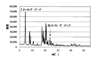
- Example 5 The NOx removal catalyst for purifying a combustion exhaust gas of the present invention is produced in the same manner as in Example 2 above, but the difference from the case in Example 2 is that the ferrierite (FER) type zeolite commercially available as zeolite (trade name) The point is that Co / FER zeolite denitration catalyst was manufactured and used using HSZ-720 NHA (manufactured by Tosoh Corporation).
- FER ferrierite
- zeolite trade name
- Co / FER zeolite denitration catalyst was manufactured and used using HSZ-720 NHA (manufactured by Tosoh Corporation).
- the ratio (relative peak intensity ratio) r I / J was measured, and the obtained results are shown in Table 1 below together with the type of carrier zeolite used and the calcination conditions.
- Example 5 of the present invention a powder X-ray diffraction (XRD) chart of the NOx removal catalyst for purification of combustion exhaust gas obtained in Example 5 of the present invention is as shown in FIG.
- Example 1 a NOx removal catalyst for purifying combustion exhaust gas is produced in the same manner as in Example 1, but the difference from Example 1 is that the commercially available MFI-type zeolite is not calcined. It is in the point of using unfired MFI-type zeolite.
- Example 2 a NOx removal catalyst for purifying combustion exhaust gas is produced in the same manner as in Example 5 above, but the difference from Example 5 is that the calcination of the commercially available ferrierite (FER) type zeolite is carried out The point is that unfired FER type zeolite is used.
- FER ferrierite
- the ratio (relative peak intensity ratio) r I / J was measured, and the obtained results are shown in Table 1 below together with the type of carrier zeolite used and the calcination conditions.
- Example 3 a NOx removal catalyst for purification of combustion exhaust gas is produced in the same manner as in Example 1 above, but the difference from Example 1 is that in Comparative Example 3, the commercially available MFI-type zeolite is used.
- the calcination conditions were set to 600 ° C. for 12 hours, and in Comparative Example 4, the calcination conditions for the commercially available MFI-type zeolite were set to 800 ° C. for 12 hours.
- FIG. 5 shows a flow chart of the performance evaluation test apparatus for the NOx removal catalyst.
- the catalyst consisting of the Co / MFI-type zeolite obtained as described above was press-molded and then crushed, and sized to a mesh size of 26 to 16 to make a pellet catalyst. This was filled in a denitrification reactor (1) consisting of a stainless steel reaction tube with an inner diameter of 10.6 mm in a test device whose flow chart is shown in FIG.
- a gas for denitration test is introduced from the upper part of the denitration reactor (1) filled with the above denitration catalyst, and the treated gas discharged from the lower part of the denitration reactor (1) is discharged to the outside Some of them are subjected to gas analysis.
- the test gas introduced into the denitrification reactor (1) is prepared by mixing air, N 2 gas, and NO / N 2 gas.
- the mixed gas is introduced into the upper end of the evaporator (2).
- An aqueous solution of alcohol as a reducing agent which is pumped up from the aqueous alcohol solution tank (4) by a metering pump (3), is supplied to a portion near the upper end of the evaporator (2).
- the alcohol aqueous solution is evaporated by heating of the heater, and is supplied to the denitrification reactor (1) from the lower part of the evaporator (2) together with the NO / N 2 mixed gas.
- the denitrified gas discharged from the denitrification reactor (1) after the denitrification reaction at a temperature of 250 ° C. in the denitrification reactor (1) is discharged to the outside, and part of the gas is subjected to gas analysis .
- the gas analysis at the outlet of the reactor was performed using a nitrogen oxide (NOx) meter to measure the outlet NOx concentration. From the measured value by the NOx meter, the NOx removal efficiency which is the NOx removal performance of the catalyst was calculated by the following equation (1).
- NOx nitrogen oxide
- NOx removal rate (%) (NOx in -NOx out ) / NOx in x 100 (1)
- the results of the evaluation test of the obtained NOx removal catalyst performance are shown together with Table 1 above.
- FIG. 6 shows the relationship between the powder X-ray diffraction (XRD) relative peak intensity ratio r and the NOx removal efficiency under each of the firing conditions
- FIG. 6 shows the NOx removal catalysts of Examples 1 to 4 in which cobalt (Co) is supported on MFI (ZSM-5) type zeolite, and the NOx removal catalysts of Comparative Example 1 and Comparative Examples 3 and 4. Shows the relationship between the relative peak intensity ratio r and the denitration rate
- FIG. 7 shows the denitration catalyst of Example 5 in which cobalt (Co) is supported on ferrierite (FER) type zeolite, and Comparative Example 2
- FER ferrierite
- Denitrification reactor 2 Evaporator 3: Quantitative feed pump 4: Alcohol aqueous solution tank
Landscapes
- Chemical & Material Sciences (AREA)
- Engineering & Computer Science (AREA)
- Chemical Kinetics & Catalysis (AREA)
- Materials Engineering (AREA)
- Organic Chemistry (AREA)
- Crystallography & Structural Chemistry (AREA)
- Combustion & Propulsion (AREA)
- Health & Medical Sciences (AREA)
- Biomedical Technology (AREA)
- Environmental & Geological Engineering (AREA)
- Analytical Chemistry (AREA)
- General Chemical & Material Sciences (AREA)
- Oil, Petroleum & Natural Gas (AREA)
- Toxicology (AREA)
- Mechanical Engineering (AREA)
- General Engineering & Computer Science (AREA)
- Exhaust Gas Treatment By Means Of Catalyst (AREA)
- Catalysts (AREA)
- Exhaust Gas After Treatment (AREA)
Abstract
Description
(Co/MFIゼオライト触媒の調製)
本発明の燃焼排ガス浄化用脱硝触媒として、MFI(ZSM-5)型ゼオライトにコバルト(Co)を担持させた触媒を製造した。
上記実施例1の場合と同様にして、本発明の燃焼排ガス浄化用脱硝触媒を製造するが、上記実施例1の場合と異なる点は、実施例2では、市販のMFI型ゼオライトの焼成条件を、700℃で12時間とし、実施例3では、市販のMFI型ゼオライトの焼成条件を、700℃で24時間とし、実施例4では、市販のMFI型ゼオライトの焼成条件を、700℃で36時間とした点にある。
上記実施例2の場合と同様にして、本発明の燃焼排ガス浄化用脱硝触媒を製造するが、上記実施例2の場合と異なる点は、ゼオライトとして市販のフェリエライト(FER)型ゼオライト(商品名HSZ-720NHA、東ソー株式会社製)を用い、Co/FERゼオライトの脱硝触媒を製造して使用した点にある。
比較のために、上記実施例1の場合と同様にして、燃焼排ガスの浄化用脱硝触媒を製造するが、上記実施例1の場合と異なる点は、市販のMFI型ゼオライトの焼成を行わず、未焼成のMFI型ゼオライトを使用した点にある。
比較のために、上記実施例5の場合と同様にして、燃焼排ガスの浄化用脱硝触媒を製造するが、上記実施例5の場合と異なる点は、市販のフェリエライト(FER)型ゼオライトの焼成を行わず、未焼成のFER型ゼオライトを使用した点にある。
比較のために、上記実施例1の場合と同様にして、燃焼排ガスの浄化用脱硝触媒を製造するが、上記実施例1の場合と異なる点は、比較例3では、市販のMFI型ゼオライトの焼成条件を、600℃で12時間とし、比較例4では、市販のMFI型ゼオライトの焼成条件を、800℃で12時間とした点にある。
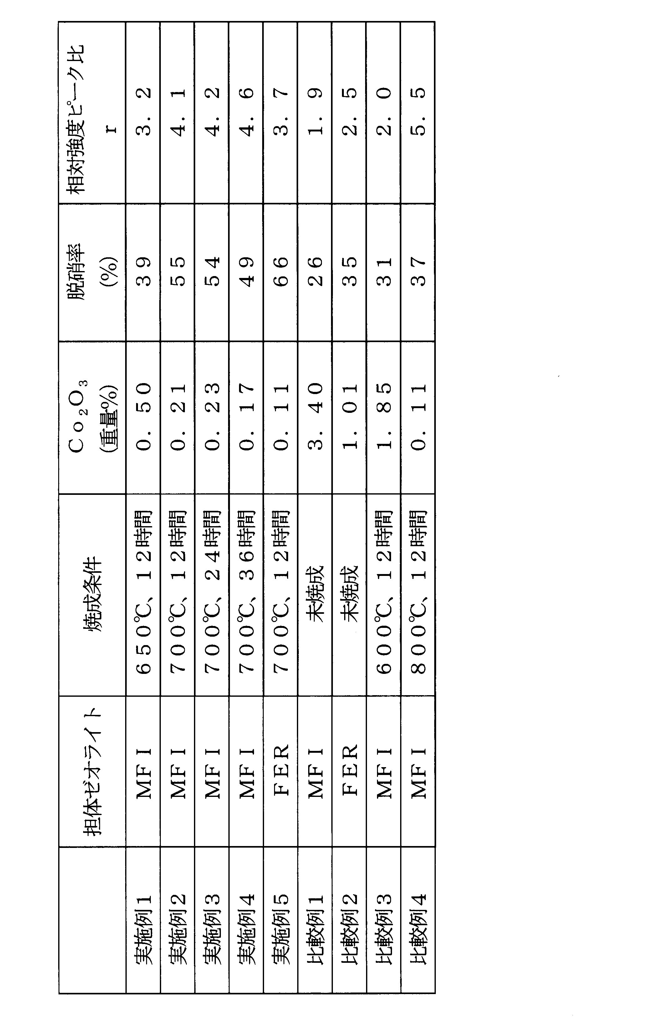

得られた脱硝触媒性能の評価試験の結果を、上記の表1にあわせて示した。
2:蒸発器
3:定量送液ポンプ
4:アルコール水溶液槽
Claims (6)
- 還元剤としてアルコールを添加した燃焼排ガスに接触させて、該排ガス中の窒素酸化物を除去する燃焼排ガスの浄化方法に用いられる脱硝触媒であって、前記脱硝触媒が、担体であるゼオライトに触媒金属が担持されたものであり、かつ前記脱硝触媒の粉末X線回折測定において回折角(2θ)=7.8~10.0°の回折ピーク高さIと、同回折角(2θ)=28.0~31.0°の回折ピーク高さJとの比r=I/Jが、3.0~5.0の範囲にあることを特徴とする、燃焼排ガス浄化用触媒。
- 担体であるゼオライトが、予め不活性ガス雰囲気下において焼成したゼオライトよりなるものであることを特徴とする、請求項1に記載の燃焼排ガス浄化用触媒。
- 触媒金属が、コバルト(Co)であることを特徴とする、請求項1に記載の燃焼排ガス浄化用触媒。
- 触媒金属が、コバルト(Co)であることを特徴とする、請求項2に記載の燃焼排ガス浄化用触媒。
- 還元剤としてのアルコールが、メタノール、またはエタノールであることを特徴とする、請求項1~4のうちのいずれか一項に記載の燃焼排ガス浄化用触媒。
- 燃焼排ガスの浄化方法であって、予め不活性ガス雰囲気下において焼成したゼオライトよりなる担体に触媒金属が担持されかつ粉末X線回折測定において回折角(2θ)=7.8~10.0°の回折ピーク高さIと、同回折角(2θ)=28.0~31.0°の回折ピーク高さJとの比r=I/Jが、3.0~5.0の範囲にある脱硝触媒に、還元剤としてアルコールを添加した燃焼排ガスを接触させることにより、排ガス中の窒素酸化物を除去することを特徴とする、燃焼排ガスの浄化方法。
Priority Applications (4)
| Application Number | Priority Date | Filing Date | Title |
|---|---|---|---|
| CN201580015047.8A CN106132539B (zh) | 2014-03-24 | 2015-03-23 | 燃烧废气净化用催化剂和燃烧废气的净化方法 |
| EP15769841.6A EP3124113A4 (en) | 2014-03-24 | 2015-03-23 | Combustion exhaust gas purifying catalyst and method for purifying combustion exhaust gas |
| KR1020167024714A KR102363752B1 (ko) | 2014-03-24 | 2015-03-23 | 연소배기가스 정화용 촉매 및 연소배기가스의 정화방법 |
| US15/125,730 US10112183B2 (en) | 2014-03-24 | 2015-03-23 | Catalyst for purifying combustion exhaust gas, and method for purifying combustion exhaust gas |
Applications Claiming Priority (2)
| Application Number | Priority Date | Filing Date | Title |
|---|---|---|---|
| JP2014060080A JP6326257B2 (ja) | 2014-03-24 | 2014-03-24 | 燃焼排ガス浄化用触媒、および燃焼排ガスの浄化方法 |
| JP2014-060080 | 2014-03-24 |
Publications (1)
| Publication Number | Publication Date |
|---|---|
| WO2015146913A1 true WO2015146913A1 (ja) | 2015-10-01 |
Family
ID=54195426
Family Applications (1)
| Application Number | Title | Priority Date | Filing Date |
|---|---|---|---|
| PCT/JP2015/058742 Ceased WO2015146913A1 (ja) | 2014-03-24 | 2015-03-23 | 燃焼排ガス浄化用触媒、および燃焼排ガスの浄化方法 |
Country Status (6)
| Country | Link |
|---|---|
| US (1) | US10112183B2 (ja) |
| EP (1) | EP3124113A4 (ja) |
| JP (1) | JP6326257B2 (ja) |
| KR (1) | KR102363752B1 (ja) |
| CN (1) | CN106132539B (ja) |
| WO (1) | WO2015146913A1 (ja) |
Families Citing this family (2)
| Publication number | Priority date | Publication date | Assignee | Title |
|---|---|---|---|---|
| JP6232223B2 (ja) * | 2013-07-25 | 2017-11-15 | 日立造船株式会社 | 排ガス浄化方法 |
| CN120054605A (zh) * | 2023-11-22 | 2025-05-30 | 陈海军 | 含钒fer型沸石及其应用 |
Citations (3)
| Publication number | Priority date | Publication date | Assignee | Title |
|---|---|---|---|---|
| JPH07303820A (ja) * | 1994-03-14 | 1995-11-21 | Sekiyu Sangyo Kasseika Center | 窒素酸化物の接触還元方法 |
| JPH1033947A (ja) * | 1996-07-24 | 1998-02-10 | Meidensha Corp | 排気ガス中の窒素酸化物の除去方法 |
| JP2013226545A (ja) * | 2012-03-30 | 2013-11-07 | Hitachi Zosen Corp | 燃焼排ガスの浄化方法、および脱硝触媒 |
Family Cites Families (7)
| Publication number | Priority date | Publication date | Assignee | Title |
|---|---|---|---|---|
| JPH0543221A (ja) * | 1991-08-16 | 1993-02-23 | Tosoh Corp | コバルト化合物含有ゼオライト及びその製造方法 |
| JPH0543222A (ja) * | 1991-08-16 | 1993-02-23 | Tosoh Corp | Co3O4含有ゼオライト及びその製造方法 |
| JP2004358454A (ja) | 2003-04-11 | 2004-12-24 | Sumitomo Metal Mining Co Ltd | 排ガス浄化触媒及び浄化方法 |
| JP2006220107A (ja) | 2005-02-14 | 2006-08-24 | Sumitomo Metal Mining Co Ltd | 排ガスの脱硝浄化方法及びその装置 |
| CN101723404A (zh) * | 2008-10-24 | 2010-06-09 | 北京化工大学 | 一种高过渡金属含量分子筛的制备方法 |
| EP2521615A1 (en) * | 2009-10-14 | 2012-11-14 | Basf Se | Copper containing levyne molecular sieve for selective reduction of nox |
| CN104812703B (zh) * | 2012-12-07 | 2018-05-29 | 埃克森美孚研究工程公司 | 具有改进形态的zsm-5晶体的合成 |
-
2014
- 2014-03-24 JP JP2014060080A patent/JP6326257B2/ja active Active
-
2015
- 2015-03-23 WO PCT/JP2015/058742 patent/WO2015146913A1/ja not_active Ceased
- 2015-03-23 US US15/125,730 patent/US10112183B2/en active Active
- 2015-03-23 KR KR1020167024714A patent/KR102363752B1/ko active Active
- 2015-03-23 CN CN201580015047.8A patent/CN106132539B/zh active Active
- 2015-03-23 EP EP15769841.6A patent/EP3124113A4/en not_active Withdrawn
Patent Citations (3)
| Publication number | Priority date | Publication date | Assignee | Title |
|---|---|---|---|---|
| JPH07303820A (ja) * | 1994-03-14 | 1995-11-21 | Sekiyu Sangyo Kasseika Center | 窒素酸化物の接触還元方法 |
| JPH1033947A (ja) * | 1996-07-24 | 1998-02-10 | Meidensha Corp | 排気ガス中の窒素酸化物の除去方法 |
| JP2013226545A (ja) * | 2012-03-30 | 2013-11-07 | Hitachi Zosen Corp | 燃焼排ガスの浄化方法、および脱硝触媒 |
Non-Patent Citations (2)
| Title |
|---|
| KEN OGURA ET AL.: "Pertormance ot Purification for Diesel Exhaust Gas over Cobalt Ion- exchanged ZSM-5 Catalyst", CATALYST, vol. 39, no. 2., March 1997 (1997-03-01), pages 205, XP008184961 * |
| See also references of EP3124113A4 * |
Also Published As
| Publication number | Publication date |
|---|---|
| CN106132539A (zh) | 2016-11-16 |
| CN106132539B (zh) | 2019-02-19 |
| US20170001181A1 (en) | 2017-01-05 |
| KR20160137995A (ko) | 2016-12-02 |
| US10112183B2 (en) | 2018-10-30 |
| JP6326257B2 (ja) | 2018-05-16 |
| EP3124113A4 (en) | 2017-09-27 |
| EP3124113A1 (en) | 2017-02-01 |
| JP2015182005A (ja) | 2015-10-22 |
| KR102363752B1 (ko) | 2022-02-15 |
Similar Documents
| Publication | Publication Date | Title |
|---|---|---|
| KR102180723B1 (ko) | 질소 산화물의 환원에 대한 희박/농후 노화에 대해 내구적인 소기공 분자 체 지지된 구리 촉매 | |
| JP6572133B2 (ja) | 燃焼排ガス浄化用触媒、および燃焼排ガスの浄化方法 | |
| KR101434936B1 (ko) | 선택적 촉매 환원용 바나듐 비함유 촉매 및 이의 제조방법 | |
| JP5987010B2 (ja) | ジルコニウム、セリウムおよびニオブを含む組成物を触媒として用いて、酸化窒素(NOx)を含有するガスを処理する方法 | |
| KR20160079935A (ko) | 선택적 암모니아 산화를 위한 이원기능 촉매 | |
| KR20140035323A (ko) | 금속 도핑된 제올라이트 및 제오타입의 제조 방법 및 질소 산화물의 촉매 정화에 대한 이들의 적용 | |
| JP2014528394A (ja) | 低リンチャバサイト | |
| CN104772162A (zh) | 低温NH3还原NOx的Zr-Ce-Mn-Fe/ZSM-5复合氧化物催化剂及其制备方法 | |
| JP6886776B2 (ja) | 排ガス浄化触媒 | |
| CN104772163A (zh) | 低温NH3还原NOx的Ce-Mn-Fe/ZSM-5复合氧化物催化剂及其制备方法 | |
| WO2013146729A1 (ja) | 燃焼排ガスの浄化方法、および脱硝触媒 | |
| JP6326257B2 (ja) | 燃焼排ガス浄化用触媒、および燃焼排ガスの浄化方法 | |
| CN104801335A (zh) | 低温NH3还原NOx的Zr-Ce-Mn/ZSM-5复合氧化物催化剂及其制备方法 | |
| JP6051084B2 (ja) | 燃焼排ガスの浄化方法、および脱硝触媒 | |
| JP6134552B2 (ja) | 燃焼排ガスの浄化方法、および脱硝触媒 | |
| CN112188929B (zh) | 用于nox选择性还原的包含afx结构沸石和bea结构沸石的混合物以及至少一种过渡金属的催化剂 | |
| JP6051083B2 (ja) | 燃焼排ガスの浄化方法、および脱硝触媒 | |
| WO2014087910A1 (ja) | 燃焼排ガス浄化用触媒およびこの触媒を用いる脱硝浄化方法 | |
| CN118973688A (zh) | 处理废气的方法及其系统 | |
| WO2015012202A1 (ja) | 排ガス浄化方法 | |
| WO2013069713A1 (ja) | 燃焼排ガス中の窒素酸化物の除去触媒および同触媒を用いる窒素酸化物の除去方法 | |
| CN104801336A (zh) | 低温NH3还原NOx的Zr-Mn-Fe/ZSM-5复合氧化物催化剂及其制备方法 |
Legal Events
| Date | Code | Title | Description |
|---|---|---|---|
| 121 | Ep: the epo has been informed by wipo that ep was designated in this application |
Ref document number: 15769841 Country of ref document: EP Kind code of ref document: A1 |
|
| ENP | Entry into the national phase |
Ref document number: 20167024714 Country of ref document: KR Kind code of ref document: A |
|
| WWE | Wipo information: entry into national phase |
Ref document number: 15125730 Country of ref document: US |
|
| NENP | Non-entry into the national phase |
Ref country code: DE |
|
| REEP | Request for entry into the european phase |
Ref document number: 2015769841 Country of ref document: EP |
|
| WWE | Wipo information: entry into national phase |
Ref document number: 2015769841 Country of ref document: EP |