WO2015147061A1 - Capteur de pression de combustion et son procédé de fabrication - Google Patents
Capteur de pression de combustion et son procédé de fabrication Download PDFInfo
- Publication number
- WO2015147061A1 WO2015147061A1 PCT/JP2015/059137 JP2015059137W WO2015147061A1 WO 2015147061 A1 WO2015147061 A1 WO 2015147061A1 JP 2015059137 W JP2015059137 W JP 2015059137W WO 2015147061 A1 WO2015147061 A1 WO 2015147061A1
- Authority
- WO
- WIPO (PCT)
- Prior art keywords
- pressure sensor
- combustion pressure
- combustion
- welding
- pressure
- Prior art date
- Legal status (The legal status is an assumption and is not a legal conclusion. Google has not performed a legal analysis and makes no representation as to the accuracy of the status listed.)
- Ceased
Links
Images










Classifications
-
- F—MECHANICAL ENGINEERING; LIGHTING; HEATING; WEAPONS; BLASTING
- F02—COMBUSTION ENGINES; HOT-GAS OR COMBUSTION-PRODUCT ENGINE PLANTS
- F02B—INTERNAL-COMBUSTION PISTON ENGINES; COMBUSTION ENGINES IN GENERAL
- F02B77/00—Component parts, details or accessories, not otherwise provided for
- F02B77/08—Safety, indicating, or supervising devices
- F02B77/085—Safety, indicating, or supervising devices with sensors measuring combustion processes, e.g. knocking, pressure, ionization, combustion flame
-
- B—PERFORMING OPERATIONS; TRANSPORTING
- B23—MACHINE TOOLS; METAL-WORKING NOT OTHERWISE PROVIDED FOR
- B23K—SOLDERING OR UNSOLDERING; WELDING; CLADDING OR PLATING BY SOLDERING OR WELDING; CUTTING BY APPLYING HEAT LOCALLY, e.g. FLAME CUTTING; WORKING BY LASER BEAM
- B23K26/00—Working by laser beam, e.g. welding, cutting or boring
- B23K26/20—Bonding
- B23K26/21—Bonding by welding
- B23K26/24—Seam welding
-
- G—PHYSICS
- G01—MEASURING; TESTING
- G01L—MEASURING FORCE, STRESS, TORQUE, WORK, MECHANICAL POWER, MECHANICAL EFFICIENCY, OR FLUID PRESSURE
- G01L19/00—Details of, or accessories for, apparatus for measuring steady or quasi-steady pressure of a fluent medium insofar as such details or accessories are not special to particular types of pressure gauges
- G01L19/06—Means for preventing overload or deleterious influence of the measured medium on the measuring device or vice versa
- G01L19/0627—Protection against aggressive medium in general
- G01L19/0645—Protection against aggressive medium in general using isolation membranes, specially adapted for protection
-
- G—PHYSICS
- G01—MEASURING; TESTING
- G01L—MEASURING FORCE, STRESS, TORQUE, WORK, MECHANICAL POWER, MECHANICAL EFFICIENCY, OR FLUID PRESSURE
- G01L19/00—Details of, or accessories for, apparatus for measuring steady or quasi-steady pressure of a fluent medium insofar as such details or accessories are not special to particular types of pressure gauges
- G01L19/14—Housings
- G01L19/142—Multiple part housings
-
- G—PHYSICS
- G01—MEASURING; TESTING
- G01L—MEASURING FORCE, STRESS, TORQUE, WORK, MECHANICAL POWER, MECHANICAL EFFICIENCY, OR FLUID PRESSURE
- G01L23/00—Devices or apparatus for measuring or indicating or recording rapid changes, such as oscillations, in the pressure of steam, gas, or liquid; Indicators for determining work or energy of steam, internal-combustion, or other fluid-pressure engines from the condition of the working fluid
- G01L23/08—Devices or apparatus for measuring or indicating or recording rapid changes, such as oscillations, in the pressure of steam, gas, or liquid; Indicators for determining work or energy of steam, internal-combustion, or other fluid-pressure engines from the condition of the working fluid operated electrically
- G01L23/10—Devices or apparatus for measuring or indicating or recording rapid changes, such as oscillations, in the pressure of steam, gas, or liquid; Indicators for determining work or energy of steam, internal-combustion, or other fluid-pressure engines from the condition of the working fluid operated electrically by pressure-sensitive members of the piezoelectric type
-
- G—PHYSICS
- G01—MEASURING; TESTING
- G01L—MEASURING FORCE, STRESS, TORQUE, WORK, MECHANICAL POWER, MECHANICAL EFFICIENCY, OR FLUID PRESSURE
- G01L9/00—Measuring steady of quasi-steady pressure of fluid or fluent solid material by electric or magnetic pressure-sensitive elements; Transmitting or indicating the displacement of mechanical pressure-sensitive elements, used to measure the steady or quasi-steady pressure of a fluid or fluent solid material, by electric or magnetic means
- G01L9/08—Measuring steady of quasi-steady pressure of fluid or fluent solid material by electric or magnetic pressure-sensitive elements; Transmitting or indicating the displacement of mechanical pressure-sensitive elements, used to measure the steady or quasi-steady pressure of a fluid or fluent solid material, by electric or magnetic means by making use of piezoelectric devices, i.e. electric circuits therefor
-
- G—PHYSICS
- G01—MEASURING; TESTING
- G01M—TESTING STATIC OR DYNAMIC BALANCE OF MACHINES OR STRUCTURES; TESTING OF STRUCTURES OR APPARATUS, NOT OTHERWISE PROVIDED FOR
- G01M15/00—Testing of engines
- G01M15/04—Testing internal-combustion engines
- G01M15/08—Testing internal-combustion engines by monitoring pressure in cylinders
Definitions
- the present invention relates to a combustion pressure sensor suitable for use in detecting a combustion pressure in a combustion chamber of an internal combustion engine and a method for manufacturing the same.
- Patent Document 1 a pressure sensor disclosed in Patent Document 1 is known as a combustion pressure sensor for detecting a combustion pressure in a combustion chamber of an internal combustion engine.
- This pressure sensor has a pressure receiving surface that receives the pressure to be measured.
- the pressure receiving surface is opposite to the pressure receiving image of the circular pressure receiving diaphragm that is distorted by receiving the pressure to be measured and the pressure receiving diaphragm.
- the pressure transmission member that is in contact with the other surface of the side and the other end side opposite to the one end of the pressure transmission member, and the force according to the pressure to be measured received by the pressure receiving diaphragm And a sensor chip on which a strain sensitive element that generates a signal corresponding to the sensor chip is formed, and a cylindrical member surrounding the pressure transmission member.
- the basic structure includes a cylindrical member.
- the front end of the case and the pressure receiving diaphragm are joined together by welding, and the pressure transmitting member and the pressure transmitting member located at the rear end of the center of the pressure receiving diaphragm are brought into contact with each other, thereby The rear end of the strain-sensitive elements and a structure for transmitting to the sensor chip is formed.
- a pressure detection device for detecting the combustion pressure in the combustion chamber of the internal combustion engine is exposed to high-temperature and high-pressure environments in the combustion chamber, while improving the detection accuracy and preloading the pressure receiving member. Therefore, it is used in an environment where a combustion pressure and a preload in the opposite direction are applied to the joint portion by welding on the pressure receiving member side and the case member side.
- the joint depth at this joint portion is required to have a uniform depth with no unevenness over the entire circumference, but with the conventional combustion pressure sensor, it is not easy to ensure uniformity, and as a result, the diaphragm There is a problem in that it is difficult to obtain a combustion pressure sensor with high detection accuracy due to variations in the effective pressure receiving radius and the effective sensitivity.
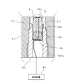
- FIG. 23 is a schematic diagram showing the pressure sensor described in Patent Document 1.
- FIG. 24 (a) is a partially extracted enlarged view of a circle L portion in FIG. 23, and FIGS. 24 (b) to (d). ) Shows a partially extracted enlarged view of the circle X portion in FIG.
- a pressure sensor 5j shown in FIG. 23 includes a diaphragm 40j welded to a front end portion of a hollow cylindrical housing 31j.
- the displacement of the diaphragm 40j is transmitted to the sensor chip on which the strain sensitive element 10j on the rear end side is formed via the pressure transmitting member 50j contacting the pressure transmitting portion located at the rear end of the central portion and the metal stem 65j. Is done.
- the housing 31j is fixed to the housing 32j, and the housing 32j is attached to the cylinder head 4j by a screw portion 32nj.
- the combustion pressure generated in the combustion chamber C is received by the diaphragm 40j and transmitted to the strain sensitive element 10j via the pressure transmission member 50j.
- a change in resistance value due to strain is converted as a signal and applied to the control device 6j.
- 10a indicates a pressure transmitting portion of the diaphragm 40j
- 10b indicates a thin strained portion
- 10c indicates an inner concave portion
- 10d indicates an outer peripheral wall (welded portion).
- y indicates a position where the entire diaphragm 40j is deformed due to thermal strain by a one-dot chain line
- m indicates an effective pressure receiving radius of the pressure receiving portion.
- the diaphragm 40j and the housing 31j are welded over the entire circumference to provide a joint along the entire circumference.
- Conditions vary depending on the end, and it is not easy to make the welding depth constant.
- FIGS. 24B to 24D variations as shown in FIGS. 24B to 24D occur.
- FIG. 24B shows a case where the welding depth is insufficient, and the welding depth is indicated by t1.
- the effective pressure receiving radius of the diaphragm at this time is i.
- FIG. 24C shows an ideal welding depth, and the welding depth is indicated by t2.
- the effective pressure receiving radius of the diaphragm at this time is m.
- FIG. 24D shows a case where the welding depth is excessive, and the welding depth is indicated by t3.
- the effective pressure receiving radius of the diaphragm at this time is n.
- the welding depth and further the effective pressure receiving radius (i, m, n) of the diaphragm vary during welding around the circuit, and as a result, the sensitivity of the combustion pressure varies. .
- Patent Document 1 intends to obtain the optimum value of the dimensions of the respective parts 10a, 10b, 10c, and 10d in the pressure receiving part by using SIM analysis, and to reduce the variation in sensitivity due to thermal distortion. Since the basic cause is in the welding process, there is a limit to relying on the technique of Patent Document 1 from the viewpoint of eliminating variations in effective sensitivity and realizing a combustion pressure sensor with high detection accuracy.
- An object of the present invention is to provide a combustion pressure sensor and a method for manufacturing the same that solve the problems existing in the background art.
- the combustion pressure sensor (5, 5A,%) includes at least a case member (31 %) provided with an opening having a joint surface (31a %) on the distal end side, and a case.
- a pressure receiving member (40 %) having a joining surface (41a %) that closes the opening by surface contact with the joining surface (31a %) of the member (31 %), and a combustion pressure; (31a and 41a%)
- a welded portion (J2%) That joins each other and a piezoelectric member that is accommodated in a case member (31%) And converts the applied pressure based on the combustion pressure transmitted from the pressure receiving member (40.
- the one joining surface (41a %) is provided on one edge side of at least one joining surface (41a ). Limited to constant welding depth t ... from the other edge And a predetermined relief portion (90%) That forms a predetermined gap with respect to the other joint surface (31a%) Facing each other, and at least limited from the other edge of the one joint surface (41a).
- a welded portion (J2%) Including all the joint surfaces (41a%) Is provided.
- the relief portion (90%) Can be provided by a step portion (41b%) Formed on at least one of the pressure receiving member (40%) Or the case member (31). Further, at least one of the pressure receiving members (40%) Or the case members (31%) Can be provided with a protruding portion (31b%) That covers the escape portion (90%) By protruding from one edge.
- the joining surface 31a joined to the joining surface 41a along the outer periphery of the said diaphragm 40 is used as a case member (31 ).
- a cylindrical housing 31 having the following can be used.
- the combustion pressure sensor (5, 5A%) Can be integrated with a functional component attached to the internal combustion engine 501, and an injector, a spark plug, or a glow plug can be applied to this functional component.
- the pressure receiving member (40%) Uses a pressure receiving ring block 514A on which combustion pressure acts, and the case member (31%) Has a bonding surface 514a along the outer periphery of the pressure receiving ring block 514A.
- a cylindrical outer housing 512A having a joining surface 512a joined to a joining surface 514a along the inner periphery of the pressure receiving ring block 514A and a cylindrical outer housing 511A having a joining surface 511a to be joined can be used.
- the combustion pressure acts on the joint surface (31a%) Provided in the opening provided on the tip side of the case member (31).
- the contact surfaces (41a %) provided on the pressure receiving members (40 %) are brought into surface contact, and the joint surfaces (31a and 41a %) are joined to each other via welds (J2 %) to close the opening.
- the case member (31%) Accommodates the piezoelectric elements (10%) That convert the pressure applied based on the combustion pressure transmitted from the pressure receiving members (40.
- at least one joining surface (41a ...) is limited to a certain welding depth t ...
- a predetermined relief portion (90) That forms a predetermined gap is provided, and at the time of welding, welding is performed from the other edge of one joint surface (41a. It is characterized by providing a welded portion (J2%) Including all of the above.
- At least one of the pressure receiving member (40 %) or the case member (31 %) is formed with a protrusion (31b %) protruding from one edge, and the protrusion
- the escape portion (90 %) can be covered by the portion (31b ).
- welding beams 400... Can be used for welding.
- the combustion pressure sensor (5, 5A%) has a constant one joint surface (41a%) From the other edge on one edge side of at least one joint surface (41a).
- a predetermined relief portion (90%) Is provided that forms a predetermined gap with respect to the other joining surface (31a%) That is limited to the welding depth t and is opposed to the other joining surface (31a). Since the welded part (J2%) Including at least all of the limited joint surfaces (41a%) Is provided from the other edge, the welding depth t can be made constant at all welding positions.
- a combustion pressure sensor (5, 5A %) can be provided.
- the method for manufacturing a combustion pressure sensor according to the present invention is such that at least one joint surface (41a %) is welded to one edge side of at least one joint surface (41a %) from the other edge in advance.
- a predetermined relief portion (90%) That is limited to the depth t... And forms a predetermined gap with respect to the other joint surface (31a%) Facing the other is provided.
- To provide the welded portion (J2%) Including at least the limited joint surface (41a%) By welding from the other edge, so that the combustion pressure sensor (5, 5A. Can be manufactured.
- a relief part (90 %) is provided by the level
- securing the length t it can be easily carried out with a small number of manufacturing steps such as cutting.
- At least one of the pressure receiving member (40%) Or the case member (31%) is provided with a protruding portion (31b%) That covers the relief portion (90%) By protruding from one edge. If provided, the spatter of welding spatter can be kept only in the escape portion (90). Therefore, defects caused by welding spatter such as defective insulation of the live parts due to the spatter scattered in the pressure detection portion. Can be eliminated.
- the combustion pressure sensor (5, 5A) uses the diaphragm 40 on which the combustion pressure acts on the pressure receiving member (40%) And the case member (31%)
- a cylindrical housing 31 having a joint surface 31a joined to a joint surface 41a along the outer periphery of the diaphragm 40 can be used, or a pressure receiving ring block in which combustion pressure acts on the pressure receiving member (40 ).
- a cylindrical outer casing 511A having a joint surface 511a joined to the joint surface 514a along the outer periphery of the pressure receiving ring block 514A and an inner side of the pressure receiving ring block 514A are used.
- the combustion pressure sensor (5, 5A) can be configured as a combustion pressure sensor in a form that can be independently attached to the combustion chamber of the internal combustion engine and is attached to a functional component attached to the combustion chamber of the internal combustion engine. It is possible to provide a combustion pressure sensor (5, 5A%) Having high versatility and applicability, and a manufacturing method thereof.
- the combustion pressure sensor (5, 5A%) Is integrated with a functional part attached to the internal combustion engine 501, and in particular, an injector, a spark plug or a glow plug is applied as the functional part. Then, it can be provided as an optimum combustion pressure sensor (5, 5A%) That can be used for the internal combustion engine 501 mounted on an automobile or the like and a method for manufacturing the same.
- the welded portion (J2%) According to the present invention can be implemented as an optimum form, and the strength exceeding the welding depth t. It is possible to flexibly cope with conditions set in (welding capacity), and the welding process can be easily optimized.
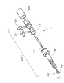
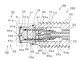
- FIG. 1 is a schematic configuration diagram of an internal combustion engine to which a first embodiment of the present invention is applied; An enlarged view of area A in FIG. An exploded perspective view of the combustion pressure sensor according to the first embodiment, Sectional drawing of the combustion pressure sensor which concerns on 1st Embodiment, Sectional drawing which shows a part of combustion pressure sensor of Example 1 which concerns on 1st Embodiment, FIG. 5 is an enlarged view of extraction of the D region in FIG. Sectional drawing which shows a part of combustion pressure sensor of Example 2 which concerns on 1st Embodiment, FIG. 7 is an enlarged view of extraction of the F region in FIG. The fragmentary sectional view which shows the combustion pressure sensor of Example 3 which concerns on 1st Embodiment, FIG.
- FIG. 9 is an enlarged view of extraction of the G region in FIG.
- FIG. 11 is an enlarged view of extraction of the H region in FIG.
- FIG. 13 is an enlarged view of extraction of region B in FIG.
- FIG. 15 is an explanatory perspective view when the pressure detection unit shown in FIG. 14 is mounted on a functional component (injector);
- FIG. 17 is an enlarged view of the I region in FIG.
- FIG. 19 is an enlarged view of extraction of the M region in FIG.
- FIG. 21 is an enlarged view of extraction of the K region in FIG.
- FIG. 23 is an enlarged view of the L region shown in FIG.
- the combustion pressure sensor according to the present embodiment relates to an improvement in joining between a pressure receiving member that receives the combustion pressure and a case member that holds the pressure receiving member and the pressure detection unit.
- the welding depth can be made constant, and the spatter of the welding spatter can be prevented to eliminate problems such as poor insulation of the pressure detection unit to the live part.
- the illustrated first embodiment is directed to a welded part in a so-called cylinder-type combustion pressure sensor, which is attached to a combustion chamber of an internal combustion engine alone.
- the illustrated second embodiment is an injector, It is intended for a welded portion in a so-called ring-type combustion pressure sensor, which is attached to a functional part such as a spark plug and attached to a combustion chamber.
- FIG. 1 shows a state in which a combustion pressure sensor 5 according to the first embodiment is incorporated in a general internal combustion engine 1 as an example
- FIG. 2 shows an enlarged view of a region A in FIG.
- the internal combustion engine 1 includes a cylinder block 2 including a cylinder 2a, a piston 3 that reciprocates in the cylinder 2a, and a cylinder head 4.
- a combustion chamber C is formed.
- the internal combustion engine 1 is usually attached to the cylinder head 4 and an ignition plug (not shown) for exploding the air-fuel mixture in the combustion chamber C, and attached to the cylinder head 4 and the combustion chamber. And an injector (not shown) for injecting fuel into C.
- the cylinder head 4 has a communication hole 4a that connects the combustion chamber C in which the combustion pressure sensor 5 according to the present embodiment is mounted and the outside, and the combustion pressure sensor 5 is attached to the communication hole 4a.
- the combustion pressure sensor 5 is interposed between the cylinder head 4 and is fixed together with a seal member 7 for keeping the air tightness in the combustion chamber C together with a screw formed in the communication hole 4a.
- the internal combustion engine 1 includes a transmission cable 8 for transmitting a pressure signal detected by the combustion pressure sensor 5 and a control device 6 that processes the sent pressure signal and sends a predetermined control signal to the internal combustion engine 1. I have.
- reference numeral 4 a denotes the communication hole that communicates the combustion chamber C formed in the cylinder head 4 with the outside. From the combustion chamber C side, the shape of the communication hole 4a is the first hole 4b, the inclined part 4c whose diameter gradually increases from the hole diameter of the first hole 4b, and the first hole 4b. And a second hole 4d larger than the hole diameter.
- a female screw part 4e is formed in the peripheral hole wall forming the second hole part 4d, and the male screw formed in the casing of the combustion pressure sensor 5 is screwed in, so that the first seal member 71 is interposed. Tighten and fix.
- the combustion pressure sensor 5 includes a diaphragm 40 at a position facing the combustion chamber C, with the pressure detection unit 100 at the tip of the combustion pressure sensor 5 serving as a pressure receiving unit.
- the second seal member 72 is interposed between the abutting portion of the pressure detection unit 100 of the combustion pressure sensor 5 and the inclined portion 4 c of the communication hole 4 a formed in the cylinder head 4.
- a connector portion 233 provided with a signal processing unit 200 is provided on the outer side of the cylinder head 4.
- the connector unit 233 is connected to the control device 6 via the connector 8a and the transmission cable 8 that transmits the pressure signal.
- the hook provided in the connector 8a is engaged with and locked in the hole 233a formed in the connector portion 223.
- the diaphragm 40 side located on the left side is the front end side of the combustion pressure sensor 5
- the signal processing unit 200 side located on the right side is the rear end side of the combustion pressure sensor 5.
- the combustion pressure sensor 5 includes a pressure detection unit 100 having a piezoelectric element that changes the combustion pressure generated in the combustion chamber C into an electrical signal, and a signal processing unit 200 that transmits and processes a signal from the pressure detection unit 100.
- a member that holds the pressure detection unit 100 having the diaphragm 40 is a casing 32.
- the casing 32 has a screw part and a hexagonal nut part for fixing to the cylinder head 4 on the outside, and on the other hand, the casing 32 has a through-hole inside and has an insulating member 23 for housing the circuit board part 21. Accommodates the tip.
- the through-hole formed inside the insulating member 23 accommodates the conductive member 22 that performs electrical connection with the pressure detection unit 100.
- the pressure detection unit 100 is inserted into the hole on the distal end side of the housing 32 and fixed to the housing 32 by welding.
- the holding member 300 inserted together with the circuit board part 21 into the hole on the rear end side, and inserting the holding member 300 inserted together with the circuit board part 21 into the groove on the rear end side. Fix it.
- the circuit board portion 21 can be kept sealed by inserting the O-ring 24 into the groove portion of the insulating member 23.
- the front end side of the conductive member 22 is electrically connected to the pressure detection unit 100 by a coil spring described later, and the connection portion 22 b of the conductive member 22 is connected to the circuit board portion 21 on the rear end side. It is electrically connected and fixed by soldering to the pattern portion. Further, the first connection pin 21 b is connected to the circuit board unit 21, and the circuit board unit 21 is grounded to the housing 32. Further, the three second connection pins 21c are soldered to the pattern portion of the circuit board portion 21, and the connection pins 21c are inserted into the connector 8 (see FIG. 2). Thereby, the board
- FIG. 5 shows an enlarged view of the pressure detection unit 100 of FIG.
- the pressure detection unit 100 includes a housing 31 that is a frame of the pressure detection unit 100, a diaphragm 40 that is provided so as to close the opening on the front end side of the housing 31 and receives the pressure (combustion pressure) of the combustion chamber C, A pressure transmission member 50 that transmits the displacement of the diaphragm 40 due to pressure by contacting the rear end surface 42c of the protrusion 42a formed on the diaphragm 40, and pressure (pressurizing force) from the pressure transmission member 50 by contacting the pressure transmission member 50.
- the second electrode part 55 that supports the piezoelectric element 10 and receives the generated electric charge as an electric signal, and supports and insulates the second electrode part 55.
- an end surface 31a is formed on the front end side of the housing 31, and a ring-shaped protrusion 31b along the circumferential direction is provided on the inner peripheral surface side of the end surface 31a as shown in FIG. It protrudes from the end surface 31a.
- the diaphragm 40 has a cylindrical cylindrical portion 41 and an inner portion 42 formed inside thereof.
- An end surface (joint surface) 41 a formed on the rear end side of the cylindrical portion 41 abuts on an end surface (joint surface) 31 a formed on the front end side of the housing 31.
- a ring-shaped stepped portion 41b is formed on the center side of the end surface 41a.
- the inner portion 42 is a thin disc-like member provided so as to close the opening on the front end side of the cylindrical portion 41, and a protruding portion 42a that protrudes from the rear end surface toward the piezoelectric element 10 is provided in the central portion.
- the inner portion 42 has a concave portion 42b at the center portion on the front end side.
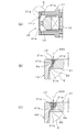
- FIGS. 6A is an enlarged view of the D region in FIG. 5, and FIGS. 6B and 6C are enlarged views of the E region in FIG. 6A.
- the pressure detector 100 can obtain a predetermined performance by welding and fixing the welds in a predetermined order and by a predetermined method.
- This ⁇ mark does not represent the shape of the weld, it simply indicates the position of the weld.
- welding uses a laser welding system to weld continuously over one circumference (entire circumference) and seal the weld surface. This welding method can be similarly applied to other embodiments described later.
- the weld J1 is welded.
- the cylindrical portion of the pressure member 80 is passed from the rear end side of the support member 65.
- the ring-shaped protrusion 65a formed on the outer periphery of the support member 65 is pushed in until the ring-shaped protrusion 80a formed on the inner periphery of the pressure member 80 is hooked.
- the outer diameter of the projection 65a formed on the support member 65 is formed larger than the inner diameter of the corresponding pressure member 80, and is fitted (press-fit) by so-called interference fit.
- the insulating ring 60, the second electrode portion 55, the piezoelectric element 10, and the pressure transmission member 50 are inserted in this order from the distal end side of the pressure member 80.
- a preload is applied to increase the sensitivity and linearity of the piezoelectric element 10.
- a predetermined load is applied to the protrusion 80 a of the pressure member 80 and the pressure transmission member 50 in the direction in which the piezoelectric element 10 is sandwiched, and the distal end side of the pressure member 80 is engaged with the pressure transmission member 50 ( Weld and fix to the peripheral surface.
- the welding part J1 can be provided and a piezoelectric element part can be obtained.
- the welds J2 and J3 are welded.
- the piezoelectric element portion described above is assembled to the housing 31.
- the piezoelectric element portion is inserted from the front end side of the housing 31 and temporarily inserted to the innermost end.
- the joint surface 31 a of the housing 31 and the joint surface 41 a of the diaphragm 40 are brought into contact with each other.
- the diaphragm 40 is used as a guide to fit to a protrusion 31b formed on the joint surface 31a of the housing 31 by so-called clearance fitting.
- the welded beam J2 is welded to the joint surface by the welding beam 400.
- FIG. 6B shows a state in which the joint surface 41a of the diaphragm 40 and the joint surface 31a of the housing 31 are in contact with each other and the welded portion J2 is provided.
- Reference numeral 400 denotes a welding beam from the outer peripheral side.
- the welding beam 400 is set to reach a depth slightly exceeding the welding distance t.
- the step portion 41b is formed on the joint surface 41a of the diaphragm 40, when the diaphragm 40 and the housing 31 are brought into contact with each other, a gap between the escape portion 90 is formed by the joint surface 31a and the step portion 41b. The Thereby, the welding part J2 of the diaphragm 40 and the housing 31 does not advance beyond the welding distance t.
- FIG. 6C shows a state where the welding beam 400 has reached further deeper. Even in this case, the presence of the escape portion 90 indicates that the welded portion J2 does not advance beyond the welding distance t.
- the welding distance t it is possible to keep the welding distance t equal to the welding depth constant by selecting the welding distance t to be at least equal to the influence of thermal inertia and the like. Become. Moreover, since the protrusion 31b provided on the joint surface 31a of the housing 31 is formed so as to face the welded portion J2 with the stepped portion 41b provided on the diaphragm 40 interposed therebetween, the spatter of the welding spatter 95 generated during welding is prevented. Since the function of blocking and retaining in the escape portion 90 is exhibited, there is also a secondary effect that can avoid the problem of scattering in a space where the piezoelectric element is present.
- a predetermined load is applied to the piezoelectric element portion temporarily inserted in the housing 31 from the rear end surface side to the front end surface side of the support member 65.
- the projecting portion 42c of the diaphragm 40 and the abutting surface 50a of the pressure transmitting member 50 come into contact with each other, and when the housing 31 and the support member 65 are displaced by a predetermined amount.
- Welding is performed by the welding beam 400 described above. Thereby, the welding part J3 can be provided and the pressure detection part 100 can be obtained.
- the weld J4 is welded.
- the pressure detection unit 100 is fitted to the inner peripheral portion on the distal end side of the housing 32.
- the coil spring 70 is engaged with the protruding portion 55 a of the second electrode portion 55.
- the conductive member 22 is assembled in a compressed state in the hole 22a.
- the conductive member 22 is fitted in the hole on the rear end side of the support member 65 in the state where the leading end portion 23a of the insulating member 23 is fitted in the hole of the insulating member 23.
- the welding of the ring-shaped protrusion of the pressure detection unit 100 and the end surface on the front end side of the housing 32 is performed by the welding beam 400 described above.
- the welding part J4 can be provided, the pressure detection part 100 and the signal processing part 200 are electrically connected, and the combustion pressure sensor 5A is completed.
- the combustion pressure sensor 5A has, as a basic structure, at least surface contact with the housing 31 provided with the opening having the joint surface 31a on the distal end side and the joint surface 31a of the housing 31.
- a diaphragm 40 having a joint surface 41a that closes the opening and on which combustion pressure acts, a welded portion J2 that joins the joint surfaces 31a and 41a together, and a combustion that is housed in the housing 31 and transmitted from the diaphragm 40
- a piezoelectric element 10 that converts a pressure based on pressure into a signal, and according to the present invention, at least one joint surface 41a is provided with a constant welding depth from the other edge to the one joint surface 41a.
- a predetermined relief portion 90 that forms a predetermined gap with respect to the other joint surface 31a facing the other, and From the other edge of the mating surface 41a, it is provided with a weld J2 including all bonding surface 41a that is at least limited.
- the end face 10a on the front end side of the piezoelectric element 10 is electrically connected to the metal housing 31 via the metal pressure transmission member 50 and the metal diaphragm 40.
- one of the first connection pins 21 b is soldered to the circuit board unit 21, and the other is in a pin hole provided in the metal housing 32. Press fit.
- the GND of the circuit board portion 21 is grounded to the housing 32.
- casing 32 and the housing 31 were joined via the welding part J4 mentioned above, they are electrically connected.
- the end face on the rear end side of the piezoelectric element 10 is soldered to the circuit board portion 21 from the metal second electrode portion 55 and the protruding portion 55a through the coil spring 70 and the metal conductive member 22, Connected.
- the second electrode portion 55 and the protruding portion 55a are electrically insulated from the surrounding support member 65 by the insulating ring 60 made of an insulator, and are also away from the inner peripheral surface of the pressure member 80. Electrically insulated.
- the step portion 41b is provided on the joint surface 41a of the diaphragm 40 in the combustion pressure sensor that is mounted in the combustion chamber C alone.
- the escape portion 90 where the diaphragm 40 and the housing 31 do not come into contact with each other can be provided.
- the welding depth (welding distance t) can be made constant along the circumferential direction by the relief portion 90, the effective pressure receiving diameter of the diaphragm 40 can be made constant, and high accuracy with suppressed sensitivity deviation. It is possible to provide the combustion pressure sensor 5A that can secure the pressure signal of.
- the protrusion 31b exists at a position facing the welded portion J2 with the escape portion 90 of the housing 31 interposed therebetween, the spatter of the welding spatter 95 is prevented, and problems such as poor insulation to the live parts in the pressure detection unit As a highly reliable combustion pressure sensor 5A, it is possible to prevent welding spatter 95 from scattering against the contact portion between the diaphragm 40 and the pressure transmission member 50 and to suppress wear deterioration of the contact portion. Can be provided.
- the strength of the welding beam 400 such as a laser is preferably set so that the welding depth exceeds the welding distance t between the housing 31 and the diaphragm 40 at least in consideration of the influence of thermal inertia and the like.
- the projection 31b is provided on the housing 31 and the step 40b is provided on the diaphragm 40.
- the projection 31b is provided on the diaphragm 40 and the step 41b is provided on the housing 31. May be provided.
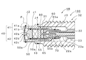
- FIG. 7 is a cross-sectional view of the pressure detection unit 100 of the combustion pressure sensor 5B
- FIG. 8 is an enlarged view of a region F in FIG.
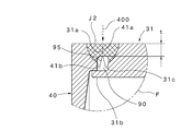
- the combustion pressure sensor 5B shown in FIG. 7 includes a stepped portion similar to the stepped portion 41b on the joint surface 31a of the housing 31 in addition to the configuration of the joint surface on the diaphragm 40 side shown in the combustion pressure sensor 5A according to the first embodiment. The difference is that 31c is provided. Since other basic configurations and assembly procedures are the same as those in the first embodiment, the same parts (same components) are denoted by the same reference numerals, and a part of overlapping description is omitted. The same number is assigned to the same part and the same component, and the alphabet “B” attached to the number indicates the second embodiment. Incidentally, in Example 1, “A” is attached.
- the step portion 31 c is also formed in the joint portion 31 a on the housing 31 side. Therefore, when the step portion 41 b formed in the diaphragm 40 is combined, the diaphragm 40 and the housing 31 are connected. In addition, a clearance 90 as shown in FIG. 8 can be formed. Therefore, in the combustion pressure sensor 5B according to the second embodiment, the flank portion 90 according to the first embodiment can be enlarged approximately twice as much as the flank portion 90 according to the first embodiment. Can be.
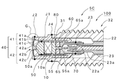
- FIG. 9 is a cross-sectional view of the pressure detection unit 100 of the combustion pressure sensor 5C
- FIG. 10 is an enlarged view of a region G in FIG.
- the combustion pressure sensor 5C is different from the combustion pressure sensor 5A according to the first embodiment described above in that a protrusion 41c similar to the protrusion 31b described above is provided on the diaphragm 40 side. Since the other basic configuration is the same as that of the first embodiment, the same parts (same components) are denoted by the same reference numerals, and a part of the overlapping description is omitted. The same number is assigned to the same part and the same component, and the alphabet “C” attached to the number indicates the third embodiment.
- the cylindrical portion 41 of the diaphragm 40 includes a protruding portion 41 c in addition to the contact surface 41 a and the stepped portion 41 b to the housing 31.
- a notch 31d is provided on the inner diameter side of the housing 31 corresponding to the protrusion 41c, and the protrusion 41c of the diaphragm 40 is configured to overlap. Therefore, the combustion pressure sensor 5C according to the third embodiment can obtain the same effects as the combustion pressure sensor 5A according to the first embodiment described above.
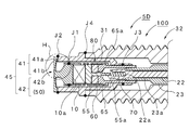
- FIG. 11 is a cross-sectional view of the pressure detection unit 100 of the combustion pressure sensor 5D
- FIG. 12 is an enlarged view of a region H in FIG.
- a combustion pressure sensor 5D shown in FIG. 11 integrates a diaphragm 40 and a pressure transmission member 50 with respect to the combustion pressure sensor 5A according to the first embodiment described above, and includes a diaphragm 45 in which the functions of these two members become one. The point used is different.
- the configuration of the joining surface 41a and the stepped portion 41b of the cylindrical portion 41 of the diaphragm 45, and the configuration of the joining surface 31a and the protruding portion 31b of the housing 31 are the same as those in the first embodiment. Further, the same applies to the welding method, and since the escape portion 90 and the protruding portion 31b are provided, the same effect as that of the combustion pressure sensor 5A according to the first embodiment can be obtained. Since the basic configuration and assembly procedure in the combustion pressure sensor 5D are the same as those in the first embodiment, the same parts (same components) are denoted by the same reference numerals, and a part of the overlapping description is omitted. The same number is assigned to the same part and the same component, and the alphabet “D” attached to the number indicates the fourth embodiment.
- FIG. 13 shows a state in which the combustion pressure sensor 5 according to the second embodiment is incorporated in a general internal combustion engine 1 as an example
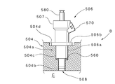
- FIGS. 14 to 16 show the combustion pressure sensor 508 according to the second embodiment. The structure is shown.
- FIG. 13 is a schematic configuration diagram of the internal combustion engine 501
- FIG. 14 is an enlarged view of a part B in FIG.
- the combustion pressure sensor 508 according to the second embodiment is a combustion pressure sensor that is integrally combined with a functional component such as an injector or a spark plug attached to the combustion chamber C.
- FIG. 13 shows an internal combustion engine 501 equipped with an injector unit 506 provided with a combustion pressure sensor 508 according to the second embodiment.
- the internal combustion engine 501 includes a cylinder block 502 having a cylinder 502a, a piston 503, and a cylinder head 504, and includes a combustion chamber C therein.
- the internal combustion engine 501 is attached to the cylinder head 504, thereby injecting fuel into the combustion chamber C, and attached to the cylinder head 504 to burn the air-fuel mixture in the combustion chamber C.
- a spark plug 505 is abbreviated by a dashed line.
- the injector unit 506 includes a combustion pressure sensor 508 that is integrally provided at the tip of the injector 507.
- the cylinder head 504 has a communication hole 504a communicating with the combustion chamber C for attaching the injector unit 506 and the outside.
- the communication hole 504a has a first hole 504b, a second hole 504c larger than the hole diameter of the first hole 504b, and a hole diameter larger than the hole diameter of the second hole 504c from the combustion chamber C side. 3 holes 504d.
- the injector unit 506 is attached so as to penetrate through the communication hole 504a, and is configured such that the combustion pressure sensor 508 is positioned near the combustion chamber C of the first hole 504b.
- the outer diameter of the combustion pressure sensor 508 is The hole diameter of the first hole 504b is slightly smaller.
- the body 506a of the injector unit 506 is inserted through the gasket 560 into the second hole 504c, and is fitted by a so-called clearance fit.
- the flange portion 506b of the injector unit 506 is disposed in the third hole portion 504d.
- the upper surface of the flange portion 506b of the injector unit 506 is clamped by a clamping device (not shown) provided outside the cylinder head 504, and the gasket 560 is compressed. Thereby, airtightness is maintained so that air-fuel mixture and combustion gas do not leak from the combustion chamber C side. Further, as shown in FIG.
- the injector unit 506 is connected to an electrical connector portion 570 for connection for transmitting a pressure signal detected by a combustion pressure sensor 508 attached to the outer periphery of the tip portion to the outside, and an injector 507.
- a fuel connector portion 580 for supplying fuel is provided.
- the internal combustion engine 501 has a signal processing unit 700 that receives and amplifies an electric signal that is a weak charge obtained from a piezoelectric element, and a control device that receives the processed signal and sends a predetermined control signal to the internal combustion engine. 600.
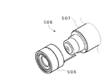
- FIGS. 15 and 16 shows a configuration in which the combustion pressure sensor 508 is mounted on the injector 507
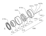
- FIG. 16 shows an exploded perspective view of the combustion pressure sensor 508.
- FIG. 15 shows a state in which the ring-type combustion pressure sensor 508 is attached to the tip of the injector 507. After the attachment, the joint portion between the two is welded to form an integrated injector unit 506. Composed.
- the combustion pressure sensor 508 according to the second embodiment includes a pressure detection unit 510 having a piezoelectric element that changes the combustion pressure generated in the combustion chamber C into an electrical signal, and a signal from the pressure detection unit 510.
- a transmission unit 550 for transmission is provided.
- the pressure receiving ring block 514 side located on the left side in FIG. 16 is the front end side of the combustion pressure sensor 508, and the transmission unit 550 side on the right side in the figure is the rear end side of the combustion pressure sensor 508. It becomes.
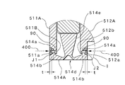
- FIG. 17 is a cross-sectional view of an injector unit 506A in which a combustion pressure sensor 508A is incorporated in the injector 507
- FIG. 18 is an enlarged view of an I region in FIG.
- the combustion pressure sensor 508A includes a pressure detection unit 510A having a function of detecting pressure, and a transmission unit 550 that transmits the pressure detected by the pressure detection unit 510A to the outside as an electrical signal.
- the pressure detection unit 510A has a cylindrical shape as a whole, and the inner opening 510a accommodates the tip of the injector 507. Thereby, the front-end
- the transmission unit 550 accommodates the end of the connection terminal 552 on the front end face side in the pressure detection unit 510A, and the transmission wire 551 on the rear end face side through the signal wire guide hole provided in the injector 507.
- the rear end portion of the connection terminal 552 and the conductor portion on the front end surface side of the transmission wire 551 are electrically connected by caulking the connection pipe 553.
- the transmission unit 550 further includes a coil spring 556 that presses and electrically connects the connection terminal 552, a positioning tube 555 that guides and insulates the connection terminal 552, and an O-ring 557 that seals the periphery of the connection pipe 553. Is provided.
- the pressure detection unit 510A includes a front outer casing 511A having a cylindrical shape, a front inner casing 512A having a cylindrical shape, a rear casing 513 having a cylindrical shape, and a pressure receiving ring block having an annular shape. 514A.
- the front outer casing 511A, the front inner casing 512A, the rear casing 513, and the pressure-receiving ring block 514A are assembled and then coupled through the respective welded portions, whereby the casing as a whole in the pressure detector 510A. It has a function. Further, as shown in FIG.
- the pressure receiving ring block 514A is exposed to the combustion chamber C side to receive the combustion pressure from the combustion chamber 514d, and the pressure received by the pressure receiving portion 514d on the back side of the pressure receiving portion.
- a transmission portion 514e for transmitting (displacement) to the pressure transmission ring 515 is integrated with the pressure transmission ring 515.
- an internal space 510b surrounded by the front outer casing 511A, the front inner casing 512A, the rear casing 513, and the pressure receiving ring block 514A is formed.
- a pressure transmission ring 515 that transmits the pressure from the pressure receiving ring block 514A to the rear end face side and a piezoelectric element group that converts the pressure transmitted from the pressure transmission ring 515 into a charge signal are disposed.
- the piezoelectric element group includes first to sixth piezoelectric elements 516 to 516 arranged at intervals of 60 ° in the circumferential direction on the rear end face side of the pressure transmission ring 515 (see FIG. 16).
- each piezoelectric element 516 has a piezoelectric function of generating electric charge under pressure, the electric charge of each piezoelectric element 516 is added and output.
- spacers 517... are arranged at 60 ° intervals in the circumferential direction between the piezoelectric elements 516.
- the pressure detection unit 510A can obtain a predetermined performance by welding and fixing the welds in a predetermined order and by a predetermined method.
- FIG. 17 for a housing unit composed of a front outer casing 511A and a front inner casing 512A (in the following description, the front outer casing 511A and the front inner casing 512A are referred to as a housing unit when handled as a unit).
- the pressure-receiving ring block 514A is fitted, and each joint surface is welded from the outside and the inside.
- the weld J1 is provided by welding from the outside
- the weld J2 is provided by welding from the inside.
- the front end surface of the front outer casing 511A having a cylindrical shape has a joint surface 511a for joining the pressure receiving ring block 514A, and a protrusion 511b on the inner space 510b side.
- the front inner casing 512A having the same cylindrical shape has an outer diameter smaller than the inner diameter of the front outer casing 511A.
- a front end surface of the front inner casing 512A has a joint surface 512a for joining the pressure-receiving ring block 514A, and a projection 512b on the inner space 510b side.
- a joining surface 514a and a stepped portion 514b are formed at the end of the pressure receiving ring block 514A.
- the respective joint surfaces 511a and 512a of the front outer casing 511A and the front inner casing 512A are formed.
- welding part J1 and welding part J2 can be provided by welding with the welding beam 400 mentioned above.
- the escape portion 90 forms the escape portion 90 similar to that in the first embodiment, the same function as in the case of the first embodiment is exhibited, and the protrusions 511b and 512b also have the protrusion of the first embodiment. The same function as the part 31b is exhibited.
- a pre-assembled element unit 530 (see FIG. 16) is assembled from the rear end face side, and further, a connection terminal 552, a coil spring 556, and a positioning tube 555 are incorporated into the front stage portion of the casing described above. Finally, the rear housing 513 is incorporated. Thereafter, a load is applied to the temporarily assembled pressure detection unit 510A from the rear housing 513 side, and the gap s (FIG. 17) between the front outer housing 511A and the rear housing 513 is monitored to obtain a predetermined distance. Weld at the position. In this case, the weld J3 is provided by welding from the outside, and the weld J4 is provided by welding from the inside. Thereby, each piezoelectric element 516... Is welded (fixed) in a state where a predetermined preload is applied, and a pressure detection unit 510A shown in FIG. 17 can be obtained.
- the injector 507 and the combustion pressure sensor 508A are sealed by welding, so that a high-pressure mixed gas or combustion gas generated in the combustion chamber C leaks from the two welds into the combustion pressure sensor. While being able to prevent, it can prevent leaking to the internal space 510b of a pressure detection part. At the same time, it is possible to prevent leakage to the outside of the cylinder head 504 via the signal wire guide hole formed in the injector 507.
- each piezoelectric element 516 Is electrically connected to a ground electrode layer (not shown) provided on the rear casing 513 via a rear side electrode (not shown) provided on each of the piezoelectric elements 516. Connected and grounded.
- the end face on the front end face side of each piezoelectric element 516 Is an output electrode layer (not shown) formed in a ring shape on the rear end face of the pressure transmission ring 515 via a front side electrode (not shown) provided respectively. And electrically connected.
- the output electrode layer provided on the pressure transmission ring 515 is electrically connected to the connection terminal 552 by the spring pressure of the coil spring 556 via the abutting portion of the connection terminal 552.
- the connection terminal 552 is electrically connected to the conductor portion in the transmission wire 551 from the connection portion on the rear end face side via the connection pipe 553.
- the transmission path of the charge signal from the connection terminal 552 to the connection pipe 553 and the path from the conductor portion of the transmission wire 551 to the electric connector portion 570 of the injector 507 are a positioning tube 555 made of an insulator, a sealing tube
- the portion 557 and the resin insulation layer of the transmission wire 551 are electrically insulated from metal parts such as the front outer casing 511A, the front inner casing 512A, the rear casing 513, and the injector 507.
- the injector unit 506A is attached to the communication hole 504a in the cylinder head 504 of the internal combustion engine 501 shown in FIG. 13, whereby the flange portion 506b provided on the outer peripheral portion of the injector 507 is fixed by a clamp (not shown). It is electrically connected to 504 and grounded to the vehicle body.
- the charge signal transmitted to the conductor part is supplied to the signal processing part 700 via the electric connector part 570 of the injector 507. Further, the charge signal supplied to the signal processing unit 700 is subjected to signal processing, and a voltage corresponding to the charge is supplied to the control device 600. Thereby, the control apparatus 600 can perform predetermined control according to the combustion pressure with respect to each part of the internal combustion engine including functional components such as the injector 507 constituting the injector unit 506A.
- the combustion pressure sensor 508A based on Example 5 serving as the second embodiment, even the combustion pressure sensor 508A attached to the injector 507, which is a functional component attached to the combustion chamber C, has the pressure receiving ring block 514A.
- the escape portions 90 are formed by the step portions 514b on the joint surfaces where the housing units (the front outer casing 511A and the front inner casing 512A) abut, the welding depth (welding distance t) during welding is measured. It is possible to make the effective pressure receiving area constant along the direction.
- protrusions 511b and 512b are provided at positions facing the welded portions J1 and J2 with the relief portions 514b (90)...
- the housing units front outer casing 511A and front inner casing 512A interposed therebetween.
- it prevents scattering of welding spatter to the contact part of the pressure receiving ring block 514A and the pressure transmission ring 515, It is possible to provide the combustion pressure sensor 508A and the injector unit 506A with high reliability, such as suppressing wear deterioration of the contact portion.
- the strength of the welding beam 400 such as a laser is preferably set so that the welding depth exceeds the welding distance t between the housing unit and the pressure-receiving ring block 514A at least in consideration of the influence of thermal inertia and the like.
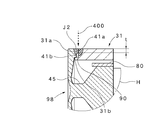
- FIG. 19 is a cross-sectional view of an injector unit 506B equipped with a combustion pressure sensor 508B
- FIG. 20 is an enlarged view of a region M in FIG.
- the combustion pressure sensor 508B according to the sixth embodiment is different from the combustion pressure sensor 508A according to the fifth embodiment described above (FIGS. 17 and 18).
- the protrusion 514c In the case of the combustion pressure sensor 508B, the protrusion 514c. It is in the point provided in.
- the protruding portions 514c are respectively provided on the pressure receiving ring block 514B side. It is provided.
- the combustion pressure sensor 508B according to the sixth embodiment is provided with the relief portions 90 ... similar to the combustion pressure sensor 508A according to the fifth embodiment, the same effect as the combustion pressure sensor 508A according to the fifth embodiment is obtained. Can do. Since the other basic configuration is the same as that of the fifth embodiment, the same parts and the same components are denoted by the same reference numerals, and a part of overlapping description is omitted. The same number is assigned to the same part and the same component, and the alphabet “B” attached to the number indicates the sixth embodiment. Incidentally, in Example 5, “A” is attached.
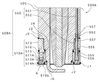
- FIG. 21 is a cross-sectional view of a spark plug 505 (a spark plug unit 509A) equipped with a combustion pressure sensor 508A
- FIG. 22 is an enlarged view of a region K in FIG.
- the difference between the combustion pressure sensor 508A according to the seventh embodiment and the combustion pressure sensor 508A according to the fifth embodiment (FIGS. 17 and 18) is that the combustion pressure sensor 508A is provided in the spark plug 505 in the seventh embodiment.
- a spark plug 505 is used as a functional component instead of the injector 507, and the shape of the joint with the pressure detection unit 510A differs depending on the shape of the spark plug 505.
- the basic configuration is the same.
- the combustion pressure sensor 508A according to the seventh embodiment is also provided with the same relief portion 90 ... as the combustion pressure sensor 508A according to the fifth embodiment described above, even if the target to which the combustion pressure sensor 508A is mounted is different, The same effects as those of the combustion pressure sensor 508A according to the fifth embodiment can be obtained. Since the other basic configuration is the same as that of the fifth embodiment, the same parts and the same components are denoted by the same reference numerals, and a part of overlapping description is omitted.
- the combustion pressure sensors 508A and 508B are mounted on the injector 507 and the spark plug 506, respectively, so that the injector unit 506A and the spark plug unit 509A are configured. Even when the combustion pressure sensors 508A... Are mounted on various functional parts such as a glow plug, they can be similarly implemented by providing similar relief portions 90. Note that the protrusions 511b and 512b may be provided on the pressure receiving ring block 514A side.
- the relief part (90 %) illustrated the case where it provided by the level
- this step part (41b %) was illustrated.
- various shapes can be applied as long as the effects of the present invention are achieved, such as a rectangular shape including a trapezoid, an arc shape, a triangular shape, and the like.
- various shapes can be applied to the shape and size of the protrusions (31b%) As long as the effects of the present invention are achieved.
- the combustion pressure sensor and the manufacturing method thereof according to the present invention can be widely used for detecting various combustion pressures including the combustion pressure in an internal combustion engine. Further, the combustion pressure sensor may be used alone, or may be used by being mounted on various functional parts such as an injector, a spark plug, and a glow plug.
Landscapes
- Physics & Mathematics (AREA)
- Engineering & Computer Science (AREA)
- General Physics & Mathematics (AREA)
- Chemical & Material Sciences (AREA)
- Combustion & Propulsion (AREA)
- Optics & Photonics (AREA)
- Mechanical Engineering (AREA)
- Plasma & Fusion (AREA)
- General Engineering & Computer Science (AREA)
- Measuring Fluid Pressure (AREA)
Abstract
Priority Applications (4)
| Application Number | Priority Date | Filing Date | Title |
|---|---|---|---|
| JP2016510428A JP6605449B2 (ja) | 2014-03-27 | 2015-03-25 | 燃焼圧センサ及びその製造方法 |
| EP15770334.9A EP3124941B1 (fr) | 2014-03-27 | 2015-03-25 | Capteur de pression de combustion et son procédé de fabrication |
| CN201580016807.7A CN106415229B (zh) | 2014-03-27 | 2015-03-25 | 燃烧压力传感器及其制造方法 |
| US15/129,598 US10458328B2 (en) | 2014-03-27 | 2015-03-25 | Welded combustion pressure sensor and method of manufacturing same |
Applications Claiming Priority (2)
| Application Number | Priority Date | Filing Date | Title |
|---|---|---|---|
| JP2014-067066 | 2014-03-27 | ||
| JP2014067066 | 2014-03-27 |
Publications (1)
| Publication Number | Publication Date |
|---|---|
| WO2015147061A1 true WO2015147061A1 (fr) | 2015-10-01 |
Family
ID=54195572
Family Applications (1)
| Application Number | Title | Priority Date | Filing Date |
|---|---|---|---|
| PCT/JP2015/059137 Ceased WO2015147061A1 (fr) | 2014-03-27 | 2015-03-25 | Capteur de pression de combustion et son procédé de fabrication |
Country Status (5)
| Country | Link |
|---|---|
| US (1) | US10458328B2 (fr) |
| EP (1) | EP3124941B1 (fr) |
| JP (1) | JP6605449B2 (fr) |
| CN (1) | CN106415229B (fr) |
| WO (1) | WO2015147061A1 (fr) |
Cited By (3)
| Publication number | Priority date | Publication date | Assignee | Title |
|---|---|---|---|---|
| CN107478380A (zh) * | 2016-06-07 | 2017-12-15 | 皮埃佐克莱斯特先进传感器有限公司 | 用于测量高压力的压电式压力传感器 |
| JP2018105715A (ja) * | 2016-12-26 | 2018-07-05 | シチズンファインデバイス株式会社 | 圧力検出装置の製造方法および圧力検出装置 |
| US11624669B2 (en) | 2016-08-17 | 2023-04-11 | Kistler Holding Ag | Pressure sensor for high pressures |
Families Citing this family (4)
| Publication number | Priority date | Publication date | Assignee | Title |
|---|---|---|---|---|
| DK3124943T3 (da) * | 2015-07-31 | 2021-08-30 | Kistler Holding Ag | Piezoelektrisk tryksensor og fremgangsmåde til fremstilling af den piezoelektriske tryksensor |
| EP3421961B1 (fr) * | 2016-02-25 | 2022-07-27 | Citizen Finedevice Co., Ltd. | Dispositif de détection de pression et système de détection de pression |
| CN112304486A (zh) * | 2020-11-17 | 2021-02-02 | 赛若麦得(上海)生物技术有限公司 | 一种管路压力监测装置 |
| CN115266883B (zh) * | 2022-06-22 | 2023-05-12 | 安徽科技学院 | 一种基于tfet器件的生物传感器及其制作方法 |
Citations (4)
| Publication number | Priority date | Publication date | Assignee | Title |
|---|---|---|---|---|
| JPS62168685A (ja) * | 1986-01-20 | 1987-07-24 | Kyowa Electronic Instr Corp Ltd | 溶接構造物 |
| JP2006308223A (ja) * | 2005-04-28 | 2006-11-09 | Ngk Spark Plug Co Ltd | 燃焼圧検知センサ付きグロープラグ |
| WO2013003965A1 (fr) * | 2011-07-07 | 2013-01-10 | Kistler Holding Ag | Procédé pour relier une membrane à un boîtier de capteur |
| WO2013147260A1 (fr) * | 2012-03-29 | 2013-10-03 | シチズンファインテックミヨタ株式会社 | Dispositif de détection de la pression, et moteur à combustion interne doté du dispositif de détection de la pression |
Family Cites Families (13)
| Publication number | Priority date | Publication date | Assignee | Title |
|---|---|---|---|---|
| US3461327A (en) * | 1965-12-09 | 1969-08-12 | List Hans | Piezoelectric pressure transducer |
| JP3476199B2 (ja) * | 1995-04-28 | 2003-12-10 | ローズマウント インコーポレイテッド | 高圧隔離マウント組立体を有する圧力トランスミッタ |
| CN2470813Y (zh) * | 2001-03-22 | 2002-01-09 | 孔载明 | 膜片式压力表膜片与壳体结构组件 |
| ATE470138T1 (de) * | 2004-01-30 | 2010-06-15 | Danfoss As | Druckmittler |
| JP2008064529A (ja) * | 2006-09-06 | 2008-03-21 | Denso Corp | 圧力センサ |
| AT504485B1 (de) * | 2006-11-22 | 2008-06-15 | Piezocryst Advanced Sensorics | Piezoelektrischer drucksensor |
| JP2010019828A (ja) * | 2008-06-11 | 2010-01-28 | Epson Toyocom Corp | 圧力センサー用ダイアフラムおよび圧力センサー |
| JP2010096656A (ja) * | 2008-10-17 | 2010-04-30 | Denso Corp | 圧力センサ |
| JP5234185B2 (ja) * | 2010-01-22 | 2013-07-10 | トヨタ自動車株式会社 | 溶接構造および溶接方法 |
| CN202013258U (zh) * | 2011-01-27 | 2011-10-19 | 杭州吉星仪表机械有限公司 | 膜片式灭火器压力显示器 |
| US9619495B2 (en) * | 2011-07-01 | 2017-04-11 | Hewlett Packard Enterprise Development Lp | Surrogate key generation |
| CN202210010U (zh) * | 2011-09-28 | 2012-05-02 | 杭州吉星仪表机械有限公司 | 具有非金属和金属组合式表壳的膜片式压力表 |
| JP5983493B2 (ja) * | 2013-03-26 | 2016-08-31 | 株式会社デンソー | 圧力センサ |
-
2015
- 2015-03-25 WO PCT/JP2015/059137 patent/WO2015147061A1/fr not_active Ceased
- 2015-03-25 US US15/129,598 patent/US10458328B2/en active Active
- 2015-03-25 JP JP2016510428A patent/JP6605449B2/ja active Active
- 2015-03-25 CN CN201580016807.7A patent/CN106415229B/zh active Active
- 2015-03-25 EP EP15770334.9A patent/EP3124941B1/fr active Active
Patent Citations (4)
| Publication number | Priority date | Publication date | Assignee | Title |
|---|---|---|---|---|
| JPS62168685A (ja) * | 1986-01-20 | 1987-07-24 | Kyowa Electronic Instr Corp Ltd | 溶接構造物 |
| JP2006308223A (ja) * | 2005-04-28 | 2006-11-09 | Ngk Spark Plug Co Ltd | 燃焼圧検知センサ付きグロープラグ |
| WO2013003965A1 (fr) * | 2011-07-07 | 2013-01-10 | Kistler Holding Ag | Procédé pour relier une membrane à un boîtier de capteur |
| WO2013147260A1 (fr) * | 2012-03-29 | 2013-10-03 | シチズンファインテックミヨタ株式会社 | Dispositif de détection de la pression, et moteur à combustion interne doté du dispositif de détection de la pression |
Non-Patent Citations (1)
| Title |
|---|
| See also references of EP3124941A4 * |
Cited By (5)
| Publication number | Priority date | Publication date | Assignee | Title |
|---|---|---|---|---|
| CN107478380A (zh) * | 2016-06-07 | 2017-12-15 | 皮埃佐克莱斯特先进传感器有限公司 | 用于测量高压力的压电式压力传感器 |
| CN107478380B (zh) * | 2016-06-07 | 2021-06-29 | 皮埃佐克莱斯特先进传感器有限公司 | 用于测量高压力的压电式压力传感器 |
| US11624669B2 (en) | 2016-08-17 | 2023-04-11 | Kistler Holding Ag | Pressure sensor for high pressures |
| EP3285057B1 (fr) * | 2016-08-17 | 2023-06-07 | Kistler Holding AG | Capteur de pression élevée |
| JP2018105715A (ja) * | 2016-12-26 | 2018-07-05 | シチズンファインデバイス株式会社 | 圧力検出装置の製造方法および圧力検出装置 |
Also Published As
| Publication number | Publication date |
|---|---|
| CN106415229A (zh) | 2017-02-15 |
| EP3124941A1 (fr) | 2017-02-01 |
| JP6605449B2 (ja) | 2019-11-13 |
| JPWO2015147061A1 (ja) | 2017-04-13 |
| CN106415229B (zh) | 2020-06-30 |
| US20170130650A1 (en) | 2017-05-11 |
| EP3124941A4 (fr) | 2017-11-01 |
| EP3124941B1 (fr) | 2021-09-01 |
| US10458328B2 (en) | 2019-10-29 |
Similar Documents
| Publication | Publication Date | Title |
|---|---|---|
| JP6605449B2 (ja) | 燃焼圧センサ及びその製造方法 | |
| US6973820B2 (en) | Combustion pressure sensor designed to ensure stability of output characteristic and sensitivity | |
| JP5975793B2 (ja) | 燃焼圧センサ | |
| CN104169702B (zh) | 带有燃烧压力检测装置的内燃机 | |
| JP6066767B2 (ja) | 内燃機関用燃焼圧センサ及びその製造方法。 | |
| JP5820759B2 (ja) | 圧力検出装置の製造方法、圧力検出装置付き内燃機関の製造方法 | |
| WO2013147260A1 (fr) | Dispositif de détection de la pression, et moteur à combustion interne doté du dispositif de détection de la pression | |
| US10221782B2 (en) | In-cylinder pressure detecting apparatus | |
| WO2013129483A1 (fr) | Dispositif de détection de la pression de combustion, et moteur à combustion interne équipé d'un dispositif de détection de la pression de combustion | |
| JP5978073B2 (ja) | 燃焼圧センサ | |
| JP6286355B2 (ja) | 内燃機関用燃焼圧センサ付き機能部品ユニット | |
| JP6013684B2 (ja) | 燃焼圧検知センサ付きセラミックグロープラグ | |
| JP6404455B2 (ja) | 燃焼圧センサ | |
| JP2013174553A (ja) | 圧力検出装置、圧力検出装置付き内燃機関 | |
| US20220329049A1 (en) | Spark plug and method for producing a spark plug | |
| JP2014070952A (ja) | 燃焼圧センサ | |
| JP2013195163A (ja) | 燃焼圧検出装置付き内燃機関および燃焼圧検出装置 | |
| JP5883691B2 (ja) | 燃焼圧検出装置付き内燃機関 | |
| JP6937148B2 (ja) | 圧力検出装置、圧力検出装置の製造方法 | |
| HK1204047B (en) | Internal combustion engine fitted with combustion pressure detection device | |
| JP2018084561A (ja) | 圧力検出装置および圧力検出装置付き内燃機関 |
Legal Events
| Date | Code | Title | Description |
|---|---|---|---|
| 121 | Ep: the epo has been informed by wipo that ep was designated in this application |
Ref document number: 15770334 Country of ref document: EP Kind code of ref document: A1 |
|
| ENP | Entry into the national phase |
Ref document number: 2016510428 Country of ref document: JP Kind code of ref document: A |
|
| NENP | Non-entry into the national phase |
Ref country code: DE |
|
| WWE | Wipo information: entry into national phase |
Ref document number: 15129598 Country of ref document: US |
|
| REEP | Request for entry into the european phase |
Ref document number: 2015770334 Country of ref document: EP |
|
| WWE | Wipo information: entry into national phase |
Ref document number: 2015770334 Country of ref document: EP |