WO2015147262A1 - 塗布装置、重ね給紙装置、積層体製造設備、塗布体の製造方法、及び積層体の製造方法 - Google Patents
塗布装置、重ね給紙装置、積層体製造設備、塗布体の製造方法、及び積層体の製造方法 Download PDFInfo
- Publication number
- WO2015147262A1 WO2015147262A1 PCT/JP2015/059626 JP2015059626W WO2015147262A1 WO 2015147262 A1 WO2015147262 A1 WO 2015147262A1 JP 2015059626 W JP2015059626 W JP 2015059626W WO 2015147262 A1 WO2015147262 A1 WO 2015147262A1
- Authority
- WO
- WIPO (PCT)
- Prior art keywords
- sheet
- coating
- roll
- coating agent
- application
- Prior art date
- Legal status (The legal status is an assumption and is not a legal conclusion. Google has not performed a legal analysis and makes no representation as to the accuracy of the status listed.)
- Ceased
Links
Images







Classifications
-
- B—PERFORMING OPERATIONS; TRANSPORTING
- B32—LAYERED PRODUCTS
- B32B—LAYERED PRODUCTS, i.e. PRODUCTS BUILT-UP OF STRATA OF FLAT OR NON-FLAT, e.g. CELLULAR OR HONEYCOMB, FORM
- B32B37/00—Methods or apparatus for laminating, e.g. by curing or by ultrasonic bonding
- B32B37/14—Methods or apparatus for laminating, e.g. by curing or by ultrasonic bonding characterised by the properties of the layers
- B32B37/16—Methods or apparatus for laminating, e.g. by curing or by ultrasonic bonding characterised by the properties of the layers with all layers existing as coherent layers before laminating
- B32B37/18—Methods or apparatus for laminating, e.g. by curing or by ultrasonic bonding characterised by the properties of the layers with all layers existing as coherent layers before laminating involving the assembly of discrete sheets or panels only
- B32B37/182—Methods or apparatus for laminating, e.g. by curing or by ultrasonic bonding characterised by the properties of the layers with all layers existing as coherent layers before laminating involving the assembly of discrete sheets or panels only one or more of the layers being plastic
-
- B—PERFORMING OPERATIONS; TRANSPORTING
- B05—SPRAYING OR ATOMISING IN GENERAL; APPLYING FLUENT MATERIALS TO SURFACES, IN GENERAL
- B05C—APPARATUS FOR APPLYING FLUENT MATERIALS TO SURFACES, IN GENERAL
- B05C1/00—Apparatus in which liquid or other fluent material is applied to the surface of the work by contact with a member carrying the liquid or other fluent material, e.g. a porous member loaded with a liquid to be applied as a coating
- B05C1/04—Apparatus in which liquid or other fluent material is applied to the surface of the work by contact with a member carrying the liquid or other fluent material, e.g. a porous member loaded with a liquid to be applied as a coating for applying liquid or other fluent material to work of indefinite length
- B05C1/08—Apparatus in which liquid or other fluent material is applied to the surface of the work by contact with a member carrying the liquid or other fluent material, e.g. a porous member loaded with a liquid to be applied as a coating for applying liquid or other fluent material to work of indefinite length using a roller or other rotating member which contacts the work along a generating line
- B05C1/0808—Details thereof, e.g. surface characteristics
-
- B—PERFORMING OPERATIONS; TRANSPORTING
- B05—SPRAYING OR ATOMISING IN GENERAL; APPLYING FLUENT MATERIALS TO SURFACES, IN GENERAL
- B05C—APPARATUS FOR APPLYING FLUENT MATERIALS TO SURFACES, IN GENERAL
- B05C1/00—Apparatus in which liquid or other fluent material is applied to the surface of the work by contact with a member carrying the liquid or other fluent material, e.g. a porous member loaded with a liquid to be applied as a coating
- B05C1/04—Apparatus in which liquid or other fluent material is applied to the surface of the work by contact with a member carrying the liquid or other fluent material, e.g. a porous member loaded with a liquid to be applied as a coating for applying liquid or other fluent material to work of indefinite length
- B05C1/08—Apparatus in which liquid or other fluent material is applied to the surface of the work by contact with a member carrying the liquid or other fluent material, e.g. a porous member loaded with a liquid to be applied as a coating for applying liquid or other fluent material to work of indefinite length using a roller or other rotating member which contacts the work along a generating line
- B05C1/0826—Apparatus in which liquid or other fluent material is applied to the surface of the work by contact with a member carrying the liquid or other fluent material, e.g. a porous member loaded with a liquid to be applied as a coating for applying liquid or other fluent material to work of indefinite length using a roller or other rotating member which contacts the work along a generating line the work being a web or sheets
- B05C1/083—Apparatus in which liquid or other fluent material is applied to the surface of the work by contact with a member carrying the liquid or other fluent material, e.g. a porous member loaded with a liquid to be applied as a coating for applying liquid or other fluent material to work of indefinite length using a roller or other rotating member which contacts the work along a generating line the work being a web or sheets being passed between the coating roller and one or more backing rollers
-
- B—PERFORMING OPERATIONS; TRANSPORTING
- B05—SPRAYING OR ATOMISING IN GENERAL; APPLYING FLUENT MATERIALS TO SURFACES, IN GENERAL
- B05C—APPARATUS FOR APPLYING FLUENT MATERIALS TO SURFACES, IN GENERAL
- B05C1/00—Apparatus in which liquid or other fluent material is applied to the surface of the work by contact with a member carrying the liquid or other fluent material, e.g. a porous member loaded with a liquid to be applied as a coating
- B05C1/04—Apparatus in which liquid or other fluent material is applied to the surface of the work by contact with a member carrying the liquid or other fluent material, e.g. a porous member loaded with a liquid to be applied as a coating for applying liquid or other fluent material to work of indefinite length
- B05C1/08—Apparatus in which liquid or other fluent material is applied to the surface of the work by contact with a member carrying the liquid or other fluent material, e.g. a porous member loaded with a liquid to be applied as a coating for applying liquid or other fluent material to work of indefinite length using a roller or other rotating member which contacts the work along a generating line
- B05C1/0826—Apparatus in which liquid or other fluent material is applied to the surface of the work by contact with a member carrying the liquid or other fluent material, e.g. a porous member loaded with a liquid to be applied as a coating for applying liquid or other fluent material to work of indefinite length using a roller or other rotating member which contacts the work along a generating line the work being a web or sheets
- B05C1/0834—Apparatus in which liquid or other fluent material is applied to the surface of the work by contact with a member carrying the liquid or other fluent material, e.g. a porous member loaded with a liquid to be applied as a coating for applying liquid or other fluent material to work of indefinite length using a roller or other rotating member which contacts the work along a generating line the work being a web or sheets the coating roller co-operating with other rollers, e.g. dosing, transfer rollers
-
- B—PERFORMING OPERATIONS; TRANSPORTING
- B05—SPRAYING OR ATOMISING IN GENERAL; APPLYING FLUENT MATERIALS TO SURFACES, IN GENERAL
- B05D—PROCESSES FOR APPLYING FLUENT MATERIALS TO SURFACES, IN GENERAL
- B05D1/00—Processes for applying liquids or other fluent materials
- B05D1/28—Processes for applying liquids or other fluent materials performed by transfer from the surfaces of elements carrying the liquid or other fluent material, e.g. brushes, pads, rollers
-
- B—PERFORMING OPERATIONS; TRANSPORTING
- B05—SPRAYING OR ATOMISING IN GENERAL; APPLYING FLUENT MATERIALS TO SURFACES, IN GENERAL
- B05D—PROCESSES FOR APPLYING FLUENT MATERIALS TO SURFACES, IN GENERAL
- B05D2252/00—Sheets
-
- B—PERFORMING OPERATIONS; TRANSPORTING
- B32—LAYERED PRODUCTS
- B32B—LAYERED PRODUCTS, i.e. PRODUCTS BUILT-UP OF STRATA OF FLAT OR NON-FLAT, e.g. CELLULAR OR HONEYCOMB, FORM
- B32B2317/00—Animal or vegetable based
- B32B2317/12—Paper, e.g. cardboard
-
- B—PERFORMING OPERATIONS; TRANSPORTING
- B32—LAYERED PRODUCTS
- B32B—LAYERED PRODUCTS, i.e. PRODUCTS BUILT-UP OF STRATA OF FLAT OR NON-FLAT, e.g. CELLULAR OR HONEYCOMB, FORM
- B32B2451/00—Decorative or ornamental articles
-
- B—PERFORMING OPERATIONS; TRANSPORTING
- B65—CONVEYING; PACKING; STORING; HANDLING THIN OR FILAMENTARY MATERIAL
- B65H—HANDLING THIN OR FILAMENTARY MATERIAL, e.g. SHEETS, WEBS, CABLES
- B65H5/00—Feeding articles separated from piles; Feeding articles to machines
- B65H5/24—Feeding articles in overlapping streams, i.e. by separation of articles from a pile
Definitions
- the present invention relates to a coating apparatus, a stack feeding apparatus, a laminate manufacturing facility, a manufacturing method of a coating body, and a manufacturing method of a stack.
- a laminate in which a laminating film is bonded to a sheet is known.
- an adhesive is applied to a plurality of partially overlapped sheets (herein referred to as single sheets) using a direct coater. After that, a laminating film is bonded to the sheet. According to such a laminating method, a laminate can be easily produced.
- the surface of the adhesive applied to the sheet using a direct coater has a line extending in the direction of rotation of the direct coater (the sheet conveying direction). Will occur. This streak is thought to originate from the stringing of the adhesive. Even if the laminating film is bonded to the sheet with the streaks remaining, air remains between the sheet and the laminating film. This streak remains even after solidification by the adhesive proceeds. As described above, when an adhesive is applied to a single-wafer sheet using a direct coater, the appearance defect due to the stripes of the adhesive finally becomes a problem.
- the present invention intends to provide a coating apparatus, a stack feeding apparatus, a laminate manufacturing facility, a manufacturing method of a coating body, and a manufacturing method of a stack.
- the coating apparatus of the present invention is located on one side of a sheet conveyance path and coats the backup roll that supports the sheet and the sheet that is positioned on the other side of the conveyance path and supported by the backup roll.
- the relative positions of the backup roll and the coating roll are changed between a coating roll for applying the agent, an applicationable position where the coating agent can be applied to the sheet, and a retracted position retracted from the applicationable position.
- a position change controller for performing the above.
- At least one of the backup roll and the coating roll has an urging means for urging in a direction in which a gap between the backup roll and the coating roll is narrowed.
- An application execution area in which the coating agent is applied by the coating roll is set in the conveyance path, and includes a sheet determination device that determines the presence or absence of the sheet upstream of the application execution area, and the sheet determination
- the apparatus determines that the sheet is present, the relative position is the application possible position, and when the sheet determination apparatus determines that the sheet is not present, the relative position is the retracted position. Is preferred.
- the coating apparatus of the present invention is located on one side of a sheet conveyance path and coats the backup roll that supports the sheet and the sheet that is positioned on the other side of the conveyance path and supported by the backup roll.
- a coating roll for applying the agent, a sheet in the conveyance path as a reference sheet, a sheet positioned upstream of the reference sheet in the conveyance path, an upstream sheet, the reference sheet and the upstream side When the partially overlapped state is defined as a partially overlapped state, the coating roll applies the coating agent to the reference sheet and the upstream sheet in the partially overlapped state.
- a mask member that is disposed between the coating roll and the conveyance path and blocks application of the coating agent to the sheet by the coating roll.
- the coating apparatus of the present invention is located on one side of a sheet conveyance path and coats the backup roll that supports the sheet and the sheet that is positioned on the other side of the conveyance path and supported by the backup roll.
- the mask member blocks application of the coating agent to the side portion in the width direction of the sheet.
- An overlapping sheet feeding device includes a sheet feeding device that feeds the sheet toward a sheet conveyance path, a sheet locking execution position that can lock the sheet fed from the sheet feeding device, and the sheet.
- a movable sheet locking tool between the unlocked sheet locking positions, and a mechanism for moving the sheet locking tool between the sheet locking execution position and the sheet locking releasing position.
- a stopper moving mechanism a sheet in the conveyance path as a reference sheet, a sheet positioned on the upstream side of the conveyance path from the reference sheet, an upstream sheet, and the reference sheet and the upstream sheet
- the locking tool moving mechanism switches between executing and releasing the locking so as to create the partially overlapped state.
- the sheet fastener is in a position deviated et or formed openings in the sheet, and performing the execution of the locking.
- the sheet locking tool at the sheet locking execution position may be positioned on a movement path of a side portion of the sheet in the width direction. preferable.
- the opening is positioned at the sheet locking position.
- the sheet locking tool is positioned at the sheet locking release position, and when the opening is removed from the sheet locking position, the sheet locking tool is positioned at the sheet locking execution position. It is preferable to do.
- the laminated body manufacturing equipment of the present invention includes a laminating apparatus for bonding a plurality of sheets in a partially overlapping state, and a plurality of sheets in a partially overlapping state.
- a separating device that cuts the film on which the sheets are bonded and separates the plurality of sheets into separate bodies while the films are bonded to each other, the laminating device and the separating device transporting the sheets Lined in this order from upstream to downstream in the path, the sheet is formed with a sheet opening, and the film closes the sheet opening.
- the plurality of sheets in the partially overlapping state are defined as an upstream sheet and a downstream sheet as a sheet positioned on the upstream side of the plurality of sheets, respectively. It is preferable that the upstream part of the downstream sheet is located above the downstream part of the upstream sheet.
- the apparatus further comprises a coating device that applies a coating agent to the plurality of partially overlapping sheets, and the coating device is located on one side of the sheet conveyance path and supports the sheet; and It is preferable to have a coating roll that is located on the other side of the conveyance path and that applies a coating agent to the sheet that is supported by the backup roll.
- the coating device is disposed upstream of the laminating device in the transport path.
- the backup roll rotates in the sheet conveying direction
- the coating roll rotates in the direction opposite to the sheet conveying direction
- the coating roll preferably has a groove for holding the coating agent.
- the coating agent supply device further supplies the coating agent to the coating roll, and the coating agent supply device includes a chamber portion in which the coating agent is accommodated, a chamber opening formed in the chamber portion, It is preferable to have.
- the manufacturing method of the coated body of the present invention includes: a sheet transporting process for transporting the sheet in a sheet transport path; and a coating agent carried on a coating roll on the sheet transported while being supported by a backup roll. And a relative position of the backup roll and the coating roll is between an application possible position where the coating agent can be applied to the sheet and a retracted position retracted from the application possible position.
- the relative position is the application possible position, and when the application process is not performed, the relative position is the retracted position.
- the manufacturing method of the coated body of the present invention includes: a sheet transporting process for transporting the sheet in a sheet transport path; and a coating agent carried on a coating roll on the sheet transported while being supported by a backup roll. And an application execution area where application of the coating agent is performed by the coating roll is set in the transport path, and the relative position between the backup roll and the coating roll is It is possible to switch between a position where the coating agent can be applied to the sheet and a retreat position where the coating agent is retracted from the position where the coating can be applied, and the presence / absence of the sheet is determined upstream of the application execution area. In the sheet determination step and the sheet determination step, the application If it is determined that the sheet is not in the upstream side of the row area, and wherein the relative position between the backup roll and the coating roll is in the retracted position.
- a mask step that is performed together with the coating step, and that masks transfer of the coating agent from the coating roll to the sheet, using a mask member disposed between the coating roll and the transport path. Is preferred.
- the manufacturing method of the coated body of the present invention includes: a sheet transporting process for transporting the sheet in a sheet transport path; and a coating agent carried on a coating roll on the sheet transported while being supported by a backup roll.
- An application step wherein the sheet in the conveyance path is a reference sheet, the sheet located upstream of the reference sheet in the conveyance path is an upstream sheet, and the reference sheet and the upstream sheet are partially
- the coating roll applies a coating agent to the reference sheet and the upstream sheet in the partially overlapped state in the applying step.
- the manufacturing method of the coated body of the present invention includes: a sheet transporting process for transporting the sheet in a sheet transport path; and a coating agent carried on a coating roll on the sheet transported while being supported by a backup roll.
- a masking step that is performed together with the coating step, and that masks transfer of the coating agent from the coating roll to the sheet using a mask member disposed between the coating roll and the transport path;
- the relative position between the backup roll and the coating roll, which is performed prior to the coating step and the masking step is defined as the position where the coating agent can be applied to the sheet and the position where the coating can be applied.
- Relative position switching that switches between the retracted position and the retracted position
- the backup roll and the coating roll are arranged so that the coating roll abuts between the first fixed portion and the second fixed portion of the mask member.
- the relative position is switched from the retracted position to the application possible position.
- the method for producing a laminate of the present invention includes a laminating step of bonding a strip-shaped film to the plurality of sheets in order to connect a plurality of partially overlapping sheets that are partially overlapped, and the partially overlapping state Separating the plurality of sheets bonded to each other, and separating the plurality of sheets into separate bodies while the films are bonded to each other.
- the opening formed in the sheet is provided.
- the film is bonded to the plurality of sheets so as to be closed by the film.
- an application step of applying a coating agent to the plurality of sheets in the partially overlapping state Prior to the laminating step, it is preferable to further include an application step of applying a coating agent to the plurality of sheets in the partially overlapping state.
- the downstream sheet of the plurality of sheets is defined as downstream of the upstream sheet. It is preferred that the upstream portion of the downstream seat is located above the portion.
- the plurality of sheets are conveyed while being supported from one side using a backup roll that rotates in the conveyance direction of the plurality of sheets, and rotated in the direction opposite to the conveyance direction of the plurality of sheets. It is preferable that the coating agent is applied to the other surface of the plurality of sheets in a transported state using a coating roll.
- the application step includes a first application step of supplying the coating agent to the rotating coating roll, and a second application of applying the coating agent held by the coating roll to the plurality of sheets. It is preferable to have a process.
- the film is preferably bonded to the display surface of the sheet.
- the manufacturing method of the coated body of the present invention includes: a sheet transporting process for transporting the sheet in a sheet transport path; and a coating agent carried on a coating roll on the sheet transported while being supported by a backup roll.
- An application step wherein a polishing material is applied to the surface of the wooden sheet in the application step.
- the manufacturing method of the coated body of the present invention includes: a sheet transporting process for transporting the sheet in a sheet transport path; and a coating agent carried on a coating roll on the sheet transported while being supported by a backup roll.
- An application process, and in the application process, a rust inhibitor is applied to the surface of the metal sheet.
- (A) is a perspective view which shows the outline
- (B) is a disassembled perspective view which shows the outline
- (A) is explanatory drawing which shows the outline
- (B) is explanatory drawing which shows the outline
- (C) is an explanatory view showing an outline of a partially overlapping state.
- FIG. 6 is a perspective view illustrating an outline of a partially overlapped sheet passing through an overlap sheet feeding device.
- A), (B) is a top view which shows the outline
- A) shows the case where the opening X is located at the sheet contact position Z, and
- FIG. 6 is a perspective view illustrating an outline of a sheet passing through an overlap sheet feeding device.
- the laminated body L includes a sheet S on which a design is applied by printing or the like, and a film F laminated on the sheet S.
- the film F has translucency, that is, is transparent or translucent. For this reason, in the laminated body L, the design applied to the sheet S can be visually recognized through the film F.
- Such a laminated body L is produced by bonding the film F on the surface of the sheet S (for example, a display surface on which a design is applied).
- the sheet S is, for example, paper
- the film F is, for example, a plastic film.
- the laminate manufacturing facility 2 is for making a laminate L (see FIG. 1), and includes a delivery device 10 that sends out a rectangular sheet S to the transport path R, and a transport path R.
- a sheet feeding device 20 that conveys the sheet S
- a coating device 30 that applies the adhesive C to the partially overlapped sheet S
- a drying device 40 that advances drying of the applied adhesive C
- a film F A sheet S with a film F (hereinafter referred to as a workpiece U) is obtained by laminating the sheets S in a partially overlapped state by bonding and obtaining a laminate T, and cutting the film F in the laminate T.
- the separation device 60 includes a stacking device 70 that performs a punching process on the workpiece U to obtain a stacked body L, and a control device 90 that controls each device.
- the conveyance path R in the laminate manufacturing facility 2 is formed by appropriately provided conveyance rollers or the like.
- the sending device 10 feeds the sheet S continuously or intermittently toward the transport path R, and stores the storage container 11 that stores the sheet S, and the sheet sending that feeds the sheet S from the storage container 11 to the transport path R.
- Machine 12 An example of the sheet feeder 12 is a pinch roll.
- the overlap sheet feeding device 20 includes a sheet locking tool 21 that can lock the sheet S moving on the conveyance path R, and a sheet that switches the posture of the sheet locking tool 21.
- a locking control unit 22 The overlap sheet feeding device 20 uses the sheet locking control unit 22 to perform a locking execution state (see FIG. 4A) in which locking with respect to the sheet S can be performed, and unlocking when the locking is released.
- the posture of the sheet locking tool 21 is switched between the states (see FIG. 4B).
- the sheet locking tool 21 is rotated to switch between the locking execution state (see FIG. 4A) and the locking release state (see FIG. 4B).
- the movement of the sheet locking tool 21 may be switched between the locking execution state (see FIG. 4A) and the locking release state (see FIG. 4B).
- the partially overlapped state of the sheets S refers to a sheet positioned on the upstream side of the transport path R with respect to the reference sheet S1 and the sheet on the transport path R.
- the upstream sheet S0 is defined, the reference sheet S1 and the upstream sheet S0 are partially overlapped.
- the coating device 30 is located on one side (lower side in the drawing) of the transport path R, and a backup roll 31 that supports the sheet S and a backup roll drive motor 31M that drives the backup roll 31.
- a coating roll 32 positioned on the other side (upper side in the drawing) of the transport path R, a coating roll drive motor 32M that drives the coating roll 32, an application unit 35 that supplies the adhesive C to the coating roll 32, Is provided.
- Each roll 31 and 32 is rotated by each motor 31M and 32M.
- the peripheral surface of the backup roll 31 in the vicinity of the conveyance path R moves in the same direction as the conveyance direction of the sheet S.
- the peripheral surface of the coating roll 32 in the vicinity of the conveyance path R moves in the direction opposite to the conveyance direction of the sheet S.
- the coating unit 35 includes a chamber 35C that stores the adhesive C, and a supply port 35X that supplies the adhesive C stored in the chamber 35C to the peripheral surface of the coating roll 32.
- the coating unit 35 is arranged so that the supply port 35 ⁇ / b> X is close to the peripheral surface of the coating roll 32.
- Examples of the application unit 35 include a doctor blade, and examples of the adhesive C include an aqueous synthetic resin emulsion.
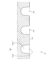
- a groove 32S that can be filled with the adhesive C is formed on the peripheral surface 32A of the coating roll 32 (FIG. 3B).
- the groove 32S is a structure for holding a sufficient amount of the adhesive C for application, and has a bottom 32SB and an opening 32SX.
- the opening 32SX is a structure for supplying the adhesive C filled therein to the sheet S, and the bottom 32SB does not use the excess adhesive C for application when applying the adhesive C to the sheet S.
- it is a structure for holding it as it is. Therefore, the application amount of the adhesive C on the sheet S is strongly influenced by the shape, size, formation density, and the like of the opening 32SX.
- the opening 32SX moves relative to the sheet S, so that a part of the adhesive C (or paint or coating agent) in the groove 32S is transferred to the sheet S through the opening 32SX. Very evenly spread.
- the adhesive C or paint, coating agent, rust inhibitor
- the plurality of openings 32SX are repeatedly formed on the surface of the sheet S. Therefore, the adhesive C (or paint, coating agent, rust inhibitor) can be sufficiently applied in the fine irregularities.
- the coating apparatus 30 includes a position change control unit 37 and a sheet determination unit 38.
- the position change controller 37 determines the position of the backup roll 31 between the application possible position where the adhesive C can be applied to the sheet S (see FIG. 3A) and the application retracted position retracted from the application possible position (see FIG. 5). Make changes.
- the backup roll 31 in the present embodiment can be moved in the vertical direction by the position change controller 37, is close to the transport path R at the application possible position (see FIG. 3A), and is away from the transport path R at the application retracted position. (See FIG. 5).
- the sheet determination device 38 is located in a determination area A0 (see FIG. 6) set on the upstream side in the conveyance direction from the application execution area A1 (see FIG. 6) where application is performed by the application device 30. It is determined whether or not the sheet S exists.
- At least one of the backup roll 31 and the coating roll 32 has an urging means for urging the gap between the backup roll 31 and the coating roll 32 in a narrowing direction.
- a spring, a pneumatic pressure or a hydraulic cylinder is used as the biasing means. As a result, a pinching pressure can be applied while minutely changing the interval between the backup roll 31 and the coating roll 32.
- the interval between the backup roll 31 and the coating roll 32 at the application possible position is set somewhat narrower than that of the sheet material S.
- an appropriate pressure is applied by the biasing means while absorbing the gap between the rolls and the thickness difference (error) of the sheet S.
- the sheet S is a wood having a certain thickness, a metal steel plate, a metal sheet (for example, an aluminum sheet) or the like
- an error may occur in the thickness between the plurality of sheets S.
- the coating apparatus 30 preferably further includes a mask unit 39.
- the mask unit 39 includes a mask member 39M disposed between the transport path R and the coating roll 32, and a mask fixing member 39F for fixing the mask member 39M.
- the mask fixing member 39F is provided on both the upstream side and the downstream side of the coating roll 32 in the transport direction.
- the mask member 39M is formed in a band shape, and is set between the fixed portion 39MA held by the upstream and downstream mask fixing members 39F and the fixed portion 39MA. And a contact portion 39MB in contact with the peripheral surface of the coating roll 32.
- the mask member 39M is arranged to extend in the conveyance direction of the sheet S.
- the drying device 40 is for evaporating a solvent (for example, water) from the adhesive C applied to the sheet S, and includes a dryer 41 that supplies a predetermined drying air to the adhesive C. Have.
- the dryer 41 is disposed on the other side of the transport path R.
- the laminating apparatus 50 forms a laminated body T in which a partially overlapped sheet S and a film F are integrated, a film sending machine 51 for feeding a belt-like film F, and a sheet S coated with an adhesive C.
- a crimping machine 52 for bonding the film F fed from the film delivery machine 51 is provided.
- the crimping machine 52 includes a receiving roll 52 ⁇ / b> B disposed on one side of the conveyance path R and a pressure roll 52 ⁇ / b> P disposed on the other side of the conveyance path R.
- the amount of pressurization of the pressure roll 52P toward the receiving roll 52B can be adjusted by a control unit (not shown).
- the separating device 60 includes a cutting machine 61 that cuts the film F and a cutting position setting machine 62 that sets the cutting position of the film F.
- the cutting position setting machine 62 sets a cutting position for the laminate T in which the partially overlapped sheet S and film F are integrated.
- the cutting position is preferably set at a position CP on the film F (see FIG. 7A).
- the position CP indicates a portion where a gap between the sheet S and the film F is formed.
- the cutting machine 61 cuts the film F at the cutting position.
- the laminated body T in which the partially overlapped sheet S and the film F are integrated by cutting the film F becomes a workpiece U in which the individual sheets S and the cut film F are integrated (see FIG. 7 (B)).
- the workpiece U includes a sheet S and a film F, and the edge of the sheet S projects beyond the film F.
- a portion (hereinafter, referred to as a protruding portion) V that protrudes from the film F of the sheet S has a structure for aligning the ends of the workpieces U in the stacking device 70.
- the loading device 70 includes an aligner 71 that overlaps the workpieces U so that the ends of the individual workpieces U are aligned.
- the aligner 71 includes a pedestal 71A on which the workpiece U is placed, a pinch roller 71B that feeds the workpiece U conveyed on the conveyance path R to the pedestal 71A, and an alignment member 71C provided on the pedestal 71A. And have.
- the alignment member 71C protrudes from the pedestal 71A and has a shape capable of coming into contact with a corner or an end of the workpiece U placed on the pedestal 71A. For this reason, the member U to be processed that is sequentially sent to the base 71A by the pinch roller 71B overlaps with the aligned member 71C in a state where the corners are aligned.
- a punching machine 72 that punches the workpiece U that overlaps with the corners aligned may be disposed on the downstream side of the stacking device 70. Thereby, the laminated body L (refer FIG. 1) is obtained from the to-be-processed member U.
- the punching machine 72 may be arranged continuously with respect to the loading device 70 (online arrangement), or may be arranged away from the loading apparatus 70 (offline arrangement).
- the position change controller 37 of the coating apparatus 30 moves the backup roll 31 away from the conveyance path R and the relative relationship between the roll 31 and the roll 32. Set the position to the application retracted position.
- the fixing portion 39MA of the mask member 39M is held by the mask fixing member 39F.
- the width W A1 of the application execution area A1 is determined by the width of the supply port 35X formed in the chamber 35C, here, as shown in FIG. 6, the two masks member 39M to align in the width direction sides of the transport path R, the width W A1 of the application execution area A1 is narrower than in the case of not using the mask member 39M.
- the width direction of the transport path R is a direction orthogonal to the transport direction.
- the delivery device 10 sequentially sends out the sheets S to the conveyance path R (see FIG. 2).
- the sheet locking control unit 22 has a sheet locking tool 21 between the locking execution state (see FIG. 4A) and the locking release state (see FIG. 4B). Are switched at a predetermined timing. Accordingly, the plurality of sheets S sequentially sent out from the sending device 10 are partially overlapped and conveyed to the coating device 30.
- the sheet determination device 38 determines whether or not the sheet S exists in the determination area A0.
- the position change control unit 37 keeps the relative positions of the roll 31 and the roll 32 at the application retracted position (see FIG. 5).
- the position change controller 37 moves the backup roll 31 closer to the conveyance path R and sets the relative positions of the roll 31 and the roll 32. Then, the application switching position (see FIG. 5) is switched to the application possible position (see FIG. 3A).
- the rotation of the backup roll 31 moves the circumferential surface of the backup roll 31 in the application execution area A ⁇ b> 1 in the same direction as the conveyance direction of the sheet S, so the sheet S is conveyed in the conveyance direction.
- the peripheral surface of the coating roll 32 in the application execution area A ⁇ b> 1 moves in the direction opposite to the conveying direction of the sheet S.
- the coating unit 35 supplies the adhesive C to the rotating coating roll 32.
- the adhesive C coming out of the supply port 35X is filled in a groove formed on the peripheral surface of the coating roll 32, and approaches the transport path R by the rotation of the coating roll 32.
- the adhesive C filled in the groove of the coating roll 32 is transferred to the sheet S in the application execution area A1.
- a groove 32S that can be filled with the adhesive C is formed on the peripheral surface 32A of the coating roll 32, so that the adhesive C supplied from the coating unit 35 has a bottom 32SB and an opening 32SX. And both are filled.
- the adhesive C filled in the opening 32SX is transferred to the sheet S, but is filled in the bottom 32SB.
- the adhesive C is not transferred to the sheet S and remains filled in the bottom 32SB.
- the adhesive applied to the coating roll is applied to the sheet as it is.
- the amount applied to the coating roll (the thickness of the coating film) remains as it is of the sheet S. It will be thick. As a result, it is very difficult to perform thin coating (for example, the thickness of the coating film is 10 ⁇ m or less).
- the coating amount of the sheet S is likely to fluctuate depending on the rotation speed of the coating roll.
- the application amount of the adhesive C can be adjusted depending on the physical properties of the adhesive C, the formation density of the openings 32SX on the peripheral surface 32A, and the like.
- the formation density of the openings 32SX can be adjusted by the shape and formation density of the grooves 32S. Therefore, when the coating roll 32 having the grooves 32S is used, the adhesive C can be thinly applied to the sheet S more easily than the conventional one. Further, it is not necessary to control the coating roll 32 at a high rotational speed in order to adjust the coating amount on the sheet S.
- a predetermined drying air is supplied to the adhesive C applied to the partially overlapped sheet S. Thereby, the solvent can be evaporated from the adhesive C applied to the sheet S.
- the film sending machine 51 sends out the belt-like film F.
- the crimping machine 52 bonds the belt-like film F sent out from the film sending machine 51 to the sheet S coated with the adhesive C.
- a plurality of sheets S that are partially overlapped by bonding with the belt-like film F are continuous (see FIG. 7A). In this way, a laminate T in which the partially overlapping sheet S and the film F are integrated is obtained.
- the cutting machine 61 cuts the film F at the cutting position set by the cutting position setting machine 62.
- the laminated body T in which the partially overlapped sheet S and the film F are integrated by cutting the film F becomes a workpiece U in which the individual sheets S and the cut film F are integrated (see FIG. 7 (B)).
- the aligner 71 stacks the workpieces U so that the ends of the individual workpieces U are aligned (see FIG. 8).
- the punching machine 72 collectively performs the punching process on the plurality of workpieces U whose ends are aligned by the cutting machine 61.
- the laminated body L (refer FIG. 1) stamped by the desired shape can be obtained.
- the front side of each sheet S (the downstream side in the transport direction) is a protruding portion V that protrudes from the film F, so that the film F does not get in the way when the front ends of the sheets S are aligned.
- the upstream sheet S0 preferably overlaps the reference sheet S1 as an aspect of the partially overlapping sheet S.
- the rear side (upstream side in the conveyance direction) of each sheet S projects from the film F. Since the portion V is formed, the rear ends of the sheets S may be aligned.
- the adhesive C is applied to the partially overlapped sheet S using the coating roll 32 that moves in the direction opposite to the conveying direction of the sheet S (see FIG. 3A), uneven coating (for example, The adhesive C can be applied without generating the above-mentioned streaks of the adhesive C). For this reason, air does not remain between the sheet S and the film F in the partially overlapping state in the laminate T, and finally, in the laminate L, it is possible to suppress appearance defects due to the adhesive streaks.
- the backup roll 31 can be set to the application retreat position (see FIG. 5). For this reason, the adhesive C applied to the coating roll 32 is less likely to adhere to the backup roll 31.
- the gap CL1 see FIG. 3A
- the gap CL1 is 0.5 mm or less
- the position change control unit 37 and the sheet determination unit 38 are significant.
- the relative positions of the roll 31 and the roll 32 are switched by moving only the backup roll 31, but the present invention is not limited to this, and only the coating roll 32 is moved or both the rolls 31 and 32 are moved.
- the relative positions of the roll 31 and the roll 32 may be switched by the movement of.
- the adhesive C is not applied to the portion of the sheet S that passes through the application execution area A1 that does not directly contact the coating roll 32 by the mask member 39M.
- an extra adhesive is provided by placing the mask member 39M at a predetermined location. C is not applied to the sheet S.
- the surplus adhesive C does not protrude from the film F.
- the surplus adhesive does not adhere to the side in the width direction when the workpiece U is formed, the ends of the workpiece U can be accurately aligned (see FIG. 8). As a result, it is possible to perform punching alignment with high accuracy.
- an example of the adhesive C is an aqueous synthetic resin emulsion, but the present invention is not limited to this.
- an adhesive composition that does not contain an organic solvent such as an aqueous synthetic resin emulsion can be used as the adhesive C in terms of safety and environmental aspects.
- the water-based synthetic resin emulsion has a higher viscosity than other adhesive compositions. For this reason, when coating is performed using a normal coating apparatus (for example, a coating apparatus in which both the coating roll and the backup roll rotate in the same direction as the sheet S conveyance direction), stringing of the adhesive C occurs. End up.
- the coating roll 32 rotates in the direction opposite to the conveying direction of the sheet S as in the coating apparatus 30, even with the adhesive C having a high viscosity such as an aqueous synthetic resin emulsion, stringing occurs. Hateful. Therefore, by using the coating device 30, the adhesive C can be applied while preventing stringing regardless of the viscosity of the adhesive C.
- the laminate L is made using the sheet S in which no opening is formed.
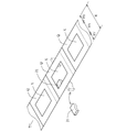
- the present invention is not limited to this, and the opening X is formed as shown in FIG.
- the laminated body M may be manufactured using the sheet
- the laminate M includes a sheet Q in which an opening X is formed, and a film F laminated on the sheet Q.
- Such a laminated body M can be manufactured in the laminated body manufacturing equipment 2 mentioned above.
- the sheet stoppers 21 are disposed at both ends of the conveyance path R in the width direction.
- the movement path of the opening X of the sheet Q in the conveyance path R is defined as the opening movement path RX
- the portions on both sides of the opening movement path RX in the conveyance path R are defined as the both-side movement path RY
- a portion where a certain sheet locking tool 21 (two-dot chain line in FIG. 10) is locked with the sheet Q is preferably located in the both-side movement path RY.
- the sheet locking tool 21 at the locking execution position does not have to be caught in the opening X of the sheet Q.
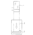
- a position where the sheet locking tool 21 in the sheet locking execution position (see FIG. 4A) and the sheet Q in the conveyance path R come into contact is defined as a sheet contact position Z (see FIGS. 4 and 11).
- the sheet locking tool 21 is positioned at the sheet locking release position (see FIG. 4B)
- the sheet engagement member 21 is positioned at the sheet engagement execution position (see FIG. 4 (A)). It is preferable that the stop control part 22 operates.
- the overlap feeding device 20 may further include an opening determination unit 26 (see FIG. 3A) that determines whether or not the opening X of the sheet Q exists at the sheet contact position Z. good.
- the sheet locking tool 21 may be moved in the width direction of the conveyance path R so that the sheet contact position Z deviates from the opening X based on the determination result of the opening determination unit 26. In the case where a plurality of sheet locking tools 21 are used, only the sheet locking tool 21 whose sheet contact position Z is out of the opening X may be moved to the sheet locking execution position (see FIG. 4A).
- the sheet locking at the sheet locking execution position may extend so as to cross the width direction of the transport path R (see FIG. 12).
- only the backup roll 31 is moved using the position change controller 37, but the present invention is not limited to this, and only the coating roll 32 may be moved, and the coating roll 32 and the backup roll may be moved. Both movements of the roll 31 may be performed.
- the mask member 39M is employed. However, when the application of the excessive adhesive C does not cause a problem, the mask member 39M may be omitted.
- the laminate obtained in this way can be used as a packaging container.
- a packaging container in which the sheet S is positioned on the outer surface or a packaging container in which the sheet S is positioned on the inner surface may be used.
- the design applied to the sheet S is located on the surface
- the appearance of the packaging container is improved.
- the film F is located on the outer surface
- the packaging container is less likely to adhere to dirt.
- the film F is located on the inner surface, it is possible to prevent leakage of the stored items (liquid, solid, etc.) and to prevent the stored items from being preserved and moisture-proof.
- the film F is transparent or translucent so that the design applied to the sheet S can be visually recognized.
- the present invention is not limited to this. That is, the film F may not be transparent or translucent.
- the sheet S is preferably used for wood having a certain thickness, a metal steel plate, a metal sheet (for example, an aluminum sheet), or the like.
- a sheet S having a thickness of 1 mm or more specifically, a sheet S having a thickness of 5 mm or more.
- a polishing coating on the surface of the wood sheet S.
- a rust preventive coating to the metal sheet S.
- the sheet S can be mass-produced on a roofing material or the like by deforming the sheet S with a press or the like and applying a paint.
Landscapes
- Coating Apparatus (AREA)
- Feeding Of Articles By Means Other Than Belts Or Rollers (AREA)
- Application Of Or Painting With Fluid Materials (AREA)
- Laminated Bodies (AREA)
Abstract
Description
前記上流シートの下流部分の上方に前記下流シートの上流部分が位置することが好ましい。
10 送出装置
20 給紙装置
21 シート係止具
22 シート係止制御部
26 開口判定機
30 塗布装置
31 バックアップロール
31M バックアップロール用駆動モータ
32 コーティングロール
32M コーティングロール用駆動モータ
35 塗布ユニット
35C チャンバ
35X 供給口
37 位置変更制御機
38 シート判定機
39 マスクユニット
39F マスク固定部材
39M マスク部材
39MA 固定部
39MB 接触部
40 乾燥装置
50 ラミネート装置
60 分離装置
70 加工装置
71 揃え機
71A 台座
71B ピンチローラ
71C 位置合わせ部材
72 打抜機
90 制御装置
A0 判定エリア
A1 塗布実行エリア
C 接着剤
CL1 隙間
F フィルム
L 積層体
M 積層体
Q シート
R 搬送路
RX 開口移動経路
RY 両側移動経路
S シート
S0 上流側シート
S1 基準シート
T ラミネート体
U 被加工部材
WA1 幅
X 開口
Z シート接触位置
Claims (30)
- シートの搬送路の一方側に位置し、前記シートを支持するバックアップロールと、
前記搬送路の他方側に位置し、前記バックアップロールに支持された状態の前記シートにコーティング剤を塗布するコーティングロールと、
前記シートに対する前記コーティング剤の塗布が可能な塗布可能位置、及び前記塗布可能位置から退避した退避位置の間で、前記バックアップロール及び前記コーティングロールの相対的位置の変更を行う位置変更制御機と、
を備えることを特徴とする塗布装置。 - 前記バックアップロール及び前記コーティングロールの少なくとも一方には、前記バックアップロール及び前記コーティングロールの隙間が狭くなる方向に付勢する付勢手段を有することを特徴とする請求の範囲1に記載の塗布装置。
- 前記搬送路には、前記コーティングロールによって前記コーティング剤の塗布が行われる塗布実行エリアが設定され、
前記塗布実行エリアよりも上流側において前記シートの有無を判定するシート判定装置を備え、
前記シート判定装置によって前記シートが有ると判定された場合、前記相対的位置は前記塗布可能位置であり、前記シート判定装置によって前記シートが無いと判定された場合、前記相対的位置は前記退避位置であることを特徴とする請求の範囲1又は2記載の塗布装置。 - シートの搬送路の一方側に位置し、前記シートを支持するバックアップロールと、
前記搬送路の他方側に位置し、前記バックアップロールに支持された状態の前記シートにコーティング剤を塗布するコーティングロールと、を備え、
前記搬送路にあるシートを基準シートと、前記基準シートよりも前記搬送路の上流側に位置するシートを上流側シートと、前記基準シート及び前記上流側シートが部分的に重なった状態を部分重なり状態と、それぞれ定義した際、
前記コーティングロールは、前記部分重なり状態の前記基準シート及び前記上流側シートに対して、前記コーティング剤を塗布することを特徴とする塗布装置。 - 前記コーティングロールと前記搬送路との間に配され、前記コーティングロールによる前記シートへの前記コーティング剤の塗布を遮るマスク部材をさらに備えることを特徴とする請求の範囲1ないし4のうちいずれか1項記載の塗布装置。
- シートの搬送路の一方側に位置し、前記シートを支持するバックアップロールと、
前記搬送路の他方側に位置し、前記バックアップロールに支持された状態の前記シートにコーティング剤を塗布するコーティングロールと、
前記コーティングロールと前記搬送路との間に配され、前記コーティングロールによる前記シートへの前記コーティング剤の塗布を遮るマスク部材と、
を備えることを特徴とする塗布装置。 - 前記シートの搬送方向に交差する方向を幅方向と定義した際、
前記マスク部材は、前記シートのうち前記幅方向の側部への前記コーティング剤の塗布を遮ることを特徴とする請求の範囲5または6項記載の塗布装置。 - シートの搬送路に向けて前記シートを送り出すシート送出装置と、
前記シート送出装置から送り出された前記シートに対する係止が可能なシート係止実行位置及び前記シートに対する係止が解除されたシート係止解除位置の間で、移動自在なシート係止具と、
前記シート係止実行位置及び前記シート係止解除位置の間で、前記シート係止具を移動させる係止具移動機構と、を備え、
前記搬送路にあるシートを基準シートと、前記基準シートよりも前記搬送路の上流側に位置するシートを上流側シートと、前記基準シート及び前記上流側シートが部分的に重なった状態を部分重なり状態と、それぞれ定義した際、
前記係止具移動機構は、前記部分重なり状態をつくるように、前記係止の実行及び解除の切り替えを行ない、
前記シート係止具は、前記シートに形成された開口から外れた位置において、前記係止の実行を行なうことを特徴とする重ね給紙装置。 - 前記シートの搬送方向に交差する方向を幅方向と定義した際、
前記シート係止実行位置にある前記シート係止具は、前記シートのうち前記幅方向の側部の移動経路に位置することを特徴とする請求の範囲8記載の重ね給紙装置。 - 前記シート係止実行位置にある前記シート係止具が、前記搬送路にある前記シートと係止する部分をシート係止位置と定義した際、
前記シート係止位置に前記開口が位置する場合には、前記シート係止具は前記シート係止解除位置に位置し、前記シート係止位置から前記開口が外れている場合には、前記シート係止具は前記シート係止実行位置に位置することを特徴とする請求の範囲8または9記載の重ね給紙装置。 - 一部が重なった部分重なり状態の複数のシートを連ねるために、前記複数のシートに対して帯状のフィルムを貼り合わせるラミネート装置と、
前記部分重なり状態の前記複数のシートが貼り合わされた前記フィルムの切断を行ない、前記複数のシートを前記フィルムが貼り合わされたまま別体に分離する分離装置と、を備え、
前記ラミネート装置と前記分離装置とは前記シートの搬送路において上流から下流に向けてこの順で並び、
前記シートにはシート開口が形成され、
前記フィルムは、前記シート開口を閉塞することを特徴とする積層体製造設備。 - 前記部分重なり状態の複数のシートは、前記複数のシートのうち、上流側に位置するシートを上流シートと、下流側に位置するシートを下流シートと、それぞれ定義した場合、
前記上流シートの下流部分の上方に前記下流シートの上流部分が位置することを特徴とする請求の範囲8ないし11のうちいずれか1項記載の積層体製造設備。 - 前記部分重なり状態の複数のシートに対し、コーティング剤を塗布する塗布装置をさらに備え、
前記塗布装置は、
前記シートの搬送路の一方側に位置し、前記シートを支持するバックアップロールと、
前記搬送路の他方側に位置し、前記バックアップロールに支持された状態の前記シートにコーティング剤を塗布するコーティングロールと、を有することを特徴とする請求の範囲11または12記載の積層体製造設備。 - 前記塗布装置は、前記搬送路において、前記ラミネート装置よりも上流側に配されることを特徴とする請求の範囲13記載の積層体製造設備。
- 前記バックアップロールは前記シートの搬送方向に回転し、
前記コーティングロールは前記シートの搬送方向と逆向きに回転することを特徴とする請求の範囲13または14記載の積層体製造設備。 - 前記コーティングロールは、前記コーティング剤を保持する溝を有することを特徴とする請求の範囲13ないし15のうちいずれか1項記載の積層体製造設備。
- 前記コーティングロールに対し前記コーティング剤を供給するコーティング剤供給装置をさらに備え、
前記コーティング剤供給装置は、
前記コーティング剤が収容されるチャンバ部と、
前記チャンバ部に形成されたチャンバ開口と、を有することを特徴とする請求の範囲13ないし15のうちいずれか1項記載の積層体製造設備。 - シートの搬送路において前記シートを搬送させるシート搬送工程と、
バックアップロールによって支持されながら搬送された前記シートに対し、コーティングロールに担持されたコーティング剤の塗布を行う塗布工程と、を備え、
前記バックアップロール及び前記コーティングロールの相対的位置は、前記シートに対する前記コーティング剤の塗布が可能な塗布可能位置と、前記塗布可能位置から退避した退避位置との間で切り替え自在であって、
前記塗布工程が行われる場合には前記相対的位置が前記塗布可能位置であり、
前記塗布工程が行われない場合には前記相対的位置が前記退避位置であることを特徴とする塗布体の製造方法。 - シートの搬送路において前記シートを搬送させるシート搬送工程と、
バックアップロールによって支持されながら搬送された前記シートに対し、コーティングロールに担持されたコーティング剤の塗布を行う塗布工程と、を備え、
前記搬送路には、前記コーティングロールによって前記コーティング剤の塗布が行われる塗布実行エリアが設定されるとともに、前記バックアップロールと前記コーティングロールとの相対的位置は、前記シートに対する前記コーティング剤の塗布が可能な塗布可能位置と、前記塗布可能位置から退避した退避位置との間で切り替え自在であって、
前記塗布実行エリアよりも上流側における前記シートの有無を判定するシート判定工程と、
前記シート判定工程において、前記塗布実行エリアよりも上流側に前記シートが無いと判定された場合、前記バックアップロールと前記コーティングロールとの相対的位置が前記退避位置であることを特徴とする塗布体の製造方法。 - 前記塗布工程とともに行われ、前記コーティングロールと前記搬送路との間に配されたマスク部材を用いて、前記コーティングロールから前記シートへの前記コーティング剤の転写を遮るマスク工程と、をさらに備えることを特徴とする請求の範囲18または19記載の塗布体の製造方法。
- シートの搬送路において前記シートを搬送させるシート搬送工程と、
バックアップロールによって支持されながら搬送された前記シートに対し、コーティングロールに担持されたコーティング剤の塗布を行う塗布工程と、を備え、
前記搬送路にあるシートを基準シートと、前記基準シートよりも前記搬送路の上流側に位置するシートを上流側シートと、前記基準シート及び前記上流側シートが部分的に重なった状態を部分重なり状態と、それぞれ定義した際、
前記塗布工程において、前記コーティングロールは、前記部分重なり状態の前記基準シート及び前記上流側シートに対してコーティング剤を塗布することを特徴とする塗布体の製造方法。 - シートの搬送路において前記シートを搬送させるシート搬送工程と、バックアップロールによって支持されながら搬送された前記シートに対し、コーティングロールに担持されたコーティング剤の塗布を行う塗布工程と、前記塗布工程とともに行われ、前記コーティングロールと前記搬送路との間に配されたマスク部材を用いて、前記コーティングロールから前記シートへの前記コーティング剤の転写を遮るマスク工程と、定義した際、
前記塗布工程及び前記マスク工程に先だって行われ、前記バックアップロールと前記コーティングロールとの相対的位置を、前記シートに対する前記コーティング剤の塗布が可能な塗布可能位置と前記塗布可能位置から退避した退避位置との間で切り替える相対的位置切替工程を備え、
前記相対的位置切替工程では、前記マスク部材のうち第1の固定部分と第2の固定部分との間に前記コーティングロールが当接するように、前記バックアップロールと前記コーティングロールとの相対的位置を前記退避位置から前記塗布可能位置へ切り替えることを特徴とする塗布体の製造方法。 - 一部が重なった部分重なり状態の複数のシートを連ねるために、前記複数のシートに対して帯状のフィルムを貼り合わせるラミネート工程と、
前記部分重なり状態の前記複数のシートが貼り合わされた前記フィルムの切断を行ない、前記複数のシートを前記フィルムが貼り合わされたまま別体に分離する分離工程と、を備え、
前記ラミネート工程では、前記シートに形成された開口が前記フィルムによって閉塞されるように、前記複数のシートに前記フィルムを貼り合わせることを特徴とする積層体の製造方法。 - 前記ラミネート工程に先だって、前記部分重なり状態の前記複数のシートに対しコーティング剤を塗布する塗布工程をさらに備えることを特徴とする請求の範囲23記載の積層体の製造方法。
- 前記部分重なり状態の複数のシートは、前記複数のシートのうち、上流側に位置するシートを上流シートと、下流側に位置するシートを下流シートと、それぞれ定義した場合、
上流シートの下流部分の上方に下流シートの上流部分が位置することを特徴とする請求の範囲18または24記載の積層体の製造方法。 - 前記塗布工程では、
前記複数のシートの搬送方向に回転するバックアップロールを用いて、前記複数のシートを一方側から支持しながら搬送するとともに、
前記複数のシートの搬送方向と逆向きに回転するコーティングロールを用いて、搬送状態の前記複数のシートの他方側の面に対する前記コーティング剤の塗布を行うことを特徴とする請求の範囲25記載の積層体の製造方法。 - 前記塗布工程は、
回転状態の前記コーティングロールに対し前記コーティング剤を供給する第1塗布工程と、
前記コーティングロールによって保持された前記コーティング剤を、前記複数のシートへ塗布する第2塗布工程と、を有することを特徴とする請求の範囲26記載の積層体の製造方法。 - 前記ラミネート工程では、前記シートの表示面に前記フィルムを貼り合わせることを特徴とする請求の範囲23ないし27のうちいずれか1項記載の積層体の製造方法。
- シートの搬送路において前記シートを搬送させるシート搬送工程と、
バックアップロールによって支持されながら搬送された前記シートに対し、コーティングロールに担持されたコーティング剤の塗布を行う塗布工程と、を備え、
前記塗布工程において、木製のシートの表面に艶出し材を塗布することを特徴とする塗布体の製造方法。 - シートの搬送路において前記シートを搬送させるシート搬送工程と、
バックアップロールによって支持されながら搬送された前記シートに対し、コーティングロールに担持されたコーティング剤の塗布を行う塗布工程と、を備え、
前記塗布工程において、金属製のシートの表面に錆止め材を塗布することを特徴とする塗布体の製造方法。
Priority Applications (1)
| Application Number | Priority Date | Filing Date | Title |
|---|---|---|---|
| JP2015524267A JPWO2015147262A1 (ja) | 2014-03-28 | 2015-03-27 | 塗布装置、重ね給紙装置、積層体製造設備、塗布体の製造方法、及び積層体の製造方法 |
Applications Claiming Priority (2)
| Application Number | Priority Date | Filing Date | Title |
|---|---|---|---|
| JP2014-069574 | 2014-03-28 | ||
| JP2014069574 | 2014-03-28 |
Publications (1)
| Publication Number | Publication Date |
|---|---|
| WO2015147262A1 true WO2015147262A1 (ja) | 2015-10-01 |
Family
ID=54195766
Family Applications (1)
| Application Number | Title | Priority Date | Filing Date |
|---|---|---|---|
| PCT/JP2015/059626 Ceased WO2015147262A1 (ja) | 2014-03-28 | 2015-03-27 | 塗布装置、重ね給紙装置、積層体製造設備、塗布体の製造方法、及び積層体の製造方法 |
Country Status (2)
| Country | Link |
|---|---|
| JP (1) | JPWO2015147262A1 (ja) |
| WO (1) | WO2015147262A1 (ja) |
Cited By (13)
| Publication number | Priority date | Publication date | Assignee | Title |
|---|---|---|---|---|
| DE102015221663A1 (de) | 2015-11-04 | 2017-05-04 | Koenig & Bauer Ag | Laminierungsmaschine und ein Verfahren zum Laminieren eines Materials |
| DE102015221662A1 (de) | 2015-11-04 | 2017-05-04 | Koenig & Bauer Ag | Trennvorrichtung zum Abtrennen von Abschnitten von einer Materialbahn und ein Verfahren zum Abtrennen zumindest eines Abschnitts von einer Materialbahn |
| DE102015221665A1 (de) | 2015-11-04 | 2017-05-04 | Koenig & Bauer Ag | Laminierungsmaschine und ein Verfahren zum Laminieren von Bogen eines Materials |
| DE102015221661A1 (de) | 2015-11-04 | 2017-05-04 | Koenig & Bauer Ag | Trennvorrichtung zum Abtrennen von Abschnitten von einer Materialbahn und ein Verfahren zum Abtrennen zumindest eines Abschnitts von einer Materialbahn |
| DE102015221664A1 (de) | 2015-11-04 | 2017-05-04 | Koenig & Bauer Ag | Laminierungsmaschine und ein Verfahren zum Laminieren eines Materials |
| DE102015221666A1 (de) | 2015-11-04 | 2017-05-04 | Koenig & Bauer Ag | Laminierungsmaschine und ein Verfahren zum Laminieren eines Materials |
| DE102016221530A1 (de) | 2016-11-03 | 2018-05-03 | Koenig & Bauer Ag | Laminierungsmaschine und ein Verfahren zum Laminieren von Bogen eines Materials |
| DE102016221527A1 (de) | 2016-11-03 | 2018-05-03 | Koenig & Bauer Ag | Laminierungsmaschine mit Einziehmittel und ein Verfahren zum Laminieren eines Materials |
| DE102016221529A1 (de) | 2016-11-03 | 2018-05-03 | Koenig & Bauer Ag | Laminierungsmaschine |
| DE102016221528A1 (de) | 2016-11-03 | 2018-05-03 | Koenig & Bauer Ag | Trennvorrichtung zum Abtrennen von Abschnitten von einer Materialbahn und eine Laminierungsmaschine |
| DE102016015774A1 (de) | 2016-11-03 | 2018-05-03 | Koenig & Bauer Ag | Laminierungsmaschine |
| CN108099400A (zh) * | 2018-01-20 | 2018-06-01 | 杭州勇晟印刷技术有限公司 | 全自动复膜机 |
| WO2018222887A1 (en) * | 2017-06-01 | 2018-12-06 | Usnr, Llc. | Lapper assembly |
Citations (7)
| Publication number | Priority date | Publication date | Assignee | Title |
|---|---|---|---|---|
| JPS6027499Y2 (ja) * | 1980-03-05 | 1985-08-19 | 日本鋼管株式会社 | 塗油装置 |
| JPH03242266A (ja) * | 1990-02-16 | 1991-10-29 | Tatsuku Syst Kk | 糊付方法 |
| JPH08236415A (ja) * | 1995-02-22 | 1996-09-13 | Dainippon Screen Mfg Co Ltd | ロールコータ |
| JP2715389B2 (ja) * | 1988-10-07 | 1998-02-18 | 大日本印刷株式会社 | ロール間接触圧調整装置 |
| JPH10337513A (ja) * | 1997-06-04 | 1998-12-22 | Minolta Co Ltd | リバースロールコータ |
| JP2002126635A (ja) * | 2000-10-20 | 2002-05-08 | Shouhou:Kk | 化粧突板およびその製造方法 |
| JP2006341237A (ja) * | 2005-06-10 | 2006-12-21 | Nippon Chemicon Corp | 塗工剤のコーティング方法およびコーティング装置 |
-
2015
- 2015-03-27 WO PCT/JP2015/059626 patent/WO2015147262A1/ja not_active Ceased
- 2015-03-27 JP JP2015524267A patent/JPWO2015147262A1/ja active Pending
Patent Citations (7)
| Publication number | Priority date | Publication date | Assignee | Title |
|---|---|---|---|---|
| JPS6027499Y2 (ja) * | 1980-03-05 | 1985-08-19 | 日本鋼管株式会社 | 塗油装置 |
| JP2715389B2 (ja) * | 1988-10-07 | 1998-02-18 | 大日本印刷株式会社 | ロール間接触圧調整装置 |
| JPH03242266A (ja) * | 1990-02-16 | 1991-10-29 | Tatsuku Syst Kk | 糊付方法 |
| JPH08236415A (ja) * | 1995-02-22 | 1996-09-13 | Dainippon Screen Mfg Co Ltd | ロールコータ |
| JPH10337513A (ja) * | 1997-06-04 | 1998-12-22 | Minolta Co Ltd | リバースロールコータ |
| JP2002126635A (ja) * | 2000-10-20 | 2002-05-08 | Shouhou:Kk | 化粧突板およびその製造方法 |
| JP2006341237A (ja) * | 2005-06-10 | 2006-12-21 | Nippon Chemicon Corp | 塗工剤のコーティング方法およびコーティング装置 |
Cited By (30)
| Publication number | Priority date | Publication date | Assignee | Title |
|---|---|---|---|---|
| US10384429B2 (en) | 2015-11-04 | 2019-08-20 | Koenig & Bauer Ag | Lamination machine and a method for laminating at least one material |
| DE102015221662A1 (de) | 2015-11-04 | 2017-05-04 | Koenig & Bauer Ag | Trennvorrichtung zum Abtrennen von Abschnitten von einer Materialbahn und ein Verfahren zum Abtrennen zumindest eines Abschnitts von einer Materialbahn |
| DE102015221665A1 (de) | 2015-11-04 | 2017-05-04 | Koenig & Bauer Ag | Laminierungsmaschine und ein Verfahren zum Laminieren von Bogen eines Materials |
| DE102015221661A1 (de) | 2015-11-04 | 2017-05-04 | Koenig & Bauer Ag | Trennvorrichtung zum Abtrennen von Abschnitten von einer Materialbahn und ein Verfahren zum Abtrennen zumindest eines Abschnitts von einer Materialbahn |
| DE102015221664A1 (de) | 2015-11-04 | 2017-05-04 | Koenig & Bauer Ag | Laminierungsmaschine und ein Verfahren zum Laminieren eines Materials |
| DE102015221666A1 (de) | 2015-11-04 | 2017-05-04 | Koenig & Bauer Ag | Laminierungsmaschine und ein Verfahren zum Laminieren eines Materials |
| WO2017076948A2 (de) | 2015-11-04 | 2017-05-11 | Koenig & Bauer Ag | Trennvorrichtung zum abtrennen von abschnitten von einer materialbahn, laminierungsmaschine mit trennvorrichtung und ein verfahren zum abtrennen zumindest eines abschnitts von einer materialbahn |
| WO2017076949A3 (de) * | 2015-11-04 | 2017-06-29 | Koenig & Bauer Ag | Laminierungsmaschine und ein verfahren zum laminieren zumindest eines materials |
| DE102015221662B4 (de) | 2015-11-04 | 2022-03-10 | Koenig & Bauer Ag | Trennvorrichtung zum Abtrennen von Abschnitten von einer Materialbahn |
| DE102015221661B4 (de) * | 2015-11-04 | 2021-04-08 | Koenig & Bauer Ag | Trennvorrichtungen zum Abtrennen von Abschnitten von einer Materialbahn, Bearbeitungsmaschine und ein Verfahren zum Abtrennen zumindest eines Abschnitts von einer Materialbahn |
| DE102015221663A1 (de) | 2015-11-04 | 2017-05-04 | Koenig & Bauer Ag | Laminierungsmaschine und ein Verfahren zum Laminieren eines Materials |
| DE102015221664B4 (de) | 2015-11-04 | 2019-01-17 | Koenig & Bauer Ag | Laminierungsmaschine und ein Verfahren zum Laminieren eines Materials |
| DE102015221665B4 (de) | 2015-11-04 | 2019-01-17 | Koenig & Bauer Ag | Laminierungsmaschine und ein Verfahren zum Laminieren von Bogen eines Materials |
| US10357954B2 (en) | 2015-11-04 | 2019-07-23 | Koenig & Bauer Ag | Separating device for separating sections from a material web, laminating machine comprising a separating device, and method for laminating a sheet of a material web and for separating at least one section from a material web |
| DE102016221530A1 (de) | 2016-11-03 | 2018-05-03 | Koenig & Bauer Ag | Laminierungsmaschine und ein Verfahren zum Laminieren von Bogen eines Materials |
| DE102016221529A1 (de) | 2016-11-03 | 2018-05-03 | Koenig & Bauer Ag | Laminierungsmaschine |
| US10717258B2 (en) | 2016-11-03 | 2020-07-21 | Koenig & Bauer Ag | Laminating machine, and a method for laminating sheets of a material |
| DE102016221528B4 (de) | 2016-11-03 | 2024-01-11 | Koenig & Bauer Ag | Laminierungsmaschine mit einer Trennvorrichtung zum Abtrennen von Abschnitten von einer Materialbahn |
| DE102016015774A1 (de) | 2016-11-03 | 2018-05-03 | Koenig & Bauer Ag | Laminierungsmaschine |
| DE102016221528A1 (de) | 2016-11-03 | 2018-05-03 | Koenig & Bauer Ag | Trennvorrichtung zum Abtrennen von Abschnitten von einer Materialbahn und eine Laminierungsmaschine |
| WO2018082890A1 (de) | 2016-11-03 | 2018-05-11 | Koenig & Bauer Ag | Laminierungsmaschine und ein verfahren zum laminieren von bogen eines materials |
| WO2018082888A1 (de) | 2016-11-03 | 2018-05-11 | Koenig & Bauer Ag | Laminierungsmaschine mit einziehmittel und ein verfahren zum laminieren eines materials |
| WO2018082889A1 (de) | 2016-11-03 | 2018-05-11 | Koenig & Bauer Ag | Laminierungsmaschine |
| US10766240B2 (en) | 2016-11-03 | 2020-09-08 | Koenig & Bauer Ag | Lamination machine with drawing means and a method for laminating a material |
| US10821716B2 (en) | 2016-11-03 | 2020-11-03 | Koenig & Bauer Ag | Laminating machine |
| DE102016015774B4 (de) | 2016-11-03 | 2021-07-22 | Koenig & Bauer Ag | Laminierungsmaschine |
| DE102016221527A1 (de) | 2016-11-03 | 2018-05-03 | Koenig & Bauer Ag | Laminierungsmaschine mit Einziehmittel und ein Verfahren zum Laminieren eines Materials |
| US10843883B2 (en) | 2017-06-01 | 2020-11-24 | Usnr, Llc | Lapper assembly |
| WO2018222887A1 (en) * | 2017-06-01 | 2018-12-06 | Usnr, Llc. | Lapper assembly |
| CN108099400A (zh) * | 2018-01-20 | 2018-06-01 | 杭州勇晟印刷技术有限公司 | 全自动复膜机 |
Also Published As
| Publication number | Publication date |
|---|---|
| JPWO2015147262A1 (ja) | 2017-04-13 |
Similar Documents
| Publication | Publication Date | Title |
|---|---|---|
| WO2015147262A1 (ja) | 塗布装置、重ね給紙装置、積層体製造設備、塗布体の製造方法、及び積層体の製造方法 | |
| JP2023184584A5 (ja) | ||
| US11345108B2 (en) | Cardboard box dividing device and cardboard box production device | |
| CN108472824B (zh) | 用于操作基材的装置 | |
| CN107107515A (zh) | 开槽头、开槽装置、制盒机 | |
| US20080314512A1 (en) | Device and Method for Coating a Metallic Support Material | |
| US11890829B2 (en) | Cardboard box dividing device and cardboard box production device | |
| TWI515120B (zh) | 包含平板壓機的打印機 | |
| US20080239048A1 (en) | Device and Method for Imprinting a Three-Dimensional Article | |
| US11541565B2 (en) | Cardboard box dividing device and cardboard box production device | |
| WO2018061316A1 (ja) | 樹脂成形方法、フィルム搬送装置および樹脂成形装置 | |
| JPH06122101A (ja) | 薄板切削接合装置 | |
| JP6091177B2 (ja) | 製函機及び製函方法 | |
| US11338535B2 (en) | Sheet folding device and method, and box-making machine | |
| CN101337455B (zh) | 单片印刷机 | |
| KR101514026B1 (ko) | 자동 테이핑 장치 | |
| JP4770678B2 (ja) | シートラッピング製品の製造方法及び装置 | |
| CN107433731B (zh) | 用于在主要为面状的材料坯件上涂敷胶粘剂的设备 | |
| US11001465B2 (en) | Device for the linear corrective transport of ribbon-shaped substrates | |
| JP2017075029A (ja) | 吸引装置、フィルム接合装置、搬送装置 | |
| JP6186667B1 (ja) | グラビア印刷方法と該方法で製造されたフィルムを使用した包装材、並びに、前記方法に使用するミシン目付与部材とそれと協働する自己粘着層を設けたニップ圧胴 | |
| TWI498256B (zh) | 標籤折疊機及標籤折疊方法 | |
| KR200448294Y1 (ko) | 약봉투 제조장치 | |
| KR101639721B1 (ko) | 폴리머 이차전지 제작용 파우치 레이어 코팅 장치 | |
| KR20250043523A (ko) | 유한 재료 웨브를 연결하기 위한 장치 및 방법 |
Legal Events
| Date | Code | Title | Description |
|---|---|---|---|
| ENP | Entry into the national phase |
Ref document number: 2015524267 Country of ref document: JP Kind code of ref document: A |
|
| 121 | Ep: the epo has been informed by wipo that ep was designated in this application |
Ref document number: 15769923 Country of ref document: EP Kind code of ref document: A1 |
|
| NENP | Non-entry into the national phase |
Ref country code: DE |
|
| 32PN | Ep: public notification in the ep bulletin as address of the adressee cannot be established |
Free format text: NOTING OF LOSS OF RIGHTS PURSUANT TO RULE 112(1) EPC (EPO FORM 1205A DATED 27.01.2017) |
|
| 122 | Ep: pct application non-entry in european phase |
Ref document number: 15769923 Country of ref document: EP Kind code of ref document: A1 |