WO2015151596A1 - シリンジおよび注射針用安全具 - Google Patents
シリンジおよび注射針用安全具 Download PDFInfo
- Publication number
- WO2015151596A1 WO2015151596A1 PCT/JP2015/053768 JP2015053768W WO2015151596A1 WO 2015151596 A1 WO2015151596 A1 WO 2015151596A1 JP 2015053768 W JP2015053768 W JP 2015053768W WO 2015151596 A1 WO2015151596 A1 WO 2015151596A1
- Authority
- WO
- WIPO (PCT)
- Prior art keywords
- barrel
- needle
- syringe
- cover
- locked
- Prior art date
- Legal status (The legal status is an assumption and is not a legal conclusion. Google has not performed a legal analysis and makes no representation as to the accuracy of the status listed.)
- Ceased
Links
Images




Classifications
-
- A—HUMAN NECESSITIES
- A61—MEDICAL OR VETERINARY SCIENCE; HYGIENE
- A61M—DEVICES FOR INTRODUCING MEDIA INTO, OR ONTO, THE BODY; DEVICES FOR TRANSDUCING BODY MEDIA OR FOR TAKING MEDIA FROM THE BODY; DEVICES FOR PRODUCING OR ENDING SLEEP OR STUPOR
- A61M5/00—Devices for bringing media into the body in a subcutaneous, intra-vascular or intramuscular way; Accessories therefor, e.g. filling or cleaning devices, arm rests
- A61M5/178—Syringes
- A61M5/31—Details
- A61M5/32—Needles; Details of needles pertaining to their connection with syringe or hub; Accessories for bringing the needle into, or holding the needle on, the body; Devices for protection of needles
- A61M5/3205—Apparatus for removing or disposing of used needles or syringes, e.g. containers; Means for protection against accidental injuries from used needles
- A61M5/321—Means for protection against accidental injuries by used needles
- A61M5/3243—Means for protection against accidental injuries by used needles being axially-extensible, e.g. protective sleeves coaxially slidable on the syringe barrel
- A61M5/3275—Means for protection against accidental injuries by used needles being axially-extensible, e.g. protective sleeves coaxially slidable on the syringe barrel being connected to the needle hub or syringe by radially deflectable members, e.g. longitudinal slats, cords or bands
-
- A—HUMAN NECESSITIES
- A61—MEDICAL OR VETERINARY SCIENCE; HYGIENE
- A61M—DEVICES FOR INTRODUCING MEDIA INTO, OR ONTO, THE BODY; DEVICES FOR TRANSDUCING BODY MEDIA OR FOR TAKING MEDIA FROM THE BODY; DEVICES FOR PRODUCING OR ENDING SLEEP OR STUPOR
- A61M5/00—Devices for bringing media into the body in a subcutaneous, intra-vascular or intramuscular way; Accessories therefor, e.g. filling or cleaning devices, arm rests
- A61M5/178—Syringes
- A61M5/31—Details
- A61M5/32—Needles; Details of needles pertaining to their connection with syringe or hub; Accessories for bringing the needle into, or holding the needle on, the body; Devices for protection of needles
- A61M5/3205—Apparatus for removing or disposing of used needles or syringes, e.g. containers; Means for protection against accidental injuries from used needles
- A61M5/321—Means for protection against accidental injuries by used needles
-
- A—HUMAN NECESSITIES
- A61—MEDICAL OR VETERINARY SCIENCE; HYGIENE
- A61M—DEVICES FOR INTRODUCING MEDIA INTO, OR ONTO, THE BODY; DEVICES FOR TRANSDUCING BODY MEDIA OR FOR TAKING MEDIA FROM THE BODY; DEVICES FOR PRODUCING OR ENDING SLEEP OR STUPOR
- A61M5/00—Devices for bringing media into the body in a subcutaneous, intra-vascular or intramuscular way; Accessories therefor, e.g. filling or cleaning devices, arm rests
- A61M5/178—Syringes
- A61M5/31—Details
- A61M5/32—Needles; Details of needles pertaining to their connection with syringe or hub; Accessories for bringing the needle into, or holding the needle on, the body; Devices for protection of needles
- A61M5/3205—Apparatus for removing or disposing of used needles or syringes, e.g. containers; Means for protection against accidental injuries from used needles
- A61M5/321—Means for protection against accidental injuries by used needles
- A61M5/3243—Means for protection against accidental injuries by used needles being axially-extensible, e.g. protective sleeves coaxially slidable on the syringe barrel
-
- A—HUMAN NECESSITIES
- A61—MEDICAL OR VETERINARY SCIENCE; HYGIENE
- A61M—DEVICES FOR INTRODUCING MEDIA INTO, OR ONTO, THE BODY; DEVICES FOR TRANSDUCING BODY MEDIA OR FOR TAKING MEDIA FROM THE BODY; DEVICES FOR PRODUCING OR ENDING SLEEP OR STUPOR
- A61M5/00—Devices for bringing media into the body in a subcutaneous, intra-vascular or intramuscular way; Accessories therefor, e.g. filling or cleaning devices, arm rests
- A61M5/178—Syringes
- A61M5/31—Details
- A61M5/32—Needles; Details of needles pertaining to their connection with syringe or hub; Accessories for bringing the needle into, or holding the needle on, the body; Devices for protection of needles
- A61M5/3205—Apparatus for removing or disposing of used needles or syringes, e.g. containers; Means for protection against accidental injuries from used needles
- A61M5/321—Means for protection against accidental injuries by used needles
- A61M5/3243—Means for protection against accidental injuries by used needles being axially-extensible, e.g. protective sleeves coaxially slidable on the syringe barrel
- A61M5/3257—Semi-automatic sleeve extension, i.e. in which triggering of the sleeve extension requires a deliberate action by the user, e.g. manual release of spring-biased extension means
Definitions
- the present invention relates to a safety device for an injection needle used by being assembled in a barrel of a syringe, and a syringe provided with the safety device.
- Patent Document 1 Japanese Patent Application Laid-Open No. 11-57005 is composed of a single member configured so that it can be safely removed from the barrel without piercing the finger or the like after use of the syringe.
- a safety device for a needle is disclosed.
- the safety device for an injection needle disclosed in Japanese Patent Application Laid-Open No. 11-57005 includes a hub and a shield that are pivotally connected via a hinge, and includes a needle tube and a needle base after the syringe is used.
- the hub is fixed to the needle tube, and the shield is pivoted so that the tip of the needle tube is covered by the shield, and the shield is fixed to the hub.
- the direction crossing the barrel axis with respect to the safety device for the injection needle By applying an external force toward the head, the syringe needle and the needle safety device can be removed from the barrel.
- Patent Document 2 is composed of a single member having a structure assembled in advance to an injection needle so as not to pierce the finger or the like after use of the syringe. A safety device for a needle is disclosed.
- the safety device for an injection needle disclosed in the Japanese translations of PCT publication No. 2007-503871 includes a collar and a protective housing that are rotatably connected via a hinge, and is provided on a needle base of an injection needle composed of a needle tube and a needle base.
- the collar is fixed in advance, and the protective housing can be fixed to the collar with the protective housing covering the tip of the needle tube by rotating the protective housing after use of the syringe.
- Patent Document 3 discloses an injection composed of a plurality of members that are pre-assembled in a barrel so that an injection needle is not inserted into a finger or the like after use of a syringe.
- Various safety devices for needles are disclosed.
- JP 2005-521537 A Many of the various safety devices for injection needles disclosed in JP 2005-521537 A include a hub attached to a barrel, and a manual operation unit and a shield connected to the hub via various links. It is configured to be able to fix the shield to the manual operation unit or link with the shield covering the tip of the needle tube by rotating the shield by operating the manual operation unit after using the syringe. is there.
- the safety device for injection needles disclosed in Japanese Patent Application Laid-Open No. 11-57005 is assumed to be attached to the syringe after use of the syringe, and is assumed to be assembled in advance to the syringe. It is not what was done.
- the safety device for injection needles disclosed in JP-T-2007-503871 and JP-A-2005-521537 is assumed to be assembled in advance in a syringe, and this is used after being used. It is very convenient in that it does not need to be reattached.
- the safety device for injection needles disclosed in the above Japanese Patent Publication No. 2007-503871 is such that the protective housing is fixed only in a state where the tip of the needle tube is covered with the protective housing, and the tip of the needle tube is fixed by the protective housing. Since the protective housing can move freely in an uncovered state, the protective housing becomes obstructive during injection, which causes a major problem in terms of handling during injection. .
- the safety device for injection needles disclosed in the above Japanese translation of PCT application No. 2005-521537 is in a state where the shield is held by another part of the safety device for injection needles in a state where the tip of the needle tube is not covered by the shield. Therefore, in this respect, it can be said that the handleability is superior to the safety device for injection needles disclosed in the above Japanese translation of PCT publication No. 2007-503871.
- the safety device for injection needles disclosed in JP 2005-521537 is not only costly due to its complicated structure, but also has a manual operation part and shield in a state where the tip of the needle tube is not covered by the shield.
- the present invention has been made to solve the above-described problems, and provides a safety device for a needle and a syringe having the same with a simple configuration that does not get in the way during injection. With the goal.
- the syringe based on this invention is a barrel, the injection needle attached to the front-end part of the said barrel, the plunger attached to the said barrel by being inserted in the said barrel from the rear-end part side of the said barrel, and the said barrel And a safety device for a needle that is assembled to the body.
- the safety device for the injection needle can cover the tip of the needle tube by accommodating the base portion including the fixed portion fixed to the barrel and the tip of the needle tube included in the injection needle. It has a cover part including an accommodating part, and a hinge part that rotatably connects the base part and the cover part.
- the pivot shaft of the hinge portion extends in a direction perpendicular to the axis of the barrel.
- the base part is provided with a locking part
- the cover part is provided with a first locked part locked with the locking part and a second locked part locked with the injection needle.
- a stop disposed on the rear end side of the barrel with respect to the rotation axis of the hinge portion along the axial direction of the barrel so as to expose the pointed end of the needle tube, and the locking portion
- the first position held by the base portion by the first locked portion being locked by, and the tip of the needle tube more than the pivot shaft of the hinge portion along the axial direction of the barrel It is arranged on the side to cover the tip of the needle tube, and the second locked portion is locked by the injection needle so that it rotates between the second position held by the injection needle. It is configured to be movable.
- the cover portion In a state where the cover portion is disposed at the first position, the cover portion approaches the barrel from the proximal end side where the hinge portion is located toward the distal end side where the hinge portion is not located.
- the cover portion disposed at the first position is disposed at the second position by rotating more than 180 ° about the rotation axis of the hinge portion as the rotation center.
- the outer shape of the portion of the cover portion located on the hinge portion side is along the axial direction of the barrel in a state where the cover portion is disposed at the first position. It is preferable that the needle tube has an inclined shape that approaches the barrel toward the tip end side.
- the pivot shaft of the hinge portion is provided closer to the tip end of the needle tube than the fixed portion in the axial direction of the barrel.
- the pivot shaft of the hinge portion is provided outside the base portion in the radial direction of the barrel.
- the locking portion is provided closer to the rear end portion of the barrel than the fixed portion in the axial direction of the barrel.
- the second locked portion has a claw shape configured to be hooked on the needle tube.
- the safety device for the injection needle is preferably formed of an injection-molded product made of a single resin member. It is preferable that the rotating shaft is configured by a thin portion formed to be thinner than the surrounding portion.
- the barrel is attached by attaching the plunger to the front end of the cylindrical body, and the adapter to which the injection needle is attached. May be included. In that case, it is preferable that the safety device for the injection needle is assembled to the adapter in the portion extrapolated to the cylindrical body.
- the barrel may be filled with a medicine in a sealed state from the outside.
- a safety device for a needle according to the present invention is used by being assembled to a barrel of a syringe, and is attached to a base portion including a fixed portion fixed to the barrel of the syringe and a front end portion of the syringe.
- a cover part including an accommodating part capable of covering the tip of the needle tube by accommodating the tip of the needle tube included in the injection needle, and a hinge part rotatably connecting the base part and the cover part It has.
- the pivot shaft of the hinge portion is configured to extend in a direction perpendicular to the axis of the barrel.
- the base portion is provided with a locking portion
- the cover portion is provided with a first locked portion locked with the locking portion and a second locked lock with the injection needle. Are provided.
- the cover part is disposed on the rear end side of the barrel with respect to the pivot axis of the hinge part along the axial direction of the barrel so that the tip of the needle tube is exposed, and the first cover is exposed by the locking part.
- the second locked portion is locked by the injection needle so that it can rotate between the second position held by the injection needle.
- the cover portion In the state where the cover portion is disposed at the first position, the cover portion is inclined so as to approach the barrel from the proximal end side where the hinge portion is located toward the distal end side where the hinge portion is not located. And is arranged at the second position by rotating more than 180 ° around the rotation axis of the hinge portion.
- a safety device for an injection needle that has a simple configuration and does not get in the way during injection, and a syringe equipped with the same.
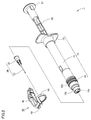
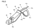
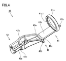
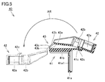
- FIG. 1 It is a perspective view of the syringe which concerns on embodiment of this invention. It is a disassembled perspective view of the syringe shown in FIG. It is a perspective view in the expansion
- FIG. 1 is a perspective view of a syringe according to an embodiment of the present invention
- FIG. 2 is an exploded perspective view of the syringe shown in FIG.
- FIGS. 3 and 4 are perspective views of the injection needle safety device shown in FIG. 1 in a developed state, and are schematic cross-sectional views showing the rotation operation of the injection needle safety device shown in FIG.
- the syringe 1 includes a barrel 10, a plunger 20, a syringe needle 30, and a syringe safety device 40.
- the barrel 10 includes a cylindrical body 11, an adapter 12 attached by being extrapolated to the front end of the cylindrical body 11, and a finger hooking member 13 attached by being extrapolated to the rear end of the cylindrical body 11.
- a nozzle portion 12 a and a luer lock portion 12 b are provided at the front end of the adapter 12, and a fitting groove 12 c is provided on the outer peripheral surface of a portion of the adapter 12 that is externally inserted into the cylindrical body 11.
- the cylindrical body 11 is a part mainly filled with a medicine and has a substantially cylindrical shape.
- the nozzle part 12a is a part for discharging the medicine filled in the barrel 10, and has a substantially cylindrical shape.
- the luer lock portion 12b is a portion for attaching the injection needle 30 to the barrel 10, and has a substantially cylindrical shape. Further, the luer lock portion 12b is positioned so as to surround the nozzle portion 12a.
- the fitting groove 12c is a portion for attaching the injection needle safety device 40 to the barrel 10, and is constituted by a groove having an annular shape.
- a discharge port for discharging a medicine is provided at the tip of the nozzle portion 12a, and the discharge port is connected to the needle tube 31 of the injection needle 30 in a state where the injection needle 30 is attached to the front end portion of the barrel 10. Is done.
- a female screw for screwing a needle base 32 provided at the rear end of the injection needle 30 is provided on the inner peripheral surface of the luer lock portion 12b, and the needle base 32 is screwed into the female screw.
- the injection needle 30 is attached to the front end of the barrel 10.
- the finger hooking member 13 is a part where fingers are hung to push the plunger 20 into the barrel 10 during injection.
- the plunger 20 has a rod-shaped rod, a flange portion 21 provided at the rear end of the rod, and a gasket (not shown) attached to the front end of the rod.
- the plunger 20 is for pushing the medicine into the barrel 10 to discharge the medicine from the discharge port described above.
- the gasket attached to the front end of the rod is a part that seals the inside of the barrel 10 in a liquid-tight manner, and pushes the drug toward the discharge port by sliding in the cylindrical body 11 when the rod is pushed. It is also a part of.
- the flange part 21 is a site
- the injection needle 30 has the needle tube 31 and the needle base 32 as described above.
- the needle tube 31 is made of a metal thin tube and has a sharp pointed tip.
- the needle tube 31 is used to administer the medicine discharged from the nozzle portion 12a of the barrel 10 under the skin of the patient by being pierced through the patient's skin.
- the needle base 32 is made of a resin member, and a protrusion that is screwed into the female screw of the luer lock portion 12b described above is provided at the rear end thereof.
- the needle base 32 is a part for fixing the injection needle 30 to the barrel 10, and the needle tube 31 is fixed to the needle base 32 using, for example, an adhesive.
- the safety device 40 for the injection needle is for preventing the tip of the needle tube 31 of the injection needle 30 from being accidentally pierced by a finger or the like after the syringe 1 is used, and in a state where it is assembled to the barrel 10. used.
- the injection needle safety device 40 includes a base portion 41, a cover portion 42, and a hinge portion 43, for example, injection molding made of a single member made of resin. Composed of products.
- a material of the safety device 40 for injection needles for example, polyethylene resin, polypropylene resin, polystyrene resin, polycarbonate resin, transparent ABS resin, AS resin and the like can be suitably used.
- the base portion 41 includes a fixed portion 41 a having an annular shape and an extension provided so as to extend from a predetermined position in the circumferential direction of the fixed portion 41 a toward the front end side. It includes a protruding portion 41b and a locking portion 41c provided to protrude from the predetermined position of the fixed portion 41a toward the rear end side.
- a fitting protrusion 41a1 configured to be fitted in the fitting groove 12c provided on the outer peripheral surface of the adapter 12 of the barrel 10 described above is provided.
- the fixed portion 41a is a part for assembling the injection needle safety device 40 with respect to the barrel 10, and the fitting protrusion 41a1 is fitted into the fitting groove 12c by being externally inserted into the adapter 12 of the barrel 10 at the time of assembling. Is fixed with respect to the barrel 10.
- the cover portion 42 includes a box-shaped accommodation portion 42a having one surface opened, a first locked portion 42c provided protruding from a predetermined position on the outer bottom surface side of the cover portion 42, and an inner portion of the cover portion 42. And a second locked portion 42b provided protruding from a predetermined position on the bottom side.
- the accommodating part 42a has a shape capable of covering the tip of the needle tube 31 by accommodating the tip of the needle tube 31 of the injection needle 30 therein.
- the first locked portion 42c has an L-shaped claw shape that can be locked by the locking portion 41c provided on the base portion 41 described above, and the second locked portion 42 b has a front-view V-shaped claw shape that can be locked by the needle tube 31 of the injection needle 30 (that is, a claw shape that can be hooked on the needle tube 31).
- the hinge portion 43 is a portion that rotatably connects the base portion 41 and the cover portion 42, and includes a first arm portion 43 a that is continuous with the front end of the extension portion 41 b of the base portion 41 described above, and the cover portion described above.
- 42 includes a second arm portion 43b that is continuous with the base end of the accommodating portion 42a, and a thin portion 43c that is continuous with the first arm portion 43a and the second arm portion 43b.
- the thin portion 43c is formed to be thinner than the first arm portion 43a and the second arm portion 43b, thereby constituting a rotation shaft of the hinge portion 43.
- the first arm portion 43a is erected from the front end of the extending portion 41b of the base portion 41 in a direction orthogonal to the extending direction of the extending portion 41b.
- the safety device 40 for the injection needle having the above-described configuration rotates the thin portion 43 c provided on the hinge portion 43 by connecting the base portion 41 and the cover portion 42 by the hinge portion 43.
- the moving shaft is configured to be capable of rotating along the direction of the arrow AR shown in the drawing.
- the cover portion 42 in a state where the first locked portion 42 c provided on the cover portion 42 is locked by the locking portion 41 c provided on the base portion 41 is indicated by a solid line.
- the cover portion 42 in a state where the locking of the first locked portion 42c by the locking portion 41c is released is indicated by a chain line.
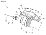
- FIG. 6 to 8 are views for explaining a method of using the syringe shown in FIG. 1, and FIG. 6 is a state where the cover portion is held by the base portion (a state where the cover portion is in the first position).
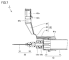
- FIG. 7 is a schematic cross-sectional view showing a state where the holding of the cover part with respect to the base part is released, and FIG. 8 is a state where the cover part is held by the injection needle (the cover part is in the second position).
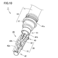
- FIG. 9 is an enlarged perspective view of the main part of the syringe in the state shown in FIG. 6, and FIG. 10 is an enlarged perspective view of the main part of the syringe in the state shown in FIG.
- the various methods of the use method of the syringe 1 in this Embodiment and the safety device 40 for injection needles in the said usage method are demonstrated.
- the injection needle safety device 40 is used in a state where it is assembled to the barrel 10, and in particular, it is assumed that it is preassembled to the barrel 10 prior to injection. is there.
- the thin portion 43 c provided on the hinge portion 43 of the injection needle safety device 40 is provided on the barrel 10. It is arranged extending in a direction orthogonal to the axis.
- the cover part 42 of the safety device 40 for injection needles can rotate centering on the rotational axis of the hinge part 43 which will be extended in the direction orthogonal to the axis line of the said barrel 10, and a barrel. It can move toward the front and back.
- the needle safety device 40 is in the state shown in FIGS. 6 and 9 (the cover 42 is in the first position).
- the first position means that the cover portion 42 is held by the base portion 41 when the first locked portion 42 c of the cover portion 42 is locked by the locking portion 41 c of the base portion 41.
- the cover part 42 is disposed on the rear end side of the barrel 10 with respect to the pivot shaft of the hinge part 43 along the axial direction of the barrel 10. Therefore, the tip of the needle tube 31 is not in the state covered with the accommodating portion 42a of the cover portion 42, but is in an exposed state.
- the injection needle safety device 40 has a non-deployed folded shape, and the cover portion 42 is disposed outside the extension portion 41b of the base portion 41.
- the cover part 42 is arranged outside the extension part 41b of the base part 41, there is a possibility that the view of a doctor or the like who handles the syringe 1 may be blocked during the injection.
- consideration is given so that the field of view is not blocked as much as possible, and there is no hindrance during injection. Therefore, a doctor or the like can surely see the tip of the needle tube 31 at the time of injection, and even when the injection needle safety device 40 is assembled to the barrel 10, the handleability at the time of injection is not impaired. Details of this point will be described later.
- the rear end of the cover part 42 is lifted in a direction away from the base part 41, whereby the first locked part 42c is locked by the locking part 41c. Accordingly, the holding of the cover portion 42 with respect to the base portion 41 is also released.
- both the locking portion 41c and the first locked portion 42c can be elastically deformed, the first locked portion 42c is easily locked with a small force by elastically deforming each other.
- the part 41c will be overcome and these locks can be released by a simple operation. In the state after the locking is released, the cover portion 42 can freely rotate about the rotation axis of the hinge portion 43 as a rotation center.
- the injection needle safety device 40 is in the state shown in FIGS. 8 and 10 (the cover part). 42 is in the second position).
- the second position is a position where the cover portion 42 is held by the injection needle 30 when the second locked portion 42b of the cover portion 42 is locked by the needle tube 31 of the injection needle 30. It corresponds to.
- the cover portion 42 is disposed in a state where the cover portion 42 is disposed closer to the tip end side of the needle tube 31 than the rotation shaft of the hinge portion 43 along the axial direction of the barrel 10. For this reason, the tip of the needle tube 31 is covered with the cover portion 42 by being housed inside the housing portion 42 a of the cover portion 42.
- the injection needle safety device 40 is deployed, and the base portion 41, the hinge portion 43, and the cover portion 42 are arranged substantially linearly along the axial direction of the barrel 10.
- the second locked portion 42b can be elastically deformed, the second locked portion 42b is easily pressed with a small force by pressing the second locked portion 42b toward the needle tube 31. Is elastically deformed and gets over the needle tube 31, and the second locked portion 42b can be locked by the needle tube 31 by a simple operation.
- the needle tube The lock of the second locked portion 42b by 31 is not released.
- the tip of the needle tube 31 is covered with the cover portion 42 as described above, and thus the needle tube 31 of the injection needle 30 after use of the syringe 1. It is possible to reliably prevent the tip of the finger from being accidentally stabbed into a finger or the like.
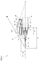
- FIG. 11 is a schematic view for explaining the reason why the safety device for the injection needle does not get in the way even during the injection in the syringe 1 shown in FIG. Next, with reference to FIG. 11, the reason why the injection needle safety device 40 does not get in the way at the time of injection in the syringe 1 according to the present embodiment will be described in detail.
- the cover portion 42 of the safety device 40 for the injection needle is in the first position, the cover portion 42 is disposed outside the extending portion 41b of the base portion 41 as described above. Yes.
- the configuration of the cover portion 42 provided in the injection needle safety device 40 particularly the base portion 41 of the cover portion 42.
- the configuration of the holding portion, the posture of the cover portion 42 in a state where the cover portion 42 is held by the base portion 41, the position of the rotation axis of the hinge portion 43 provided in the injection needle safety device 40, the shape of the cover portion 42 Thus, consideration is given so that the needle safety device 40 does not get in the way even during injection.
- the cover portion 42 of the safety device 40 for the injection needle is in the first position, the cover portion 42 is tilted toward the barrel 10 (more specifically, the side where the hinge portion 43 is located).
- the base end of the cover part 42 is relatively disposed radially outside the barrel 10 and the tip of the cover part 42 on the side where the hinge part 43 is not located (the end opposite to the base end) is By being disposed relatively radially inward of the barrel 10, the cover portion 42 is configured so as to be inclined so as to approach the barrel 10 from the proximal end side toward the distal end side.
- the cover portion 42 arranged at the first position rotates more than 180 ° with the rotation axis (the axis represented by the point P shown in the figure) of the hinge portion 43 as the rotation center, and thus the first described above.
- the cover portion 42 is configured to be inclined toward the barrel 10 in the state of being disposed at the first position so that the cover portion 42 is disposed at the position 2.
- the entire safety device 40 for the injection needle is disposed as far as possible on the rear end side of the syringe 1.
- the fixed portion 41 a of the base portion 41 is configured to be disposed at a position away from the tip of the needle tube 31 of the injection needle 30. That is, by ensuring a large distance LA shown in the figure, the field of view of a doctor or the like who handles the syringe 1 is not blocked as much as possible at the time of injection, and in this sense, the safety device 40 for the injection needle becomes an obstacle. There is nothing.
- the pivot shaft of the hinge portion 43 provided in the injection needle safety device 40 is arranged to some extent on the tip side of the needle tube 31 relative to the fixed portion 41a provided in the base portion 41 in the axial direction of the barrel 10. It is comprised so that. That is, the distance LB shown in the drawing is secured to be considerably large, so that the cover portion 42 is prevented from being lengthened. In this sense, the injection needle safety device 40 does not get in the way.
- the pivot shaft of the hinge part 43 provided in the injection needle safety device 40 is configured to be disposed outside the base part 41 in the radial direction of the barrel 10. That is, by ensuring the distance DB shown in the drawing to be somewhat larger than the distance DA, the cover portion 42 is tilted toward the barrel 10 in the state where the cover portion 42 of the safety device 40 for the injection needle is in the first position. The state is realized, and the field of view of a doctor or the like who handles the syringe 1 at the time of injection is not blocked as much as possible. In this sense, the safety device 40 for the injection needle does not get in the way.
- occur
- the visual field such as the above is not obstructed as much as possible, and in this sense, the injection needle safety device 40 does not get in the way.
- locking part 41c provided in the base part 41 of the safety device 40 for injection needles is provided in the rear end side of the barrel 10 rather than the to-be-fixed part 41a in the axial direction of the barrel 10.
- the safety device 40 for injection needles is a comparatively simple structure as mentioned above, it can implement
- the safety for the injection needle that has a simple configuration and does not disturb the injection. And a syringe provided with the device.
- FIG. 12 is a perspective view showing a packing state of the prefilled syringe when the configuration in the present embodiment described above is applied to the prefilled syringe.
- the prefilled syringe 1A is in a state in which a medicine is filled in the barrel 10 in advance, and the cap 50 is extrapolated to a luer lock portion 12b (see FIG. 2 and the like) provided on the adapter 12 of the barrel 10.
- the medicine is sealed from the outside.
- an elastic stopper that closes the tip of the needle tube 31 is provided inside the cap 50, and the tip of the needle tube 31 is closed by the elastic stopper, thereby preventing the drug from leaking out. .
- the prefilled syringe 1 ⁇ / b> A is installed in a state where the injection needle safety device 40 is assembled to the barrel 10 in addition to the cap 50 described above. In this state, the prefilled syringe 1A is provided to a doctor or the like.
- the present invention in which the barrel is divided into a cylindrical body, an adapter, and a finger hook member and these are combined to form the barrel is illustrated.
- the present invention can naturally be applied to a syringe having a barrel formed of a single member.
- a fitting protrusion is provided on the fixed portion of the safety device for the injection needle, and a fitting groove that can be fitted to the fitting protrusion is provided in the barrel, whereby injection is performed.
- the case where the needle safety device is configured to be fixed to the barrel has been described as an example, but the fitting protrusion is provided on the barrel and a fitting groove that can be fitted to the fitting protrusion is provided for the injection needle.
- the detailed configuration of the safety device for a needle shown in the embodiment of the present invention described above is merely an example, and the configuration can naturally be appropriately changed without departing from the gist of the present invention.
Landscapes
- Health & Medical Sciences (AREA)
- Engineering & Computer Science (AREA)
- Heart & Thoracic Surgery (AREA)
- Vascular Medicine (AREA)
- Anesthesiology (AREA)
- Biomedical Technology (AREA)
- Environmental & Geological Engineering (AREA)
- Hematology (AREA)
- Life Sciences & Earth Sciences (AREA)
- Animal Behavior & Ethology (AREA)
- General Health & Medical Sciences (AREA)
- Public Health (AREA)
- Veterinary Medicine (AREA)
- Infusion, Injection, And Reservoir Apparatuses (AREA)
Abstract
Description
Claims (10)
- バレルと、
前記バレルの前端部に取付けられた注射針と、
前記バレルの後端部側から前記バレルに内挿されることで前記バレルに取付けられたプランジャと、
前記バレルに組付けられた注射針用安全具とを備え、
前記注射針用安全具は、前記バレルに固定された被固定部を含むベース部と、前記注射針に含まれる針管の尖端を内部に収容することで前記針管の前記尖端を覆うことが可能な収容部を含むカバー部と、前記ベース部および前記カバー部を回動可能に連結するヒンジ部とを有し、
前記ヒンジ部の回動軸は、前記バレルの軸線と直交する方向に延在して設けられ、
前記ベース部には、係止部が設けられ、
前記カバー部には、前記係止部に係止される第1被係止部と、前記注射針に係止される第2被係止部とが設けられ、
前記カバー部は、前記バレルの軸線方向に沿って前記ヒンジ部の回動軸よりも前記バレルの前記後端部側に配置されることで前記針管の前記尖端を露出させるとともに、前記係止部によって前記第1被係止部が係止されることで前記ベース部に保持される第1の位置と、前記バレルの軸線方向に沿って前記ヒンジ部の回動軸よりも前記針管の前記尖端側に配置されることで前記針管の前記尖端を覆うとともに、前記注射針によって前記第2被係止部が係止されることで前記注射針に保持される第2の位置との間で回動可能となるように構成され、
前記カバー部は、前記第1の位置に配置された状態において、前記ヒンジ部が位置する側である基端側から前記ヒンジ部が位置しない側である先端側に向かうにつれて前記バレルに近づくように傾倒して位置し、前記ヒンジ部の回動軸を回転中心として180°を超えて回動することで前記第2の位置に配置される、シリンジ。 - 前記カバー部の前記ヒンジ部側に位置する部分の外形が、前記カバー部が前記第1の位置に配置された状態において、前記バレルの軸線方向に沿って前記針管の前記尖端側に向かうにつれて前記バレルに近づく傾斜形状を有している、請求項1に記載のシリンジ。
- 前記ヒンジ部の回動軸が、前記バレルの軸線方向において前記被固定部よりも前記針管の前記尖端側に設けられている、請求項1または2に記載のシリンジ。
- 前記ヒンジ部の回動軸が、前記バレルの径方向において前記ベース部よりも外側に設けられている、請求項1から3のいずれかに記載のシリンジ。
- 前記係止部が、前記バレルの軸線方向において前記被固定部よりも前記バレルの前記後端部側に設けられている、請求項1から4のいずれかに記載のシリンジ。
- 前記第2被係止部が、前記針管に引っ掛かり可能に構成された爪形状を有している、請求項1から5のいずれかに記載のシリンジ。
- 前記注射針用安全具が、樹脂製の単一の部材からなる射出成形品にて構成され、
前記ヒンジ部の回動軸が、周囲の部分に比して厚みが薄く形成された薄肉部にて構成されている、請求項1から6のいずれかに記載のシリンジ。 - 前記バレルは、前記プランジャが取付けられた筒状体と、前記筒状体の前端に外挿されることで取付けられるとともに前記注射針が取付けられたアダプタとを含み、
前記注射針用安全具が、前記筒状体に外挿された部分の前記アダプタに組付けられている、請求項1から7のいずれかに記載のシリンジ。 - 前記バレル内に外部から密封された状態で薬剤が充填されている、請求項1から8のいずれかに記載のシリンジ。
- シリンジのバレルに組付けられて使用される注射針用安全具であって、
シリンジのバレルに固定される被固定部を含むベース部と、
シリンジの前端部に取付けられた注射針に含まれる針管の尖端を内部に収容することで針管の尖端を覆うことが可能な収容部を含むカバー部と、
前記ベース部および前記カバー部を回動可能に連結するヒンジ部とを備え、
前記ヒンジ部の回動軸は、バレルの軸線と直交する方向に延在して設けられるように構成され、
前記ベース部には、係止部が設けられ、
前記カバー部には、前記係止部に係止される第1被係止部と、注射針に係止される第2被係止部とが設けられ、
前記カバー部は、バレルの軸線方向に沿って前記ヒンジ部の回動軸よりもバレルの後端部側に配置されることで針管の尖端を露出させるとともに、前記係止部によって前記第1被係止部が係止されることで前記ベース部に保持される第1の位置と、バレルの軸線方向に沿って前記ヒンジ部の回動軸よりも針管の尖端側に配置されることで針管の尖端を覆うとともに、注射針によって前記第2被係止部が係止されることで注射針に保持される第2の位置との間で回動可能となるように構成され、
前記カバー部は、前記第1の位置に配置された状態において、前記ヒンジ部が位置する側である基端側から前記ヒンジ部が位置しない側である先端側に向かうにつれてバレルに近づくように傾倒して位置し、前記ヒンジ部の回動軸を回転中心として180°を超えて回動することで前記第2の位置に配置されるように構成されている、注射針用安全具。
Priority Applications (5)
| Application Number | Priority Date | Filing Date | Title |
|---|---|---|---|
| JP2016511430A JPWO2015151596A1 (ja) | 2014-03-31 | 2015-02-12 | シリンジおよび注射針用安全具 |
| EP15772842.9A EP3127573B1 (en) | 2014-03-31 | 2015-02-12 | Syringe and injection needle safety instrument |
| US15/129,322 US10576218B2 (en) | 2014-03-31 | 2015-02-12 | Syringe and injection needle safety instrument |
| CN201580017897.1A CN106132464B (zh) | 2014-03-31 | 2015-02-12 | 注射器和注射针安全器具 |
| KR1020167030270A KR102285178B1 (ko) | 2014-03-31 | 2015-02-12 | 시린지, 및 주사 바늘용 안전 장치 |
Applications Claiming Priority (2)
| Application Number | Priority Date | Filing Date | Title |
|---|---|---|---|
| JP2014071818 | 2014-03-31 | ||
| JP2014-071818 | 2014-03-31 |
Publications (1)
| Publication Number | Publication Date |
|---|---|
| WO2015151596A1 true WO2015151596A1 (ja) | 2015-10-08 |
Family
ID=54239936
Family Applications (1)
| Application Number | Title | Priority Date | Filing Date |
|---|---|---|---|
| PCT/JP2015/053768 Ceased WO2015151596A1 (ja) | 2014-03-31 | 2015-02-12 | シリンジおよび注射針用安全具 |
Country Status (5)
| Country | Link |
|---|---|
| US (1) | US10576218B2 (ja) |
| EP (1) | EP3127573B1 (ja) |
| JP (1) | JPWO2015151596A1 (ja) |
| KR (1) | KR102285178B1 (ja) |
| WO (1) | WO2015151596A1 (ja) |
Cited By (2)
| Publication number | Priority date | Publication date | Assignee | Title |
|---|---|---|---|---|
| KR20210097704A (ko) * | 2018-11-27 | 2021-08-09 | 주식회사 대웅제약 | 주사기용 안전캡 및 이를 포함하는 안전주사기 |
| JP2022113602A (ja) * | 2021-01-25 | 2022-08-04 | プンリム ファーマテック インコーポレーテッド | 安全廃棄構造及び機能向上構造を有する注射器 |
Families Citing this family (1)
| Publication number | Priority date | Publication date | Assignee | Title |
|---|---|---|---|---|
| KR101940085B1 (ko) * | 2018-03-29 | 2019-01-18 | (주)풍림파마텍 | 주사바늘 재사용 방지캡 |
Citations (7)
| Publication number | Priority date | Publication date | Assignee | Title |
|---|---|---|---|---|
| JPH09103487A (ja) * | 1995-08-29 | 1997-04-22 | Becton Dickinson & Co | 針遮蔽組立体 |
| JPH1094606A (ja) * | 1996-08-23 | 1998-04-14 | Becton Dickinson & Co | 針組立体 |
| JPH1157005A (ja) * | 1997-06-23 | 1999-03-02 | Becton Dickinson & Co | シールドされた注射針アセンブリ |
| JP2003220139A (ja) * | 2002-01-31 | 2003-08-05 | Yoshino Kogyosho Co Ltd | 注射器 |
| JP2004538099A (ja) * | 2001-08-17 | 2004-12-24 | フューチュラ・メディカル・テクノロジーズ・インコーポレイテッド | 針アセンブリ用安全シールド |
| US20080208138A1 (en) * | 2007-02-26 | 2008-08-28 | Becton, Dickinson & Company | Syringe having a hinged needle shield |
| US20100198152A1 (en) * | 2007-08-01 | 2010-08-05 | Suddeutsche Feinmechanik Gmbh | Cannula device having pivotable needle guard |
Family Cites Families (9)
| Publication number | Priority date | Publication date | Assignee | Title |
|---|---|---|---|---|
| US4883469A (en) * | 1988-04-08 | 1989-11-28 | Glazier Stephen C | Guard assembly for hypodermic needle |
| US5151089A (en) * | 1990-05-16 | 1992-09-29 | Kirk Iii William D | Retractable protective needle sheath |
| WO2003011356A2 (en) * | 2001-07-27 | 2003-02-13 | Becton, Dickinson And Company | Luer connector assembly |
| US7001363B2 (en) | 2002-04-05 | 2006-02-21 | F. Mark Ferguson | Safety shield for medical needles |
| US7201736B2 (en) * | 2003-08-28 | 2007-04-10 | Smiths Medical Asd, Inc. | Needle protection assembly |
| US8251961B2 (en) * | 2003-09-22 | 2012-08-28 | Smiths Medical Asd, Inc. | Safety needle assembly and method for making the same |
| US8057431B2 (en) * | 2006-12-21 | 2011-11-15 | B. Braun Melsungen Ag | Hinged cap for needle device |
| WO2009007718A1 (en) | 2007-07-12 | 2009-01-15 | Star Syringe Limited | Needlestick prevention device |
| CA2931837A1 (en) * | 2013-12-05 | 2015-06-11 | Metier Medical Limited | A safety clip |
-
2015
- 2015-02-12 EP EP15772842.9A patent/EP3127573B1/en active Active
- 2015-02-12 JP JP2016511430A patent/JPWO2015151596A1/ja active Pending
- 2015-02-12 WO PCT/JP2015/053768 patent/WO2015151596A1/ja not_active Ceased
- 2015-02-12 US US15/129,322 patent/US10576218B2/en active Active
- 2015-02-12 KR KR1020167030270A patent/KR102285178B1/ko active Active
Patent Citations (7)
| Publication number | Priority date | Publication date | Assignee | Title |
|---|---|---|---|---|
| JPH09103487A (ja) * | 1995-08-29 | 1997-04-22 | Becton Dickinson & Co | 針遮蔽組立体 |
| JPH1094606A (ja) * | 1996-08-23 | 1998-04-14 | Becton Dickinson & Co | 針組立体 |
| JPH1157005A (ja) * | 1997-06-23 | 1999-03-02 | Becton Dickinson & Co | シールドされた注射針アセンブリ |
| JP2004538099A (ja) * | 2001-08-17 | 2004-12-24 | フューチュラ・メディカル・テクノロジーズ・インコーポレイテッド | 針アセンブリ用安全シールド |
| JP2003220139A (ja) * | 2002-01-31 | 2003-08-05 | Yoshino Kogyosho Co Ltd | 注射器 |
| US20080208138A1 (en) * | 2007-02-26 | 2008-08-28 | Becton, Dickinson & Company | Syringe having a hinged needle shield |
| US20100198152A1 (en) * | 2007-08-01 | 2010-08-05 | Suddeutsche Feinmechanik Gmbh | Cannula device having pivotable needle guard |
Cited By (6)
| Publication number | Priority date | Publication date | Assignee | Title |
|---|---|---|---|---|
| KR20210097704A (ko) * | 2018-11-27 | 2021-08-09 | 주식회사 대웅제약 | 주사기용 안전캡 및 이를 포함하는 안전주사기 |
| JP2022510157A (ja) * | 2018-11-27 | 2022-01-26 | デウン ファーマシューティカル カンパニー リミテッド | 注射器用安全キャップおよびこれを含む安全注射器 |
| JP7212778B2 (ja) | 2018-11-27 | 2023-01-25 | デウン ファーマシューティカル カンパニー リミテッド | 注射器用安全キャップおよびこれを含む安全注射器 |
| KR102557433B1 (ko) | 2018-11-27 | 2023-07-21 | 주식회사 대웅제약 | 주사기용 안전캡 및 이를 포함하는 안전주사기 |
| JP2022113602A (ja) * | 2021-01-25 | 2022-08-04 | プンリム ファーマテック インコーポレーテッド | 安全廃棄構造及び機能向上構造を有する注射器 |
| JP7510593B2 (ja) | 2021-01-25 | 2024-07-04 | プンリム ファーマテック インコーポレーテッド | 安全廃棄構造及び機能向上構造を有する注射器 |
Also Published As
| Publication number | Publication date |
|---|---|
| US20170119976A1 (en) | 2017-05-04 |
| EP3127573A4 (en) | 2017-10-18 |
| EP3127573A1 (en) | 2017-02-08 |
| JPWO2015151596A1 (ja) | 2017-04-13 |
| CN106132464A (zh) | 2016-11-16 |
| KR20160138272A (ko) | 2016-12-02 |
| KR102285178B1 (ko) | 2021-08-02 |
| US10576218B2 (en) | 2020-03-03 |
| EP3127573B1 (en) | 2021-04-07 |
Similar Documents
| Publication | Publication Date | Title |
|---|---|---|
| EP3481470B1 (en) | Cap assembly and a medicament delivery device comprising the cap assembly | |
| JP6765387B2 (ja) | 医療器具および医療器具の針での針刺し危害を阻止するための安全装置 | |
| US10426898B2 (en) | Retractable needle assemblies | |
| CN107206186B (zh) | 针头保护装置、胶接针头式注射器及该注射器的制造方法 | |
| US10485932B2 (en) | Needle assembly | |
| AU2008240105B2 (en) | Safety syringe | |
| JP2013517921A (ja) | 医療用針安全装置 | |
| US11672920B2 (en) | Intradermal needle, packaged article, and injection device | |
| JP7093775B2 (ja) | 安全針デバイス | |
| JP2013519415A (ja) | 医療用針カバー装置 | |
| JP6300940B2 (ja) | 薬剤投与装置 | |
| JP6211790B2 (ja) | 注射器 | |
| US10543322B2 (en) | Injection needle assembly for an injection device and an injection device comprising such assembly | |
| EP3681570B1 (en) | Safety assembly and medical device with safety assembly | |
| US9149584B2 (en) | Hinged shield assembly and related methods | |
| JPWO2015151596A1 (ja) | シリンジおよび注射針用安全具 | |
| EP3681569B1 (en) | Safety assembly | |
| US9492621B2 (en) | Needle safety device | |
| JP2022537671A (ja) | 医療用注射機器の針による針刺し損傷を防止するための安全機器 | |
| US12377221B2 (en) | Triggering mechanism for a medicament delivery device | |
| TWI921187B (zh) | 自動注射器 | |
| CN106132464B (zh) | 注射器和注射针安全器具 |
Legal Events
| Date | Code | Title | Description |
|---|---|---|---|
| 121 | Ep: the epo has been informed by wipo that ep was designated in this application |
Ref document number: 15772842 Country of ref document: EP Kind code of ref document: A1 |
|
| ENP | Entry into the national phase |
Ref document number: 2016511430 Country of ref document: JP Kind code of ref document: A |
|
| WWE | Wipo information: entry into national phase |
Ref document number: 15129322 Country of ref document: US |
|
| NENP | Non-entry into the national phase |
Ref country code: DE |
|
| REEP | Request for entry into the european phase |
Ref document number: 2015772842 Country of ref document: EP |
|
| WWE | Wipo information: entry into national phase |
Ref document number: 2015772842 Country of ref document: EP |
|
| ENP | Entry into the national phase |
Ref document number: 20167030270 Country of ref document: KR Kind code of ref document: A |