WO2015151621A1 - ジェットエンジン、飛しょう体及びジェットエンジンの動作方法 - Google Patents
ジェットエンジン、飛しょう体及びジェットエンジンの動作方法 Download PDFInfo
- Publication number
- WO2015151621A1 WO2015151621A1 PCT/JP2015/054476 JP2015054476W WO2015151621A1 WO 2015151621 A1 WO2015151621 A1 WO 2015151621A1 JP 2015054476 W JP2015054476 W JP 2015054476W WO 2015151621 A1 WO2015151621 A1 WO 2015151621A1
- Authority
- WO
- WIPO (PCT)
- Prior art keywords
- fuel
- jet engine
- sectional area
- air
- injector
- Prior art date
- Legal status (The legal status is an assumption and is not a legal conclusion. Google has not performed a legal analysis and makes no representation as to the accuracy of the status listed.)
- Ceased
Links
Images




Classifications
-
- F—MECHANICAL ENGINEERING; LIGHTING; HEATING; WEAPONS; BLASTING
- F02—COMBUSTION ENGINES; HOT-GAS OR COMBUSTION-PRODUCT ENGINE PLANTS
- F02C—GAS-TURBINE PLANTS; AIR INTAKES FOR JET-PROPULSION PLANTS; CONTROLLING FUEL SUPPLY IN AIR-BREATHING JET-PROPULSION PLANTS
- F02C9/00—Controlling gas-turbine plants; Controlling fuel supply in air- breathing jet-propulsion plants
- F02C9/26—Control of fuel supply
- F02C9/32—Control of fuel supply characterised by throttling of fuel
-
- B—PERFORMING OPERATIONS; TRANSPORTING
- B64—AIRCRAFT; AVIATION; COSMONAUTICS
- B64D—EQUIPMENT FOR FITTING IN OR TO AIRCRAFT; FLIGHT SUITS; PARACHUTES; ARRANGEMENT OR MOUNTING OF POWER PLANTS OR PROPULSION TRANSMISSIONS IN AIRCRAFT
- B64D33/00—Arrangement in aircraft of power plant parts or auxiliaries not otherwise provided for
- B64D33/02—Arrangement in aircraft of power plant parts or auxiliaries not otherwise provided for of combustion air intakes
-
- F—MECHANICAL ENGINEERING; LIGHTING; HEATING; WEAPONS; BLASTING
- F02—COMBUSTION ENGINES; HOT-GAS OR COMBUSTION-PRODUCT ENGINE PLANTS
- F02C—GAS-TURBINE PLANTS; AIR INTAKES FOR JET-PROPULSION PLANTS; CONTROLLING FUEL SUPPLY IN AIR-BREATHING JET-PROPULSION PLANTS
- F02C7/00—Features, components parts, details or accessories, not provided for in, or of interest apart form groups F02C1/00 - F02C6/00; Air intakes for jet-propulsion plants
- F02C7/04—Air intakes for gas-turbine plants or jet-propulsion plants
-
- F—MECHANICAL ENGINEERING; LIGHTING; HEATING; WEAPONS; BLASTING
- F02—COMBUSTION ENGINES; HOT-GAS OR COMBUSTION-PRODUCT ENGINE PLANTS
- F02C—GAS-TURBINE PLANTS; AIR INTAKES FOR JET-PROPULSION PLANTS; CONTROLLING FUEL SUPPLY IN AIR-BREATHING JET-PROPULSION PLANTS
- F02C7/00—Features, components parts, details or accessories, not provided for in, or of interest apart form groups F02C1/00 - F02C6/00; Air intakes for jet-propulsion plants
- F02C7/22—Fuel supply systems
- F02C7/222—Fuel flow conduits, e.g. manifolds
-
- F—MECHANICAL ENGINEERING; LIGHTING; HEATING; WEAPONS; BLASTING
- F02—COMBUSTION ENGINES; HOT-GAS OR COMBUSTION-PRODUCT ENGINE PLANTS
- F02C—GAS-TURBINE PLANTS; AIR INTAKES FOR JET-PROPULSION PLANTS; CONTROLLING FUEL SUPPLY IN AIR-BREATHING JET-PROPULSION PLANTS
- F02C7/00—Features, components parts, details or accessories, not provided for in, or of interest apart form groups F02C1/00 - F02C6/00; Air intakes for jet-propulsion plants
- F02C7/22—Fuel supply systems
- F02C7/232—Fuel valves; Draining valves or systems
-
- F—MECHANICAL ENGINEERING; LIGHTING; HEATING; WEAPONS; BLASTING
- F02—COMBUSTION ENGINES; HOT-GAS OR COMBUSTION-PRODUCT ENGINE PLANTS
- F02C—GAS-TURBINE PLANTS; AIR INTAKES FOR JET-PROPULSION PLANTS; CONTROLLING FUEL SUPPLY IN AIR-BREATHING JET-PROPULSION PLANTS
- F02C9/00—Controlling gas-turbine plants; Controlling fuel supply in air- breathing jet-propulsion plants
- F02C9/26—Control of fuel supply
- F02C9/44—Control of fuel supply responsive to the speed of aircraft, e.g. Mach number control, optimisation of fuel consumption
-
- F—MECHANICAL ENGINEERING; LIGHTING; HEATING; WEAPONS; BLASTING
- F02—COMBUSTION ENGINES; HOT-GAS OR COMBUSTION-PRODUCT ENGINE PLANTS
- F02K—JET-PROPULSION PLANTS
- F02K7/00—Plants in which the working fluid is used in a jet only, i.e. the plants not having a turbine or other engine driving a compressor or a ducted fan; Control thereof
-
- F—MECHANICAL ENGINEERING; LIGHTING; HEATING; WEAPONS; BLASTING
- F02—COMBUSTION ENGINES; HOT-GAS OR COMBUSTION-PRODUCT ENGINE PLANTS
- F02K—JET-PROPULSION PLANTS
- F02K7/00—Plants in which the working fluid is used in a jet only, i.e. the plants not having a turbine or other engine driving a compressor or a ducted fan; Control thereof
- F02K7/10—Plants in which the working fluid is used in a jet only, i.e. the plants not having a turbine or other engine driving a compressor or a ducted fan; Control thereof characterised by having ram-action compression, i.e. aero-thermo-dynamic-ducts or ram-jet engines
- F02K7/14—Plants in which the working fluid is used in a jet only, i.e. the plants not having a turbine or other engine driving a compressor or a ducted fan; Control thereof characterised by having ram-action compression, i.e. aero-thermo-dynamic-ducts or ram-jet engines with external combustion, e.g. scram-jet engines
-
- F—MECHANICAL ENGINEERING; LIGHTING; HEATING; WEAPONS; BLASTING
- F02—COMBUSTION ENGINES; HOT-GAS OR COMBUSTION-PRODUCT ENGINE PLANTS
- F02K—JET-PROPULSION PLANTS
- F02K7/00—Plants in which the working fluid is used in a jet only, i.e. the plants not having a turbine or other engine driving a compressor or a ducted fan; Control thereof
- F02K7/10—Plants in which the working fluid is used in a jet only, i.e. the plants not having a turbine or other engine driving a compressor or a ducted fan; Control thereof characterised by having ram-action compression, i.e. aero-thermo-dynamic-ducts or ram-jet engines
- F02K7/18—Composite ram-jet/rocket engines
-
- F—MECHANICAL ENGINEERING; LIGHTING; HEATING; WEAPONS; BLASTING
- F23—COMBUSTION APPARATUS; COMBUSTION PROCESSES
- F23N—REGULATING OR CONTROLLING COMBUSTION
- F23N1/00—Regulating fuel supply
- F23N1/002—Regulating fuel supply using electronic means
-
- F—MECHANICAL ENGINEERING; LIGHTING; HEATING; WEAPONS; BLASTING
- F23—COMBUSTION APPARATUS; COMBUSTION PROCESSES
- F23R—GENERATING COMBUSTION PRODUCTS OF HIGH PRESSURE OR HIGH VELOCITY, e.g. GAS-TURBINE COMBUSTION CHAMBERS
- F23R3/00—Continuous combustion chambers using liquid or gaseous fuel
- F23R3/28—Continuous combustion chambers using liquid or gaseous fuel characterised by the fuel supply
-
- F—MECHANICAL ENGINEERING; LIGHTING; HEATING; WEAPONS; BLASTING
- F05—INDEXING SCHEMES RELATING TO ENGINES OR PUMPS IN VARIOUS SUBCLASSES OF CLASSES F01-F04
- F05D—INDEXING SCHEME FOR ASPECTS RELATING TO NON-POSITIVE-DISPLACEMENT MACHINES OR ENGINES, GAS-TURBINES OR JET-PROPULSION PLANTS
- F05D2220/00—Application
- F05D2220/30—Application in turbines
- F05D2220/32—Application in turbines in gas turbines
- F05D2220/323—Application in turbines in gas turbines for aircraft propulsion, e.g. jet engines
-
- F—MECHANICAL ENGINEERING; LIGHTING; HEATING; WEAPONS; BLASTING
- F05—INDEXING SCHEMES RELATING TO ENGINES OR PUMPS IN VARIOUS SUBCLASSES OF CLASSES F01-F04
- F05D—INDEXING SCHEME FOR ASPECTS RELATING TO NON-POSITIVE-DISPLACEMENT MACHINES OR ENGINES, GAS-TURBINES OR JET-PROPULSION PLANTS
- F05D2220/00—Application
- F05D2220/80—Application in supersonic vehicles excluding hypersonic vehicles or ram, scram or rocket propulsion
-
- F—MECHANICAL ENGINEERING; LIGHTING; HEATING; WEAPONS; BLASTING
- F05—INDEXING SCHEMES RELATING TO ENGINES OR PUMPS IN VARIOUS SUBCLASSES OF CLASSES F01-F04
- F05D—INDEXING SCHEME FOR ASPECTS RELATING TO NON-POSITIVE-DISPLACEMENT MACHINES OR ENGINES, GAS-TURBINES OR JET-PROPULSION PLANTS
- F05D2240/00—Components
- F05D2240/35—Combustors or associated equipment
-
- F—MECHANICAL ENGINEERING; LIGHTING; HEATING; WEAPONS; BLASTING
- F05—INDEXING SCHEMES RELATING TO ENGINES OR PUMPS IN VARIOUS SUBCLASSES OF CLASSES F01-F04
- F05D—INDEXING SCHEME FOR ASPECTS RELATING TO NON-POSITIVE-DISPLACEMENT MACHINES OR ENGINES, GAS-TURBINES OR JET-PROPULSION PLANTS
- F05D2250/00—Geometry
- F05D2250/90—Variable geometry
-
- F—MECHANICAL ENGINEERING; LIGHTING; HEATING; WEAPONS; BLASTING
- F05—INDEXING SCHEMES RELATING TO ENGINES OR PUMPS IN VARIOUS SUBCLASSES OF CLASSES F01-F04
- F05D—INDEXING SCHEME FOR ASPECTS RELATING TO NON-POSITIVE-DISPLACEMENT MACHINES OR ENGINES, GAS-TURBINES OR JET-PROPULSION PLANTS
- F05D2270/00—Control
- F05D2270/30—Control parameters, e.g. input parameters
- F05D2270/306—Mass flow
-
- F—MECHANICAL ENGINEERING; LIGHTING; HEATING; WEAPONS; BLASTING
- F23—COMBUSTION APPARATUS; COMBUSTION PROCESSES
- F23N—REGULATING OR CONTROLLING COMBUSTION
- F23N2237/00—Controlling
- F23N2237/02—Controlling two or more burners
-
- F—MECHANICAL ENGINEERING; LIGHTING; HEATING; WEAPONS; BLASTING
- F23—COMBUSTION APPARATUS; COMBUSTION PROCESSES
- F23N—REGULATING OR CONTROLLING COMBUSTION
- F23N2237/00—Controlling
- F23N2237/10—High or low fire
-
- F—MECHANICAL ENGINEERING; LIGHTING; HEATING; WEAPONS; BLASTING
- F23—COMBUSTION APPARATUS; COMBUSTION PROCESSES
- F23N—REGULATING OR CONTROLLING COMBUSTION
- F23N2241/00—Applications
- F23N2241/20—Gas turbines
Definitions
- the present invention relates to a jet engine, a flying object and a method of operating a jet engine.
- a ramjet engine and a scramjet engine are known as jet engines of an aircraft that fly faster than the speed of sound. These are jet engines that operate by taking in air.
- the inside of the combustor is subsonic
- the inside of the combustor is supersonic, and in any case, the flame blows off, etc. It is important not to cause a misfire (no flame holding) due to
- a method which utilizes a low speed region existing in the boundary layer developed on the wall surface of the combustor or around the flame holder installed on the wall surface of the combustor. There is. In order to hold a flame by these methods, it is necessary to diffuse and supply the fuel to an appropriate area near the wall of the combustor (hereinafter, also referred to as a “stable flame area”).
- FIG. 1 is a schematic cross-sectional view schematically showing the configuration of a jet engine.
- the jet engine 102 includes an airframe 110 and a cowl 140 provided below the airframe 110 so as to form a space 150 through which gas can flow.
- the front lower portion of the airframe 110 and the front portion of the cowl 140 constitute an inlet 111 for introducing air into the space 150.
- the middle lower portion of the airframe 110 and the middle portion of the cowl 140 constitute a combustor 112 which mixes and burns fuel and air.
- the rear lower portion of the airframe 110 and the rear portion of the cowl 140 constitute a nozzle 113 for expanding and releasing the combustion gas.
- the combustor 112 includes a fuel injector 120.
- the combustion injector 120 is provided on a wall surface 121 of a portion corresponding to the combustor 112 in a lower portion of the fuselage 110. Furthermore, a flame holder may be provided on the wall surface 121 behind the fuel injector 120 (not shown).
- the fuel injector 120 ejects the fuel G toward the space 150.
- the jet engine 102 mixes and burns the air taken in from the inlet 111 and the fuel G injected from the fuel injector 120 in the combustor 112, expands the combustion gas in the nozzle 113, and makes the aft of the fuselage 110 Send out.
- a portion of the fuel G is diffused and supplied to the low speed region present in the boundary layer developed on the wall surface 121 of the combustor 112, and flame holding is performed.
- the flame holder is present, a part of the fuel G is diffused and supplied to the low speed area existing around the flame holder installed on the wall surface 121 of the combustor 112, and the flame is held.
- the supersonic combustor includes a low-profile strut, a plurality of small pieces, and an injection nozzle.
- Struts of wedge-shaped cross section are disposed in the flow path of the supersonic air flow with the acute angle portion directed upstream, and have a back end face substantially orthogonal to the flow.
- a plurality of small pieces are provided on the rear end surface of the strut, have substantially the same width as the rear end surface, and extend downstream.
- An injection nozzle is provided between the small pieces of struts and injects fuel downstream.
- An object of the present invention is to provide a jet engine, a flying object and a method of operating the jet engine that can operate stably even at lower speeds.
- another optional further object of the present invention is to provide a jet engine, a flying object and a method of operating the jet engine capable of suppressing the fuel from reaching the difficult flame holding area. .
- the jet engine includes an inlet for taking in air, a combustor that burns fuel using air, and a fuel control unit that controls the supply of fuel.
- the combustor includes a fuel supply unit for delivering fuel, an injector having an opening for injecting the fuel supplied from the fuel supply unit, a pipe for supplying fuel from the fuel supply unit to the opening, and a pipe And a channel cross-sectional area adjustment unit provided.
- the fuel control unit controls the fuel supply unit to deliver the total fuel flow rate to the injector according to the autopilot command.
- the fuel control unit controls the flow passage cross-sectional area adjustment unit to change the flow passage cross-sectional area of the pipe, thereby controlling the penetration height of the fuel.
- a method of operating a jet engine comprises operating an inlet for taking in air, a combustor for burning fuel using air, and a fuel control unit for controlling supply of fuel. It is.
- the combustor is a fuel supply unit for delivering fuel, an injector for injecting the fuel supplied from the fuel supply unit, the injector including an opening for injecting the fuel, and the fuel from the fuel supply unit to the opening And a flow path cross-sectional area adjustment unit provided in the pipe.
- the method of operation of the jet engine includes the steps of the fuel supply unit delivering fuel to the injector at a total fuel flow rate according to the autopilot command, and the flow passage cross-sectional area adjustment so that the fuel passes through the flameable region. Controlling the section to change the flow path cross-sectional area of the pipe.
- the present invention it is possible to provide a jet engine, a flying object and a method of operating the jet engine that can operate stably even at lower speeds. Also, optionally, the present invention can provide a jet engine, a flying object and a method of operating the jet engine capable of suppressing the fuel from reaching the difficult flame holding region.
- FIG. 1 is a schematic cross-sectional view schematically showing the configuration of a jet engine.
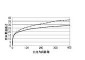
- FIG. 2 is a graph showing the relationship between the penetration height of fuel and the distance of air flow.
- FIG. 3A is a schematic view schematically showing the fuel injection of the combustor when the flight speed is high.
- FIG. 3B is a schematic view schematically showing the fuel injection of the combustor when the flight speed is high.
- FIG. 4A is a schematic view schematically showing the fuel injection of the combustor when the flight speed is low.
- FIG. 4B is a schematic view schematically showing the fuel injection of the combustor when the flight speed is low.
- FIG. 5 is a perspective view showing a configuration example of the flying object according to the embodiment.
- FIG. 6 is a schematic cross-sectional view schematically showing a configuration example of a jet engine according to the embodiment.
- FIG. 7A is a functional block diagram showing an example of the configuration of a jet engine according to the embodiment.
- FIG. 7B is a functional block diagram showing another example of the configuration of the fuel injector of the jet engine according to the embodiment.
- FIG. 8A is a schematic view schematically showing how fuel is injected when the flight speed is low in the combustor according to the embodiment.
- FIG. 8B is a schematic view schematically showing how fuel is injected when the flight speed is low in the combustor according to the embodiment.
- FIG. 9A is a schematic view schematically showing a state of fuel injection when the flight speed is high in the combustor according to the embodiment.
- FIG. 9B is a schematic view schematically showing how fuel is injected when the flight speed is high in the combustor according to the embodiment.
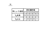
- FIG. 10 is a table showing an example of a table relating to the flight speed and the opening and closing of the valve by the fuel injection controller.
- FIG. 11A is a schematic view schematically showing a modified example of fuel injection when the flight speed is high in the combustor according to the embodiment.
- FIG. 11B is a schematic view schematically showing a modified example of fuel injection when the flight speed is high in the combustor according to the embodiment.
- FIG. 12 is a table showing another example of the table regarding the flight speed and the opening and closing of the valve by the fuel injection controller.
- FIG. 13A is a schematic cross-sectional view conceptually showing an example in which there is one fuel injection port in a jet engine according to a modification of the embodiment, and is perpendicular to the mainstream air passing through the jet engine.
- FIG. 5 is a cross sectional view, and is a cross sectional view when the valve is fully open.
- FIG. 13B is a schematic cross-sectional view conceptually showing an example in which there is one fuel injection port in a jet engine according to a modification of the embodiment, which is perpendicular to the mainstream air passing through the jet engine.
- FIG. 10 is a cross-sectional view, and is a cross-sectional view when the opening of the valve is narrowed.
- the “penetration height” of the fuel is defined to mean the distance by which the fuel diffuses in the vertical direction when the fuel is injected from the fuel injector in the direction perpendicular to the air flow direction.
- the fuel G when the fuel G is injected from the fuel injector 120 in the vertical direction (+ z direction), the fuel G diffuses in the vertical direction (+ z direction) and also diffuses in the air Air flow direction (+ x direction) Do.
- the distance by which the fuel G diffuses in the vertical direction (+ z direction) is the “penetration height” of the fuel G.
- mismentum flux of air is defined to mean the product of the mass of air passing through a unit area perpendicular to the flow direction of air per unit time and the velocity of the air.
- “momentum flux of fuel” is the momentum of the fuel immediately after being injected from the fuel injection port, and the mass of the fuel passing through the unit area perpendicular to the injection direction per unit time immediately after the injection; It is defined to mean the product of the fuel injection rate.
- FIG. 2 is a graph showing the relationship between the penetration height and the distance of the air G in the fuel G.
- the vertical axis indicates the penetration height (+ z direction; arbitrary unit) of the fuel G
- the horizontal axis indicates the distance (+ x direction; arbitrary unit) in which the fuel G is allowed to flow to the air Air.
- the reference (0) on the horizontal axis and the vertical axis is the position of the fuel injector 120.
- the broken line indicates the case where the flight velocity is low (the momentum flux of air Air is small), and the solid line indicates the case where the flight velocity is high (the momentum flux of air Air is large).
- the mass flow ratio of air Air to fuel G and the momentum flux of the injected fuel G in the vertical direction (+ z direction) are the same regardless of the velocity of the projectile.
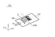
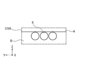
- FIGS. 3A and 3B are schematic views schematically showing the fuel injection of the combustor when the flight speed is high.
- FIG. 3A is a perspective view of the vicinity of the opening of the fuel injector 120
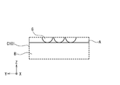
- FIG. 3B is a view showing the appearance of the fuel G at the cross section C101 of FIG. 3A.
- the cross section C101 is a yz cross section of the flow path of the air Air and the fuel G at a position away from the fuel injector 120 by a predetermined distance in the flow direction. Both figures are drawn upside down from FIG.
- the fuel G is supplied from the plurality of fuel injectors 120 provided on the wall surface 121 of the combustor 112 in the vertical direction (+ z direction). Thereafter, the fuel G is flowed in the flow direction (+ x direction) by the air Air taken in from the inlet 111.
- the fuel G passes through the area capable of holding flame (area capable of holding flame) B, and the area difficult to hold flame (holding flame difficult) Do not pass through area A). This is because the penetration speed of the fuel G is low because the flight speed is high and the momentum flux of the air Air is large (FIG. 2).
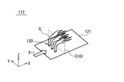
- FIG. 4A and FIG. 4B are schematic views schematically showing the fuel injection of the combustor when the flight speed is low.
- 4A is a perspective view of the vicinity of the opening of the fuel injector 120
- FIG. 4B is a view showing the state of the fuel G at the cross section C101 in FIG. 4A. It is drawn in reverse.
- fuel G is supplied from the plurality of fuel injectors 120 in the vertical direction (+ z direction). Thereafter, the fuel G is caused to flow in the flow direction (+ x direction) by the air Air.
- the fuel G passes through the flame holding difficult area A and can not pass the flame holding possible area B in the cross section C101 (yz cross section). This is because the flight speed is low and the momentum flux of the air Air is small, so the penetration height of the fuel G becomes high (see FIG. 2 if necessary). In this case, the flame can not be held, and the jet engine 102 may become inoperable. Therefore, it is difficult to use the jet engine 102 at a lower speed.
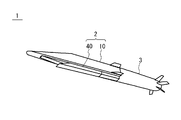
- FIG. 5 is a perspective view showing a configuration example of the flying object 1 according to the present embodiment.
- the flying body 1 includes a jet engine 2 and a rocket motor 3.
- the rocket motor 3 accelerates the flying object 1 from the speed at the start of the flight to a desired speed when the flying object 1 is caused to fly from the launcher.
- the speed at the start of the flight is zero when the projectile 1 is fired from the stationary launcher, and the vehicle is moving (or in flight) with the vehicle moving (or in flight)
- it is the moving speed (or flight speed) of the moving object (or flying object).
- the jet engine 2 After the flight vehicle 1 separates the rocket motor 3, the jet engine 2 further accelerates the flight vehicle 1 to fly toward the target.
- the jet engine 2 includes an airframe 10 and a cowl 40.
- the airframe 10 and the cowl 40 constitute an inlet, a combustor, and a nozzle of the jet engine 2 as described later.
- the jet engine 2 takes in air from the front at the inlet, mixes the air and fuel in the combustor and burns it, expands the combustion gas at the nozzle, and sends it backward. Thereby, the jet engine 2 obtains propulsion.
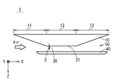
- FIG. 6 is a schematic cross-sectional view schematically showing a configuration example of a jet engine according to the present embodiment.
- the jet engine 2 includes an airframe 10 and a cowl 40 provided below the airframe 10 to form a space 50 through which gas can flow.
- the front lower portion of the airframe 10 and the front portion of the cowl 40 constitute an inlet 11 for introducing air into the space 50.
- the middle lower portion of the airframe 10 and the middle portion of the cowl 40 constitute a combustor 12 which mixes and burns fuel and air.
- the lower rear portion of the airframe 10 and the rear portion of the cowl 40 constitute a nozzle 13 for expanding and releasing the combustion gas.
- the combustor 12 is provided with a fuel injector 20.
- the fuel injectors 20 are provided on the wall 21 of the lower portion of the fuselage 10 in a portion corresponding to the combustor 12.
- the fuel injector 20 injects the fuel G stored in the airframe 10 toward the space 50 in a substantially vertical direction (+ z direction).
- the injected fuel G is mixed with the air taken in from the inlet 11 and burns. Further, at an early stage of combustion, the fuel G is burned by being ignited by an igniter (not shown) or the like.
- the fuel injector 20 has one or more openings in the lower portion of the fuselage 10.
- the fuel injector 20 is supplied with fuel at a flow rate according to the autopilot command.
- the fuel injector 20 may be configured such that the number of openings injecting fuel at low speed or the flow passage cross section in the pipe supplying fuel is the number of openings injecting fuel at high speed or It is controlled to be larger than the flow passage cross sectional area.
- the fuel injectors 20 are exemplified by a plurality of openings provided side by side in the span direction of the airframe 10.
- controlling the flow passage cross-sectional area includes controlling at least one of the plurality of pipes to control the number of openings for injecting the fuel.
- control of the flow path cross-sectional area in the pipe there is an option as to at which position of the pipe the flow path cross-sectional area is controlled. That is, for example, of the piping, the flow passage cross-sectional area at the opening of the fuel injector may be controlled, or the flow passage cross-sectional area at a position away from the opening of the fuel injector may be controlled.
- the combustor 12 may further include a flame holder on the wall surface 21 rearward of the fuel injector 20 (not shown).
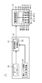
- FIG. 7A is a functional block diagram showing an example of the configuration of a jet engine according to the present embodiment.
- the jet engine 2 includes a combustor 12 and a fuel control unit 37.
- the combustor 12 burns fuel using the air taken in from the inlet 11.
- the fuel control unit 37 controls the supply of fuel in the combustor 12.
- the combustor 12 includes a fuel supply unit 22 and a fuel injector 20.
- the fuel supply unit 22 delivers the fuel to the fuel injector 20.
- the fuel injector 20 injects the supplied fuel into the air flow space 50.
- the fuel injector 20 includes a plurality of fuel injection ports (openings) 30-1 to 30-5, a plurality of pipes 43, 44-1 to 44-5, and a plurality of valves 42-1 to 42-5. It contains.
- the plurality of fuel injection ports (openings) 30-1 to 30-5 preferably have the same area.
- “the area is the same” includes that "the area is substantially the same”.
- “approximately the same area” means that the ratio of the largest to the smallest of the area of the fuel injection port is 1 ⁇ maximum one / minimum one ⁇ 1.5.
- the plurality of pipes 43, 44-1 to 44-5 supply the fuel delivered from the fuel supply unit 22 to the plurality of fuel injection ports 30-1 to 30-5.
- one end of the pipe 44-1 is connected to one end of the pipe 43, and the other end is connected to the fuel injection port 30-1.
- the pipe 44-2 has one end connected to one end of the pipe 43 and the other end connected to the fuel injection port 30-2.
- the pipe 44-3 has one end connected to one end of the pipe 43 and the other end connected to the fuel injection port 30-3.
- the pipe 44-4 has one end connected to one end of the pipe 43 and the other end connected to the fuel injection port 30-4.
- the pipe 44-5 has one end connected to one end of the pipe 43, and the other end connected to the fuel injection port 30-5.
- the other end of the pipe 43 is connected to the fuel supply unit 22.
- the plurality of fuel injection ports 30-1 to 30-5 are a plurality of openings provided in the wall surface 21.
- the plurality of fuel injection ports 30-1 to 30-5 inject the fuel supplied from the plurality of pipes 44-1 to 44-5.
- the plurality of fuel injection ports 30-1 to 30-5 are arranged side by side generally in the span direction (generally the y direction) which is a direction perpendicular to the direction of the air flow path.
- vertical includes generally vertical.
- perpendicularly vertical is meant to include the range of ⁇ 5 ° with respect to the vertical and the vertical (in other words, the range of 85 ° to 95 °).
- the direction of the air flow path means the longitudinal direction of the combustor (specifically, the x direction from the upstream side to the downstream side with respect to the flow of the mainstream air).
- the shape of the plurality of openings is not particularly limited, and may be a circle, an ellipse, a polygon, or a combination thereof.
- the number of fuel injection ports 30 is not particularly limited. The arrangement of the fuel injection ports 30 is not particularly limited as long as they are arranged generally in the y direction.
- the plurality of valves (flow passage cross-sectional area adjustment units) 42-1 to 42-5 are provided in the middle of the plurality of pipes 44-1 to 44-5.
- the valve 42-1 is provided in the middle of the pipe 44-1.
- the valve 42-2 is provided in the middle of the pipe 44-2.
- the valve 42-3 is provided in the middle of the pipe 44-3.
- the valve 42-4 is provided in the middle of the pipe 44-4.
- the valve 42-5 is provided in the middle of the pipe 44-5.
- the flow path cross-sectional area adjustment unit may be anything that can adjust the flow path cross-sectional area, may be a valve, or may be a mass flow controller capable of adjusting the flow rate of the fuel G. It may be a set of a valve and a mass flow controller.
- valves (and / or mass flow controllers) 42-1 to 42-5 By opening / closing five valves (and / or mass flow controllers) 42-1 to 42-5, desired fuel injection ports among the five fuel injection ports 30-1 to 30-5
- the fuel G can be supplied to 30.
- a plurality of valves (and / or mass flow controllers) make it possible to individually control the flow rate of fuel injection at the plurality of fuel injection ports 30.
- the fuel control unit 37 sends control signals to the fuel supply unit 22 of the combustor 12 and the plurality of valves (and / or mass flow controllers) 42-1 to 42-5 to control the fuel supply unit 22 and the plurality of valves. For example, when the flight speed reaches a predetermined speed, the fuel control unit 37 forces the fuel supply unit 22 to forcibly deliver to the fuel injector 20 the total flow of fuel according to the autopilot command. , Control the fuel supply unit 22.
- the fuel supply unit 22 includes a metering pump that forcibly delivers the fuel of the total flow rate to the fuel injector 20 according to the autopilot command.
- valves 42-1 to 42-5 are opened at low speed, and the valves 42-1 and 42-5 are closed at high speed. Control the valves 42-1 to 42-5 so as to be in the open state.
- control of the valves 42-1 to 42-5 is not limited to the above example.
- the control of the fuel supply unit 22 is preferably performed independently of the control of the valves 42-1 to 42-5. That is, the control of the valves 42-1 to 42-5 is preferably independent of the control of the total flow rate of fuel.
- the fuel control unit 37 includes an autopilot 33, a fuel injection controller 31, and a flight speed measurement / estimator 32.
- the autopilot 33, the fuel injection controller 31, and the flight speed measurement / estimator 32 are independent computers (note that each computer has, for example, a hardware processor, a memory, and a communication interface). It may be.
- the autopilot 33 and the flight speedometer / estimator 32 may be provided outside the fuel control unit 37.
- the autopilot 33, the fuel injection controller 31, and the flight velocity measurement / estimator 32 may be configured by one computer.
- the fuel control unit 37 is, for example, one computer provided with a hardware processor, a memory, and a communication interface.
- the hardware processor executes the program stored in the memory to execute the fuel control unit 37 as an autopilot (automatic steering command device), a flight velocity measuring device (or a flight velocity estimator, or Function as a fuel injection controller.
- the flight velocity measurement / estimator 32 measures or estimates the flight velocity of the jet engine 2.
- the flight velocity measurement / estimator 32 is, for example, a pitot tube in the case of a measuring instrument.
- the flight velocity measurement / estimator 32 is, for example, a GPS device or an inertial navigation device in the case of the estimator 32, and in the case of the GPS device, the time change of its own position, and in the case of the inertial navigation device, its own acceleration. Estimate the velocity by integration.
- the total fuel flow rate is determined, for example, as follows. Air inflow from the inlet 11 based on the flight altitude (data of the altitude sensor) and the flight velocity (data of the flight velocity measurement / estimator 32) for a specific flight object or a specific jet engine You can determine the quantity.
- the fuel control unit 37 is configured to calculate the air inflow amount from the flying height and the flying speed.
- the memory of the fuel control unit 37 stores a table that associates the flight altitude and the flight velocity with the air inflow amount, and the fuel control unit 37 refers to the table to determine the air inflow amount.
- the thrust to be required of the jet engine is obtained in accordance with the speed command from the autopilot 33, the acceleration command and the like.
- the fuel control unit 37 may calculate the thrust.
- the total fuel flow rate to be supplied to the combustor 12 can be obtained from the thrust, the flight speed, the flight altitude, the air inflow, and the like.
- the total fuel flow rate is calculated by the fuel control unit 37.
- the fuel injection controller 31 controls the fuel supply unit 22 of the combustor 12 and the plurality of valves 42-1 based on the control signal from the autopilot 33 and data such as the flight velocity measurement / estimator 32 and the altitude sensor. To 42-5 are controlled by the control signal.
- the fuel injection controller 31 is exemplified by a microcomputer. For example, the fuel injection controller 31 instructs the fuel supply unit 22 on the total fuel flow rate to be delivered, based on the control signal from the autopilot 33. In response to the instruction, the fuel supply unit 22 delivers the fuel. Further, the fuel injection controller 31 opens / closes the plurality of valves 42-1 to 42-5 on the basis of data from the total fuel flow rate and / or the flight speed measurement / estimator 32, altitude sensor, etc.
- Control the opening degree When controlling the opening / closing or opening of the plurality of valves 42-1 to 42-5, the table 35 regarding the opening / closing or opening of the valve stored in the storage unit of the fuel injection controller 31 may be referred to. Control of opening / closing or opening of the plurality of valves 42-1 to 42-5 and the table 35 will be described later.
- One end of the pipe 44a-1 is connected to one end of the pipe 43a-1, and the other end is connected to the fuel injection port 30-1.
- the pipe 44a-5 has one end connected to one end of the pipe 43a-1, and the other end connected to the fuel injection port 30-5.
- the pipe 44a-2 has one end connected to one end of the pipe 43a-2, and the other end connected to the fuel injection port 30-2.
- the pipe 44a-3 has one end connected to one end of the pipe 43a-2, and the other end connected to the fuel injection port 30-3.
- the pipe 44a-4 has one end connected to one end of the pipe 43a-2, and the other end connected to the fuel injection port 30-4.
- the other end of the pipe 43 a-1 is connected to one end of the pipe 43.
- the other end of the pipe 43 a-2 is connected to one end of the pipe 43.
- the other end of the pipe 43 is connected to the fuel supply unit 22.
- the valve 42a-1 is provided in the middle of the pipe 43a-1.
- the valve 42a-2 is provided in the middle of the pipe 43a-2.
- the fuel G is supplied to the five fuel injection ports 30-1 to 30-5 by opening the two valves 42a-1 and 42a-2. By closing one valve 42a-1, the fuel G is supplied to the central three fuel injection ports 30-2 to 30-4, and to both of the two fuel injection ports 30-1 and 30-5. Supply of fuel G can be stopped. That is, by switching the two valves 42a-1 and 42a-2, at least two states can be created. The number of valves 42a used can be reduced.
- FIGS. 8A to 8B are schematic views schematically showing the state of fuel injection when the flight speed is low in the combustor according to the present embodiment.
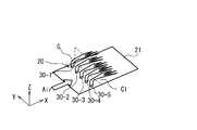
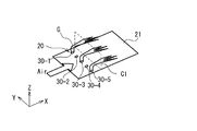
- FIG. 8A is a perspective view of the vicinity of the opening of the fuel injector 20.
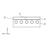
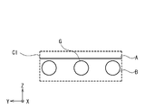
- FIG. 8B is a view showing the appearance of the fuel G at the cross section C1 of FIG. 8A.
- the cross section C1 is a yz cross section at a position away from the fuel injector 20 in the flow direction by a predetermined distance in the flow path of the air Air and the fuel G.
- the fuel G when the fuel G is delivered from the fuel supply unit 22 at the total fuel flow rate (total mass flow rate) according to the autopilot command, and the speed of the flying object 1 is low (mainly during acceleration),
- the fuel is injected from five fuel injection ports 30-1 to 30-5.
- the number of the fuel injection ports 30 for injecting the fuel G is relatively large, the injection speed and / or the density of the fuel G injected from one fuel injection port 30, and hence the momentum flux is relatively Decrease.
- the penetration height of the fuel G can be suppressed low.
- the cross section C1 yz In the cross section
- the fuel G passes through the flameable region B and is inhibited from passing through the flame difficult region A.
- the fuel supply unit 22 delivers the fuel G to the pipe 43 based on the control signal from the fuel control unit 37.
- the plurality of valves 42-2 to 42-4 are opened based on the control signal from the fuel control unit 37.
- the plurality of valves 42-1 and 42-5 are in the closed state based on the control signal from the fuel control unit 37.
- fuel G is supplied to the plurality of fuel injection ports (openings) 30-2 to 30-4 through the plurality of pipes 44-2 to 44-4.
- the plurality of fuel injection ports (openings) 30-2 to 30-4 inject the supplied fuel G into the space 50.
- the fuel G is not supplied to the plurality of fuel injection ports (openings) 30-1 and 30-5, the supplied fuel G is not injected into the space 50 as shown in FIG. 9A. At this time, the fuel G is injected from the three fuel injection ports 30.
- fuel is injected from a large number of fuel injection ports 30 at low speed, and a few fuel injection ports 30 are injected at high speed.
- the sum of the flow path cross-sectional areas in the plurality of flow path cross-sectional area adjustment units (the plurality of valves 42) is increased at low speed, and each flow path in the plurality of flow path cross-sectional area adjustment units (the plurality of valves 42) It can also be said that the sum of the cross-sectional areas is reduced.
- valves 42-1 to 42-5 are opened at the low speed, and the valves 42-1 and 42-5 are not completely closed at the high speed, but a plurality of By reducing the sum of the flow path cross-sectional area of the valve 42 (sum of the opening degree), the same state as that of the above embodiment can be obtained.
- the penetration height is suppressed so as not to increase at low speed, and even when the momentum flux of the air Air is small, the fuel G can be supplied to the flame holding possible region B and diffused.
- the fuel G can be supplied to the flame holding possible region B and diffused even if the momentum flux of the air Air is large, so that the penetration height is not lowered at high speed. This can prevent the jet engine 2 from becoming inoperable.
- the fuel control unit 37 determines the total fuel flow rate to be delivered to the fuel injector 20 based on the autopilot command. Then, the fuel control unit 37 controls the fuel supply unit 22 to deliver the total fuel flow rate. In addition, the fuel control unit 37 controls the total fuel flow rate and the momentum flux of the mainstream air passing through the combustor 12 (in the case where it is difficult to measure or calculate the momentum flux of air, Instead of a bundle, for example, it is possible to use a plurality of streams based on "jet engine airspeed" or "jet engine airspeed and jet engine airspeed".
- the fuel control unit 37 controls the flow passage cross-sectional areas of the plurality of flow passage cross-sectional area adjustment units (the plurality of valves 42) in order to realize the determined "sum of the flow passage cross-sectional areas".
- control may be performed so that the flow path cross-sectional areas become equal, for example, each flow path by narrowing the valves 42-1 and 42-5 more than the valves 42-2 to 42-4.
- the cross sectional area may be controlled to be different.
- the total fuel flow rate and the cross sectional area of each flow path are controlled, whereby the fuel injection speed, density, or momentum of the fuel G injected from each of the fuel injection ports 30-1 to 30-5.
- the flux or the penetration height of the fuel is controlled, and the fuel G passes through the flameable region B.
- each fuel injection port 30 is provided with a throttling shutter (not shown), and the momentum flux of the fuel injected from the fuel injection port 30 is continuously adjusted by continuously squeezing each shutter. It is also good.
- each shutter serves as a flow path cross-sectional area adjustment unit.
- the fuel injection controller 31 obtains the velocity of the flight vehicle 1 from the flight velocity measurement / estimator 32.
- the fuel injection controller 31 determines which of the five valves 42-1 to 42-5 to open based on the velocity of the projectile 1.
- the fuel injection controller 31 refers to a table 35 relating to the velocity and opening / closing of the valves based on the velocity of the flying object 1, and which one of the five valves 42-1 to 42-5 is selected. Decide whether to open.
- FIG. 10 is a table showing an example of the table 35 regarding the velocity of the flying object and the opening and closing of the valve by the fuel injection controller 31.
- ⁇ indicates that the valve 42 is in the open state
- x indicates that the valve 42 is in the closed state.
- “1” to “5” indicate “30-1” to [30-5].
- the valves 42-1 to 42-5 are opened.
- the valves 42-1 and 42-5 are closed, and the other valves 42-2, 42-3 and 42-4 are kept open.
- the table 35 is an example, and the opening / closing pattern and the number of steps of the valve 42 are not limited to this example.
- the predetermined velocity v 0 is determined based on the design of the flying object 1.
- the velocity of the flying object 1 is relatively slow, and it is assumed that the velocity is less than a predetermined velocity v0.
- the valves 42-1 to 42-5 of the five fuel injectors 20 are opened, and the fuel supply unit 22 sets the fuel G to five fuel injection ports 30-1 to 30-5. Supply to.
- the number of the fuel injection ports 30 injecting the fuel G is relatively large, the flow rate of the fuel G injected from one fuel injection port 30 is small, and the momentum flux of the fuel relatively decreases.
- the penetration height of the fuel G is suppressed to a low level, and the fuel G is suppressed from reaching the flame holding difficult area A, and is supplied to the flame holding possible area B.
- the jet engine 2 can hold the flame and can continue to operate (FIGS. 8A to 8B).
- FIG. 11A and FIG. 11B are schematic views schematically showing a modified example of fuel injection when the flight speed is fast in the combustor according to the present embodiment.
- FIG. 11A is a perspective view of the vicinity of the opening of the fuel injector 20.
- FIG. 11B is a view showing a state of the fuel G at the cross section C1 of FIG. 11A.
- flight soaring speed is slow, it is the same as FIG. 8A and 8B.
- the plurality of valves 42-1, 42-3 and 42-5 are opened based on the control signal from the fuel control unit 37. ing.
- the plurality of valves 42-2 and 42-4 are closed based on the control signal from the fuel control unit 37.
- the plurality of fuel injection ports (openings) 30-1, 30-3, and 30-5 are supplied with the fuel G through the plurality of pipes 44-1, 44-3, and 44-5.
- the plurality of fuel injection ports (openings) 30-1, 30-3, and 30-5 inject the supplied fuel G into the space 50.
- the supplied fuel G is not injected into the space 50 as shown in FIG. 11A. At this time, the fuel G is injected from the three fuel injection ports 30.
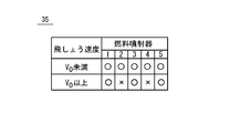
- FIG. 12 is a table showing another example of the table 35 regarding the velocity of the flying object and the opening and closing of the valve by the fuel injection controller 31.
- the valves 42-2 and 42-4 are closed, and the other valves 42-1, 42-3 and 42-5 are closed. Is different in that it remains open.
- the injection of the fuel G as shown in FIG. 11A and FIG. 11B is realized by the table 35 of FIG.
- the number of fuel injection ports 30 for injecting the fuel G at the initial low speed (mainly during acceleration) when acceleration is started by the jet engine 2 is It is relatively high.
- the fuel flow rate per fuel injection port 30 can be reduced, and the momentum flux of the fuel G can be kept low. Therefore, even at low speeds, the fuel G can be supplied and diffused to the flame holding possible region B while suppressing the penetration height from becoming high. This can prevent the jet engine 2 from becoming inoperable.
- the number of fuel injection ports 30 for injecting the fuel G is relatively reduced.
- the fuel flow rate per fuel injection port 30 can be increased, and the momentum flux of the fuel G can be increased. Therefore, the penetration height can be maintained even at high speed, and the fuel G can be supplied to the flameable region B and diffused. Thereby, the jet engine 2 can be operated continuously.
- the present embodiment at low speeds, the plurality of valves 42 are opened, and the number of fuel injection ports 30 for injecting fuel increases, and at high speeds, the number of the plurality of valves 42 that were open The valve is closed, and the number of fuel injection ports 30 for injecting fuel is reduced.
- the present embodiment is not limited to this example, and the number of fuel injection ports 30 injecting fuel at low speed is greater than the number of fuel injection ports 30 injecting fuel at high speed. It may be in any form. In other words, as long as the number of valves 42 through which fuel can flow at low speed is greater than the number of valves 42 through which fuel can flow at high speed, any form may be used.
- valves 42 when there are ten valves 42 (42-1 to 42-10 in order from the end), at low speed, the valves 42-1, 42-2, 42-5, 42-6, 42-9, for example. , 42-10 are open, the other valves 42 are closed, and at high speed, the valves 42-3, 42-4, 42-7, 42-8 are opened and the other valves 42 are closed. It may be in the form.
- the present embodiment has been described by way of example in which a jet engine is applied to a flying object, the present embodiment is not limited to this example, and a multistage launcher equipped with a rocket and a jet engine or It is also applicable to aircraft.
Landscapes
- Engineering & Computer Science (AREA)
- Chemical & Material Sciences (AREA)
- Combustion & Propulsion (AREA)
- Mechanical Engineering (AREA)
- General Engineering & Computer Science (AREA)
- Aviation & Aerospace Engineering (AREA)
- Nozzles (AREA)
- Electrical Control Of Air Or Fuel Supplied To Internal-Combustion Engine (AREA)
- Fuel-Injection Apparatus (AREA)
Abstract
ジェットエンジンは、空気を取り込むインレットと、空気を用いて燃料を燃焼する燃焼器(12)と、燃料の供給を制御する燃料制御部(37)とを具備する。燃焼器(12)は、燃料を供給する燃料供給部(22)と、燃料を噴射する噴射器(20)とを備える。噴射器(20)は、燃料を噴射する開口部(30-1~30-5)を含む。燃料供給部(22)は、オートパイロットの指令に応じた流量で噴射器(20)へ燃料を供給する。燃料制御部(37)は、低速時に燃料を噴射する開口部(30)の数又は燃料を供給する配管中の流路断面積が、高速時に燃料を噴射する開口部(30)の数又は燃料を供給する配管中の流路断面積よりも大きくなるように、噴射器(20)を制御する。
Description
本発明は、ジェットエンジン、飛しょう体及びジェットエンジンの動作方法に関する。
音速より速く飛しょうする機体のジェットエンジンとして、ラムジェットエンジン、スクラムジェットエンジンが知られている。これらは空気を取り入れて作動するジェットエンジンであり、ラムジェットエンジンでは燃焼器内部は亜音速であり、スクラムジェットエンジンでは燃焼器内部は超音速であり、いずれの場合にも、火炎の吹き消え等による失火(保炎不可)を発生させないことが重要である。
ジェットエンジンの燃焼用の炎を維持する保炎メカニズムとして、燃焼器の壁面に発達した境界層や燃焼器の壁面に設置した保炎器周辺などに存在する低速領域を活用する方法が知られている。これらの方式で保炎するためには、燃焼器の壁面近傍の適切な領域(以下、「保炎可能領域」ともいう)へ向け燃料を拡散させて、供給する必要がある。
図1は、ジェットエンジンの構成を模式的に示す概略断面図である。ジェットエンジン102は、機体110と、機体110の下方に気体の流通可能な空間150を形成するように設けられたカウル140とを備えている。機体110の前方の下方部分とカウル140の前方部分とは、空間150へ空気を導入するインレット111を構成している。機体110の中間の下方部分とカウル140の中間部分とは、燃料と空気とを混合し燃焼させる燃焼器112を構成している。機体110の後方の下方部分とカウル140の後方部分とは、燃焼気体を膨張させて放出するノズル113を構成している。燃焼器112は、燃料噴射器120を備えている。燃焼噴射器120は、機体110の下方部分における、燃焼器112に対応する部分の壁面121に設けられている。更に、燃料噴射器120よりも後方の壁面121に保炎器を備えていてもよい(図示されず)。燃料噴射器120は、空間150へ向けて燃料Gを噴出する。ジェットエンジン102は、インレット111から取り入れた空気と、燃料噴射器120から噴射した燃料Gとを燃焼器112で混合して燃焼させ、その燃焼ガスをノズル113で膨張させて、機体110の後方へ送出する。燃焼器112での保炎については、燃焼器112の壁面121に発達した境界層に存在する低速領域へ、燃料Gの一部が拡散して供給され、保炎される。保炎器が存在する場合、燃焼器112の壁面121に設置された保炎器周辺に存在する低速領域へ、その燃料Gの一部が拡散して供給され、保炎される。
関連する技術として特開平8-219408号公報に超音速燃焼器が開示されている。この超音速燃焼器は、楔断面形状のストラットと、複数の小片と、噴射ノズルとを備えている。楔断面形状のストラットは、超音速空気流の流路内に鋭角部を上流側に向けて配置され、かつ流れにほぼ直交する後端面を有する。複数の小片は、ストラットの後端面に設けられ、該後端面にほぼ等しい幅を有し、かつ下流側に延びている。噴射ノズルは、ストラットの前記小片の間に設けられ、下流に向けて燃料を噴射する。
本発明の目的は、より低速でも安定的に動作することが可能なジェットエンジン、飛しょう体及びジェットエンジンの動作方法を提供することにある。また、本発明の任意付加的な他の目的は、燃料が保炎困難な領域に到達することを抑制することが可能なジェットエンジン、飛しょう体及びジェットエンジンの動作方法を提供することにある。
いくつかの実施形態に係るジェットエンジンは、空気を取り込むインレットと、空気を用いて燃料を燃焼する燃焼器と、燃料の供給を制御する燃料制御部とを具備している。燃焼器は、燃料を送出する燃料供給部と、燃料供給部から供給された燃料を噴射する開口部が形成された噴射器と、燃料供給部から開口部に燃料を供給する配管と、配管に設けられた流路断面積調整部とを備えている。燃料制御部は、燃料供給部を、オートパイロットの指令に応じた総燃料流量を噴射器に送出するように制御する。燃料制御部は、流路断面積調整部を制御して、配管の流路断面積を変化させることにより、燃料の貫通高さを制御する。
いくつかの実施形態に係るジェットエンジンの動作方法は、空気を取り込むインレットと、空気を用いて燃料を燃焼する燃焼器と、燃料の供給を制御する燃料制御部とを具備するジェットエンジンの動作方法である。燃焼器は、燃料を送出する燃料供給部と、燃料供給部から供給された燃料を噴射する噴射器であって、燃料を噴射する開口部を含む噴射器と、燃料供給部から開口部に燃料を供給する配管と、配管に設けられた流路断面積調整部とを備えている。ジェットエンジンの動作方法は、燃料供給部が、オートパイロットの指令に応じた総燃料流量で噴射器へ燃料を送出するステップと、燃料が保炎可能領域を通過するように、流路断面積調整部を制御して、配管の流路断面積を変化させるステップとを具備している。
本発明により、より低速でも安定的に動作することが可能なジェットエンジン、飛しょう体及びジェットエンジンの動作方法を提供することができる。また、任意付加的に、本発明により、燃料が保炎困難な領域に到達することを抑制することが可能なジェットエンジン、飛しょう体及びジェットエンジンの動作方法を提供することができる。
添付の図面は、実施形態の説明を助けるために本明細書に組み込まれる。なお、図面は、本発明を、図示された例および説明された例に限定するものとして解釈されるべきではない。
図1は、ジェットエンジンの構成を模式的に示す概略断面図である。
図2は、燃料における貫通高さと空気に流される距離との関係を示すグラフである。
図3Aは、飛しょう速度が速い場合での燃焼器の燃料噴射の様子を模式的に示す概略図である。
図3Bは、飛しょう速度が速い場合での燃焼器の燃料噴射の様子を模式的に示す概略図である。
図4Aは、飛しょう速度が遅い場合での燃焼器の燃料噴射の様子を模式的に示す概略図である。
図4Bは、飛しょう速度が遅い場合での燃焼器の燃料噴射の様子を模式的に示す概略図である。
図5は、実施の形態に係る飛しょう体の構成例を示す斜視図である。
図6は、実施の形態に係るジェットエンジンの構成例を模式的に示す概略断面図である。
図7Aは、実施の形態に係るジェットエンジンの構成の一例を示す機能ブロック図である。
図7Bは、実施の形態に係るジェットエンジンの燃料噴射器の構成の他の例を示す機能ブロック図である。
図8Aは、実施の形態に係る燃焼器において飛しょう速度が遅い場合での燃料噴射の様子を模式的に示す概略図である。
図8Bは、実施の形態に係る燃焼器において飛しょう速度が遅い場合での燃料噴射の様子を模式的に示す概略図である。
図9Aは、実施の形態に係る燃焼器において飛しょう速度が速い場合での燃料噴射の様子を模式的に示す概略図である。
図9Bは、実施の形態に係る燃焼器において飛しょう速度が速い場合での燃料噴射の様子を模式的に示す概略図である。
図10は、飛しょう速度と燃料噴射制御器による弁の開閉に関するテーブルの一例を示す表である。
図11Aは、実施の形態に係る燃焼器において飛しょう速度が速い場合での燃料噴射の変形例の様子を模式的に示す概略図である。
図11Bは、実施の形態に係る燃焼器において飛しょう速度が速い場合での燃料噴射の変形例の様子を模式的に示す概略図である。
図12は、飛しょう速度と燃料噴射制御器による弁の開閉に関するテーブルの他の例を示す表である。
図13Aは、実施の形態の変形例に係るジェットエンジンにおいて、燃料噴射口が1つである場合の例を概念的に示す概略断面図であり、ジェットエンジンを通過する主流空気に対して垂直な断面図であり、かつ、弁が全開であるときの断面図である。
図13Bは、実施の形態の変形例に係るジェットエンジンにおいて、燃料噴射口が1つである場合の例を概念的に示す概略断面図であり、ジェットエンジンを通過する主流空気に対して垂直な断面図であり、かつ、弁の開度を絞ったときの断面図である。
以下、実施の形態に係るジェットエンジン及びジェットエンジンの動作方法に関して、添付図面を参照して説明する。ここでは、ジェットエンジンを飛しょう体に適用した例について説明する。以下の詳細な説明においては、実施形態の包括的な理解を提供するために、説明の目的で多くの詳細な特定事項が開示される。しかし、一又は複数の実施形態は、これらの詳細な特定事項なしで実行可能であることが明らかである。
(発明者によって認識された事項)
まず、本明細書における重要な用語を定義する。燃料の「貫通高さ」とは、空気の流れ方向に対して垂直方向に、燃料噴射器から燃料を噴射する時に、当該燃料が当該垂直方向に拡散する距離を意味するものと定義する。例えば、図1において、燃料Gは、燃料噴射器120から垂直方向(+z方向)に噴射されると、垂直方向(+z方向)に拡散しながら、空気Airの流れ方向(+x方向)にも拡散する。ここで、燃料Gが垂直方向(+z方向)に拡散する距離が、燃料Gの「貫通高さ」である。また、「空気の運動量流束」とは、単位時間当たりに空気の流れ方向に垂直な単位面積を通過する空気の質量と、当該空気の速度との積を意味するものと定義する。また、「燃料の運動量流束」とは、燃料噴射口から噴射された直後の燃料の運動量であって、噴射直後に単位時間当たりに噴射方向に垂直な単位面積を通過する燃料の質量と、当該燃料の噴射速度との積を意味するものと定義する。
まず、本明細書における重要な用語を定義する。燃料の「貫通高さ」とは、空気の流れ方向に対して垂直方向に、燃料噴射器から燃料を噴射する時に、当該燃料が当該垂直方向に拡散する距離を意味するものと定義する。例えば、図1において、燃料Gは、燃料噴射器120から垂直方向(+z方向)に噴射されると、垂直方向(+z方向)に拡散しながら、空気Airの流れ方向(+x方向)にも拡散する。ここで、燃料Gが垂直方向(+z方向)に拡散する距離が、燃料Gの「貫通高さ」である。また、「空気の運動量流束」とは、単位時間当たりに空気の流れ方向に垂直な単位面積を通過する空気の質量と、当該空気の速度との積を意味するものと定義する。また、「燃料の運動量流束」とは、燃料噴射口から噴射された直後の燃料の運動量であって、噴射直後に単位時間当たりに噴射方向に垂直な単位面積を通過する燃料の質量と、当該燃料の噴射速度との積を意味するものと定義する。
図2は、燃料Gにおける、貫通高さと空気Airに流される距離との関係を示すグラフである。縦軸は燃料Gの貫通高さ(+z方向;任意単位)を示し、横軸は燃料Gが空気Airに流される距離(+x方向;任意単位)を示している。横軸及び縦軸の基準(0)は、燃料噴射器120の位置である。破線は飛しょう体速度が遅い(空気Airの運動量流束が小さい)場合を示し、実線は飛しょう体速度が速い(空気Airの運動量流束が大きい)場合を示している。ただし、空気Airと燃料Gの質量流量比及び噴射される燃料Gの垂直方向(+z方向)の運動量流束は飛しょう体の速度によらず同一としている。
図2に示されるように、飛しょう速度が速い場合(実線:主に、巡航段階にあたる)、貫通高さは低くなる傾向にある。これは、空気Airの流れ方向の運動量流束が高く、その流れの方向に燃料Gが流され易いためと考えられる。一方、飛しょう速度が遅い場合(破線:主に、加速段階にあたる)、貫通高さは高くなる傾向にある。これは、空気Airの運動量流束が低く、その流れの方向に燃料Gが流され難いためと考えられる。
図3A及び図3Bは、飛しょう速度が速い場合での燃焼器の燃料噴射の様子を模式的に示す概略図である。ただし、図3Aは燃料噴射器120の開口部付近の斜視図であり、図3Bは図3Aの断面C101における燃料Gの様子を示す図である。また、断面C101は、空気Air及び燃料Gの流路における、燃料噴射器120から流れ方向に所定距離だけ離れた位置での流路のyz断面である。いずれの図も図1とは上下を逆にして描かれている。
図3Aに示されるように、燃料Gは、燃焼器112の壁面121に設けられた複数の燃料噴射器120から垂直方向(+z方向)に供給される。その後、燃料Gは、インレット111から取り入れられた空気Airにより、その流れ方向(+x方向)へ流される。そのとき、図3Bに示されるように、断面C101(yz断面)では、燃料Gが、保炎可能な領域(保炎可能領域)Bを通過しており、保炎困難な領域(保炎困難領域)Aを通過することはない。これは、飛しょう速度が速く、空気Airの運動量流束が大きいため、燃料Gの貫通高さが低いためである(図2)。
図4A及び図4Bは、飛しょう速度が遅い場合での燃焼器の燃料噴射の様子を模式的に示す概略図である。たたし、図4Aは燃料噴射器120の開口部付近の斜視図であり、図4Bは図4Aにおける断面C101における燃料Gの様子を示す図であり、いずれの図も図1とは上下を逆にして描かれている。
図3Aの場合と同様に、図4Aに示されるように、燃料Gは、複数の燃料噴射器120から垂直方向(+z方向)に供給される。その後、燃料Gは、空気Airにより、その流れ方向(+x方向)へ流される。そのとき、図3Bの場合と異なり、図4Bに示されるように、断面C101(yz断面)では、燃料Gが、保炎困難領域Aを通過しており、保炎可能領域Bを通過できない。これは、飛しょう速度が遅く、空気Airの運動量流束が小さいため、燃料Gの貫通高さが高くなってしまうためである(必要であれば、図2を参照。)。この場合、保炎することができず、ジェットエンジン102が作動不可となる可能性がある。そのため、より低速でジェットエンジン102を用いることが困難となる。
本実施の形態に係る飛しょう体1の構成について説明する。
図5は、本実施の形態に係る飛しょう体1の構成例を示す斜視図である。飛しょう体1は、ジェットエンジン2と、ロケットモータ3とを具備している。ロケットモータ3は、飛しょう体1を発射装置から飛しょうさせるとき、飛しょう体1を飛しょう開始時の速度から所望の速度まで加速する。ただし、飛しょう開始時の速度は、飛しょう体1が静止している発射装置から発射されるときは、速度ゼロであり、飛しょう体が移動中(または、飛行中)の移動体(または、飛行体)の発射装置から発射されるときは、その移動体(または、飛行体)の移動速度(または、飛行速度)である。ジェットエンジン2は、飛しょう体1がロケットモータ3を分離した後、飛しょう体1を更に加速して、目標へ向かって飛しょうさせる。ジェットエンジン2は、機体10とカウル40とを備えている。機体10とカウル40とは、後述されるように、ジェットエンジン2のインレット、燃焼器及びノズルを構成している。ジェットエンジン2は、インレットにて前方から空気を取り入れ、燃焼器にてその空気と燃料とを混合し、燃焼させ、ノズルにてその燃焼ガスを膨張させ、後方へ送出する。それにより、ジェットエンジン2は推進力を得る。
図5は、本実施の形態に係る飛しょう体1の構成例を示す斜視図である。飛しょう体1は、ジェットエンジン2と、ロケットモータ3とを具備している。ロケットモータ3は、飛しょう体1を発射装置から飛しょうさせるとき、飛しょう体1を飛しょう開始時の速度から所望の速度まで加速する。ただし、飛しょう開始時の速度は、飛しょう体1が静止している発射装置から発射されるときは、速度ゼロであり、飛しょう体が移動中(または、飛行中)の移動体(または、飛行体)の発射装置から発射されるときは、その移動体(または、飛行体)の移動速度(または、飛行速度)である。ジェットエンジン2は、飛しょう体1がロケットモータ3を分離した後、飛しょう体1を更に加速して、目標へ向かって飛しょうさせる。ジェットエンジン2は、機体10とカウル40とを備えている。機体10とカウル40とは、後述されるように、ジェットエンジン2のインレット、燃焼器及びノズルを構成している。ジェットエンジン2は、インレットにて前方から空気を取り入れ、燃焼器にてその空気と燃料とを混合し、燃焼させ、ノズルにてその燃焼ガスを膨張させ、後方へ送出する。それにより、ジェットエンジン2は推進力を得る。
次に、本実施の形態に係るジェットエンジンについて説明する。
図6は、本実施の形態に係るジェットエンジンの構成例を模式的に示す概略断面図である。ジェットエンジン2は、機体10と、機体10の下方に気体の流通可能な空間50を形成するように設けられたカウル40とを備えている。機体10の前方の下方部分とカウル40の前方部分とは、空間50へ空気を導入するインレット11を構成している。機体10の中間の下方部分とカウル40の中間部分とは、燃料と空気とを混合し燃焼させる燃焼器12を構成している。機体10の後方の下方部分とカウル40の後方部分とは、燃焼気体を膨張させて放出するノズル13を構成している。燃焼器12は、燃料噴射器20を備えている。
図6は、本実施の形態に係るジェットエンジンの構成例を模式的に示す概略断面図である。ジェットエンジン2は、機体10と、機体10の下方に気体の流通可能な空間50を形成するように設けられたカウル40とを備えている。機体10の前方の下方部分とカウル40の前方部分とは、空間50へ空気を導入するインレット11を構成している。機体10の中間の下方部分とカウル40の中間部分とは、燃料と空気とを混合し燃焼させる燃焼器12を構成している。機体10の後方の下方部分とカウル40の後方部分とは、燃焼気体を膨張させて放出するノズル13を構成している。燃焼器12は、燃料噴射器20を備えている。
燃料噴射器20は、機体10の下方部分における、燃焼器12に対応する部分の壁面21に設けられている。燃料噴射器20は、機体10に格納された燃料Gを概ね垂直方向(+z方向)に空間50へ向けて噴射する。噴射された燃料Gは、インレット11から取り入れた空気と混合されて燃焼する。また、燃焼の初期には、燃料Gはイグナイタ(図示されず)等により点火されることにより燃焼する。燃料噴射器20は、機体10の下方部分に設けられた1つ又は複数の開口部を有している。燃料噴射器20は、オートパイロットの指令に応じた流量で燃料を供給される。そして、燃料噴射器20は、低速時に燃料を噴射する開口部の数又は燃料を供給する配管中の流路断面積が、高速時に燃料を噴射する開口部の数又は燃料を供給する配管中の流路断面積よりも大きくなるように、制御される。ただし、その開口部の形状や数や配置は任意性がある。燃料噴射器20は、機体10のスパン方向に並んで設けられた複数の開口部に例示される。なお、流路断面積を制御することには、複数の配管のうちの少なくとも1つを閉状態にして、燃料を噴射する開口部の数を制御することが包含される。また、配管中の流路断面積を制御することについて、配管のどの位置における流路断面積を制御するかについては任意性がある。すなわち、例えば、配管のうち、燃料噴射器の開口部における流路断面積を制御してもよいし、燃料噴射器の開口部から離れた位置における流路断面積を制御してもよい。
なお、燃焼器12は、更に、燃料噴射器20よりも後方の壁面21に保炎器を備えていてもよい(図示されず)。
図7Aは、本実施の形態に係るジェットエンジンの構成の一例を示す機能ブロック図である。ジェットエンジン2は、燃焼器12と、燃料制御部37とを備えている。燃焼器12は、インレット11から取り入れた空気を用いて燃料を燃焼する。燃料制御部37は、燃焼器12での燃料の供給を制御する。燃焼器12は、燃料供給部22と、燃料噴射器20とを備えている。燃料供給部22は、燃料を燃料噴射器20へ送出する。燃料噴射器20は、供給された燃料を空気の流れる空間50へ噴射する。
燃料噴射器20は、複数の燃料噴射口(開口部)30-1~30-5と、複数の配管43、44-1~44-5と、複数の弁42-1~42-5とを含んでいる。なお、複数の燃料噴射口(開口部)30-1~30-5は、面積が同じであることが好ましい。なお、本明細書において、「面積が同じ」には、「面積が概ね同じ」であることが包含される。ここで、「面積が概ね同じ」とは、燃料噴射口の面積の最大のものと最小のものとの比が1≦最大のもの/最小のもの≦1.5であることを意味する。
複数の配管43、44-1~44-5は、燃料供給部22から送出される燃料を、複数の燃料噴射口30-1~30-5へ供給する。具体的には、配管44-1は一端を配管43の一端に、他端を燃料噴射口30-1にそれぞれ接続されている。配管44-2は一端を配管43の一端に、他端を燃料噴射口30-2にそれぞれ接続されている。配管44-3は一端を配管43の一端に、他端を燃料噴射口30-3にそれぞれ接続されている。配管44-4は一端を配管43の一端に、他端を燃料噴射口30-4にそれぞれ接続されている。配管44-5は一端を配管43の一端に、他端を燃料噴射口30-5にそれぞれ接続されている。配管43は他端を燃料供給部22に接続されている。
複数の燃料噴射口30-1~30-5は、壁面21に設けられた複数の開口部である。複数の燃料噴射口30-1~30-5は、複数の配管44-1~44-5から供給された燃料を噴射する。複数の燃料噴射口30-1~30-5は、空気の流路の方向に対して垂直方向である概ねスパン方向(概ねy方向)に並んで配置されている。なお、本明細書において、垂直には、概ね垂直であることが包含される。また、概ね垂直とは、垂直及び垂直に対して±5°の範囲(換言すれば、85°以上95°以下の範囲)を含む意味である。また、空気流路の方向とは、燃焼器の長手方向(具体的には、主流空気の流れに関し、上流側から下流側に向かうx方向)を意味する。また、複数の開口部の形状には特に制限はなく、円形、楕円形、多角形、又はそれらの組み合わせであってもよい。また、燃料噴射口30の数について特に制限はない。燃料噴射口30の配置についても、概ねy方向に並んで配置されていれば特に制限はない。
複数の弁(流路断面積調整部)42-1~42-5は、複数の配管44-1~44-5の途中に設けられている。具体的には、弁42-1は、配管44-1の途中に設けられている。弁42-2は、配管44-2の途中に設けられている。弁42-3は、配管44-3の途中に設けられている。弁42-4は、配管44-4の途中に設けられている。弁42-5は、配管44-5の途中に設けられている。なお、流路断面積調整部は、流路断面積を調整可能なものであれば何でもよく、弁であってもよいし、燃料Gの流量を調整可能なマスフローコントローラであってもよいし、弁とマスフローコントローラの組であってもよい。
この場合、5つの弁(及び/又はマスフローコントローラ)42-1~42-5を開/閉状態にすることで、5つの燃料噴射口30-1~30-5のうちの所望の燃料噴射口30へ燃料Gを供給することができる。言い換えると、このような複数の弁(及び/又はマスフローコントローラ)により、複数の燃料噴射口30での燃料噴射の流量を個別に制御することが可能となる。それにより、燃料Gを噴射する燃料噴射口の数または各燃料噴射口からの燃料噴射流量が異なる複数の状態を作り出すことができる。
燃料制御部37は、燃焼器12の燃料供給部22及び複数の弁(及び/又はマスフローコントローラ)42-1~42-5に制御信号を送り、燃料供給部22及び複数の弁を制御する。例えば、燃料制御部37は、飛しょう速度が所定の速度に達した段階で、燃料供給部22がオートパイロットの指令に応じた総流量の燃料を燃料噴射器20へ強制的に送出するように、燃料供給部22を制御する。例えば、燃料供給部22は、オートパイロットの指令に応じた総流量の燃料を燃料噴射器20へ強制的に送出する定量ポンプを備える。加えて、例えば、燃料制御部37は、低速時に弁42-1~42-5が開状態となり、高速時に弁42-1と弁42-5が閉状態となり、弁42-2~42-4が開状態となるように、弁42-1~42-5を制御する。ただし、弁42-1~42-5の制御は、上記の例に限られない。なお、前記燃料供給部22の制御は、弁42-1~42-5の制御とは独立して行われることが好ましい。すなわち、弁42-1~42-5の制御は、燃料の総流量の制御とは無関係であることが好ましい。
燃料制御部37は、オートパイロット33と、燃料噴射制御器31と、飛しょう速度計測/推定器32とを備えている。オートパイロット33と、燃料噴射制御器31と、飛しょう速度計測/推定器32とは、それぞれ、独立したコンピュータ(なお、各コンピュータは、例えば、ハードウェアプロセッサ、メモリ、通信インターフェースを備える。)であってもよい。なお、オートパイロット33と、飛しょう速度計/推定器32とは、燃料制御部37の外部に設けられていてもよい。
代替的に、オートパイロット33と、燃料噴射制御器31と、飛しょう速度計測/推定器32とは、1つのコンピュータによって構成されてもよい。1つのコンピュータによって構成される場合、燃料制御部37は、例えば、ハードウェアプロセッサ、メモリ、通信インターフェースを備える1つのコンピュータである。この場合、ハードウェアプロセッサは、メモリに記憶されたプログラムを実行することにより、燃料制御部37を、オートパイロット(自動操縦指令装置)、飛しょう速度計測器(または、飛しょう速度推定器、あるいは、飛しょう速度計測推定器)、燃料噴射制御器として機能させる。
飛しょう速度計測/推定器32は、ジェットエンジン2の飛しょう速度を計測又は推定する。飛しょう速度計測/推定器32は、計測器の場合、例えば、ピトー管である。飛しょう速度計測/推定器32は、推定器32の場合、例えば、GPS装置や慣性航法装置であり、GPS装置の場合は自身の位置の時間変化により、慣性航法装置の場合は自身の加速度の積分により速度を推定する。
燃料制御部37は、オートパイロット33から指示された総燃料流量、及び、飛しょう速度計測/推定器32のデータ、高度センサ(図示せず)のデータ、他のセンサ(図示されず)のデータ等に基づいて、燃料噴射制御器31を制御する。
なお、総燃料流量については、例えば、次のように決定される。ある特定の飛しょう体又はある特定のジェットエンジンについて、飛しょう高度(高度センサのデータ)及び飛しょう速度(飛しょう速度計測/推定器32のデータ)に基づいて、インレット11から流入する空気流入量を求めることができる。例えば、燃料制御部37は、飛しょう高度及び飛しょう速度から、前記空気流入量を計算により求めるように構成される。あるいは、燃料制御部37のメモリは、飛しょう高度及び飛しょう速度と、前記空気流入量とを対応付けるテーブルを記憶しており、燃料制御部37は、当該テーブルを参照して、前記空気流入量を求めるように構成してもよい。他方、オートパイロット33からの速度指令、加速度指令等に応じてジェットエンジンに要求すべき推力は、求められる。当該推力は、燃料制御部37が計算により求めることとしてもよい。そして、当該推力と、前記飛しょう速度と、前記飛しょう高度と、前記空気流入量等から、燃焼器12に供給すべき総燃料流量を求めることができる。例えば、当該総燃料流量は、燃料制御部37によって、計算により求められる。
燃料噴射制御器31は、オートパイロット33からの制御信号、並びに、飛しょう速度計測/推定器32及び高度センサ等のデータに基づいて、燃焼器12の燃料供給部22及び複数の弁42-1~42-5を制御信号により制御する。燃料噴射制御器31は、マイクロコンピュータに例示される。例えば、燃料噴射制御器31は、オートパイロット33からの制御信号に基づいて、送出すべき総燃料流量を燃料供給部22に対して指示する。当該指示に応じて、燃料供給部22は、燃料を送出する。また、燃料噴射制御器31は、前記総燃料流量、及び/又は、飛しょう速度計測/推定器32、高度センサ等からのデータに基づいて、複数の弁42-1~42-5の開閉又は開度を制御する。複数の弁42-1~42-5の開閉又は開度の制御に際しては、燃料噴射制御器31の記憶部に格納された弁の開閉又は開度に関するテーブル35を参照してもよい。複数の弁42-1~42-5の開閉又は開度の制御、及び、テーブル35については後述される。
なお、燃料噴射器20における、配管及び弁は、上記構成に限定されるものではない。図7Bは、本実施の形態に係るジェットエンジンの燃料噴射器の構成の他の例を示す機能ブロック図である。燃料噴射器20aは、複数の燃料噴射口30-1~30-5と、複数の配管43、43a-1、43a-2、44a-1~44a-5と、複数の弁42a-1~42a-2とを含んでいる。
配管44a-1は一端を配管43a-1の一端に、他端を燃料噴射口30-1にそれぞれ接続されている。配管44a-5は一端を配管43a-1の一端に、他端を燃料噴射口30-5にそれぞれ接続されている。配管44a-2は一端を配管43a-2の一端に、他端を燃料噴射口30-2にそれぞれ接続されている。配管44a-3は一端を配管43a-2の一端に、他端を燃料噴射口30-3にそれぞれ接続されている。配管44a-4は一端を配管43a-2の一端に、他端を燃料噴射口30-4にそれぞれ接続されている。配管43a-1は他端を配管43の一端に接続されている。配管43a-2は他端を配管43の一端に接続されている。配管43の他端は燃料供給部22に接続されている。弁42a-1は、配管43a-1の途中に設けられている。弁42a-2は、配管43a-2の途中に設けられている。
この場合、弁の数が少なくなっているが、2つの弁42a-1、42a-2を開状態にすることで、5つの燃料噴射口30-1~30-5に燃料Gを供給し、1つの弁42a-1を閉状態にすることで、中央の3つの燃料噴射口30-2~30-4に燃料Gを供給し、両側の2つの燃料噴射口30-1、30-5への燃料Gの供給を停止できる。すなわち、2つの弁42a-1、42a-2の切り替えにより、少なくとも2つの状態を作り出すことができる。使用する弁42aの数を少なくすることができる。
図8A~図8Bは、本実施の形態に係る燃焼器において飛しょう速度が遅い場合での燃料噴射の様子を模式的に示す概略図である。ただし、図8Aは燃料噴射器20の開口部付近の斜視図である。図8Bは図8Aの断面C1における燃料Gの様子を示す図である。また、断面C1は、空気Air及び燃料Gの流路における、燃料噴射器20から流れ方向に所定距離だけ離れた位置でのyz断面である。
燃料噴射器20において、燃料供給部22は、燃料制御部37からの制御信号に基づいて、配管43へ燃料Gを送出する。複数の弁(流路断面積調整部)42-1~42-5は、燃料制御部37からの制御信号に基づいて、開状態になっている。複数の燃料噴射口(開口部)30-1~30-5は、複数の配管44-1~44-5を介して燃料Gを供給される。そして、図8Aに示すように、複数の燃料噴射口(開口部)30-1~30-5は、供給された燃料Gを空間50へ噴射する。このとき、燃料Gは、5つの燃料噴射口30から噴射されている。
本実施の形態では、燃料Gがオートパイロットの指令に応じた総燃料流量(総質量流量)で燃料供給部22から送出され、飛しょう体1の速度が低速の場合(主に加速時)、5つの燃料噴射口30-1~30-5から噴射されている。この場合、燃料Gを噴射する燃料噴射口30の数が相対的に多いので、1つの燃料噴射口30から噴射される燃料Gの噴射速度及び/又は密度、ひいては、運動量流束は相対的に減少する。それにより、燃料Gの貫通高さを低く抑えることができる。その結果、飛しょう体1の速度が低速で、空気Airの運動量流束が小さい場合でも、図4A及び図4Bの事態が発生せずその結果、図8Bに示されるように、断面C1(yz断面)では、燃料Gが、保炎可能領域Bを通過しており、保炎困難領域Aを通過することが抑制される。
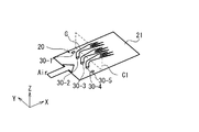
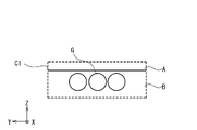
一方、図9A~図9Bは、本実施の形態に係る燃焼器において飛しょう速度が速い場合での燃料噴射の様子を模式的に示す概略図である。ただし、図9Aは燃料噴射器20の開口部付近の斜視図である。図9Bは図9Aの断面C1における燃料Gの様子を示す図である。
燃料噴射器20において、燃料供給部22は、燃料制御部37からの制御信号に基づいて、配管43へ燃料Gを送出する。複数の弁42-2~42-4は、燃料制御部37からの制御信号に基づいて、開状態になっている。一方、複数の弁42-1、42-5は、燃料制御部37からの制御信号に基づいて、閉状態になっている。その結果、複数の燃料噴射口(開口部)30-2~30-4は、複数の配管44-2~44-4を介して燃料Gを供給される。そして、図9Aに示すように、複数の燃料噴射口(開口部)30-2~30-4は、供給された燃料Gを空間50へ噴射する。一方、複数の燃料噴射口(開口部)30-1、30-5は、燃料Gを供給されないので、図9Aに示すように、供給された燃料Gを空間50へ噴射することはない。このとき、燃料Gは、3つの燃料噴射口30から噴射されている。
本実施の形態では、燃料Gがオートパイロットの指令に応じた総燃料流量(総質量流量)で燃料供給部22から送出され、飛しょう体1の速度が高速の場合(主に巡航時)、3つの燃料噴射口30-2~30-4から燃料Gが噴射されている。この場合、燃料Gを噴射する燃料噴射口30の数が相対的に少ないので、1つの燃料噴射口30から噴射される燃料Gの噴射速度及び/又は密度、ひいては、運動量流束は相対的に増加する。それにより、空気Airの運動量流束が大きい場合であっても、燃料Gの貫通高さを維持することができる。その結果、飛しょう体1の速度が高速で、空気Airの運動量流束が大きい場合、図9Bに示されるように、断面C1(yz断面)では、燃料Gが、保炎可能領域Bを通過することができる。
本実施の形態に関し、低速時に多数の燃料噴射口30で燃料を噴射し、高速時に少数の燃料噴射口30を噴射している。このことは、低速時には使用される複数の燃料噴射口30の断面積の和を大きくし、高速時には使用される複数の燃料噴射口30の断面積の和を小さくしている、と言い換えることもできる。あるいは、低速時には複数の流路断面積調整部(複数の弁42)における各流路断面積の和を大きくし、高速時には複数の流路断面積調整部(複数の弁42)における各流路断面積の和を小さくしている、と言い換えることもできる。この考えを応用すると、低速時に弁42-1~42-5を開状態とし、高速時に弁42-1、42-5を完全に閉状態にするのではなく、少しだけ開状態として、複数の弁42の流路断面積の和(開度の和)を小さくすることによっても、上記実施の形態と同様の状態を作ることができる。それにより、低速時に貫通高さが高くならないように抑えて、空気Airの運動量流束が小さい場合でも、燃料Gを保炎可能領域Bに供給し、拡散させることができる。加えて、高速時に貫通高さが低くならないようにして、空気Airの運動量流束が大きい場合でも、燃料Gを保炎可能領域Bに供給し、拡散させることができる。それにより、ジェットエンジン2が動作しなくなる事態を防止することができる。
次に、流路断面積の和を制御する場合の例について説明する。燃料制御部37は、オートパイロットの指令に基づいて、燃料噴射器20に送出すべき総燃料流量を求める。そして、燃料制御部37は、当該総燃料流量を送出するよう、燃料供給部22を制御する。加えて、燃料制御部37は、総燃料流量と、燃焼器12を通過する主流空気の運動量流束(空気の運動量流束を計測又は算出することが困難である場合には、空気の運動量流束の代わりに、例えば、「ジェットエンジンの対気速度」、又は、「ジェットエンジンの対気速度及びジェットエンジンの対気高度」を用いることが可能である。)とに基づいて、複数の流路断面積調整部(複数の弁42)における「各流路断面積の和」を決定する。ここで、「各流路断面積の和」は、燃料Gが、保炎可能領域Bを通過するように決定される。なお、各流路断面積は、例えば、流路断面積調整部において、流路断面積が最小となる部分の断面積とする。なお、流路断面積調整部が設けられていない配管44-1~44-5が存在する場合には、流路断面積調整部の設けられていない配管の流路断面積は、当該配管の断面積とする。そして、燃料制御部37は、決定された「各流路断面積の和」を実現すべく、複数の流路断面積調整部(複数の弁42)における各流路断面積を制御する。なお、各流路断面積が等しくなるように制御してもよいし、例えば、弁42-1、42-5を、弁42-2~42-4よりも大きく絞る等して、各流路断面積が異なるように制御してもよい。
上記により、総燃料流量と、各流路断面積とが制御されることにより、各燃料噴射口30-1~30-5から噴射される燃料Gの燃料噴射速度、密度、又は、燃料の運動量流束、あるいは、燃料の貫通高さは制御され、燃料Gが、保炎可能領域Bを通過することとなる。
代替的に、各燃料噴射口30に絞りシャッタ(図示せず)を設け、各シャッタを連続的に絞ることで、燃料噴射口30から噴射される燃料の運動量流束を連続的に調整してもよい。この場合、各シャッタが流路断面積調整部となる。
次に、実施の形態に係る飛しょう体1及びジェットエンジン2の動作方法の一例について説明する。
飛しょう体1は、設置位置から目標に向けて発射される。ロケットモータ3は、飛しょう体1を発射装置から飛しょうせるとき、飛しょう体1を飛しょう開始時の速度から所望の速度まで加速する。ただし、飛しょう開始時の速度は、飛しょう体1が静止している発射装置から発射されるときは、速度ゼロであり、飛しょう体が移動中(または、飛行中)の移動体(または、飛行体)の発射装置から発射されるときは、その移動体(または、飛行体)の移動速度(または、飛行速度)である。その後、飛しょう体1は、オートパイロット33の制御により、ロケットモータ3を切り離し、ジェットエンジン2により、加速し、飛しょうする。
ジェットエンジン2で加速を開始した当初の段階(加速時)では、飛しょう体1の速度は相対的に遅い。燃料噴射制御器31は、飛しょう速度計測/推定器32から飛しょう体1の速度を取得する。燃料噴射制御器31は、その飛しょう体1の速度に基づいて、5つの弁42-1~42-5のうち、どの弁42を開にするかを決定する。例えば、燃料噴射制御器31は、その飛しょう体1の速度に基づいて、速度と弁の開閉に関するテーブル35を参照して、5つの弁42-1~42-5のうち、どの弁42を開にするかを決定する。
図10は、飛しょう体の速度と燃料噴射制御器31による弁の開閉に関するテーブル35の一例を示す表である。ここで、○印は弁42を開状態にすることを示し、×印は弁42を閉状態にすることを示す。「1」~「5」は、「30-1」~[30-5」を示す。テーブル35に示されるように、飛しょう体1の速度が所定の速度v0未満の場合、弁42-1~42-5を開状態とする。飛しょう体1の速度が所定の速度v0以上の場合、弁42-1、42-5を閉状態とし、他の弁42-2、42-3、42-4を開状態のままとする。なお、このテーブル35は一例であり、弁42の開閉のパターンや段階数はこの例に限定されない。所定の速度v0は飛しょう体1の設計に基づいて決定される。
飛しょう体1の速度は相対的に遅く、所定の速度v0以下である段階を想定する。その場合、テーブル35を参照して、5つの燃料噴射器20の弁42-1~42-5が開状態となり、燃料供給部22が燃料Gを5つの燃料噴射口30-1~30-5へ供給する。この場合、燃料Gを噴射する燃料噴射口30の数が相対的に多いので、1つの燃料噴射口30から噴射される燃料Gの流量は小さく、燃料の運動量流束は相対的に減少する。それにより、燃料Gの貫通高さが低く抑えられ、燃料Gは保炎困難領域Aに達することが抑制され、保炎可能領域Bに供給される。よって、ジェットエンジン2は、保炎することができ、動作を継続することができる(図8A~図8B)。
その後、ジェットエンジン2の加速により、飛しょう体1の速度は増加し、十分に速くなった段階(主に、巡航時)を想定する。飛しょう体1の速度は相対的に速く、所定の速度v0以上になる。その場合、テーブル35を参照して、3つの燃料噴射器20の弁42-2~42-4が開状態を維持しつつ、2つの弁42-1、42-5が閉状態となる。燃料供給部22が燃料Gを3つの燃料噴射口30-2~30-4へ供給する。この場合、燃料Gを噴射する燃料噴射口30の数が相対的に少ないので、1つの燃料噴射口30から噴射される燃料Gの流量が大きくなり、燃料の運動量流束は相対的に増加する。それにより、燃料Gの貫通高さは概ね変わらずに、燃料Gは保炎困難領域Aに達することが抑制され、保炎可能領域Bに供給される。よって、ジェットエンジン2は、保炎することができ、動作を継続することができる(図9A~図9B)。
以上のようにして、実施の形態に係る飛しょう体1及びジェットエンジン2は動作する。
図11A及び図11Bは、本実施の形態に係る燃焼器において飛しょう速度が速い場合での燃料噴射の変形例の様子を模式的に示す概略図である。ただし、図11Aは燃料噴射器20の開口部付近の斜視図である。図11Bは図11Aの断面C1における燃料Gの様子を示す図である。なお、飛しょう速度が遅い場合は図8A及び図8Bと同じである。
この変形例では、飛しょう速度が速い場合、燃料噴射器20において、複数の弁42-1、42-3、42-5は、燃料制御部37からの制御信号に基づいて、開状態になっている。一方、複数の弁42-2、42-4は、燃料制御部37からの制御信号に基づいて、閉状態になる。その結果、複数の燃料噴射口(開口部)30-1、30-3、30-5は、複数の配管44-1、44-3、44-5を介して燃料Gを供給される。そして、図11Aに示すように、複数の燃料噴射口(開口部)30-1、30-3、30-5は、供給された燃料Gを空間50へ噴射する。一方、複数の燃料噴射口(開口部)30-2、30-4は、燃料Gを供給されないので、図11Aに示すように、供給された燃料Gを空間50へ噴射することはない。このとき、燃料Gは、3つの燃料噴射口30から噴射されている。
飛しょう体1の速度が高速の場合(主に巡航時)、3つの燃料噴射口30-1、30-3、30-5から燃料Gが噴射されている。この場合、燃料Gを噴射する燃料噴射口30の数が相対的に少ないので、1つの燃料噴射口30から噴射される燃料Gの流量が大きくなり、燃料の運動量流束は相対的に増加する。それにより、空気Airの運動量流束が大きい場合であっても、燃料Gの貫通高さを維持することがでる。その結果、飛しょう体1の速度が高速で、空気Airの運動量流束が大きい場合でも、図11Bに示されるように、断面C1(yz断面)では、燃料Gが、保炎可能領域Bを通過することができる。この場合、図9Bの場合と比較すると、少ない燃料Gをより広い範囲に拡散させることができる。また、両側の燃料Gが、中央の燃料Gと離れることで、それらの間に空気がより流通し易くなり、燃料Gと空気とをより効率的に混合することができる。
図11A及び図11Bのような燃料Gの噴射を実現する場合、図10のテーブル35を変更する必要がある。図12は、飛しょう体の速度と燃料噴射制御器31による弁の開閉に関するテーブル35の他の例を示す表である。図10の場合と比較すると、飛しょう体1の速度が所定の速度v0以上の場合、弁42-2、42-4を閉状態とし、他の弁42-1、42-3、42-5を開状態のままとする点で相違している。この図12のテーブル35により、図11A及び図11Bのような燃料Gの噴射が実現される。
本実施の形態に係る飛しょう体1及びジェットエンジン2では、ジェットエンジン2で加速を開始した当初の低速時(主に、加速時)には、燃料Gを噴射する燃料噴射口30の数が相対的に多くなっている。それにより、燃料噴射口30の1つ当たりの燃料流量を低下させ、燃料Gの運動量流束を低く抑えることができる。そのため、低速時でも、貫通高さが高くならないように抑えて、燃料Gを保炎可能領域Bに供給し、拡散させることができる。それにより、ジェットエンジン2が動作しなくなる事態を防止することができる。
更に、飛しょう体1の速度が上昇した高速時(主に、巡航時)には、燃料Gを噴射する燃料噴射口30の数が相対的に少なくなっている。それにより、燃料噴射口30の1つ当たりの燃料流量を増加させ、燃料Gの運動量流束を高くすることができる。そのため、高速時でも、貫通高さを維持することができ、燃料Gを保炎可能領域Bに供給し、拡散させることができる。それにより、ジェットエンジン2を継続的に動作させることができる。
このように、本実施の形態では、燃料噴射器20からの燃料Gの流量の合計値を概ね一定としたまま、飛しょう速度に依らずに、燃料の貫通高さを同程度に保つことが可能な速度の範囲を非常に広くすることができる。それにより、非常に広い速度範囲において、保炎可能領域への持続的な燃料供給を可能とすることができる。
その結果、本実施の形態に係る飛しょう体1及びジェットエンジン2では、従来のジェットエンジンと比較して、より低速域から高速域までの非常に広い速度域において使用可能な保炎器を実現することができる。すなわち、ジェットエンジン2の運用可能な速度域を増大させることができる。
なお、本実施の形態では、低速時に、複数の弁42が開状態となり、燃料を噴射する燃料噴射口30の数が増加し、高速時に、開状態であった複数の弁42のうちのいくつかが閉状態となり、燃料を噴射する燃料噴射口30の数が減少する、という構成としている。しかし、本実施の形態はこの例に限定されるものではなく、低速時に燃料を噴射する燃料噴射口30の数が、高速時に燃料を噴射する燃料噴射口30の数よりも多ければ、どのような形態であってもよい。言い換えると、低速時に燃料が流通可能となる弁42の数が、高速時に燃料が流通可能となる弁42の数よりも多ければ、どのような形態であってもよい。例えば、例えば、弁42が10個あった場合(端から順に42-1~42-10とする)、低速時に、弁42-1、42-2、42-5、42-6、42-9、42-10が開状態となり、他の弁42は閉止し、高速時に、弁42-3、42-4、42-7、42-8が開状態となり、他の弁42は閉止するような形態であってもよい。
また、本実施の形態の変形例に関し、燃料噴射口30は、1つであってもよい。例えば、燃料噴射口を、ジェットエンジンのスパン方向(横幅方向)に長い1つのスリット状噴射口としてもよい。図13A、図13Bは、燃料噴射口30が1つである場合の例を概念的に示す概略断面図であり、ジェットエンジンを通過する主流空気に対して垂直な断面図を示す。なお、図13Aは、弁42が全開であるときの断面図であり、図13Bは、弁42の開度を絞ったときの断面図である。また、図13A及び図13Bにおいて、燃料制御部37、燃料供給部22、弁(流路断面積調整部)42、燃料噴射口30、燃料の貫通高さL1及びL2等が図示されている。
図13A及び図13Bにおいて、図13Aの総燃料流量Qが図13Bの総燃料流量Qと同一であり、図13Aの主流空気の運動量流束が図13Bの主流空気の運動量流束と同一である場合を考える。図13Aの状態から図13Bの状態になるように、弁42により流路断面積を絞ると、燃料Gの貫通高さは、L1からL2に増加する。
このことから、例えば、飛しょう速度が増加するにつれて又は飛しょう高度が減少するにつれて、すなわち、主流空気の運動量流束が増加するにつれて、弁42により流路断面積を絞ることにより、燃料の噴射速度及び/又は密度、及び/又は燃料の運動量流束を増加させて、燃料Gの貫通高さ(燃料Gが、保炎可能領域Bを通過する貫通高さ)を維持するように制御すればよいことが把握される。逆に、飛しょう速度が減少するにつれて又は飛しょう高度が増加するにつれて、すなわち、主流空気の運動量流束が減少するにつれて、弁42により流路断面積を大きくすることにより、燃料の噴射速度及び/又は密度、及び/又は燃料の運動量流束を減少させて、燃料Gの貫通高さ(燃料Gが、保炎可能領域Bを通過する貫通高さ)を維持するように制御すればよいことが把握される。
以上のようにして、空気Airの運動量流束が小さい場合でも、空気Airの運動量流束が大きい場合でも、燃料Gを保炎可能領域Bに供給し、拡散させることができる。それにより、ジェットエンジン2を安定的に動作させることができる。
また、本実施の形態において、ジェットエンジン2を作動させる前にロケットモータ3を用いている飛しょう体1では、ジェットエンジン2の運用可能な速度域が増大されることにより、ロケットモータ3で到達すべき速度(加速すべき速度域)を小さくできる。そのため、ロケットモータ3の大きさ(重量)を大幅に低減することができる。それにより、飛しょう体1全体として小型軽量化を実現でき、更に加速性能を高めることができる。
飛しょう体や航空機、ロケットは、飛しょう速度計測/推定器を備えている場合が多い。そのため、それらの機体へ本実施の形態を適用する場合、装置の追加が最小限に抑えられるため好適である。
本発明により、より低速でも安定的に動作することが可能なジェットエンジン、飛しょう体及びジェットエンジンの動作方法を提供することができる。また、任意付加的に、本発明により、燃料が保炎困難な領域に到達することを抑制することが可能なジェットエンジン、飛しょう体及びジェットエンジンの動作方法を提供することができる。
本実施の形態はジェットエンジンを飛しょう体に適用した例示ついて説明しているが、本実施の形態は、その例に限定されるものではなく、ロケット及びジェットエンジンを備えた多段式打ち上げ機や航空機にも適用可能である。
本発明は上記各実施の形態に限定されず、本発明の技術思想の範囲内において、各実施の形態は適宜変形又は変更され得ることは明らかである。また、実施の形態または変形例で用いられる種々の技術は、技術的矛盾が生じない限り、他の実施形態または変形例に適用可能である。
本出願は、2014年3月31日に出願された日本国特許出願第2014-74491号を基礎とする優先権を主張し、当該基礎出願の開示の全てを引用により本出願に取り込む。
Claims (11)
- 空気を取り込むインレットと、
前記空気を用いて燃料を燃焼する燃焼器と、
前記燃料の供給を制御する燃料制御部と
を具備し、
前記燃焼器は、
前記燃料を送出する燃料供給部と、
前記燃料供給部から供給された前記燃料を噴射する開口部が形成された噴射器と、
前記燃料供給部から前記開口部に燃料を供給する配管と、
前記配管に設けられた流路断面積調整部と
を備え、
前記燃料制御部は、前記燃料供給部を、オートパイロットの指令に応じた総燃料流量を前記噴射器に送出するように制御し、
前記燃料制御部は、前記流路断面積調整部を制御して、前記配管の流路断面積を変化させることにより、前記燃料の貫通高さを制御する
ジェットエンジン。 - 請求項1に記載のジェットエンジンにおいて、
前記燃料制御部は、前記燃料が保炎可能領域を通過するように、前記流路断面積調整部を制御する
ジェットエンジン。 - 請求項2に記載のジェットエンジンにおいて、
前記燃料制御部は、ジェットエンジンの対気速度と、ジェットエンジンの高度とのうちの少なくとも一方に応じて、前記流路断面積調整部を制御する
ジェットエンジン。 - 請求項1乃至3のいずれか一項に記載のジェットエンジンにおいて、
前記燃料を噴射する前記開口部は、複数の開口部であり、
前記噴射器は、
前記燃料供給部から前記複数の開口部へ前記燃料を供給する複数の配管と、
前記複数の配管の途中に設けられた複数の流路断面積調整部と
を含み、
前記燃料制御部は、前記複数の流路断面積調整部を制御する
ジェットエンジン。 - 請求項4に記載のジェットエンジンにおいて、
前記複数の開口部は、前記空気の流路の方向に対して垂直方向に並んで配置される
ジェットエンジン。 - 請求項4又は5に記載のジェットエンジンにおいて、
前記燃料制御部は、ジェットエンジンの対気速度が増加すると、前記燃料を噴射する開口部の数が減少するように、前記複数の流路断面積調整部の少なくとも1つを閉状態にする
ジェットエンジン。 - 請求項4乃至6のいずれか一項に記載のジェットエンジンにおいて、
前記複数の開口部は、各開口部の面積が同じである
ジェットエンジン。 - 請求項4乃至7のいずれか一項に記載のジェットエンジンにおいて、
前記燃料制御部は、高速時に、前記複数の開口部が一つ置きに前記燃料を噴射するように、前記複数の流路断面積調整部の開閉状態を制御する
ジェットエンジン。 - 請求項1乃至8のいずれか一項に記載のジェットエンジンにおいて、
前記流路断面積調整部は、弁である
ジェットエンジン。 - 請求項1乃至9のいずれか一項に記載のジェットエンジンと、
前記ジェットエンジンに接続されたロケットモータと
を具備する
飛しょう体。 - ジェットエンジンの動作方法であって、
ここで、前記ジェットエンジンは、
空気を取り込むインレットと、
前記空気を用いて燃料を燃焼する燃焼器と、
前記燃料の供給を制御する燃料制御部と
を具備し、
前記燃焼器は、
前記燃料を送出する燃料供給部と、
前記燃料供給部から供給された前記燃料を噴射する噴射器であって、前記燃料を噴射する開口部を含む、噴射器と、
前記燃料供給部から前記開口部に前記燃料を供給する配管と、
前記配管に設けられた流路断面積調整部と、
を備え、
前記ジェットエンジンの動作方法は、
前記燃料供給部が、オートパイロットの指令に応じた総燃料流量で前記噴射器へ燃料を送出するステップと、
前記燃料が保炎可能領域を通過するように、前記流路断面積調整部を制御して、前記配管の流路断面積を変化させるステップと
を具備する、
ジェットエンジンの動作方法。
Priority Applications (2)
| Application Number | Priority Date | Filing Date | Title |
|---|---|---|---|
| US15/121,187 US11203984B2 (en) | 2014-03-31 | 2015-02-18 | Jet engine, flying object, and method of operating a jet engine |
| EP15773405.4A EP3098420B1 (en) | 2014-03-31 | 2015-02-18 | Jet engine, flying vehicle, and method for operating jet engine |
Applications Claiming Priority (2)
| Application Number | Priority Date | Filing Date | Title |
|---|---|---|---|
| JP2014074491A JP6310302B2 (ja) | 2014-03-31 | 2014-03-31 | ジェットエンジン、飛しょう体及びジェットエンジンの動作方法 |
| JP2014-074491 | 2014-03-31 |
Publications (1)
| Publication Number | Publication Date |
|---|---|
| WO2015151621A1 true WO2015151621A1 (ja) | 2015-10-08 |
Family
ID=54239959
Family Applications (1)
| Application Number | Title | Priority Date | Filing Date |
|---|---|---|---|
| PCT/JP2015/054476 Ceased WO2015151621A1 (ja) | 2014-03-31 | 2015-02-18 | ジェットエンジン、飛しょう体及びジェットエンジンの動作方法 |
Country Status (4)
| Country | Link |
|---|---|
| US (1) | US11203984B2 (ja) |
| EP (1) | EP3098420B1 (ja) |
| JP (1) | JP6310302B2 (ja) |
| WO (1) | WO2015151621A1 (ja) |
Cited By (1)
| Publication number | Priority date | Publication date | Assignee | Title |
|---|---|---|---|---|
| US12127810B2 (en) | 2017-09-29 | 2024-10-29 | Cilag Gmbh | Power axle wrist for robotic surgical tool |
Families Citing this family (5)
| Publication number | Priority date | Publication date | Assignee | Title |
|---|---|---|---|---|
| CN107084071B (zh) * | 2017-04-20 | 2018-06-05 | 中国人民解放军国防科学技术大学 | 一种基于爆震燃烧的超燃冲压发动机 |
| JP6975658B2 (ja) * | 2018-02-23 | 2021-12-01 | 三菱重工業株式会社 | 整流構造体及び飛しょう体 |
| US11473780B2 (en) * | 2018-02-26 | 2022-10-18 | General Electric Company | Engine with rotating detonation combustion system |
| CN113123898B (zh) * | 2021-04-19 | 2022-06-07 | 中国人民解放军国防科技大学 | 一种基于分隔板后缘射流扰动的超声速流混合装置 |
| CN119178170B (zh) * | 2024-10-09 | 2025-09-12 | 南京航空航天大学 | 超燃冲压-斜爆震组合发动机燃烧室中的可分离支板结构 |
Citations (4)
| Publication number | Priority date | Publication date | Assignee | Title |
|---|---|---|---|---|
| JP2012013007A (ja) * | 2010-07-01 | 2012-01-19 | Mitsubishi Heavy Ind Ltd | 超音速燃焼器 |
| JP2012144984A (ja) * | 2011-01-06 | 2012-08-02 | Mitsubishi Heavy Ind Ltd | スクラムジェットエンジンの燃料噴射制御装置 |
| JP2012202226A (ja) * | 2011-03-23 | 2012-10-22 | Mitsubishi Heavy Ind Ltd | ジェットエンジン |
| JP2013060891A (ja) * | 2011-09-13 | 2013-04-04 | Mitsubishi Heavy Ind Ltd | 超音速燃焼器 |
Family Cites Families (9)
| Publication number | Priority date | Publication date | Assignee | Title |
|---|---|---|---|---|
| FR1217843A (fr) * | 1958-12-10 | 1960-05-05 | Snecma | Brûleur de combustion ou de post-combustion pour combustible chaud |
| US3448947A (en) * | 1967-01-30 | 1969-06-10 | Us Navy | Fuel throttling computer |
| DE1800611A1 (de) * | 1968-10-02 | 1970-05-27 | Hertel Dr Ing Heinrich | Anordnung zum Einspritzen von Kraftstoff in einen an einer Einspritzduese mit UEberschallgeschwindigkeit vorbeistroemenden Luftstrom |
| US3667233A (en) | 1969-11-14 | 1972-06-06 | Us Air Force | Dual mode supersonic combustion ramjet engine |
| US4327886A (en) * | 1972-11-30 | 1982-05-04 | The United States Of America As Represented By The Secretary Of The Navy | Integral rocket ramjet missile |
| US4381642A (en) * | 1980-06-20 | 1983-05-03 | The Boeing Company | Ramjet engine |
| JPH08219408A (ja) | 1995-02-08 | 1996-08-30 | Ishikawajima Harima Heavy Ind Co Ltd | 超音速燃焼器 |
| GB0027288D0 (en) * | 2000-11-08 | 2000-12-27 | Rolls Royce Plc | Overthrust protection system and method |
| US9726115B1 (en) * | 2011-02-15 | 2017-08-08 | Aerojet Rocketdyne, Inc. | Selectable ramjet propulsion system |
-
2014
- 2014-03-31 JP JP2014074491A patent/JP6310302B2/ja active Active
-
2015
- 2015-02-18 EP EP15773405.4A patent/EP3098420B1/en active Active
- 2015-02-18 WO PCT/JP2015/054476 patent/WO2015151621A1/ja not_active Ceased
- 2015-02-18 US US15/121,187 patent/US11203984B2/en active Active
Patent Citations (4)
| Publication number | Priority date | Publication date | Assignee | Title |
|---|---|---|---|---|
| JP2012013007A (ja) * | 2010-07-01 | 2012-01-19 | Mitsubishi Heavy Ind Ltd | 超音速燃焼器 |
| JP2012144984A (ja) * | 2011-01-06 | 2012-08-02 | Mitsubishi Heavy Ind Ltd | スクラムジェットエンジンの燃料噴射制御装置 |
| JP2012202226A (ja) * | 2011-03-23 | 2012-10-22 | Mitsubishi Heavy Ind Ltd | ジェットエンジン |
| JP2013060891A (ja) * | 2011-09-13 | 2013-04-04 | Mitsubishi Heavy Ind Ltd | 超音速燃焼器 |
Cited By (1)
| Publication number | Priority date | Publication date | Assignee | Title |
|---|---|---|---|---|
| US12127810B2 (en) | 2017-09-29 | 2024-10-29 | Cilag Gmbh | Power axle wrist for robotic surgical tool |
Also Published As
| Publication number | Publication date |
|---|---|
| US20170009665A1 (en) | 2017-01-12 |
| EP3098420A4 (en) | 2017-03-22 |
| EP3098420B1 (en) | 2020-04-22 |
| EP3098420A1 (en) | 2016-11-30 |
| JP6310302B2 (ja) | 2018-04-11 |
| US11203984B2 (en) | 2021-12-21 |
| JP2015197058A (ja) | 2015-11-09 |
Similar Documents
| Publication | Publication Date | Title |
|---|---|---|
| WO2015151621A1 (ja) | ジェットエンジン、飛しょう体及びジェットエンジンの動作方法 | |
| US8256203B1 (en) | Rocket based combined cycle propulsion unit having external rocket thrusters | |
| US11248562B2 (en) | Jet engine, flying object, and operation method of jet engine | |
| JP3917668B2 (ja) | 広範囲のマッハ数で作動するラムジェット用の燃料噴射ストラット | |
| JPH04219452A (ja) | 入口と一体の燃焼器を有するスクラムジェット | |
| US8887482B1 (en) | Active flow control with pulse detonation actuators | |
| CN106968834A (zh) | 一种超声速爆震发动机及其推进系统 | |
| EP3098515B1 (en) | Jet engine, flying body, and method for operating a jet engine | |
| WO2015146375A1 (ja) | ジェットエンジン、飛しょう体及びジェットエンジンの動作方法 | |
| US6981364B2 (en) | Combine engine for single-stage spacecraft | |
| JP6441726B2 (ja) | ジェットエンジン、飛しょう体、および、ジェットエンジンの動作方法 | |
| EP3103996B1 (en) | Jet engine, flying vehicle, and method for operating a jet engine | |
| JP6310293B2 (ja) | 燃焼器、ジェットエンジン、飛しょう体及びジェットエンジンの動作方法 | |
| KR101904653B1 (ko) | 이중모드 램제트 엔진용 연료분사장치 | |
| JP6441695B2 (ja) | ジェットエンジン、飛しょう体及びジェットエンジンの動作方法 | |
| KR101608588B1 (ko) | 가스 유량 조절기 | |
| EP3396145A1 (en) | Jet engine and flying object | |
| JP2007170397A (ja) | 推力発生用推進システムおよび流体スロート形成用ノズル | |
| WO2015092787A2 (en) | Jet propulsion engine | |
| JPH04259649A (ja) | ラムジェットエンジン |
Legal Events
| Date | Code | Title | Description |
|---|---|---|---|
| 121 | Ep: the epo has been informed by wipo that ep was designated in this application |
Ref document number: 15773405 Country of ref document: EP Kind code of ref document: A1 |
|
| WWE | Wipo information: entry into national phase |
Ref document number: 15121187 Country of ref document: US |
|
| REEP | Request for entry into the european phase |
Ref document number: 2015773405 Country of ref document: EP |
|
| WWE | Wipo information: entry into national phase |
Ref document number: 2015773405 Country of ref document: EP |
|
| NENP | Non-entry into the national phase |
Ref country code: DE |