WO2015151900A1 - Dispositif d'injection de médicament, procédé de commande d'affichage pour dispositif d'injection de médicament, et dispositif d'affichage de site d'injection - Google Patents
Dispositif d'injection de médicament, procédé de commande d'affichage pour dispositif d'injection de médicament, et dispositif d'affichage de site d'injection Download PDFInfo
- Publication number
- WO2015151900A1 WO2015151900A1 PCT/JP2015/058747 JP2015058747W WO2015151900A1 WO 2015151900 A1 WO2015151900 A1 WO 2015151900A1 JP 2015058747 W JP2015058747 W JP 2015058747W WO 2015151900 A1 WO2015151900 A1 WO 2015151900A1
- Authority
- WO
- WIPO (PCT)
- Prior art keywords
- injection
- display
- site
- drug
- unit
- Prior art date
- Legal status (The legal status is an assumption and is not a legal conclusion. Google has not performed a legal analysis and makes no representation as to the accuracy of the status listed.)
- Ceased
Links
Images







Classifications
-
- A—HUMAN NECESSITIES
- A61—MEDICAL OR VETERINARY SCIENCE; HYGIENE
- A61M—DEVICES FOR INTRODUCING MEDIA INTO, OR ONTO, THE BODY; DEVICES FOR TRANSDUCING BODY MEDIA OR FOR TAKING MEDIA FROM THE BODY; DEVICES FOR PRODUCING OR ENDING SLEEP OR STUPOR
- A61M5/00—Devices for bringing media into the body in a subcutaneous, intra-vascular or intramuscular way; Accessories therefor, e.g. filling or cleaning devices, arm-rests
- A61M5/42—Devices for bringing media into the body in a subcutaneous, intra-vascular or intramuscular way; Accessories therefor, e.g. filling or cleaning devices, arm-rests having means for desensitising skin, for protruding skin to facilitate piercing, or for locating point where body is to be pierced
- A61M5/427—Locating point where body is to be pierced, e.g. vein location means using ultrasonic waves, injection site templates
-
- G—PHYSICS
- G16—INFORMATION AND COMMUNICATION TECHNOLOGY [ICT] SPECIALLY ADAPTED FOR SPECIFIC APPLICATION FIELDS
- G16H—HEALTHCARE INFORMATICS, i.e. INFORMATION AND COMMUNICATION TECHNOLOGY [ICT] SPECIALLY ADAPTED FOR THE HANDLING OR PROCESSING OF MEDICAL OR HEALTHCARE DATA
- G16H20/00—ICT specially adapted for therapies or health-improving plans, e.g. for handling prescriptions, for steering therapy or for monitoring patient compliance
- G16H20/10—ICT specially adapted for therapies or health-improving plans, e.g. for handling prescriptions, for steering therapy or for monitoring patient compliance relating to drugs or medications, e.g. for ensuring correct administration to patients
- G16H20/17—ICT specially adapted for therapies or health-improving plans, e.g. for handling prescriptions, for steering therapy or for monitoring patient compliance relating to drugs or medications, e.g. for ensuring correct administration to patients delivered via infusion or injection
-
- G—PHYSICS
- G16—INFORMATION AND COMMUNICATION TECHNOLOGY [ICT] SPECIALLY ADAPTED FOR SPECIFIC APPLICATION FIELDS
- G16H—HEALTHCARE INFORMATICS, i.e. INFORMATION AND COMMUNICATION TECHNOLOGY [ICT] SPECIALLY ADAPTED FOR THE HANDLING OR PROCESSING OF MEDICAL OR HEALTHCARE DATA
- G16H40/00—ICT specially adapted for the management or administration of healthcare resources or facilities; ICT specially adapted for the management or operation of medical equipment or devices
- G16H40/60—ICT specially adapted for the management or administration of healthcare resources or facilities; ICT specially adapted for the management or operation of medical equipment or devices for the operation of medical equipment or devices
-
- G—PHYSICS
- G16—INFORMATION AND COMMUNICATION TECHNOLOGY [ICT] SPECIALLY ADAPTED FOR SPECIFIC APPLICATION FIELDS
- G16H—HEALTHCARE INFORMATICS, i.e. INFORMATION AND COMMUNICATION TECHNOLOGY [ICT] SPECIALLY ADAPTED FOR THE HANDLING OR PROCESSING OF MEDICAL OR HEALTHCARE DATA
- G16H40/00—ICT specially adapted for the management or administration of healthcare resources or facilities; ICT specially adapted for the management or operation of medical equipment or devices
- G16H40/60—ICT specially adapted for the management or administration of healthcare resources or facilities; ICT specially adapted for the management or operation of medical equipment or devices for the operation of medical equipment or devices
- G16H40/63—ICT specially adapted for the management or administration of healthcare resources or facilities; ICT specially adapted for the management or operation of medical equipment or devices for the operation of medical equipment or devices for local operation
-
- A—HUMAN NECESSITIES
- A61—MEDICAL OR VETERINARY SCIENCE; HYGIENE
- A61M—DEVICES FOR INTRODUCING MEDIA INTO, OR ONTO, THE BODY; DEVICES FOR TRANSDUCING BODY MEDIA OR FOR TAKING MEDIA FROM THE BODY; DEVICES FOR PRODUCING OR ENDING SLEEP OR STUPOR
- A61M5/00—Devices for bringing media into the body in a subcutaneous, intra-vascular or intramuscular way; Accessories therefor, e.g. filling or cleaning devices, arm-rests
- A61M5/178—Syringes
- A61M5/24—Ampoule syringes, i.e. syringes with needle for use in combination with replaceable ampoules or carpules, e.g. automatic
- A61M2005/2403—Ampoule inserted into the ampoule holder
- A61M2005/2414—Ampoule inserted into the ampoule holder from the side
-
- A—HUMAN NECESSITIES
- A61—MEDICAL OR VETERINARY SCIENCE; HYGIENE
- A61M—DEVICES FOR INTRODUCING MEDIA INTO, OR ONTO, THE BODY; DEVICES FOR TRANSDUCING BODY MEDIA OR FOR TAKING MEDIA FROM THE BODY; DEVICES FOR PRODUCING OR ENDING SLEEP OR STUPOR
- A61M5/00—Devices for bringing media into the body in a subcutaneous, intra-vascular or intramuscular way; Accessories therefor, e.g. filling or cleaning devices, arm-rests
- A61M5/178—Syringes
- A61M5/31—Details
- A61M2005/3125—Details specific display means, e.g. to indicate dose setting
-
- A—HUMAN NECESSITIES
- A61—MEDICAL OR VETERINARY SCIENCE; HYGIENE
- A61M—DEVICES FOR INTRODUCING MEDIA INTO, OR ONTO, THE BODY; DEVICES FOR TRANSDUCING BODY MEDIA OR FOR TAKING MEDIA FROM THE BODY; DEVICES FOR PRODUCING OR ENDING SLEEP OR STUPOR
- A61M2205/00—General characteristics of the apparatus
- A61M2205/50—General characteristics of the apparatus with microprocessors or computers
-
- A—HUMAN NECESSITIES
- A61—MEDICAL OR VETERINARY SCIENCE; HYGIENE
- A61M—DEVICES FOR INTRODUCING MEDIA INTO, OR ONTO, THE BODY; DEVICES FOR TRANSDUCING BODY MEDIA OR FOR TAKING MEDIA FROM THE BODY; DEVICES FOR PRODUCING OR ENDING SLEEP OR STUPOR
- A61M2205/00—General characteristics of the apparatus
- A61M2205/50—General characteristics of the apparatus with microprocessors or computers
- A61M2205/502—User interfaces, e.g. screens or keyboards
-
- A—HUMAN NECESSITIES
- A61—MEDICAL OR VETERINARY SCIENCE; HYGIENE
- A61M—DEVICES FOR INTRODUCING MEDIA INTO, OR ONTO, THE BODY; DEVICES FOR TRANSDUCING BODY MEDIA OR FOR TAKING MEDIA FROM THE BODY; DEVICES FOR PRODUCING OR ENDING SLEEP OR STUPOR
- A61M5/00—Devices for bringing media into the body in a subcutaneous, intra-vascular or intramuscular way; Accessories therefor, e.g. filling or cleaning devices, arm-rests
- A61M5/178—Syringes
- A61M5/20—Automatic syringes, e.g. with automatically actuated piston rod, with automatic needle injection, filling automatically
Definitions
- the configuration of the conventional drug injection device of this type has been as follows. That is, a main body case having a drug syringe mounting portion, a piston provided movably with respect to the drug syringe mounted on the drug syringe mounting portion, a drive mechanism for driving the piston, and an electrical connection to the drive mechanism It was the structure provided with the connected control part and the display part connected to this control part (for example, the following patent document 1).
- the patient himself injects the drug into his / her body by his / her own operation, which is utilized when, for example, injecting growth hormone into a child.
- growth hormone is injected, for example, every day, but if it is injected only at the same site, it may cause an injection site reaction in which the site becomes red or swollen.
- the injection is often made only at the site where it is easy to inject. As a result, a problem is caused by continuous injection to the same site.
- an object of the present invention is to provide a drug injection device, a display control method for the drug injection device, and an injection site display device capable of making it difficult to cause problems due to continuous injection to the same site.
- the present invention includes a main body case, a piston, a drive mechanism, a display unit, and a display control unit.
- the main body case has a drug syringe mounting part to which a drug syringe is mounted.
- the piston is provided movably with respect to the drug syringe mounted on the drug syringe mounting part.
- the drive mechanism drives the piston.
- the display unit displays an injection site for injecting the drug in the drug syringe.
- the display control unit displays a plurality of injection sites on the display unit, and displays a selectable display indicating that the injection sites are sites suitable for injection on at least two injection sites. This achieves the intended purpose.
- the display control unit of the present invention can display a plurality of injection sites on the display unit and can select at least two injection sites indicating that the injection sites are suitable for injection. Display the display. For this reason, since a selectable display is displayed at least at two or more injection sites, the patient can select a site where the patient can easily inject from the selectable displayed injection sites each time. In addition, the site selected by the user becomes an injection site suitable for injection, that is, a site that hardly causes a problem due to continuous injection.
- the perspective view which shows the chemical injection device concerning one Embodiment of this invention The perspective view which shows the state which closed the cartridge holder of the chemical injection device of FIG. Sectional drawing of the chemical injection device of FIG.
- the control block diagram which shows the electrical connection of the chemical
- medical agent injection apparatus of FIG. The flowchart which shows operation
- medical agent injection apparatus of FIG. (A), (b) The figure which shows the example of a display of the display part concerning one Embodiment of this invention.
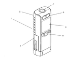
- FIG. 1 and FIG. 2 are views showing the appearance of the drug injection device 1 of the present embodiment.
- FIG. 3 is a diagram illustrating an internal configuration of the pharmaceutical injection device 1 according to the present embodiment.
- the user performs, for example, injection of growth hormone once a day using the drug injection device 1 of FIG.
- the drug injection device 1 of this embodiment includes a cylindrical main body case 2.
- One end side (lower end side) of the main body case 2 is configured so that the injection needle 3 of FIG. 3 is attached.
- a power button 4 for turning on the drug injection device 1 is provided.
- a medicine injection button 5 for performing injection and a display unit 6 for displaying injection guidance are provided in order from the upper end side to the lower end side.
- the medicine injection button 5 and the display unit 6 are arranged near the power button 4.
- a cartridge holder 7 is provided on one end side (lower end side) of the main body case 2 so as to be freely opened and closed as shown in FIGS.
- a medicine syringe 8 is mounted in the cartridge holder 7. That is, the cartridge holder 7 serves as a storage unit that stores the drug syringe 8.
- the user places the drug syringe 8 in the cartridge holder 7 as shown in FIG. 1 and closes the cartridge holder 7 as shown in FIG.
- a piston 9 is provided inside the main body case 2 behind the medicine syringe 8 as shown in FIG.
- the piston 9 is provided so as to be movable with respect to the drug syringe 8.
- the piston 9 is driven by a drive mechanism 20 including a piston feed screw 10, a gear 11, and a motor 12. Then, when the injection needle 3 is mounted in front of the drug syringe 8 and the piston 9 is moved forward (lower end side) by the drive mechanism 20 in a state where the injection needle 3 is inserted into the skin, Drugs are injected into the human body.
- FIG. 3 shows a battery 13 for supplying power to each part.
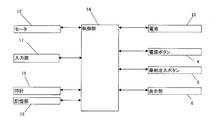
- FIG. 4 shows an electrical connection state of each part.
- the motor 12 constituting the drive mechanism 20 is connected to the control unit 14, and the control unit 14 is configured to drive the motor 12.
- the control unit 14 and the storage unit 15 are configured by an electric circuit.
- the control unit 14 is electrically connected to the power button 4, the medicine injection button 5, the display unit 6, the battery 13, the storage unit 15, and the clock 16 described above.
- an input unit 17 for performing various operations by the patient is electrically connected to the control unit 14.
- the input unit 17 includes a plurality of input buttons.
- the input button may be a mechanical type, but the input button may be displayed with the display unit 6 corresponding to the touch input.
- the control unit 14 performs operation control of each unit illustrated in FIG. 4, and a program for performing the operation control is stored in the storage unit 15. Although the details will be described later, the control unit 14 displays the injection site guidance on the display unit 6.
- the battery 13 is connected to only the control unit 14, but is configured to supply power to each unit shown in FIG.
- the control unit 14, the storage unit 15, and the timepiece 16 are each configured by an electric circuit, and are provided on a control board (not shown) in the main body case 2.
- the control unit 14 has a display control unit 100 (see FIG. 9 described later) that controls the display unit 6.
- the display control unit 100 causes the display unit 6 to display the injection site described below.
- the control part 14 has the calculation part 101, the determination part 102, and the update part 103 as a structure in connection with the display of an injection site
- the display control unit 100, the calculation unit 101, the determination unit 102, and the update unit 103 will be described later.
- the feature of the pharmaceutical injection device 1 of the present embodiment is that the display unit 6 displays a plurality of injection sites, and at least two injection sites are suitable for injection.
- a selectable display indicating that it is a site (that is, an injection site for which injection is recommended) is displayed, and the patient is allowed to select an injection site.
- An injection site suitable for injection (that is, an injection site for which injection is recommended) is an injection site that is unlikely to cause problems due to continuous injection even if this injection site is injected this time. That is, injection at this injection site can prevent an injection site reaction that becomes swollen or ugly. This will be specifically described below.
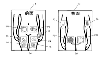
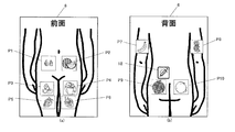
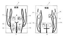
- the display control unit 100 displays a human body diagram on the display unit 6 as shown in FIG. 5, and the human body diagram has at least three injection sites (this time 10 injection sites). P1 to P10) are displayed. It should be noted that the human body diagram can be switched between the front display in FIG. 5A and the rear display in FIG. 5B by operating a display switching button provided in the input unit 17 in FIG.
- the injection site is a selectable display (A1 to A10 in FIG. 7 to be described later) indicating that the site is suitable for injection, or a site that is not suitable for injection (that is, injection is not recommended). Is displayed (B1 to B4 in FIG. 8 to be described later). With these displays, the location of the injection site is specified on the human body diagram of the display unit 6.
- the display control unit 100 displays the fruits of fruits A1 to A10 shown in FIG. 7 as selectable displays on the injection sites P1 to P10 shown in FIG. That is, the fruit of fruit shows that this part is an injection part suitable for injection, and shows that it is a part that hardly causes a problem due to continuous injection.
- the selectable display is displayed by fruit fruits at at least two or more injection sites, so that the patient can select his / her injection from among the injection sites P1 to P10 where the fruit fruits are displayed.
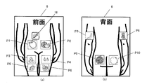
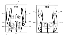
- the display of this injection site P4 is changed from the fruit of the mandarin orange to the type of mandarin orange (selected display, see B1 in FIG. 8 described later) as shown in FIG. 6 (a). . That is, after the injection, the display control unit 100 of the present embodiment changes the selectable display of the selected one injection site to the selected display indicating that the injection to the site is inappropriate (not recommended). To display.
- the patient can recognize that “the injection site cannot be injected today” by looking at the selected display, so that the same injection site is not continuously selected. As a result, it is possible to make it difficult to cause problems due to continuous injection to the same site.
- at least three or more injection sites are set, even if one site has been selected, it is possible to select from the remaining two or more (that is, plural) injection sites.
- the display control unit 100 of the present embodiment performs a display (display that assumes the time) indicating the time when the selected injection site can be selected next as the selected display.
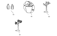
- the growth state of the fruit displayed at the selected injection site is set, for example, as the seed of the image B1 in FIG. , The young tree of the image B3, the flower of the image B4, and the fruits A1 to A10 of FIG.
- the images B1 to B4 and fruits A1 to A10 are stored in the storage unit 15.
- Images B1 to B4 from the seed to the flower are used as a selected display and indicate that the site cannot be injected yet. These selected display images are prepared for each of the fruits A1 to A10 and stored in the storage unit 15.
- the images of fruits A1 to A10 are images of fruits that have been harvested, and are used for selection display. This display indicates that the site is an injection site suitable for injection.
- the fruit at the selected injection site is displayed with a seed indicating the initial planting state. Then, based on the passage of the number of days from this injection site selection date (also referred to as “administration date” or “injection date”), the display is performed step by step from the seed in the initial planting state to the harvested state. For this reason, every day from the injection date, the growth state is displayed to seeds, buds, young trees, flowers, fruits, so that the patient can intuitively understand that the day on which injection is possible is approaching, You can enjoy daily treatment while enjoying your growth.
- FIG. 9 is a diagram showing a control block for displaying an injection site.
- the control unit 14 includes a display control unit 100, a calculation unit 101, a determination unit 102, and an update unit 103.
- the display control unit 100 controls the display of the display unit 6 based on the input from the input unit 17, the information stored in the storage unit 15, the calculation result by the calculation unit 101, and the like.
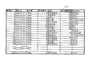
- the storage unit 15 stores an information table T1 shown in FIG. 12, which will be described later, and images A1 to A10 and B1 to B4 shown in FIGS. Although the information table T1 will be described later in detail, the information table T1 has information regarding the injection site.
- the calculation unit 101 calculates the number of days elapsed from the administration date at each injection site P1 to P10 from the data stored in the storage unit 15 and the clock 16. In addition, when an injection site is selected from the injection sites P1 to P10 when performing injection, the calculation unit 101 calculates the number of days that have elapsed from the drug administration date for the selected injection site.
- the determination unit 102 determines whether each of a plurality of injection sites is a site suitable for injection.
- a selected display for example, image B1 to image B4
- indicating that it is unsuitable for injection is displayed at the injection site determined to be unsuitable for injection by the determination unit 102.
- a selectable display for example, images A1 to A10 is displayed on the injection site determined by the determination unit 102 as the site suitable for injection.
- the determination unit 102 calculates a stage for displaying an item from the elapsed days calculated by the calculation unit 101 and a dosing interval set in advance by a doctor or the like. Determine whether to perform. Moreover, the determination part 102 determines whether the injection site is a site suitable for injection from the elapsed days calculated for the selected injection site and the administration interval. If the region is not suitable for injection, the display control unit 100 causes the display unit 6 to display a warning.
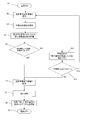
- FIGS. 10 and 11 are flowcharts for explaining the display of the display unit 6, and this program is executed by the configuration in the control unit 14.
- the power button 4 is operated by the patient at the time of injection, the power of the drug injection device 1 is turned on (S1 in FIG. 10).
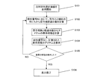
- the display control unit 100 displays an injection site selection screen on the display unit 6 as illustrated in FIG. Details of the operation of S2 in FIG. 10 will be described using the operation flowchart of FIG. (Injection site selection screen display process)
- the display control unit 100 displays the front of the human body.
- the processing of S102 to S105 in FIG. 11 is performed for each injection site P1 to P6, and the growth state of the fruit is displayed.
- the display control unit 100, the calculation unit 101, and the determination unit 102 read information corresponding to the injection sites P1 to P10 from the information table T1 of FIG.
- This information table T1 holds the following five pieces of information regarding the injection sites P1 to P10, and is stored in the storage unit 15.
- Site number Indicates the injection site. Corresponds to injection sites P1 to P10.
- Name Indicates the name of the injection site.
- Administration interval Indicates the interval at which a drug is administered. The number of days until the next injection is possible. It is determined so that an injection site reaction is unlikely to occur. That is, it is determined to prevent injection site reaction. Varies depending on the injection site. Determined by a doctor.
- Date of administration Shows the date of administration of the previous drug. Also called the day of injection.
- Item Fruits to be displayed at the injection sites P1 to P10. Fruits A1 to A10 in FIG.
- the site number is 1, the name is right stomach, the administration interval is 5 days, the administration date is not recorded, and the item is an apple.
- the number of injection sites and the administration interval are set so that a selectable display is displayed at least at two or more injection sites.
- the determination unit 102 determines, for each injection site, whether or not the injection site is a site suitable for injection, and the display control unit 100 performs selected display or selectable display. This will be specifically described below.
- the calculation unit 101 calculates the number of elapsed days (that is, how many days have passed since the administration date) from the administration date and the current date of the clock 16 in the part number 1 (S102 in FIG. 11).
- This S102 corresponds to an example of a calculation process.
- the number of days elapsed is set in advance as, for example, 100 days larger than the administration interval (for example, 5 days). As a result, this injection site is in a state suitable for injection since a sufficient number of days have passed.
- the determination unit 102 calculates the item display stage from the administration interval and the elapsed days (S103 in FIG. 11).
- This S103 corresponds to an example of a determination process.
- the administration interval is 5 days
- the number of days elapsed is 1 day (the day after the injection)
- the number of days until the injection is 4 days
- the display stage is determined to be 1 seed.
- the number of days elapsed is 2 days (2 days after the injection)
- 3 days until the injection and the display stage is determined to be 2 buds.
- the display stage is determined to be 3 young trees.
- the display stage is determined to be 4 flowers since 1 day until injection.
- the display control unit 100 extracts an image corresponding to the item display stage from the storage unit 15 and displays the extracted image at the position of the part number. For example, the display control unit 100 takes out an apple fruit image from the storage unit 15 and displays the apple fruit image on the injection site P1 as shown in FIG. 5A (S104 in FIG. 11). This S104 corresponds to an example of a display process.
- the injection sites P1 to P6 are performed.
- Each fruit is displayed in its growing state. This display guides the injection site to the patient (S106 in FIG. 11). That is, the selected display or the selectable display is determined and displayed for each injection site P1 to P6.
- the fruit of the harvested fruit is displayed at the injection sites P1 to P10, so that the patient can visually recognize that the injection site can be selected.
- the patient can select a site where he / she can easily inject from the sites where the fruit of the fruit is displayed.
- the display control unit 100 displays an injection selection icon 18 on the display unit 6, and in the vicinity of the injection sites P1 to P6 according to the selection operation of the input unit 17 by the patient. Move in order. For example, when the determination operation is performed at the input unit 17 while the injection selection icon 18 is displayed in the vicinity of “mandarin orange”, the injection site P4 is selected (S3 in FIG. 10).
- the calculation unit 101 refers to the information table T1 in FIG. 12, and calculates the number of days elapsed after drug administration from the administration date of the injection site P4 and the current date of the clock 16 (S4 in FIG. 10).
- the determination unit 102 determines whether the injection site is a site suitable for injection from the elapsed days and the administration interval. Here, when the portion where the fruit of fruit is displayed is selected, the number of days elapsed is larger than the administration interval of the injection site P4, and the date has passed sufficiently from the administration date (S5 in FIG. 10).
- the unit 100 displays an injection preparation completion screen (not shown) (S6 in FIG. 10).
- the patient injects into the injection site P4 selected by the patient (S7 in FIG. 10). Since this injection process (drug administration process) is the same as the conventional process, a detailed description thereof will be omitted.
- the control unit 14 controls the drug administration.
- the motor 12 is driven to move the piston 9 forward through the gear 11.
- the medicine in the medicine syringe 8 is administered to the human body via the injection needle 3.
- the updating unit 103 updates the administration date and the item in the information table T1 of the site (for example, injection site P4) injected this time.
- the administration date is updated with today's date, and the item is updated with an item randomly selected from the fruits A1 to A10 in FIG. 7 (S8 in FIG. 10).
- a series of injection operations is completed (S9 in FIG. 10).
- the injection site P4 is selected as the injection site P4 as shown in FIG. 6 (a) by the processing operation from S1 to S11 in FIG. As a selected display indicating “”, fruit seeds (see B1 in FIG. 8) are displayed. The patient sees the selected display, recognizes that “this site cannot be injected today”, and selects the injection site from the remaining injection sites P1 to P3 and P5 to P10.
- the display control unit 100 of the present embodiment updates the items in the information table T1 after the injection, and makes the fruit to be selected and displayed different from the fruit before the injection (before the selection). For example, the selected fruit to be displayed is changed from mandarin orange to melon.
- the fruit at the injection site is changed at each injection, and the patient can continue the treatment while having fun saying, "What kind of fruit will this be?"
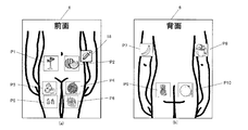
- the injection site P4 the growth state of the buds of FIG. 13 (a), the young tree of FIG. 14 (a), the flowers of FIG. 15 (a), and the fruit is changed and displayed every day.
- the injection site P4 can be injected again.
- the determination unit 102 calculates the progress calculated by the calculation unit 101 in S5 of FIG.
- the number of days elapsed is compared with the administration interval by comparing the number of days with the administration interval.
- the display control unit 100 displays a warning on the display unit 6 that “It is a part where the administration interval has not elapsed” (S10 in FIG. 10).
- the display control unit 100 displays “Do you want to change the injection site?” On the display unit 6 (S11 in FIG. 10), and when the input unit 17 is operated to change the injection site, the display control unit 100 changes to S2 in FIG. Control is returned and the injection site is selected again. In addition, there are times when the selected and displayed part is selected. For example, when the fruit cannot be injected into the fruit injection site due to injury. In such a case, after a warning is displayed in S10 of FIG. 10, the forced injection operation of the input unit 17 is performed in S11 of FIG. 10, thereby transferring the control to S6 of FIG. Can do.
- the display control unit 100 displays at least three or more injection sites, and displays a selectable display on at least two or more injection sites among them so that the injection sites can be selected. For this reason, even if there is an injection site that has been selected, the patient can always select a site to be injected from two or more injection sites.
- the display control unit 100 of the present embodiment displays a selectable display on all injection sites suitable for injection.
- 5 (a) and 5 (b) fruit fruits are displayed as selectable displays at the injection sites P1 to P10.
- all injection sites suitable for injection can be visually recognized by the patient, and the range of patient selection is expanded.
- a drug administration interval is set according to the injection site reaction, and the seed in the initial planting state is set corresponding to this administration interval.
- the number of days to change from (selected display) to the actual harvest status (selectable display) is set.
- images from seeds to reals are stored in the storage unit 15 in a state corresponding to the number of days changed.
- the display control unit 100 displays at least two positions of the abdomen, legs, and arms and the buttocks as injection sites displayed on the display unit 6.
- the display on the buttocks is set to 3 days from the seed to the fruit, for example, and is less than the number of days (for example, 5 days) from the seed to the fruit on the belly, legs and arms. That is, since the buttocks is a site where injection site reaction is difficult to occur, the number of days to be changed was set smaller than other sites. Thereby, it is possible to select the buttocks faster than other parts.
- the drug injection device 1 includes a main body case 2, a piston 9, a drive mechanism 20, a display unit 6, and a control unit 14.
- the main body case 2 has a cartridge holder 7 (an example of a drug syringe mounting part) to which the drug syringe 8 is mounted.
- the piston 9 is provided so as to be movable with respect to the medicine syringe 8 attached to the cartridge holder 7.
- the drive mechanism 20 drives the piston 9.
- the display unit 6 displays the injection sites P1 to P10 for injecting the drug in the drug syringe 8.
- the display control unit 100 displays a plurality of injection sites P1 to P10 on the display unit 6, and at least two or more injection sites indicate a selectable display (A1) indicating that the injection sites are sites suitable for injection (A1). To A10) are displayed.
- the patient can select a site where his / her injection can be easily performed from among the injection sites displayed as selectable.
- the site selected by the user becomes an injection site suitable for injection, that is, a site that hardly causes a problem due to continuous injection. For this reason, even if a patient is a child, it can guide to inject
- the display control unit 100 displays a selectable display on all injection sites suitable for injection. This allows the patient to select from more injection sites.
- the display control unit 100 does not display a selectable display of one selected injection site (for example, A5 of the injection site P4 in FIG. 5A) after injection. Is changed to the selected display (B1 of the injection site P4 in FIG. 6A). As a result, the patient can easily recognize the site of injection.
- the display control unit 100 performs a display indicating when the selected injection site can be selected next as the selected display.
- the display indicating the time for example, the display of B1 to B4 in FIG. 8 is performed.
- the display of the seed of B1 is performed, the patient can recognize that it is immediately after the injection, and when the display of the flower of B4 is performed, the patient can recognize that the injection is soon possible. .
- the display control unit 100 displays the article displayed at the selected injection site so as to indicate when the selected injection site can be selected next as the selected display. Display the growth status of. By displaying as B1 to B4 in FIG. 8 of the present embodiment, the patient can easily confirm the time when injection is possible.
- the display control unit 100 displays the fruits for each of the injection sites P1 to P10, sets the fruits at the selected injection site as the initial planting state, and starts the selected selection date.
- the display is changed from the initial planting state to the harvested state based on the passage of days. With such a display, even a child can easily confirm the injection site, and can make an injection while enjoying the fruit growth process.
- the display control unit 100 displays different fruits for each of the injection sites P1 to P10. This makes it easier for the patient to determine the injection site. Patients can continue treatment while enjoying the growth of various fruits.
- the display control unit 100 makes the fruit to be selected and displayed different from the fruit before selection.
- the patient does not know which fruit (A1 to A10) is displayed through the images B1 to B4, daily injection can be performed while looking forward to fruit growth.
- the number of days to be changed from the selected display to the selectable display is set for each injection site P1 to P10 displayed on the display unit 6. Thereby, the number of days to be changed can be set to be smaller than other sites for sites where injection site reaction is difficult to occur.
- the display control unit 100 causes the display unit 6 to display at least two abdomen, legs, and arms and the buttocks as injection sites, and the number of days of change in the buttocks is the abdomen. Is set to be less than the number of days of change in the legs and arms. Since the buttocks is a site where injection site reaction is difficult to occur, the number of days to be changed can be set smaller than other sites, and the buttocks can be selected earlier than other sites.
- the drug injection device 1 further includes a determination unit 102.
- the determination unit 102 determines whether each of the plurality of injection sites P1 to P10 is a site suitable for injection.
- the display control unit 100 displays selectable indications (A1 to A10 in FIG. 7) on the injection sites (P1 to P10) determined by the determination unit 102 as sites suitable for injection. Thereby, the patient can select the site
- the site selected by the user becomes an injection site suitable for injection, that is, a site that hardly causes a problem due to continuous injection.
- the display control unit 100 displays a selected display (in FIG. 8) indicating that it is unsuitable for injection at the injection site determined by the determination unit 102 as being unsuitable for injection. B1 to B4) are displayed. Thus, a selected display and a selectable display can be performed.
- the pharmaceutical injection device 1 further includes a storage unit 15, an update unit 103, and a calculation unit 101.
- the storage unit 15 stores information related to the drug administration date on which each injection site (P1 to P10) is selected and injection is performed.
- the update unit 103 updates the information related to the drug administration date at one selected injection site after the injection.
- the calculation unit 101 calculates the elapsed period from the drug administration date.
- the determination unit 102 determines, for each injection site, whether or not the injection site is a site suitable for injection based on the elapsed period from the drug administration date. Thereby, since it can be determined whether the injection site is suitable for injection by the elapsed period from the drug administration date, the occurrence of injection site reaction can be reduced.
- the storage unit 15 stores drug administration intervals set for the respective injection sites P1 to P10, as shown in FIG.
- the determination unit 102 compares the administration interval with the elapsed period from the drug administration date, and determines that the injection site is a site suitable for injection when the elapsed period is longer than the administration interval. If it is shorter than the interval, the injection site is determined to be an unsuitable site. This makes it possible to determine whether or not the injection site is suitable for injection based on the elapsed time from the drug administration date based on the administration interval set in advance by a doctor or the like, thereby reducing the occurrence of injection site reaction. .
- the display control method of the drug injection device 1 is a control method of the drug injection device 1 including the main body case 2, the piston 9, the drive mechanism 20, and the display unit 6, and includes S104 (display).
- the main body case 2 has a cartridge holder 7 (an example of a drug syringe mounting part) to which the drug syringe 8 is mounted.
- the piston 9 is provided so as to be movable with respect to the medicine syringe 8 attached to the cartridge holder 7.
- the drive mechanism 20 drives the piston 9.
- the display unit 6 displays the injection sites P1 to P10 for injecting the drug in the drug syringe 8.
- S104 (an example of a display process) displays a plurality of injection sites P1 to P10 on the display unit 6 and can be selected to indicate that at least two injection sites are suitable for injection. Display the display.
- the selected display uses the fruit growth display as a display for assuming the next selection time for the selected injection site, but is not limited to this.
- An assembly display of an article such as may be used.
- the display control unit 100 displays a flower for each injection site (for example, P1 to P10) and changes the flower at the selected injection site to the initial planting state. It is possible to display and change from the initial planting state to the flowering state of the flower based on the passage of days from the selected date. Naturally, the display control unit 100 displays a different flower for each injection site. Furthermore, the display control unit 100 may make the selected and displayed flowers different from the flowers before selection.
- the display control unit 100 may display, for example, a process for assembling the robot from the feet of the robot toward the head to reach the finished product based on the number of days elapsed.
- the display control unit 100 displays the remaining until the day when the injection can be performed as the selected display.
- the number of days may be displayed. In this case, the patient can recognize the remaining number of days until the day when the injection can be performed by a numerical value.
- an article displayed as selectable display may be divided and displayed so that the next selection time for the selected injection site is assumed.
- the watermelon is divided into three equal parts and displayed so as to be completed in three days. In this configuration, when the article is completed, it can be injected into the injection site.
- the information table T1 is stored in the storage unit 15.
- a medication administration history may be stored.
- the storage unit 15 may store the current administration date of the drug and the site information indicating the selected injection site. Good.
- the administration history table R1 shown in FIG. 19 is stored in the storage unit 15, and the update unit 103 adds the administration date of the current drug and the drug administration information of the injection site to the administration history table R1.
- the update unit 103 uses the history number, the drug administration date, the drug dosage, and the selected injection as the current drug administration information.
- a site number (an example of site information) indicating a site, a name of the site (an example of site information), an administration interval record, and an item of the injection site selected this time are added and stored at the end of the administration history table R1. .
- the administration interval results indicate the administration interval of the drug at each injection site in days, and the calculation unit 101 calculates the current drug administration date and the previous drug administration date at the injection site selected this time. To do. For example, when storing the history number “9” of the administration history table R1, the calculation unit 101 searches the administration history table R1 for previous administration information corresponding to the site number “1” of the injection site selected this time. The part number “1” is stored in the history number “2”. Therefore, the calculation unit 101 compares the current administration date with the previous administration date (administration date of history number “2”), calculates the administration interval of the drug as 7 days, and sets the administration interval to history number “9”. 7 is stored.
- the administration history table R1 is displayed on the display unit 6 so that the number of administrations for each injection site can be known. As a result, the patient and doctor can make an administration plan such as “Let's increase the administration to this site”.
- the injection site is displayed on the display unit 6 of the drug injection device 1, but an injection site display device may be provided separately from the drug injection device.
- Such an injection site display device includes a display unit and a display control unit, and the display control unit displays a plurality of injection sites on the display unit, and at least two or more injection sites are injected. A selectable display indicating that the part is a part suitable for injection is displayed.
- the administration interval differs depending on the injection site, but it may be a fixed interval.
- each of the display control unit 100, the calculation unit 101, and the determination unit 102 extracts information from the storage unit 15.
- an information extraction unit is provided separately, and the display control unit 100, Information may be transmitted to the calculation unit 101 and the determination unit 102.
- the update unit 103 may also serve as an information extraction unit that extracts information from the storage unit 15.
- the display control unit 100 of the present embodiment displays a plurality of injection sites on the display unit 6, and at least two or more injection sites are suitable for injection.
- a selectable display showing is displayed. For this reason, since a selectable display is displayed at least at two or more injection sites, the patient can select a site where the patient can easily inject from the selectable displayed injection sites each time.
- the site selected by the user becomes an injection site suitable for injection, that is, a site that hardly causes a problem due to continuous injection.
- medical agent injection apparatus of this invention the control method of a chemical
Landscapes
- Health & Medical Sciences (AREA)
- Engineering & Computer Science (AREA)
- Biomedical Technology (AREA)
- General Health & Medical Sciences (AREA)
- Public Health (AREA)
- Primary Health Care (AREA)
- Medical Informatics (AREA)
- Epidemiology (AREA)
- Vascular Medicine (AREA)
- General Business, Economics & Management (AREA)
- Business, Economics & Management (AREA)
- Life Sciences & Earth Sciences (AREA)
- Veterinary Medicine (AREA)
- Animal Behavior & Ethology (AREA)
- Anesthesiology (AREA)
- Hematology (AREA)
- Heart & Thoracic Surgery (AREA)
- Dermatology (AREA)
- Chemical & Material Sciences (AREA)
- Bioinformatics & Cheminformatics (AREA)
- Medicinal Chemistry (AREA)
- Infusion, Injection, And Reservoir Apparatuses (AREA)
Abstract
Priority Applications (3)
| Application Number | Priority Date | Filing Date | Title |
|---|---|---|---|
| EP15773432.8A EP3127569B1 (fr) | 2014-04-01 | 2015-03-23 | Dispositif pharmaceutique d'injection, procédé de commande d'affichage pour dispositif pharmaceutique d'injection, et dispositif d'affichage de site d'injection |
| US15/119,705 US10596331B2 (en) | 2014-04-01 | 2015-03-23 | Pharmaceutical injecting device, display control method for pharmaceutical injecting device, and injection site display device |
| JP2016511552A JP6310546B2 (ja) | 2014-04-01 | 2015-03-23 | 薬剤注入装置、薬剤注入装置の表示制御方法および注射部位表示装置 |
Applications Claiming Priority (2)
| Application Number | Priority Date | Filing Date | Title |
|---|---|---|---|
| JP2014-075597 | 2014-04-01 | ||
| JP2014075597 | 2014-04-01 |
Publications (1)
| Publication Number | Publication Date |
|---|---|
| WO2015151900A1 true WO2015151900A1 (fr) | 2015-10-08 |
Family
ID=54240228
Family Applications (1)
| Application Number | Title | Priority Date | Filing Date |
|---|---|---|---|
| PCT/JP2015/058747 Ceased WO2015151900A1 (fr) | 2014-04-01 | 2015-03-23 | Dispositif d'injection de médicament, procédé de commande d'affichage pour dispositif d'injection de médicament, et dispositif d'affichage de site d'injection |
Country Status (4)
| Country | Link |
|---|---|
| US (1) | US10596331B2 (fr) |
| EP (1) | EP3127569B1 (fr) |
| JP (1) | JP6310546B2 (fr) |
| WO (1) | WO2015151900A1 (fr) |
Cited By (5)
| Publication number | Priority date | Publication date | Assignee | Title |
|---|---|---|---|---|
| RU2732830C2 (ru) * | 2015-11-30 | 2020-09-23 | Санофи-Авентис Дойчланд Гмбх | Упаковочный узел |
| US11103633B2 (en) | 2015-11-30 | 2021-08-31 | Sanofi-Aventis Deutschland Gmbh | Packaging assembly with mounting attachment |
| US11369732B2 (en) | 2017-02-24 | 2022-06-28 | Sanofi | Packaging assembly |
| US11565034B2 (en) | 2017-02-24 | 2023-01-31 | Sanofi | Packaging assembly |
| JP2025530927A (ja) * | 2022-09-02 | 2025-09-18 | イーライ リリー アンド カンパニー | 注入部位不具合検出 |
Families Citing this family (7)
| Publication number | Priority date | Publication date | Assignee | Title |
|---|---|---|---|---|
| CA2895103A1 (fr) * | 2015-06-25 | 2016-12-25 | Montmed Inc | Aiguilles-stylo colorees, trousse et methode d'utilisation associee |
| GB2606087B (en) | 2016-06-06 | 2023-03-08 | E3D Agricultural Cooporative Association Ltd | Multiple use computerized injector |
| US11367532B2 (en) | 2016-10-12 | 2022-06-21 | Embecta Corp. | Integrated disease management system |
| US10569020B2 (en) | 2016-11-29 | 2020-02-25 | Portal Instruments, Inc. | Method and device for delivering a subcutaneous dose through multiple injections |
| CA3187718A1 (fr) * | 2020-07-31 | 2022-02-03 | Ryan Francis Bedell | Systeme et procede de suivi d'informations de site d'injection |
| US20220105282A1 (en) * | 2020-10-02 | 2022-04-07 | Bigfoot Biomedical, Inc. | Injection site determination systems and methods for injection site tracking and recommending injection sites |
| CN113209424A (zh) * | 2021-05-17 | 2021-08-06 | 嘉兴市第一医院 | 一种智能化胰岛素注射精准定位多功能盒及其控制系统 |
Citations (5)
| Publication number | Priority date | Publication date | Assignee | Title |
|---|---|---|---|---|
| JP2010534552A (ja) * | 2007-07-27 | 2010-11-11 | マイルストーン サイエンティフィック インコーポレイテッド | 自己投与注射システム |
| US20110009812A1 (en) * | 2009-07-07 | 2011-01-13 | Relox Medical, Llc | Method and apparatus for syringe injection of fluids |
| JP3171571U (ja) * | 2011-04-26 | 2011-11-10 | 純哉 田中 | チューブ及びラベル |
| WO2012105577A1 (fr) * | 2011-02-01 | 2012-08-09 | 株式会社根本杏林堂 | Dispositif d'injection de solution de médicament |
| WO2013038639A1 (fr) * | 2011-09-12 | 2013-03-21 | パナソニック株式会社 | Dispositif d'injection de médicament |
Family Cites Families (9)
| Publication number | Priority date | Publication date | Assignee | Title |
|---|---|---|---|---|
| ES2555125T3 (es) | 2004-02-18 | 2015-12-29 | Ares Trading S.A. | Dispositivo manual de inyección controlada electrónicamente para inyectar medicamentos líquidos |
| US20090177154A1 (en) * | 2008-01-08 | 2009-07-09 | Michael Blomquist | Insulin pump with convenience features |
| US8113845B2 (en) | 2009-02-11 | 2012-02-14 | Koster Erika S | Method and system for maintaining injection reminders via stuffed doll |
| FR2980977A1 (fr) | 2011-10-05 | 2013-04-12 | Eric Szatkowski | Dispositif electronique permettant d'indiquer et d'alterner les zones d'injection de produits medicamenteux |
| US9550029B2 (en) | 2012-10-30 | 2017-01-24 | Elwha Llc | Systems and methods for guiding injections |
| JP3184481U (ja) | 2013-04-18 | 2013-06-27 | 帝人エージェンシー株式会社 | 注射器ホルダー |
| CA2928661C (fr) * | 2013-11-01 | 2022-05-31 | Becton, Dickinson And Company | Dispositif d'injection concu pour correspondre a un dispositif mobile |
| EP3077028A4 (fr) | 2013-12-04 | 2017-08-16 | Becton, Dickinson and Company | Systèmes, appareils et procédés pour encourager la rotation d'un site d'injection et prévenir la lipodystrophie due à des injections répétées dans une zone du corps |
| WO2015136564A1 (fr) * | 2014-03-10 | 2015-09-17 | Osvaldo Tufi | Module d'extension de surveillance et de contrôle d'observance d'une thérapie pour des médicaments injectables contenus dans des seringues préremplies |
-
2015
- 2015-03-23 EP EP15773432.8A patent/EP3127569B1/fr active Active
- 2015-03-23 JP JP2016511552A patent/JP6310546B2/ja active Active
- 2015-03-23 US US15/119,705 patent/US10596331B2/en active Active
- 2015-03-23 WO PCT/JP2015/058747 patent/WO2015151900A1/fr not_active Ceased
Patent Citations (5)
| Publication number | Priority date | Publication date | Assignee | Title |
|---|---|---|---|---|
| JP2010534552A (ja) * | 2007-07-27 | 2010-11-11 | マイルストーン サイエンティフィック インコーポレイテッド | 自己投与注射システム |
| US20110009812A1 (en) * | 2009-07-07 | 2011-01-13 | Relox Medical, Llc | Method and apparatus for syringe injection of fluids |
| WO2012105577A1 (fr) * | 2011-02-01 | 2012-08-09 | 株式会社根本杏林堂 | Dispositif d'injection de solution de médicament |
| JP3171571U (ja) * | 2011-04-26 | 2011-11-10 | 純哉 田中 | チューブ及びラベル |
| WO2013038639A1 (fr) * | 2011-09-12 | 2013-03-21 | パナソニック株式会社 | Dispositif d'injection de médicament |
Non-Patent Citations (1)
| Title |
|---|
| See also references of EP3127569A4 * |
Cited By (15)
| Publication number | Priority date | Publication date | Assignee | Title |
|---|---|---|---|---|
| US11951274B2 (en) | 2015-11-30 | 2024-04-09 | Sanofi-Aventis Deutschland Gmbh | Packaging assembly |
| US12115336B2 (en) | 2015-11-30 | 2024-10-15 | Sanofi-Aventis Deutschland Gmbh | Packaging assembly |
| US11103633B2 (en) | 2015-11-30 | 2021-08-31 | Sanofi-Aventis Deutschland Gmbh | Packaging assembly with mounting attachment |
| US11103632B2 (en) | 2015-11-30 | 2021-08-31 | Sanofi-Aventis Deutschland Gmbh | Packaging assembly |
| US11278660B2 (en) | 2015-11-30 | 2022-03-22 | Sanofi-Aventis Deutschland Gmbh | Packaging assembly with mounting attachment |
| US12133964B2 (en) | 2015-11-30 | 2024-11-05 | Sanofi-Aventis Deutschland Gmbh | Packaging assembly |
| RU2734912C2 (ru) * | 2015-11-30 | 2020-10-26 | Санофи-Авентис Дойчланд Гмбх | Упаковочный узел |
| RU2732830C2 (ru) * | 2015-11-30 | 2020-09-23 | Санофи-Авентис Дойчланд Гмбх | Упаковочный узел |
| US11565034B2 (en) | 2017-02-24 | 2023-01-31 | Sanofi | Packaging assembly |
| US11944777B2 (en) | 2017-02-24 | 2024-04-02 | Sanofi | Packaging assembly |
| US11724021B2 (en) | 2017-02-24 | 2023-08-15 | Sanofi | Packaging assembly |
| US11369732B2 (en) | 2017-02-24 | 2022-06-28 | Sanofi | Packaging assembly |
| US12397102B2 (en) | 2017-02-24 | 2025-08-26 | Sanofi | Packaging assembly |
| US12427242B2 (en) | 2017-02-24 | 2025-09-30 | Sanofi | Packaging assembly |
| JP2025530927A (ja) * | 2022-09-02 | 2025-09-18 | イーライ リリー アンド カンパニー | 注入部位不具合検出 |
Also Published As
| Publication number | Publication date |
|---|---|
| EP3127569A1 (fr) | 2017-02-08 |
| US20170056605A1 (en) | 2017-03-02 |
| JP6310546B2 (ja) | 2018-04-11 |
| EP3127569B1 (fr) | 2018-06-13 |
| EP3127569A4 (fr) | 2017-04-26 |
| JPWO2015151900A1 (ja) | 2017-04-13 |
| US10596331B2 (en) | 2020-03-24 |
Similar Documents
| Publication | Publication Date | Title |
|---|---|---|
| JP6310546B2 (ja) | 薬剤注入装置、薬剤注入装置の表示制御方法および注射部位表示装置 | |
| EP2948204B1 (fr) | Dispositifs et procédés de sécurité pharmaceutique | |
| EP3062865B1 (fr) | Dispositif d'injection conçu pour correspondre à un dispositif mobile | |
| US10058657B2 (en) | Injection devices with ergonomic enhancements | |
| JP5938415B2 (ja) | 薬用モジュール(medicatedmodule)を備えた自動注射デバイス | |
| US20100251114A1 (en) | Digital interface for a medical device | |
| TW201200190A (en) | Electro-mechanical drug delivery device | |
| JP2014507223A (ja) | 2つまたはそれ以上の薬剤を送達する薬物送達デバイスと共に使用される投薬インターフェース | |
| JP2016182430A (ja) | 流体投与装置 | |
| WO2008019013A3 (fr) | Interface pour pompe à perfusion médicale | |
| EP2507690A1 (fr) | Système d'écran tactile amélioré et procédés de navigation et de programmation pour une pompe d'injection | |
| MX2012010831A (es) | Dispositivo y metodo para determinar informacion relacionada con un dispositivo medico. | |
| EA034009B1 (ru) | Инъекционное устройство | |
| JP5764660B2 (ja) | 薬剤注入装置 | |
| JP5898612B2 (ja) | 薬物送達デバイス用の投与ボタン及び投与ボタンの製造方法 | |
| KR20250130628A (ko) | Pca 펌프 프로그래밍 및 환자 병력 사용자 인터페이스 | |
| JP2015139485A (ja) | 薬剤注入装置 | |
| WO2018061560A1 (fr) | Dispositif d'administration de médicament liquide, système d'assistance d'administration de médicament liquide et procédé d'assistance d'administration de médicament liquide | |
| TWI381862B (zh) | Method and method of hand - push intravenous injection of pharmacokinetic model | |
| CN120226091A (zh) | 自动注射器泵近空警报激活阈值编程 | |
| WO2026015719A1 (fr) | Interface utilisateur aux fins d'une programmation de pompe pca pour éviter des erreurs de dose | |
| CN121752312A (zh) | 大容积可穿戴药物输送装置 | |
| JP2015181555A (ja) | 送液ポンプ | |
| Serbin | Building solidarity in disease communities’ quest for better care and treatments: a conversation with a young tennis award-winner |
Legal Events
| Date | Code | Title | Description |
|---|---|---|---|
| 121 | Ep: the epo has been informed by wipo that ep was designated in this application |
Ref document number: 15773432 Country of ref document: EP Kind code of ref document: A1 |
|
| ENP | Entry into the national phase |
Ref document number: 2016511552 Country of ref document: JP Kind code of ref document: A |
|
| WWE | Wipo information: entry into national phase |
Ref document number: 15119705 Country of ref document: US |
|
| REEP | Request for entry into the european phase |
Ref document number: 2015773432 Country of ref document: EP |
|
| NENP | Non-entry into the national phase |
Ref country code: DE |