WO2015151996A1 - 電子機器 - Google Patents
電子機器 Download PDFInfo
- Publication number
- WO2015151996A1 WO2015151996A1 PCT/JP2015/059376 JP2015059376W WO2015151996A1 WO 2015151996 A1 WO2015151996 A1 WO 2015151996A1 JP 2015059376 W JP2015059376 W JP 2015059376W WO 2015151996 A1 WO2015151996 A1 WO 2015151996A1
- Authority
- WO
- WIPO (PCT)
- Prior art keywords
- rotating member
- electret
- center
- electrode
- power generation
- Prior art date
- Legal status (The legal status is an assumption and is not a legal conclusion. Google has not performed a legal analysis and makes no representation as to the accuracy of the status listed.)
- Ceased
Links
Images







Classifications
-
- H—ELECTRICITY
- H02—GENERATION; CONVERSION OR DISTRIBUTION OF ELECTRIC POWER
- H02N—ELECTRIC MACHINES NOT OTHERWISE PROVIDED FOR
- H02N1/00—Electrostatic generators or motors using a solid moving electrostatic charge carrier
- H02N1/06—Influence generators
- H02N1/08—Influence generators with conductive charge carrier, i.e. capacitor machines
-
- G—PHYSICS
- G04—HOROLOGY
- G04C—ELECTROMECHANICAL CLOCKS OR WATCHES
- G04C10/00—Arrangements of electric power supplies in time-pieces
-
- G—PHYSICS
- G04—HOROLOGY
- G04G—ELECTRONIC TIME-PIECES
- G04G19/00—Electric power supply circuits specially adapted for use in electronic time-pieces
Definitions
- the present invention relates to an electronic device with a power generation function.
- a small portable electronic device such as a wristwatch is equipped with a power generation function in order to save the trouble of battery replacement.
- power generation mechanisms used in such electronic devices, and those using the principle of vibration power generation using electrets have been proposed.
- Patent Document 1 describes a power generation device used in a portable electric device, in which an electrode that rotates integrally with a rotating weight supported by a spiral spring is disposed opposite to an electret film.
- Rotational power generators using the above-described electrets are mounted on portable electronic devices, and are intended to generate power by changing the posture of the electronic devices while being carried.
- Patent Document 1 when the electrode is connected and supported in the order of the rotary weight, the spiral spring, and the fixing member, the spiral spring is wound up or extended depending on the change in the attitude of the electronic device. Therefore, there is a concern that the rotational movement of the electrode cannot be performed.
- the natural angular frequency of the rotational motion of the electrode is uniquely determined by the spring constant of the spiral spring and the mass elastically supported by the spiral spring.
- the present invention has been made in view of such circumstances, and an object thereof is to prevent the spiral spring from being rolled up and stretched in an electronic device equipped with a rotating power generation device using an electret. Further, an additional problem of the present invention is to efficiently generate power with respect to vibrations of various periods given from the outside in an electronic device equipped with a rotating power generation device using an electret.
- At least one first rotating member supported so as to be freely rotatable and having a center of gravity deviated from the center of rotation, at least one second rotating member supported so as to be freely rotatable, and the first rotating member.
- an elastic member that elastically connects the second rotating member to each other with respect to the rotational movement thereof, and a fixing member provided to face the second rotating member, and the second rotating member and the
- An electronic apparatus including a power generation mechanism in which an electret film is provided on any surface of a fixing member.
- the value of the moment of inertia of the first rotating member is different from the value of the moment of inertia of the second rotating member.
- the value of the moment of inertia of the first rotating member is larger than the value of the moment of inertia of the second rotating member.
- the second rotating member is an electronic device whose center of gravity is deviated from the center of rotation.
- a plurality of the second rotating member, the fixing member, and the elastic member are provided, and the plurality of second rotating members are rotated by the elastic member.
- Electronic devices that are elastically connected to each other with respect to movement.
- the frequency of external vibration input can be different from the frequency of rotational vibration of the electrode used for power generation.
- the frequency of rotational vibration of the electrode used for power generation can be made higher than the frequency of external vibration input, and the power generation efficiency is improved.
- kinetic energy can be recovered over a wider range of frequencies against various vibrations given from the outside, and the power generation efficiency is improved.
- the area of the electret film can be increased and a compact configuration can be obtained.
- kinetic energy can be recovered over a wider range of frequencies against various vibrations given from the outside, and the power generation efficiency is improved.
- the power generation mechanism can be reduced in size by reducing the thickness of the power generation mechanism in the rotation axis direction, and the power generation mechanism caused by the spiral spring extending radially outward can be realized. Damage can be suppressed.
- FIG. 1 is a plan view of the electronic apparatus 1 according to the first embodiment of the present invention.
- the electronic device 1 is a wristwatch, but other devices such as a pocket watch or an electronic compass or a communication device may be used.
- the electronic device 1 is scheduled to be equipped with a power generation mechanism that generates electric power using the change in posture of the electronic device 1 itself, so that the posture changes frequently.
- a power generation mechanism that generates electric power using the change in posture of the electronic device 1 itself, so that the posture changes frequently.
- a small portable device is preferable.
- the electronic device 1 is a pointer-type timepiece as shown, and the hour hand, the minute hand, and the second hand are provided coaxially with a pointer shaft 2 disposed at the center of the electronic device 1 as a rotation center.
- the number and arrangement of the pointers are not limited to this and are arbitrary, and may be a so-called digital type that displays information using a liquid crystal display or an organic EL display, and these are combined. It may be a thing.
- the electronic device 1 is not a watch, the electronic device 1 has an appearance corresponding to its function.
- the electronic device 1 accommodates a power generation mechanism, a movement, and a power storage device, which will be described later, inside a case 4, and these mechanisms are arranged behind the dial plate 3 and covered.
- the design of the dial plate 3 illustrated in FIG. 1 is also arbitrary, and the dial plate 3 itself may be transparent or omitted so that the mechanism inside the case 4 can be visually recognized.
- the power generation mechanism is disposed immediately behind the dial 3 as will be described later, the user of the electronic device 1 visually recognizes the power generation mechanism.
- the arrangement of the mechanisms accommodated in the case 4 is also arbitrary.
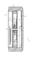
- FIG. 2 is a cross-sectional view of the electronic apparatus 1 according to the present embodiment.
- a movement 5 is accommodated in the case 4, and the power generation mechanism 6 and the dial 3 are arranged in this order on the upper side of the movement 5.
- a power storage device 7 is attached below the movement 5. These mechanisms are inserted into the case 4 from below and are fixed in the case 4 by the back cover 8.
- a pointer shaft 2 extending from the movement 5 protrudes from the center of the dial 3 through the power generation mechanism 6, and each pointer is attached.
- a transparent windshield 9 such as glass is attached to the upper side of the case 4 to protect each pointer and dial.
- the outer diameter of the power generation mechanism 6 in plan view is substantially the same as that of the movement 5, and the power generation mechanism 6 and the movement 5 are stacked in the height direction of the electronic device 1. Is not essential.
- the upper and lower arrangements of the power generation mechanism 6 and the movement 5 may be reversed, or the power generation mechanism 6 may be incorporated as a part of the movement 5.
- the dial 3 is provided on the upper surface of the power generation mechanism 6, and various indications such as time letters are provided on the surface, so that the user of the electronic device 1 has a pointer. The time pointed to can be read.
- the material of the dial 3 is not particularly limited, and synthetic resins, natural materials such as shells and rocks, and various metals may be used.
- the movement 5 is an assembly in which a train wheel and a motor for driving the hands, a clock circuit including a quartz oscillator for measuring time, a controller for controlling the entire electronic device 1 and the like are integrally assembled in a frame called a main plate.
- the movement 5 operates by obtaining electric power from the power storage device 7 attached to the movement 5.
- the power storage device 7 supplies power to the movement 5 and at the same time stores the power generated by the power generation mechanism 6.
- the power storage device 7 is a button-type lithium secondary battery.
- the shape and type of the electricity storage device 7 are not particularly limited, and an electric double layer capacitor such as a lithium ion capacitor may be used in addition to various secondary batteries.
- the power generation mechanism 6 is a rotary power generation device that uses an electret, and rotates the energy of vibration caused by the movement of the arm during walking in a state in which the electronic device 1 is worn on the user's arm, for example. It is taken out as a rotational motion by the weight 10, and the electret electrode 12 is rotationally oscillated through the spiral spring 11, and is recovered as electrical energy from the counter electrode 13.
- the rotary weight 10 is fixed to the hollow shaft 18 rotatably supported by the generator case 16 by the bearing 17 fixed to the generator case 16 and the electret electrode 12 is fixed to the pointer shaft 2. It is supported so that it can rotate freely on the same axis.
- this structure is an example, and if the rotary weight 10 and the electret electrode 12 are each supported so that free rotation is possible, the support method and the position of a rotating shaft will not be limited.
- FIG. 3 is a schematic circuit diagram for explaining the operating principle of the power generation mechanism 6.
- the electret electrode 12 and the counter electrode 13 are arranged to face each other in parallel with a predetermined slight gap, and both move relatively to some extent in the in-plane direction. Is supported so that In the present embodiment, the counter electrode 13 is fixed, and the electret electrode 12 is supported so as to rotate and vibrate in the plane.
- An electret film 14 is formed on the surface of the electret electrode 12 on the counter electrode 13 side so as to be in a predetermined charged state.
- the electret film 14 is charged so that the counter electrode 13 side has a negative charge.
- membrane 14 and the counter electrode 13 are stripe shapes with a substantially equal planar shape, and the state where the electret film
- a material that is easily charged is used as the material of the electret film 14, and examples of the material that is negatively charged include silicon oxide and fluororesin.
- a specific example of such a material is CYTOP (registered trademark), which is a fluororesin manufactured by Asahi Glass Co., Ltd.
- other materials for the electret film 14 include polymer materials such as polypropylene, polyethylene terephthalate, polyvinyl chloride, polystyrene, polytetrafluoroethylene, polyvinyldendifluoride, and polyvinylfluoride, and the aforementioned silicon oxide and silicon nitride. Inorganic materials such as silicon oxynitride can also be used.
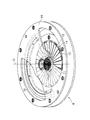
- FIG. 4 is a perspective view of the power generation mechanism 6. From the opening provided in the generator case 16, the rotary weight 10, the electret electrode 12, and the counter electrode 13 are partially visible. In addition, in the same figure, the part obstructed by the generator case 16 and partially invisible is shown by a broken line.
- the rotary weight 10 is provided such that its center of gravity is deviated with respect to the axis C that is the center of rotation. And is supported so as to freely rotate around the axis C.
- the electret electrode 12 is provided with a large number of slits radially as shown in the figure, and is formed in a striped shape in the circumferential direction.
- An electret film 14 is formed on the surface (lower surface in the figure) of the electret electrode 12 facing the counter electrode 13.
- the electret electrode 12 is also supported so as to freely rotate around the axis C. In this embodiment, the position of the center of gravity of the electret electrode 12 coincides with the axis C.
- the counter electrode 13 is fixed to the generator case 16.
- the electret electrode 12 and the counter electrode 13 may be interchanged in the structure shown in the figure, but the counter electrode 13 requires wiring to the rectifier circuit 15 shown in FIG.
- the structure of the mechanism 6 becomes simple.
- Rotating weight 10 and electret electrode 12 are connected to each other by spiral spring 11.
- the spiral spring 11 when the spiral spring 11 is in its free length, the electret electrode 12 does not particularly rotate, but when the rotary weight 10 rotates due to gravitational acceleration due to a change in posture or acceleration acting from outside, the spiral Since the spring 11 is wound or unwound, the spiral spring 11 and the electret electrode 12 constitute a single vibration system with respect to the rotary weight 10, and the electret electrode 12 starts rotating vibration.
- the power generation mechanism 6 generates power by collecting and rectifying charges induced in the counter electrode 13 by the rotational vibration of the electret electrode 12.
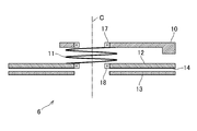
- FIG. 5 is a schematic cross-sectional view of the structure of the main part of the power generation mechanism 6 according to this embodiment.
- the rotary weight 10 is supported by a bearing 17 so as to be freely rotatable with respect to an axis C as a center of rotation
- the electret electrode 12 is also supported by a hollow shaft 18 so as to be freely rotatable with respect to the axis C.
- the rotary weight 10 and the electret electrode 12 are elastically supported by the spiral spring 11 so that the rotary motion around the axis C is mutually supported.
- An electret film 14 is formed on the surface of the electret electrode 12 facing the counter electrode 13, and the counter electrode 13 is fixed to a generator case 16 (not shown).
- the spiral spring 11 is attached to the rotary weight 10 and the electret electrode 12 and cannot be attached to a fixing member such as the generator case 16, so that it can freely rotate as a whole, and it can be wound up or stretched out.
- the moment of inertia I e moment of inertia I w and the electret electrode 12 of the rotary weight 10 is determined so that I w> I e.
- the frequency of the rotational vibration detected by the rotary weight 10 by the user's movement such as swinging the arm is about 3 to 5 Hz.
- the result of the experiment shows that the frequency is 30 to 40 Hz or more.
- the electret electrode 12 can be vibrated at a period higher than that of the rotary weight 10 by setting I w > I e , thereby generating power more efficiently. be able to.
- the rotary weight 10 is the first rotating member.
- the electret electrode 12 corresponds to the second rotating member
- the spiral spring 11 corresponds to the elastic member
- the counter electrode 13 corresponds to the fixing member
- the electret film 14 corresponds to the electret electrode 12, that is, the first member. And thus it provided on the rotating member.
- FIG. 6 is a perspective view according to a first modification of the power generation mechanism 6.
- This modification is different from the example shown in FIG. 4 in that a second rotary weight 19 is attached to a part of the outer periphery of the electret electrode 12. Since the electret electrode 12 is provided with the second rotary weight 19, the position of the center of gravity is deviated from the rotation axis C. Furthermore, this as in the previous example is also in the modification, different to the value of the moment of inertia I e moment of inertia I w and the electret electrode 12 of the rotary weight 10 to each other (in this modification, I w> I e) . By doing so, the system of the power generation mechanism 6 becomes a coupled vibration system and has two natural angular frequencies. Therefore, kinetic energy over a wider range of frequencies with respect to various vibrations applied from the outside. Can be recovered, and the power generation efficiency is improved.
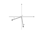
- FIG. 7 is a diagram showing the directions of W and E when the axis C is oriented in the horizontal direction.
- the vertical axis indicates the vertical direction
- the horizontal axis indicates the horizontal direction.
- W and E are stabilized in a direction in which the direction of the combined center of gravity with respect to the axis C is vertically downward.
- torque is generated clockwise on the rotary weight 10 so that W is vertically downward
- counterclockwise torque is generated on the electret electrode 12 so that E is vertically downward. To do.
- the spiral spring 11 Since these torques act to slightly wind or unwind the spiral spring 11, the spiral spring 11 is slightly wound or unwound in the free state (that is, the angle formed by W and E in the figure is smaller than ⁇ ).
- the angle formed by W and E in the figure is smaller than ⁇ .
- the configuration of the present modification can be expected to have a first effect that sensitivity to external vibration is increased.
- the difference in the moment of inertia value between the rotary weight 10 and the electret electrode 12 is mainly due to the mass difference, here, as shown in the figure, W is generally close to the vertical downward direction, and E is generally horizontal. Closer and stable. Therefore, the center of gravity of the rotary weight 10 is easy to move in the horizontal direction, and the center of gravity of the electret electrode 12 is easy to move in the vertical direction. Therefore, when the horizontal vibration is applied to the power generation mechanism 6, the vibration is rotated. When the weight 10 is given a vertical vibration, the electret electrode 12 absorbs the vibration. Therefore, the configuration of the present modification can be expected to produce a second effect that power can be generated regardless of the direction of vibration applied to the power generation mechanism 6.
- FIG. 8 is a schematic cross-sectional view of the structure of the main part of the power generation mechanism 6 according to this modification.
- the rotary weight 10 and the electret electrode 12 are supported so as to be freely rotatable with respect to the axis C, and the rotary motion around the axis C is elastically supported by the spiral spring 11.
- a second rotary weight 19 is attached to the outer periphery of the electret electrode 12.
- fixation to the electret electrode 12 of the 2nd rotary weight 19 is not limited to the aspect fixed to the upper surface of the electret electrode 12, as shown so far.
- the second rotary weight 19 may be fixed to the outer peripheral surface of the electret electrode 12 or may be separately fixed to a hollow shaft 18 (see FIG. 2) to which the electret electrode 12 is fixed.
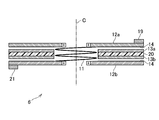
- FIG. 9 is a schematic cross-sectional view of the structure of the main part according to the second modification of the power generation mechanism 6.
- two electret electrodes are used instead of using a rotating weight.
- first electret electrode 12a and the second electret electrode 12b are supported so as to be freely rotatable with respect to the axis C, and the electret films 14 are provided on the surfaces facing each other.
- An insulating fixed substrate 20 is disposed between the first electret electrode 12a and the second electret electrode 12b, and the first counter electrode 13a and the first electret electrode 12a are respectively disposed on both surfaces thereof,
- a second counter electrode 13b is provided so as to face the second electret electrode 12b.
- a second rotating weight 19 is provided on the outer periphery of the first electret electrode 12a, and a third rotating weight 21 is provided on the outer periphery of the second electret electrode 12b.
- the first electret electrode 12 a and the second electret electrode 12 b are elastically supported by the spiral spring 11 to rotate around the axis C.
- the values of the moment of inertia I e1 of the first electret electrode 12a and the values of the second electret electrode I e2 are different.
- the orientation of the center of gravity of the first electret electrode 12a with respect to the axis C in plan view is E1
- the orientation of the center of gravity of the second electret electrode 12a is E2
- the angle formed by E1 and E2 is ⁇ , 0 ° ⁇ ⁇ 180 ° is preferable, and 45 ° ⁇ ⁇ 135 ° is more preferable.
- ⁇ 90 °.
- the first rotating member may be either the first electret electrode 12a or the second electret electrode 12b.
- the two rotating members are either one of them.
- the spiral spring 11 corresponds to an elastic member
- the first counter electrode 13a or the second counter electrode 13b corresponds to a fixed member.
- FIG. 10 is a schematic cross-sectional view of the structure of the main part according to the third modification of the power generation mechanism 6.
- this modification two electret electrodes are used in addition to the rotating weight.
- the electret film 14 is provided on the surface on the side where the first electret electrode 12a and the second electret electrode 12b face each other. Further, an insulating fixed substrate 20 is disposed between the first electret electrode 12a and the second electret electrode 12b, and the first counter electrode 13a and the first counter electrode 13a are respectively opposed to the first electret electrode 12a on both sides thereof.
- the second counter electrode 13b is provided so as to face the second electret electrode 12b.
- a second rotating weight 19 is provided on the outer periphery of the first electret electrode 12a, and a third rotating weight 21 is provided on the outer periphery of the second electret electrode 12b.
- the rotary weight 10 and the first electret electrode 12a are rotated around the axis C by the first spiral spring 11a, and the first electret electrode 12a and the second electret electrode 12b are rotated around the axis C by the second spiral spring 11b.
- the rotational movements of each other are supported elastically.
- the three members of the rotary weight 10, the first electret electrode 12a, and the second electret electrode 12b can freely rotate and are elastically supported, respectively, so that a coupled vibration system with three degrees of freedom is obtained. Is configured. Therefore, in this modification, the system has three natural angular frequencies, and power generation is possible for vibration inputs having a wider frequency range.
- the values of the inertia moment I W of the rotary weight 10, the inertia moment I e1 of the first electret electrode 12a, and the second electret electrode I e2 are different from each other.
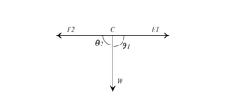
- the member having the largest moment of inertia is preferably the rotary weight 10, and as shown in FIG.
- the orientation of the center of gravity of the rotary weight 10 with respect to the axis C in plan view is W
- the center of gravity of the first electret electrode 12a is
- the direction is E1
- the direction of the center of gravity of the second electret electrode 12b is E2
- the angle between W and E1 is ⁇ 1
- the angle between W and E2 is ⁇ 2, 0 ° ⁇ 1 ⁇ 180 °, 0 °
- the rotary weight 10 corresponds to the first rotating member
- the second rotating member includes the first electret electrode 12a and the second electret.
- the first spiral spring 11a and the second spiral spring 11b correspond to elastic members
- the first counter electrode 13a and the second counter electrode 13b correspond to fixing members, respectively, and there are also a plurality (two) of them. It becomes.
- the plurality of second rotating members, that is, the first electret electrode 12a and the second electret electrode 12b are elastically connected to each other with respect to the rotational motion thereof by an elastic member (second spiral spring 11b).
- the freely rotating members may be elastically supported by the spiral springs around the axis C in order to constitute a so-called coupled vibration system as a whole.
- the number of degrees of freedom of the system increases, the number of natural angular frequencies increases, so a response to a wider range of frequencies is possible.
- FIG. 12 is a schematic cross-sectional view of the power generation mechanism 26 according to the second embodiment of the present invention. Note that the operating principle of the power generation mechanism 26 of the second embodiment described below is the same as that described in the first embodiment, and a detailed description thereof will be omitted.
- the power generation mechanism 26 includes an electret electrode 22, a counter electrode 23, and a fixed wheel 50, and accommodates them in the generator case 16.
- the electret film 24 is formed on both surfaces of the electret electrode 22, and the counter electrode 23 is fixed to the generator case 16 so as to face each electret film 24.
- the fixed wheel 50 includes a gear portion 51 that meshes with the speed increaser 30 and a rotation shaft 52 that is pivotally supported by the generator case 16, and the rotational force of the rotary weight 10 whose center of gravity is offset from the rotation center is the speed increaser. Rotating about the rotating shaft 51 by being transmitted at a speed increased via 30.
- the speed increasing device 30 may be a speed increasing wheel train composed of a plurality of gears having different gear ratios. Further, since the speed increaser 30 is not an essential configuration, the speed increaser 30 may not be provided, and the rotary weight 10 and the fixed wheel 50 may rotate on the same axis.
- a through hole is formed in the rotation center portion of the electret electrode 22, and the rotating shaft 51 of the fixed wheel 50 is inserted into the through hole.
- the spiral spring 11 is the inner peripheral surface of the electret electrode 22 so that the inner peripheral surface 22a of the through-hole of the electret electrode 22 and the outer peripheral surface of the rotating shaft 51 of the fixed wheel 50 are elastically connected to each other with respect to the rotational movement. It is accommodated on the 22a side.
- the electret electrode 22 and the spiral spring 11 may be integrally formed using a MEMS (Micro Electro Mechanical System) technique.
- the electret electrode 22 is provided with a guide portion 22b that slides on the generator case 16 as the electret electrode 22 rotates so that the electret electrode 22 and the counter electrode 23 can maintain an appropriate distance.
- the guide portion 22b may be annular or provided in a part of the circumferential direction. Further, the guide portion 22b may be configured to be fixed to the generator case 16 side instead of the electret electrode 22 side and slide on the rotating electret electrode 22.
- the guide portion 22 b is provided on the radially inner side of the electret electrode 22, but is not limited thereto, and may be provided on the radially outer side, for example, the outer peripheral edge. It may be provided both inside and outside the direction.
- the material of the guide portion 22b is preferably a material with low friction and excellent slidability.
- a fluororesin such as polytetrafluoroethylene (PTFE), an oil-containing sintered metal, or the like may be used.
- a film made of these materials may be provided on the sliding surface.
- the outward expansion of the spiral spring 11 in the radial direction is restricted by the inner peripheral surface 22a of the through hole of the electret electrode 12. Therefore, in addition to the effects described in the first embodiment, it is possible to expect an effect of suppressing breakage of the power generation mechanism 26 caused by the radial extension of the spiral spring 11. In addition, since the spiral spring 11 is accommodated on the inner peripheral surface 22a side of the electret electrode 12, the thickness of the power generation mechanism 26 in the direction of the rotation shaft 51 can be reduced.
- the position in the thickness direction is likely to change, but the gap with the electret electrode 22 is kept constant by the guide portion 22b.
- the rotary weight 10 is the first rotating member
- the electret electrode 22 is the second rotating member
- the spiral spring 11 is the elastic member
- the counter electrode 23 Corresponds to the fixing member, and the inner peripheral surface 22a of the through hole corresponds to the restricting portion.
- FIG. 13 is a perspective view of an essential part of the power generation mechanism 36 according to the third embodiment of the present invention.
- the rotating weight, the electret electrode, and the counter electrode are not shown for the sake of convenience for showing the characteristic part of the third embodiment.
- the power generation mechanism 36 includes a fixed wheel 150 and an electret electrode shaft 70 that rotates integrally with the electret electrode.
- the electret electrode shaft 70 is rotatably supported by a generator case (not shown).
- the fixed wheel 150, electret electrode, and counter electrode are arranged in the order of the fixed wheel 150, electret electrode, and counter electrode in the axial direction of the electret electrode shaft 70.
- the fixed wheel 150 is supported by being freely rotatable, and rotates when a rotational force is transmitted from a rotating weight whose center of gravity is deviated from the center of rotation. Further, a through hole is formed in the center of rotation of the fixed wheel 150, and the electret electrode shaft 70 is inserted through the through hole.
- the fixed wheel 150 and the electret electrode shaft 70 are elastically connected to each other with respect to the rotational movement by the spiral spring 11.
- the electret electrode shaft 70 and the spiral spring 11 may be integrally formed using a MEMS (Micro Electro Mechanical System) technique.
- an annular wall 60 is formed on the surface of the fixed wheel 150 (the lower surface in the present embodiment) and outside the spiral spring 11 in the radial direction.
- the wall 60 restricts the spiral spring 11 from spreading outward in the radial direction. Therefore, in addition to the effects described in the first embodiment, it is possible to expect an effect of suppressing breakage of the power generation mechanism 36 caused by the radial extension of the spiral spring 11.
- the wall 60 is formed in an annular shape over the entire circumference in the circumferential direction.
- the wall 60 is not limited to this configuration.
- the wall may be provided only on a part of the wall.
- the wall 60 may also serve as the guide portion 22b described in the second embodiment.
- the wall 60 may be configured to slide on the electret electrode 22 so that the electret electrode and the counter electrode can maintain an appropriate distance.
- the rotating weight (not shown) is the first rotating member
- the electret electrode (not shown) is the second rotating member
- the counter electrode (not shown).
- the wall 60 corresponds to the restricting portion.
Landscapes
- Engineering & Computer Science (AREA)
- Power Engineering (AREA)
- Physics & Mathematics (AREA)
- General Physics & Mathematics (AREA)
- General Electrical Machinery Utilizing Piezoelectricity, Electrostriction Or Magnetostriction (AREA)
- Electric Clocks (AREA)
- Electromechanical Clocks (AREA)
Abstract
Description
Claims (10)
- 自由回転可能に支持され、重心が回転中心から偏った少なくとも1つの第1の回転部材と、
自由回転可能に支持された少なくとも1つの第2の回転部材と、
前記第1の回転部材と前記第2の回転部材をその回転運動に関し互いに弾性的に接続する弾性部材と、
前記第2の回転部材と対向して設けられる固定部材と、を有し、前記第2の回転部材と前記固定部材のいずれかの表面にエレクトレット膜が設けられた発電機構を備えた電子機器。 - 前記第1の回転部材の慣性モーメントの値と前記第2の回転部材の慣性モーメントの値は互いに異なる請求項1に記載の電子機器。
- 前記第1の回転部材の慣性モーメントの値は前記第2の回転部材の慣性モーメントの値より大きい請求項2に記載の電子機器。
- 前記弾性部材の弛緩状態において、前記第1の回転部材の回転中心からみた重心方向と、前記第2の回転部材の回転中心からみた重心方向とがなす角θは、0°<θ<180°である請求項1~3のいずれかに記載の電子機器。
- 前記第2の回転部材の表面に前記エレクトレット膜が設けられた請求項1~4のいずれかに記載の電子機器。
- 前記第2の回転部材は、重心が回転中心から偏っている請求項1~5のいずれかに記載の電子機器。
- 前記第1の回転部材の表面にエレクトレット膜が設けられ、
前記第1の回転部材と対向して設けられる追加の固定部材が設けられる請求項1~6のいずれかに記載の電子機器。 - 前記第2の回転部材、前記固定部材及び前記弾性部材は複数設けられ、
前記複数の第2の回転部材は、前記弾性部材によりその回転運動に関し互いに弾性的に接続される請求項1~7のいずれかに記載の電子機器。 - 前記弾性部材の径方向外側への広がりを規制する規制部を有する請求項1~8のいずれかに記載の電子機器。
- 前記第2の回転部材の回転中心部には貫通孔が設けられ、
前記弾性部材は前記貫通孔の内周面側に収容される請求項1~8のいずれかに記載の電子機器。
Priority Applications (4)
| Application Number | Priority Date | Filing Date | Title |
|---|---|---|---|
| CN201580017557.9A CN106134065B (zh) | 2014-03-31 | 2015-03-26 | 电子设备 |
| JP2016511594A JP6456360B2 (ja) | 2014-03-31 | 2015-03-26 | 電子機器 |
| EP15774072.1A EP3128666B1 (en) | 2014-03-31 | 2015-03-26 | Electronic device |
| US15/300,780 US10361642B2 (en) | 2014-03-31 | 2015-03-26 | Electronic device |
Applications Claiming Priority (2)
| Application Number | Priority Date | Filing Date | Title |
|---|---|---|---|
| JP2014-073555 | 2014-03-31 | ||
| JP2014073555 | 2014-03-31 |
Publications (1)
| Publication Number | Publication Date |
|---|---|
| WO2015151996A1 true WO2015151996A1 (ja) | 2015-10-08 |
Family
ID=54240322
Family Applications (1)
| Application Number | Title | Priority Date | Filing Date |
|---|---|---|---|
| PCT/JP2015/059376 Ceased WO2015151996A1 (ja) | 2014-03-31 | 2015-03-26 | 電子機器 |
Country Status (5)
| Country | Link |
|---|---|
| US (1) | US10361642B2 (ja) |
| EP (1) | EP3128666B1 (ja) |
| JP (1) | JP6456360B2 (ja) |
| CN (1) | CN106134065B (ja) |
| WO (1) | WO2015151996A1 (ja) |
Cited By (4)
| Publication number | Priority date | Publication date | Assignee | Title |
|---|---|---|---|---|
| WO2016027748A1 (ja) * | 2014-08-22 | 2016-02-25 | シチズンホールディングス株式会社 | 静電誘導型発電器付き電子時計 |
| CN105932899A (zh) * | 2016-06-07 | 2016-09-07 | 清华大学 | 无基底电极驻极体静电发电机和制造该驻极体的方法 |
| JP2018526960A (ja) * | 2015-09-04 | 2018-09-13 | コーニンクレッカ フィリップス エヌ ヴェKoninklijke Philips N.V. | 電力生成デバイス及び電力生成方法 |
| JP2020102960A (ja) * | 2018-12-21 | 2020-07-02 | シチズン時計株式会社 | 発電システムおよび携帯型時計 |
Families Citing this family (6)
| Publication number | Priority date | Publication date | Assignee | Title |
|---|---|---|---|---|
| JP2016178821A (ja) * | 2015-03-20 | 2016-10-06 | 株式会社東芝 | 振動発電機 |
| US10734922B2 (en) * | 2017-04-05 | 2020-08-04 | Tri-Force Management Corporation | Power generating element and power generating device |
| CN108335658B (zh) | 2018-03-15 | 2021-08-06 | 京东方科技集团股份有限公司 | 显示面板和显示测试装置 |
| US11681260B2 (en) * | 2018-09-10 | 2023-06-20 | Citizen Watch Co., Ltd. | Electronic watch |
| US11650548B2 (en) * | 2019-03-13 | 2023-05-16 | Citizen Watch Co., Ltd. | Timepiece |
| USD912547S1 (en) * | 2019-03-20 | 2021-03-09 | Citizen Watch Co., Ltd. | Watch |
Citations (6)
| Publication number | Priority date | Publication date | Assignee | Title |
|---|---|---|---|---|
| JP2010041813A (ja) * | 2008-08-05 | 2010-02-18 | Sanyo Electric Co Ltd | 発電装置 |
| WO2011052106A1 (ja) * | 2009-10-29 | 2011-05-05 | パナソニック株式会社 | 発電装置 |
| JP2013059149A (ja) * | 2011-09-07 | 2013-03-28 | Seiko Instruments Inc | 発電装置、携帯型電気機器および携帯型時計 |
| JP2013135544A (ja) * | 2011-12-27 | 2013-07-08 | Citizen Holdings Co Ltd | 発電装置およびそれを備えた発電機器 |
| US20130241346A1 (en) * | 2010-11-29 | 2013-09-19 | Commissariatà L'Énergie Atomique Et Aux Énergies Alternatives | Device for converting mechanical energy into electrical energy |
| JP2013219897A (ja) * | 2012-04-06 | 2013-10-24 | Seiko Instruments Inc | 発電装置、携帯型電気機器および携帯型時計 |
Family Cites Families (11)
| Publication number | Priority date | Publication date | Assignee | Title |
|---|---|---|---|---|
| JPH1123737A (ja) | 1997-07-02 | 1999-01-29 | Citizen Watch Co Ltd | 発電装置付電子時計 |
| JP2001258227A (ja) * | 2000-01-06 | 2001-09-21 | Seiko Epson Corp | 発電装置、それを有する計時装置および電子機器、発電装置のコギングトルク調整方法 |
| JP2002296365A (ja) | 2001-03-29 | 2002-10-09 | Seiko Epson Corp | 電子機器、電子制御式機械時計、電子機器の制御方法 |
| CN1698019A (zh) | 2003-02-21 | 2005-11-16 | 精工爱普生株式会社 | 驱动装置、计时装置和计时装置的控制方法 |
| US20040233794A1 (en) | 2003-02-21 | 2004-11-25 | Seiko Epson Corporation | Timepiece driving apparatus and time calculating apparatus |
| CN100561850C (zh) | 2004-02-26 | 2009-11-18 | 精工爱普生株式会社 | 驱动控制装置、电子设备及其驱动控制方法 |
| JP2012073224A (ja) | 2010-09-03 | 2012-04-12 | Seiko Instruments Inc | 電子機器、電子機器の制御方法及び電子機器の制御プログラム |
| JPWO2015029697A1 (ja) * | 2013-08-27 | 2017-03-02 | 旭硝子株式会社 | 発電装置、時計用ムーブメントおよび時計 |
| CN103529686A (zh) | 2013-10-23 | 2014-01-22 | 沈娟燕 | 二级共振式噪声钟 |
| JP6494597B2 (ja) * | 2014-03-26 | 2019-04-03 | シチズン時計株式会社 | 静電誘導型発電器 |
| JP6562927B2 (ja) * | 2014-08-22 | 2019-08-21 | シチズン時計株式会社 | 静電誘導型発電器付き電子時計 |
-
2015
- 2015-03-26 EP EP15774072.1A patent/EP3128666B1/en active Active
- 2015-03-26 JP JP2016511594A patent/JP6456360B2/ja not_active Expired - Fee Related
- 2015-03-26 US US15/300,780 patent/US10361642B2/en not_active Expired - Fee Related
- 2015-03-26 CN CN201580017557.9A patent/CN106134065B/zh not_active Expired - Fee Related
- 2015-03-26 WO PCT/JP2015/059376 patent/WO2015151996A1/ja not_active Ceased
Patent Citations (6)
| Publication number | Priority date | Publication date | Assignee | Title |
|---|---|---|---|---|
| JP2010041813A (ja) * | 2008-08-05 | 2010-02-18 | Sanyo Electric Co Ltd | 発電装置 |
| WO2011052106A1 (ja) * | 2009-10-29 | 2011-05-05 | パナソニック株式会社 | 発電装置 |
| US20130241346A1 (en) * | 2010-11-29 | 2013-09-19 | Commissariatà L'Énergie Atomique Et Aux Énergies Alternatives | Device for converting mechanical energy into electrical energy |
| JP2013059149A (ja) * | 2011-09-07 | 2013-03-28 | Seiko Instruments Inc | 発電装置、携帯型電気機器および携帯型時計 |
| JP2013135544A (ja) * | 2011-12-27 | 2013-07-08 | Citizen Holdings Co Ltd | 発電装置およびそれを備えた発電機器 |
| JP2013219897A (ja) * | 2012-04-06 | 2013-10-24 | Seiko Instruments Inc | 発電装置、携帯型電気機器および携帯型時計 |
Cited By (6)
| Publication number | Priority date | Publication date | Assignee | Title |
|---|---|---|---|---|
| WO2016027748A1 (ja) * | 2014-08-22 | 2016-02-25 | シチズンホールディングス株式会社 | 静電誘導型発電器付き電子時計 |
| JPWO2016027748A1 (ja) * | 2014-08-22 | 2017-06-01 | シチズン時計株式会社 | 静電誘導型発電器付き電子時計 |
| US10222761B2 (en) | 2014-08-22 | 2019-03-05 | Citizen Watch Co., Ltd. | Electronic timepiece with electrostatic induction generator |
| JP2018526960A (ja) * | 2015-09-04 | 2018-09-13 | コーニンクレッカ フィリップス エヌ ヴェKoninklijke Philips N.V. | 電力生成デバイス及び電力生成方法 |
| CN105932899A (zh) * | 2016-06-07 | 2016-09-07 | 清华大学 | 无基底电极驻极体静电发电机和制造该驻极体的方法 |
| JP2020102960A (ja) * | 2018-12-21 | 2020-07-02 | シチズン時計株式会社 | 発電システムおよび携帯型時計 |
Also Published As
| Publication number | Publication date |
|---|---|
| US10361642B2 (en) | 2019-07-23 |
| CN106134065B (zh) | 2018-10-09 |
| EP3128666A4 (en) | 2017-12-27 |
| EP3128666A1 (en) | 2017-02-08 |
| US20170019035A1 (en) | 2017-01-19 |
| JP6456360B2 (ja) | 2019-01-23 |
| CN106134065A (zh) | 2016-11-16 |
| JPWO2015151996A1 (ja) | 2017-04-13 |
| EP3128666B1 (en) | 2019-05-08 |
Similar Documents
| Publication | Publication Date | Title |
|---|---|---|
| JP6456360B2 (ja) | 電子機器 | |
| JP6562927B2 (ja) | 静電誘導型発電器付き電子時計 | |
| JP5804502B2 (ja) | 発電装置、携帯型電気機器および携帯型時計 | |
| JP2011072070A (ja) | 発電装置および発電機器 | |
| JP2010286428A (ja) | 時計用発電装置および発電装置 | |
| JP2010279201A (ja) | 電池装置およびそれを備えた電子機器 | |
| JP2015186424A (ja) | 静電誘導型発電器 | |
| JP2011078214A (ja) | 発電装置および発電機器 | |
| JP7354144B2 (ja) | 携帯機器 | |
| JP5403236B2 (ja) | 発電装置 | |
| JP6558996B2 (ja) | 静電誘導型発電器 | |
| HK1233058A1 (en) | Electronic device | |
| HK1233058B (zh) | 电子设备 | |
| JP2013219897A (ja) | 発電装置、携帯型電気機器および携帯型時計 | |
| JP3232471U (ja) | 静電誘導型変換器 | |
| JP6494309B2 (ja) | 静電誘導型発電器付き電子時計 | |
| JP2015198464A (ja) | 電子時計 | |
| JP7408431B2 (ja) | 電気機械変換器 | |
| JP7069003B2 (ja) | 電気機械変換器および電子時計 | |
| US11567454B2 (en) | Electromechanical transducer and electronic timepiece | |
| JP3232472U (ja) | 時計部品 | |
| JP7292182B2 (ja) | 電気機械変換器および電子時計 | |
| JP6366396B2 (ja) | 静電誘導型発電器 | |
| JP2020129883A (ja) | 静電誘導型変換器 | |
| JP2020183915A (ja) | 基板間隔調整保持機構、基板間隔調整保持機構を備えた静電誘導変換器及び静電誘導変換器を備えた時計 |
Legal Events
| Date | Code | Title | Description |
|---|---|---|---|
| 121 | Ep: the epo has been informed by wipo that ep was designated in this application |
Ref document number: 15774072 Country of ref document: EP Kind code of ref document: A1 |
|
| ENP | Entry into the national phase |
Ref document number: 2016511594 Country of ref document: JP Kind code of ref document: A |
|
| REEP | Request for entry into the european phase |
Ref document number: 2015774072 Country of ref document: EP |
|
| WWE | Wipo information: entry into national phase |
Ref document number: 2015774072 Country of ref document: EP |
|
| NENP | Non-entry into the national phase |
Ref country code: DE |
|
| WWE | Wipo information: entry into national phase |
Ref document number: 15300780 Country of ref document: US |