WO2015152113A1 - 黒鉛系負極活物質材料、負極及びリチウムイオン二次電池 - Google Patents
黒鉛系負極活物質材料、負極及びリチウムイオン二次電池 Download PDFInfo
- Publication number
- WO2015152113A1 WO2015152113A1 PCT/JP2015/059840 JP2015059840W WO2015152113A1 WO 2015152113 A1 WO2015152113 A1 WO 2015152113A1 JP 2015059840 W JP2015059840 W JP 2015059840W WO 2015152113 A1 WO2015152113 A1 WO 2015152113A1
- Authority
- WO
- WIPO (PCT)
- Prior art keywords
- graphite
- graphite particles
- negative electrode
- active material
- electrode active
- Prior art date
- Legal status (The legal status is an assumption and is not a legal conclusion. Google has not performed a legal analysis and makes no representation as to the accuracy of the status listed.)
- Ceased
Links
Images
Classifications
-
- H—ELECTRICITY
- H01—ELECTRIC ELEMENTS
- H01M—PROCESSES OR MEANS, e.g. BATTERIES, FOR THE DIRECT CONVERSION OF CHEMICAL ENERGY INTO ELECTRICAL ENERGY
- H01M4/00—Electrodes
- H01M4/02—Electrodes composed of, or comprising, active material
- H01M4/36—Selection of substances as active materials, active masses, active liquids
- H01M4/58—Selection of substances as active materials, active masses, active liquids of inorganic compounds other than oxides or hydroxides, e.g. sulfides, selenides, tellurides, halogenides or LiCoFy; of polyanionic structures, e.g. phosphates, silicates or borates
- H01M4/583—Carbonaceous material, e.g. graphite-intercalation compounds or CFx
- H01M4/587—Carbonaceous material, e.g. graphite-intercalation compounds or CFx for inserting or intercalating light metals
-
- C—CHEMISTRY; METALLURGY
- C01—INORGANIC CHEMISTRY
- C01B—NON-METALLIC ELEMENTS; COMPOUNDS THEREOF; METALLOIDS OR COMPOUNDS THEREOF NOT COVERED BY SUBCLASS C01C
- C01B32/00—Carbon; Compounds thereof
- C01B32/20—Graphite
-
- H—ELECTRICITY
- H01—ELECTRIC ELEMENTS
- H01M—PROCESSES OR MEANS, e.g. BATTERIES, FOR THE DIRECT CONVERSION OF CHEMICAL ENERGY INTO ELECTRICAL ENERGY
- H01M4/00—Electrodes
- H01M4/02—Electrodes composed of, or comprising, active material
- H01M4/36—Selection of substances as active materials, active masses, active liquids
- H01M4/362—Composites
- H01M4/364—Composites as mixtures
-
- C—CHEMISTRY; METALLURGY
- C01—INORGANIC CHEMISTRY
- C01P—INDEXING SCHEME RELATING TO STRUCTURAL AND PHYSICAL ASPECTS OF SOLID INORGANIC COMPOUNDS
- C01P2004/00—Particle morphology
- C01P2004/30—Particle morphology extending in three dimensions
- C01P2004/32—Spheres
-
- C—CHEMISTRY; METALLURGY
- C01—INORGANIC CHEMISTRY
- C01P—INDEXING SCHEME RELATING TO STRUCTURAL AND PHYSICAL ASPECTS OF SOLID INORGANIC COMPOUNDS
- C01P2004/00—Particle morphology
- C01P2004/51—Particles with a specific particle size distribution
- C01P2004/53—Particles with a specific particle size distribution bimodal size distribution
-
- C—CHEMISTRY; METALLURGY
- C01—INORGANIC CHEMISTRY
- C01P—INDEXING SCHEME RELATING TO STRUCTURAL AND PHYSICAL ASPECTS OF SOLID INORGANIC COMPOUNDS
- C01P2006/00—Physical properties of inorganic compounds
- C01P2006/11—Powder tap density
-
- C—CHEMISTRY; METALLURGY
- C01—INORGANIC CHEMISTRY
- C01P—INDEXING SCHEME RELATING TO STRUCTURAL AND PHYSICAL ASPECTS OF SOLID INORGANIC COMPOUNDS
- C01P2006/00—Physical properties of inorganic compounds
- C01P2006/40—Electric properties
-
- H—ELECTRICITY
- H01—ELECTRIC ELEMENTS
- H01M—PROCESSES OR MEANS, e.g. BATTERIES, FOR THE DIRECT CONVERSION OF CHEMICAL ENERGY INTO ELECTRICAL ENERGY
- H01M10/00—Secondary cells; Manufacture thereof
- H01M10/05—Accumulators with non-aqueous electrolyte
- H01M10/052—Li-accumulators
- H01M10/0525—Rocking-chair batteries, i.e. batteries with lithium insertion or intercalation in both electrodes; Lithium-ion batteries
-
- H—ELECTRICITY
- H01—ELECTRIC ELEMENTS
- H01M—PROCESSES OR MEANS, e.g. BATTERIES, FOR THE DIRECT CONVERSION OF CHEMICAL ENERGY INTO ELECTRICAL ENERGY
- H01M4/00—Electrodes
- H01M4/02—Electrodes composed of, or comprising, active material
- H01M2004/021—Physical characteristics, e.g. porosity, surface area
-
- H—ELECTRICITY
- H01—ELECTRIC ELEMENTS
- H01M—PROCESSES OR MEANS, e.g. BATTERIES, FOR THE DIRECT CONVERSION OF CHEMICAL ENERGY INTO ELECTRICAL ENERGY
- H01M4/00—Electrodes
- H01M4/02—Electrodes composed of, or comprising, active material
- H01M2004/026—Electrodes composed of, or comprising, active material characterised by the polarity
- H01M2004/027—Negative electrodes
-
- Y—GENERAL TAGGING OF NEW TECHNOLOGICAL DEVELOPMENTS; GENERAL TAGGING OF CROSS-SECTIONAL TECHNOLOGIES SPANNING OVER SEVERAL SECTIONS OF THE IPC; TECHNICAL SUBJECTS COVERED BY FORMER USPC CROSS-REFERENCE ART COLLECTIONS [XRACs] AND DIGESTS
- Y02—TECHNOLOGIES OR APPLICATIONS FOR MITIGATION OR ADAPTATION AGAINST CLIMATE CHANGE
- Y02E—REDUCTION OF GREENHOUSE GAS [GHG] EMISSIONS, RELATED TO ENERGY GENERATION, TRANSMISSION OR DISTRIBUTION
- Y02E60/00—Enabling technologies; Technologies with a potential or indirect contribution to GHG emissions mitigation
- Y02E60/10—Energy storage using batteries
Definitions
- the present invention relates to a graphite-based negative electrode active material, a negative electrode, and a lithium ion secondary battery.
- lithium ion secondary batteries Since lithium ion secondary batteries have high energy density and excellent charge / discharge cycle characteristics, they are widely used as power sources for small mobile devices such as mobile phones and laptop computers. In recent years, demand for large-capacity batteries that require a large capacity and a long life, such as electric vehicles, hybrid electric vehicles, and the power storage field, has increased due to increased consideration for environmental issues and energy conservation.
- a lithium ion secondary battery includes a negative electrode including a carbon material capable of occluding and releasing lithium ions as a negative electrode active material, a positive electrode including a lithium composite oxide capable of occluding and releasing lithium ions as a positive electrode active material, and a negative electrode and a positive electrode. And a non-aqueous electrolyte in which a lithium salt is dissolved in a non-aqueous solvent.
- amorphous carbon or graphite is used, and graphite is generally used in applications that require a high energy density.
- the surface is coated with scaly graphite particles and amorphous carbon as a negative electrode active material, and It consists of a carbon material containing at least two types of non-flaky graphite materials, the negative electrode packing density is in the range of 1.3 to 1.8 g / cc, and the negative electrode specific surface area is in the range of 2.1 to 4.1 cm 2 / g.
- the negative electrode packing density is in the range of 1.3 to 1.8 g / cc
- the negative electrode specific surface area is in the range of 2.1 to 4.1 cm 2 / g.
- Patent Document 2 scaly graphite, spheroidal graphite, and massive graphite are used as a negative electrode active material in order to obtain a nonaqueous electrolyte battery having high capacity and high cycle characteristics and high volume energy density even in large current discharge.
- a negative electrode active material mixture comprising at least one carbon material of fibrous graphite, non-graphitizable carbon, or carbon black.
- the negative electrode active material mixture contains 1% by weight or more of the one or more carbon materials. It is disclosed to use those containing in the range of 50% by weight or less.
- Patent Document 3 discloses a tap density for the purpose of improving or maintaining the discharge rate characteristics, the low temperature discharge characteristics, and the heat resistance, while at the same time greatly improving the charge / discharge cycle characteristics of a high energy density lithium secondary battery. It is disclosed that an active material composed of a mixture of artificial graphite particles of 1 g / cm 3 or more and spherical graphite particles having a high degree of circularity is used. Further, it is described that the ratio of the spherical graphite particles in the entire active material is preferably 5 to 45% by mass.
- Patent Document 4 scaly natural graphite and a binder pitch are mixed, molded, calcined graphitized and pulverized, and the tap density is 0.4 to 0.9 g / cm 3 and D 90 / D 10 is 3.
- Graphite powder A having 5 to 7.0, D 50 of 10 to 20 ⁇ m and spherical natural graphite are coated with pitch and calcined graphitized, and tap density is 0.9 to 1.4 g / cm 3 , D 90 / D 10 is 2.0 to 3.5, D 50 is 10 to 20 ⁇ m, a mixed powder of graphite powder B having a circularity of 0.91 or more, and the weight mixing ratio of graphite powder A is 20 to 80%,
- a negative electrode active material for a lithium ion secondary battery in which the weight mixing ratio of the graphite powder B is 20 to 80% is disclosed.
- the object is to provide a negative electrode active material for a lithium ion secondary battery having high electrode density, excellent electrolyte
- lithium ion secondary batteries using a graphite-based negative electrode active material are required to further improve cycle characteristics.
- An object of the present invention is to provide a graphite-based negative electrode active material for a lithium ion secondary battery having excellent cycle characteristics, a negative electrode using the same, and a lithium ion secondary battery having improved cycle characteristics.
- a graphite-based negative electrode active material comprising first spheroidized graphite particles and second graphite particles having a lower circularity than the first graphite particles,
- the content of the second graphite particles with respect to the total of the first graphite particles and the second graphite particles is in the range of 1 to 30% by mass;
- the ratio D 50 / D 5 of the median particle diameter (D 50 ) to the 5% cumulative particle diameter (D 5 ) in the cumulative distribution of the first graphite particles is 5% cumulative in the cumulative distribution of the second graphite particles.
- the graphite-based negative electrode active in which the saturated tap density of the mixed particles of the first graphite particles and the second graphite particles is larger than both the saturated tap density of the first graphite particles and the saturated tap density of the second graphite particles.
- a material material is provided.
- a negative electrode for a lithium ion secondary battery comprising the above graphite-based negative electrode active material.
- a lithium ion secondary battery comprising a positive electrode including a positive electrode active material capable of occluding and releasing lithium ions, the negative electrode, and a non-aqueous electrolyte.
- a graphite-based negative electrode active material for a lithium ion secondary battery having excellent cycle characteristics, a negative electrode using the same, and a lithium ion secondary battery having improved cycle characteristics are provided. Can do.
- the graphite-based negative electrode active material according to the embodiment of the present invention includes first spherical graphite particles and second graphite particles having a lower degree of circularity than the first graphite particles, and the first graphite particles and the second graphite particles.
- the content of the second graphite particles with respect to the total of the graphite particles is in the range of 1 to 30% by mass.
- the ratio D 50 / D 5 of the median particle diameter (D 50 ) to the cumulative particle diameter (D 5 ) of 5% in the cumulative distribution of the first graphite particles is the second graphite particle Saturation tap of mixed particles of first graphite particles and second graphite particles smaller than the ratio D 50 / D 5 of the median particle diameter (D 50 ) to the cumulative particle diameter (D 5 ) of 5% in the cumulative distribution of The density is higher than both the saturated tap density of the first graphite particles and the saturated tap density of the second graphite particles.
- Lithium ion secondary battery using this negative electrode by using a graphite-based negative electrode active material material containing first and second graphite particles satisfying specific conditions for particle shape, particle size distribution and saturation tap density for the formation of the negative electrode
- the battery performance, particularly the cycle characteristics can be improved.
- the content ratio of the second graphite particles relative to the total of the first graphite particles and the second graphite particles is set in the range of 1 to 30% by mass, preferably 5% by mass or more, more preferably 10% by mass or more, Moreover, 25 mass% or less is preferable, and 20 mass% or less is more preferable. If the content of the second graphite particles is too small or too large, it becomes difficult to obtain a desired effect of improving cycle characteristics. Also, for example, when natural graphite particles are used as the first graphite particles and artificial graphite particles are used as the second graphite particles, the artificial graphite particles are generally harder than the natural graphite particles.
- Electrodes with uniform density are in contact with each other while having appropriate voids, so that the electrolyte has good penetration and retention and conductivity, contributing to improved battery characteristics such as cycle characteristics. can do. Further, as a result of the press pressure being uniformly transmitted into the electrode, an increase in electrode thickness (spring back) due to residual stress after pressing can be suppressed, and as a result, a decrease in electrode capacity can also be suppressed.
- the ratio D 50 / D 5 of the median particle diameter (D 50 ) to the cumulative particle diameter (D 5 ) of 5% in the cumulative distribution of the first graphite particles is 2nd.
- the ratio of the median particle diameter (D 50 ) to the 5% cumulative particle diameter (D 5 ) in the cumulative distribution of graphite particles is smaller than D 50 / D 5 .
- Is D 50 / D 5 of the first graphite particle D 50 / D 5 is smaller than the second graphite particles, i.e., the first graphite particles having a sharp particle size distribution, the having a relatively broad particle size distribution
- the filling rate is increased and the saturated tap density of the mixture is increased.
- Scale-like particles can be used as the second graphite particles. If the content of the second graphite particles having a low degree of circularity is too large, the spring back becomes large or the peel strength of the electrode decreases, making it difficult to cope with the volume change during the cycle. The capacity tends to decrease, and the cycle characteristics of the battery decrease. In addition, when artificial graphite is used as the second graphite particles, it is more expensive than natural graphite. Therefore, if the content of the second graphite particles is too large, the cost increases. Also from these viewpoints, the content of the second graphite particles is preferably 30% by mass or less, more preferably 25% by mass or less, and further preferably 20% by mass or less.
- the first graphite particles are spheroidized (non-flaky) graphite particles, and the average particle circularity is preferably in the range of 0.6 to 1, more preferably in the range of 0.86 to 1. The range of 0.90 to 1 is more preferable, and the range of 0.93 to 1 is particularly preferable.
- the spheronization treatment can be performed by a normal method.
- Such first graphite particles are preferably spheroidized natural graphite particles from the viewpoint of increasing the capacity while suppressing raw material costs, and generally available spheroidized natural graphite materials can be used.
- the second graphite particles are graphite particles having a lower average particle circularity than the first graphite particles, and the average particle circularity is preferably less than 0.86, more preferably 0.85 or less. More preferably, it is 0.80 or less.
- graphite particles having an average particle circularity of 0.5 or more and less than 0.86, or graphite particles having an average particle circularity of 0.6 to 0.85 can be used.
- scaly particles can be suitably used.
- the particle circularity is given by a ratio of l / L between the peripheral length l of an equivalent circle having the same area as the particle projected image and the peripheral length L of the particle projected image when the particle image is projected on a plane. .
- the average particle circularity can be measured as follows using a commercially available electron microscope. In this embodiment and the examples described later, the measurement was performed as follows using a scanning electron microscope (trade name: S-2500) manufactured by Hitachi, Ltd. First, an image with a magnification of 1000 times of graphite particles (powder) was observed with an electron microscope, and the peripheral length L of the projected image on the plane was determined. Then, the perimeter length l of the equivalent circle having the same area as the observed projected image of the particle was obtained. Ratio of the perimeter length l to the perimeter length L of the particle projection image: l / L was determined for any 50 particles, and the average value was defined as the average particle circularity. Such measurement can also be performed using a flow particle image analyzer. For example, it was confirmed that substantially the same value was obtained even when the particle circularity was measured using a powder measuring device (trade name: FPIA-1000) sold by Hosokawa Micron Corporation.
- the second graphite particles are preferably artificial graphite particles from the viewpoint that they have an appropriate degree of graphitization and hardness, are low in impurities, have low electrical resistance, and are advantageous for improving battery performance such as cycle characteristics.
- a graphite material can be used.
- graphitizable carbon such as coke (petroleum-based coke, coal-based coke, etc.) and pitch (coal-based pitch, petroleum-based pitch, coal tar pitch, etc.) is heat-treated at a high temperature of 2000 to 3000 ° C, preferably 2500 ° C or higher.
- artificial graphite graphitized The graphitized using 2 or more types of graphitizable carbon is also mentioned.
- the content of the second graphite particles relative to the total of the first graphite particles and the second graphite particles is set in the range of 1 to 30% by mass, preferably 5% by mass or more, and more preferably 10% by mass or more. Is more preferable, 25 mass% or less is preferable, and 20 mass% or less is more preferable.
- Artificial graphite is generally more expensive than natural graphite. Therefore, when artificial graphite is used as the second graphite particles, the content is preferably as low as possible within a range where a sufficient addition effect can be obtained from the viewpoint of cost.
- the ratio D 50 / D 5 of the median particle diameter (D 50 ) to the 5% cumulative particle diameter (D 5 ) in the cumulative distribution of the first graphite particles is the cumulative in the cumulative distribution of the second graphite particles.
- the ratio of the median particle diameter (D 50 ) to the 5% particle diameter (D 5 ) is preferably smaller than D 50 / D 5 .
- D 50 / D 5 of the first graphite particles is preferably 1.5 or less, and more preferably 1.36 or less.
- D 50 / D 5 of the second graphite particles is preferably larger than 1.5, and more preferably larger than 1.52.
- the particle diameter D 5 and means a particle diameter at an integrated value 5% in the particle size distribution (volume basis) by a laser diffraction scattering method
- the particle diameter D 50 is the particle size distribution by a laser diffraction scattering method (by volume) Means the particle diameter at an integrated value of 50%.
- the saturation tap density of the mixed particles of the first graphite particles and the second graphite particles is changed to the saturation of each of the first and second graphite particles. It can be higher than the tap density.
- the saturated tap density of the mixed particles of the first graphite particles and the second graphite particles is more preferably 1.1 g / cm 3 or more, and can be in the range of 1.1 to 1.30 g / cm 3 , for example. Also, it can be in the range of 1.1 to 1.25 g / cm 3 .
- the saturated tap density of the first graphite particles is preferably larger than 0.8 g / cm 3, more preferably 0.9 g / cm 3 or more, and smaller than 1.25 g / cm 3. Furthermore, 1.20 g / cm 3 or less can be used. Saturated tapping density of the second graphite particle is preferably greater than 0.8 g / cm 3, also it can be used as less than 1.10 g / cm 3, a further 1.00 g / cm 3 or less of those Can be used.
- the saturation tap density can be measured using a commercially available measuring instrument as follows. In this embodiment and the examples described later, measurement was performed as follows using a measuring instrument (trade name: Tap Denser KYT-3000) manufactured by Seishin Co., Ltd. First, approximately 40 cc (40 cm 3 ) of graphite powder was put into a 45 cc (45 cm 3 ) tapping cell. After tapping 1000 times, the tap density was calculated by the following formula.
- the average particle diameter of the negative electrode active material containing the first and second graphite particles is preferably in the range of 2 to 40 ⁇ m from the viewpoint of charge / discharge efficiency, input / output characteristics, and the like, and is preferably in the range of 5 to 30 ⁇ m. It is more preferable.
- the average particle diameter of the first graphite particles alone is preferably in the range of 10 to 20 ⁇ m
- the average particle diameter of the second graphite particles alone is preferably in the range of 5 to 30 ⁇ m.
- the average particle diameter means a particle diameter (median diameter: D 50 ) at an integrated value of 50% in a particle size distribution (volume basis) by a laser diffraction scattering method.
- the BET specific surface areas of the first and second graphite particles are in the range of 0.3 to 10 m 2 / g from the viewpoint of charge / discharge efficiency and input / output characteristics. It is preferably within the range of 0.5 to 10 m 2 / g, more preferably within the range of 0.5 to 7.0 m 2 / g.
- first graphite particles spherical particles (non-flaky particles) are used
- second graphite particles particles having a lower circularity than the first graphite particles (for example, scaly particles) are used.
- the second graphite particles can be uniformly dispersed and buried between the first graphite particles, and the first and second particles Can be filled with high density.
- the electrolyte is sufficiently infiltrated and the contacts between the particles are sufficiently formed, so that an increase in resistance during the cycle is suppressed and the capacity is unlikely to decrease.
- the first graphite particles can be coated with amorphous carbon.
- the second graphite particles may also be coated with amorphous carbon.
- the method of coating the surface of the graphite particles with amorphous carbon can be performed according to a usual method. For example, a method in which an organic substance such as tar pitch is attached to the graphite particle surface and heat-treated, or a chemical vapor deposition method (CVD method) or a sputtering method (for example, ion beam sputtering) using an organic substance such as condensed hydrocarbon such as benzene or xylene. Method), a vacuum deposition method, a plasma method, an ion plating method, or the like.
- CVD method chemical vapor deposition method
- a sputtering method for example, ion beam sputtering
- the second graphite particles may also be coated with amorphous carbon.
- amorphous carbon By covering the graphite particles with amorphous carbon, side reactions between the graphite particles and the electrolytic solution can be suppressed, the charge / discharge efficiency can be improved, the reaction capacity can be increased, and the hardness of the graphite particles can be increased. Can be high.
- the first and second graphite particles can be mixed by a known mixing method. If necessary, other active material materials may be mixed within a range that does not impair the desired effect. 90 mass% or more is preferable and, as for the total content of the 1st and 2nd graphite particle with respect to the whole negative electrode active material, 95 mass% or more is more preferable.
- the negative electrode active material can be composed of only the first and second graphite particles.
- Negative electrode As a negative electrode for a lithium ion secondary battery according to an embodiment of the present invention, for example, a negative electrode current collector provided with a negative electrode active material layer containing a graphite-based negative electrode active material and a binder according to the above-described embodiment Can be used.
- the negative electrode can be formed by a general slurry coating method.
- a negative electrode active material is prepared on a negative electrode current collector by preparing a slurry containing the negative electrode active material, a binder and a solvent, applying the slurry onto the negative electrode current collector, drying, and pressing as necessary.
- a negative electrode provided with a layer can be obtained.
- the method for applying the negative electrode slurry include a doctor blade method, a die coater method, and a dip coating method.
- a negative electrode can be obtained by forming a thin film of aluminum, nickel, or an alloy thereof as a current collector by a method such as vapor deposition or sputtering.
- the binder for the negative electrode is not particularly limited, but polyvinylidene fluoride (PVdF), vinylidene fluoride-hexafluoropropylene copolymer, vinylidene fluoride-tetrafluoroethylene copolymer, styrene-butadiene.
- NMP N-methyl-2-pyrrolidone
- water carboxymethyl cellulose, methyl cellulose, hydroxymethyl cellulose, ethyl cellulose, and polyvinyl alcohol can be used as a thickener.
- the content of the binder for the negative electrode is preferably in the range of 0.1 to 30 parts by mass with respect to 100 parts by mass of the negative electrode active material, from the viewpoints of binding force and energy density that are in a trade-off relationship.
- the range of 0.5 to 25 parts by mass is more preferable, and the range of 1 to 20 parts by mass is more preferable.
- the negative electrode current collector is not particularly limited, but copper, nickel, stainless steel, molybdenum, tungsten, tantalum and an alloy containing two or more of these are preferable from the viewpoint of electrochemical stability.
- Examples of the shape include foil, flat plate, and mesh.
- the lithium ion secondary battery by embodiment of this invention contains the said negative electrode, a positive electrode, and electrolyte.
- a slurry containing a positive electrode active material, a binder, and a solvent (and a conductive auxiliary material if necessary) is prepared, applied to the positive electrode current collector, dried, and pressurized as necessary.
- a positive electrode active material layer can be formed on the positive electrode current collector.
- lithium complex oxide which has a layered rock salt type structure or a spinel type structure, lithium iron phosphate which has an olivine type structure, etc.
- lithium composite oxide examples include lithium manganate (LiMn 2 O 4 ); lithium cobaltate (LiCoO 2 ); lithium nickelate (LiNiO 2 ); and at least part of the manganese, cobalt, and nickel portions of these lithium compounds.
- lithium composite oxides may be used individually by 1 type, and 2 or more types may be mixed and used for them.
- the specific surface area of the positive electrode active material (BET specific surface area based on measurement at 77K by the nitrogen adsorption method) is preferably in the range of 0.01 to 10 m 2 / g, and in the range of 0.1 to 3 m 2 / g. More preferred. A larger specific surface area requires more binder, which is disadvantageous in terms of electrode capacity density. If the specific surface area is too small, the ionic conductivity between the electrolytic solution and the active material may be reduced.
- the average particle diameter of the positive electrode active material is preferably in the range of 0.1 to 50 ⁇ m, more preferably in the range of 1 to 30 ⁇ m, and more preferably in the range of 5 to 25 ⁇ m, from the viewpoint of reactivity with the electrolyte, rate characteristics, and the like. A range is more preferred.
- the average particle diameter means the particle diameter (median diameter: D 50 ) at an integrated value of 50% in the particle size distribution (volume basis) by the laser diffraction scattering method.
- the binder for the positive electrode is not particularly limited, but the same binder as that for the negative electrode can be used. Among these, polyvinylidene fluoride is preferable from the viewpoint of versatility and low cost.
- the content of the binder for the positive electrode is preferably in the range of 1 to 25 parts by mass with respect to 100 parts by mass of the positive electrode active material, from the viewpoints of binding force and energy density which are in a trade-off relationship. The range of 20 parts by mass is more preferable, and the range of 2 to 10 parts by mass is more preferable.
- binders other than polyvinylidene fluoride (PVdF) vinylidene fluoride-hexafluoropropylene copolymer, vinylidene fluoride-tetrafluoroethylene copolymer, styrene-butadiene copolymer rubber, polytetrafluoroethylene, polypropylene,
- PVdF polyvinylidene fluoride
- Examples include polyethylene, polyimide, and polyamideimide.
- NMP N-methyl-2-pyrrolidone
- NMP N-methyl-2-pyrrolidone
- the positive electrode current collector is not particularly limited, but from the viewpoint of electrochemical stability, for example, aluminum, titanium, tantalum, stainless steel (SUS), other valve metals, or alloys thereof are used. Can be used. Examples of the shape include foil, flat plate, and mesh. In particular, an aluminum foil can be suitably used.
- a conductive auxiliary material may be added to the positive electrode active material layer for the purpose of reducing impedance.
- the conductive auxiliary material include carbonaceous fine particles such as graphite, carbon black, and acetylene black.
- a nonaqueous electrolytic solution in which a lithium salt is dissolved in one or two or more nonaqueous solvents can be used.
- cyclic carbonates such as ethylene carbonate (EC), propylene carbonate (PC), butylene carbonate (BC), and vinylene carbonate (VC); Dimethyl carbonate (DMC), Chain carbonates such as diethyl carbonate (DEC), ethyl methyl carbonate (EMC) and dipropyl carbonate (DPC); aliphatic carboxylic acid esters such as methyl formate, methyl acetate and ethyl propionate; ⁇ -lactones such as ⁇ -butyrolactone Chain ethers such as 1,2-ethoxyethane (DEE) and ethoxymethoxyethane (EME); and cyclic ethers such as tetrahydrofuran and 2-methyltetrahydrofur
- non-aqueous solvents include dimethyl sulfoxide, 1,3-dioxolane, dioxolane derivatives, formamide, acetamide, dimethylformamide, acetonitrile, propionitrile, nitromethane, ethyl monoglyme, phosphate triester, trimethoxymethane, sulfolane, methyl Non-protons such as sulfolane, 1,3-dimethyl-2-imidazolidinone, 3-methyl-2-oxazolidinone, propylene carbonate derivatives, tetrahydrofuran derivatives, ethyl ether, 1,3-propane sultone, anisole, N-methylpyrrolidone An organic solvent can also be used.
- lithium salt dissolved in the nonaqueous solvent is not particularly limited, for example LiPF 6, LiAsF 6, LiAlCl 4 , LiClO 4, LiBF 4, LiSbF 6, LiCF 3 SO 3, LiCF 3 CO 2, Li (CF 3 SO 2 ) 2 , LiN (CF 3 SO 2 ) 2 , and lithium bisoxalatoborate are included. These lithium salts can be used individually by 1 type or in combination of 2 or more types. Moreover, a polymer component may be included as a non-aqueous electrolyte.
- a separator can be provided between the positive electrode and the negative electrode.
- a porous film, a woven fabric, or a nonwoven fabric made of a polyolefin such as polypropylene or polyethylene, a fluororesin such as polyvinylidene fluoride, polyimide, or the like can be used.
- Battery shapes include cylindrical, square, coin type, button type, and laminate type.
- a laminate type it is preferable to use a laminate film as an exterior body that accommodates a positive electrode, a separator, a negative electrode, and an electrolyte.
- the laminate film includes a resin base material, a metal foil layer, and a heat seal layer (sealant).
- the resin base material include polyester and nylon
- examples of the metal foil layer include aluminum, an aluminum alloy, and a titanium foil.
- the material for the heat welding layer include thermoplastic polymer materials such as polyethylene, polypropylene, and polyethylene terephthalate.
- the resin base material layer and the metal foil layer are not limited to one layer, and may be two or more layers. From the viewpoint of versatility and cost, an aluminum laminate film is preferable.
- the positive electrode, the negative electrode, and the separator disposed between them are accommodated in an outer container made of a laminate film or the like, and an electrolyte is injected and sealed.
- a structure in which an electrode group in which a plurality of electrode pairs are stacked can be accommodated.
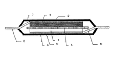
- FIG. 1 shows a cross-sectional view of an example (laminate type) lithium ion secondary battery according to an embodiment of the present invention.
- the lithium ion secondary battery according to the present embodiment includes a positive electrode current collector 3 made of a metal such as an aluminum foil, and a positive electrode active material layer 1 containing a positive electrode active material provided thereon.
- a negative electrode current collector 4 made of a metal such as copper foil and a negative electrode active material layer 2 containing a negative electrode active material provided thereon.
- the positive electrode and the negative electrode are laminated via a separator 5 made of a nonwoven fabric or a polypropylene microporous film so that the positive electrode active material layer 1 and the negative electrode active material layer 2 face each other.
- This electrode pair is accommodated in a container formed of exterior bodies 6 and 7 such as an aluminum laminate film.
- a positive electrode tab 9 is connected to the positive electrode current collector 3, and a negative electrode tab 8 is connected to the negative electrode current collector 4, and these tabs are drawn out of the container.
- An electrolytic solution is injected into the container and sealed. It can also be set as the structure where the electrode group by which the several electrode pair was laminated
- Saturated tapping density of the graphite A and graphite B is a result of measurement by the measuring method described above, each of 1.08 g / cm 3, it was 0.99 g / cm 3.
- the saturated tap density of the mixed particles of graphite A and graphite B was also measured in the same manner as shown in Table 1.
- Graphite A and graphite B were mixed at a mass ratio shown in Table 1, and this mixture (negative electrode active material) and carboxymethylcellulose 1.0 wt% aqueous solution were mixed to prepare a slurry. This was mixed with a styrene-butadiene copolymer as a binder.
- This slurry was applied to one side of a 10 ⁇ m thick copper foil, and the coating film was dried. Then, it roll-pressed so that the density of a coating film (negative electrode coating film) might be 1.5 g / cm ⁇ 3 >, and the 33 * 45 mm negative electrode sheet was obtained.
- a slurry was prepared by dispersing in methyl-2-pyrrolidone. This slurry was applied to both surfaces of an aluminum foil, and the coating film was dried. Then, it roll-pressed so that the density of a coating film (positive electrode coating film) might be 3.0 g / cm ⁇ 3 >, and the positive electrode sheet of 30x40 mm was obtained.
- the negative electrode sheet was overlapped on both sides of the positive electrode sheet so that the positive electrode coating film and the negative electrode coating film face each other through a separator made of a porous polyethylene film having a thickness of 25 ⁇ m. After the lead electrode for the positive electrode and the lead electrode for the negative electrode were provided, the laminate was wrapped with a laminate film, and an electrolyte solution was injected and sealed.
- lithium carbonate (LiPF 6 ) was dissolved to a concentration of 1.0 mol / L in a mixture of ethylene carbonate and diethyl carbonate at a volume ratio of 3: 7 was used.
- the lithium ion secondary battery produced as described above was subjected to a charge / discharge cycle test (Cycle-Rate: 1C, temperature: 45 ° C., upper limit voltage: 4.2V, lower limit voltage: 3.0V), and after 400 cycles The capacity maintenance rate was obtained. The results are shown in Table 1.
- Lithium ion secondary batteries were produced in the same manner as in Examples 1 to 3, except that only graphite A was used as the negative electrode active material.
- Lithium ion secondary batteries were produced in the same manner as in Examples 1 to 3, except that only graphite B was used as the negative electrode active material.
Landscapes
- Chemical & Material Sciences (AREA)
- Chemical Kinetics & Catalysis (AREA)
- Electrochemistry (AREA)
- General Chemical & Material Sciences (AREA)
- Inorganic Chemistry (AREA)
- Organic Chemistry (AREA)
- Composite Materials (AREA)
- Life Sciences & Earth Sciences (AREA)
- General Life Sciences & Earth Sciences (AREA)
- Geology (AREA)
- Battery Electrode And Active Subsutance (AREA)
- Secondary Cells (AREA)
- Engineering & Computer Science (AREA)
- Materials Engineering (AREA)
- Manufacturing & Machinery (AREA)
Abstract
Description
第1の黒鉛粒子と第2の黒鉛粒子の合計に対する第2の黒鉛粒子の含有率が1~30質量%の範囲にあり、
第1の黒鉛粒子の累積分布における累積5%の粒子径(D5)に対するメジアン粒子径(D50)の比D50/D5が、第2の黒鉛粒子の累積分布における累積5%の粒子径(D5)に対するメジアン粒子径(D50)の比D50/D5より小さく、
第1の黒鉛粒子と第2の黒鉛粒子との混合粒子の飽和タップ密度は、第1の黒鉛粒子の飽和タップ密度および第2の黒鉛粒子の飽和タップ密度のいずれよりも大きい、黒鉛系負極活物質材料が提供される。
第1の黒鉛粒子は、球形化された(非鱗片状)黒鉛粒子であり、その平均粒子円形度が0.6~1の範囲にあることが好ましく、0.86~1の範囲がより好ましく、0.90~1の範囲がさらに好ましく、0.93~1の範囲が特に好ましい。球形化処理は通常の方法で行うことができる。このような第1の黒鉛粒子は、原料コストを抑えながら高容量化を図る観点から、球形化された天然黒鉛粒子が好ましく、一般に入手できる球形化処理された天然黒鉛材料を用いることができる。
(式中、A:タッピングセルの質量、B:タッピングセルと黒鉛粉末の合計質量、D:充填容積)。
本発明の実施形態によるリチウムイオン二次電池用負極としては、例えば、負極集電体上に、上述の実施形態による黒鉛系負極活物質材料と結着剤を含む負極活物質層を設けたものを用いることができる。
本発明の実施形態によるリチウムイオン二次電池は、上記負極と正極と電解質を含む。
高円形度の黒鉛Aとして球形化された天然黒鉛粒子を用意し、低円形度の黒鉛Bとして鱗片状の人造黒鉛を用意した。前述の測定方法により、黒鉛Aの平均粒子円形度は0.86以上であり、鱗片状の黒鉛Bの平均粒子円形度より高いことを確認した。また、市販のレーザ回折・散乱方式粒子径分布測定装置を用いて、黒鉛AのD50/D5は1.36以下、D50は10~20μmの範囲にあり、黒鉛BのD50/D5は1.52より大きく、D50は5~30μmの範囲にあることを確認した。黒鉛Aと黒鉛Bの飽和タップ密度は、前述の測定方法により測定した結果、それぞれ1.08g/cm3、0.99g/cm3であった。黒鉛Aと黒鉛Bの混合粒子の飽和タップ密度も同様に測定し、表1に示す通りであった。
負極活物質として黒鉛Aのみを用いた以外は実施例1~3と同様にしてリチウムイオン二次電池を作製した。
負極活物質として黒鉛Bのみを用いた以外は実施例1~3と同様にしてリチウムイオン二次電池を作製した。

2 負極活物質層
3 正極集電体
4 負極集電体
5 セパレータ
6 ラミネート外装体
7 ラミネート外装体
8 負極タブ
9 正極タブ
Claims (18)
- 球形化された第1の黒鉛粒子と第1の黒鉛粒子より円形度の低い第2の黒鉛粒子を含む黒鉛系負極活物質材料であって、
第1の黒鉛粒子と第2の黒鉛粒子の合計に対する第2の黒鉛粒子の含有率が1~30質量%の範囲にあり、
第1の黒鉛粒子の累積分布における累積5%の粒子径(D5)に対するメジアン粒子径(D50)の比D50/D5が、第2の黒鉛粒子の累積分布における累積5%の粒子径(D5)に対するメジアン粒子径(D50)の比D50/D5より小さく、
第1の黒鉛粒子と第2の黒鉛粒子との混合粒子の飽和タップ密度は、第1の黒鉛粒子の飽和タップ密度および第2の黒鉛粒子の飽和タップ密度のいずれよりも大きい、黒鉛系負極活物質材料。 - 第1の黒鉛粒子のD50/D5が1.5以下である、請求項1に記載の黒鉛系負極活物質材料。
- 第1の黒鉛粒子のD50/D5が1.36以下である、請求項1に記載の黒鉛系負極活物質材料。
- 第2の黒鉛粒子のD50/D5が1.5より大きい、請求項1から3のいずれか一項に記載の黒鉛系負極活物質材料。
- 第2の黒鉛粒子のD50/D5が1.52より大きい、請求項1から3のいずれか一項に記載の黒鉛系負極活物質材料。
- 第1の黒鉛粒子と第2の黒鉛粒子との混合粒子の飽和タップ密度が1.1g/cm3以上である、請求項1から5のいずれか一項に記載の黒鉛系負極活物質材料。
- 第1の黒鉛粒子の飽和タップ密度が0.8g/cm3より大きい、請求項1から6のいずれか一項に記載の黒鉛系負極活物質材料。
- 第2の黒鉛粒子の飽和タップ密度が0.8g/cm3より大きい、請求項7に記載の黒鉛系負極活物質材料。
- 第1の黒鉛粒子と第2の黒鉛粒子の合計に対する第2の黒鉛粒子の含有率が5~30質量%の範囲にある、請求項1から8のいずれか一項に記載の黒鉛系負極活物質材料。
- 第1の黒鉛粒子と第2の黒鉛粒子の合計に対する第2の黒鉛粒子の含有率が5~20質量%の範囲にある、請求項1から8のいずれか一項に記載の黒鉛系負極活物質材料。
- 第1の黒鉛粒子のメジアン粒子径(D50)が10~20μmの範囲にあり、
第2の黒鉛粒子のメジアン粒子径(D50)が5~30μmの範囲にある、請求項1から10のいずれか一項に記載の黒鉛系負極活物質材料。 - 第1の黒鉛粒子は、その平均粒子円形度が0.6~1の範囲にある、請求項1から11のいずれか一項に記載の黒鉛系負極活物質材料。
- 第1の黒鉛粒子は、天然黒鉛粒子からなる、請求項1から12のいずれか一項に記載の黒鉛系負極活物質材料。
- 第1の黒鉛粒子は、非晶質炭素で被覆されている、請求項13に記載の黒鉛系負極活物質材料。
- 第2の黒鉛粒子は、鱗片状粒子からなる、請求項1から14のいずれか一項に記載の黒鉛系負極活物質材料。
- 第2の黒鉛粒子は、人造黒鉛粒子からなる、請求項1から15のいずれか一項に記載の黒鉛系負極活物質材料。
- 請求項1から16のいずれか一項に記載の黒鉛系負極活物質材料を含む、リチウムイオン二次電池用負極。
- リチウムイオンを吸蔵放出できる正極活物質を含む正極と、請求項17に記載の負極と、非水電解液とを含む、リチウムイオン二次電池。
Priority Applications (5)
| Application Number | Priority Date | Filing Date | Title |
|---|---|---|---|
| JP2016511859A JP6545663B2 (ja) | 2014-03-31 | 2015-03-30 | リチウムイオン二次電池用黒鉛系負極活物質材料、リチウムイオン二次電池用負極及びリチウムイオン二次電池 |
| CN201910192529.0A CN110137442B (zh) | 2014-03-31 | 2015-03-30 | 基于石墨的负电极活性材料、负电极和锂离子二次电池 |
| CN201580018155.0A CN106463727B (zh) | 2014-03-31 | 2015-03-30 | 基于石墨的负电极活性材料、负电极和锂离子二次电池 |
| US15/300,026 US10749179B2 (en) | 2014-03-31 | 2015-03-30 | Graphite-based negative electrode active material, negative electrode, and lithium ion secondary battery |
| EP15772291.9A EP3128586B1 (en) | 2014-03-31 | 2015-03-30 | Graphite-based negative electrode active material, negative electrode, and lithium ion secondary battery |
Applications Claiming Priority (2)
| Application Number | Priority Date | Filing Date | Title |
|---|---|---|---|
| JP2014073710 | 2014-03-31 | ||
| JP2014-073710 | 2014-03-31 |
Publications (1)
| Publication Number | Publication Date |
|---|---|
| WO2015152113A1 true WO2015152113A1 (ja) | 2015-10-08 |
Family
ID=54240436
Family Applications (1)
| Application Number | Title | Priority Date | Filing Date |
|---|---|---|---|
| PCT/JP2015/059840 Ceased WO2015152113A1 (ja) | 2014-03-31 | 2015-03-30 | 黒鉛系負極活物質材料、負極及びリチウムイオン二次電池 |
Country Status (5)
| Country | Link |
|---|---|
| US (1) | US10749179B2 (ja) |
| EP (1) | EP3128586B1 (ja) |
| JP (1) | JP6545663B2 (ja) |
| CN (2) | CN106463727B (ja) |
| WO (1) | WO2015152113A1 (ja) |
Cited By (9)
| Publication number | Priority date | Publication date | Assignee | Title |
|---|---|---|---|---|
| KR20180051083A (ko) * | 2016-11-08 | 2018-05-16 | 주식회사 엘지화학 | 음극 및 상기 음극의 제조방법 |
| JP2018530887A (ja) * | 2016-02-05 | 2018-10-18 | エルジー・ケム・リミテッド | 負極活物質及びそれを含む二次電池 |
| WO2020012586A1 (ja) * | 2018-07-11 | 2020-01-16 | 日立化成株式会社 | リチウムイオン二次電池及びリチウムイオン二次電池の製造方法 |
| WO2020012587A1 (ja) * | 2018-07-11 | 2020-01-16 | 日立化成株式会社 | リチウムイオン二次電池用負極材、リチウムイオン二次電池用負極、リチウムイオン二次電池、及びリチウムイオン二次電池用負極の製造方法 |
| KR20200084591A (ko) * | 2019-01-03 | 2020-07-13 | 주식회사 엘지화학 | 이차전지용 음극 활물질, 이를 포함하는 전극 및 이의 제조방법 |
| JPWO2022163422A1 (ja) * | 2021-01-26 | 2022-08-04 | ||
| JP2022550665A (ja) * | 2019-08-20 | 2022-12-05 | インディアン・スペース・リサーチ・オーガニゼイション | リチウムイオン電池用複合アノードを調製するためのプロセス |
| JP2022551432A (ja) * | 2019-09-27 | 2022-12-09 | エルジー エナジー ソリューション リミテッド | 負極およびそれを含む二次電池 |
| JP2023505134A (ja) * | 2020-03-27 | 2023-02-08 | 寧徳時代新能源科技股▲分▼有限公司 | 二次電池、当該二次電池を含む電池モジュール、電池パック及び装置 |
Families Citing this family (17)
| Publication number | Priority date | Publication date | Assignee | Title |
|---|---|---|---|---|
| WO2015152115A1 (ja) * | 2014-03-31 | 2015-10-08 | Necエナジーデバイス株式会社 | リチウムイオン二次電池 |
| KR20180130182A (ko) * | 2017-05-29 | 2018-12-07 | 에스케이이노베이션 주식회사 | 리튬 이차 전지 |
| KR102486245B1 (ko) | 2018-08-13 | 2023-01-10 | 주식회사 엘지에너지솔루션 | 리튬 이차전지용 음극 및 이를 포함하는 리튬 이차전지 |
| CN112673492A (zh) | 2018-09-11 | 2021-04-16 | 株式会社杰士汤浅国际 | 蓄电元件和蓄电元件的制造方法 |
| KR102347003B1 (ko) * | 2018-12-17 | 2022-01-05 | 주식회사 엘지에너지솔루션 | 이차전지용 음극 활물질, 이를 포함하는 음극 및 이의 제조방법 |
| JP7178269B2 (ja) * | 2019-01-15 | 2022-11-25 | Eneos株式会社 | 人造黒鉛材料、人造黒鉛材料の製造方法、リチウムイオン二次電池用負極およびリチウムイオン二次電池 |
| KR102588545B1 (ko) | 2019-01-18 | 2023-10-12 | 주식회사 엘지에너지솔루션 | 이차전지용 음극 활물질의 제조방법, 이차전지용 음극 및 이를 포함하는 리튬 이차전지 |
| EP3961757B1 (en) * | 2019-04-24 | 2025-03-26 | Panasonic Energy Co., Ltd. | Nonaqueous electrolyte secondary battery |
| CN113161514A (zh) * | 2020-01-07 | 2021-07-23 | 珠海冠宇电池股份有限公司 | 一种石墨组合物、电池负极及锂离子电池 |
| CN113451548B (zh) * | 2020-03-25 | 2022-09-09 | 比亚迪股份有限公司 | 磷酸铁锂正极片及制备方法、磷酸铁锂锂离子电池 |
| KR20220034586A (ko) * | 2020-09-11 | 2022-03-18 | 주식회사 엘지에너지솔루션 | 음극재, 이를 포함하는 음극 및 이차전지 |
| CN112234192A (zh) * | 2020-10-28 | 2021-01-15 | 苏州精诚智造智能科技有限公司 | 一种锂离子电池负极的制备方法 |
| KR102951601B1 (ko) * | 2021-02-23 | 2026-04-10 | 에스케이온 주식회사 | 이차전지용 음극 및 이를 포함하는 이차전지 |
| JP7288474B2 (ja) | 2021-03-10 | 2023-06-07 | プライムプラネットエナジー&ソリューションズ株式会社 | 非水電解質二次電池の製造方法、および負極活物質 |
| WO2022197095A1 (ko) * | 2021-03-16 | 2022-09-22 | 주식회사 엘지에너지솔루션 | 리튬 이차전지용 음극, 및 이를 구비하는 리튬 이차전지 |
| GB2609985A (en) * | 2021-08-20 | 2023-02-22 | Amte Power Plc | Electrode |
| KR102815133B1 (ko) * | 2021-12-10 | 2025-05-30 | (주)포스코퓨처엠 | 리튬 이차전지용 음극 활물질, 이의 제조방법 및 이를 포함하는 리튬 이차전지 |
Citations (7)
| Publication number | Priority date | Publication date | Assignee | Title |
|---|---|---|---|---|
| JP2004127913A (ja) * | 2002-07-31 | 2004-04-22 | Matsushita Electric Ind Co Ltd | リチウム二次電池 |
| JP2009026514A (ja) * | 2007-07-18 | 2009-02-05 | Panasonic Corp | 非水電解質二次電池 |
| JP2010073618A (ja) * | 2008-09-22 | 2010-04-02 | Sony Corp | 負極および二次電池 |
| JP2010092649A (ja) * | 2008-10-06 | 2010-04-22 | Nippon Carbon Co Ltd | リチウムイオン二次電池用負極活物質及び負極 |
| JP2010251315A (ja) * | 2009-03-27 | 2010-11-04 | Mitsubishi Chemicals Corp | 非水電解液二次電池用負極材料及びこれを用いた非水電解液二次電池 |
| JP2013201104A (ja) * | 2011-03-29 | 2013-10-03 | Mitsubishi Chemicals Corp | 非水系二次電池用負極炭素材、及び負極並びに、非水系二次電池 |
| JP2013254746A (ja) * | 2013-08-21 | 2013-12-19 | Hitachi Chemical Co Ltd | リチウムイオン二次電池負極用炭素材料、それを用いたリチウムイオン二次電池用負極合剤及びリチウムイオン二次電池 |
Family Cites Families (20)
| Publication number | Priority date | Publication date | Assignee | Title |
|---|---|---|---|---|
| JP3059820B2 (ja) | 1992-04-09 | 2000-07-04 | 三洋電機株式会社 | リチウム二次電池 |
| JP3152226B2 (ja) | 1998-08-27 | 2001-04-03 | 日本電気株式会社 | 非水電解液二次電池、その製造法および炭素材料組成物 |
| JP3908890B2 (ja) * | 2000-04-06 | 2007-04-25 | 日立粉末冶金株式会社 | 非水系二次電池の負極用黒鉛粒子 |
| JP2002008655A (ja) | 2000-06-20 | 2002-01-11 | Sony Corp | 負極及び非水電解質電池 |
| US7052803B2 (en) * | 2002-07-31 | 2006-05-30 | Matsushita Electric Industrial Co., Ltd. | Lithium rechargeable battery |
| WO2006003849A1 (ja) * | 2004-06-30 | 2006-01-12 | Mitsubishi Chemical Corporation | リチウム二次電池用負極材料及びその製造方法、並びにそれを用いたリチウム二次電池用負極及びリチウム二次電池 |
| CN100416897C (zh) * | 2005-01-17 | 2008-09-03 | 比亚迪股份有限公司 | 一种锂离子二次电池的负极及包括该负极的锂离子二次电池 |
| JP4989114B2 (ja) | 2006-06-02 | 2012-08-01 | 日本カーボン株式会社 | リチウム二次電池用負極及び負極活物質 |
| KR101365568B1 (ko) * | 2006-07-19 | 2014-02-20 | 니폰 카본 컴퍼니 리미티드 | 리튬 이온 2차 전지용 음극 활물질 및 이를 포함한 음극 |
| WO2008084675A1 (ja) * | 2006-12-26 | 2008-07-17 | Mitsubishi Chemical Corporation | 非水系二次電池用複合黒鉛粒子、それを含有する負極材料、負極及び非水系二次電池 |
| JP4560076B2 (ja) | 2007-11-08 | 2010-10-13 | 大阪ガスケミカル株式会社 | 負極炭素材及びそれを備えたリチウム二次電池 |
| JP5563743B2 (ja) | 2008-03-28 | 2014-07-30 | 日立化成株式会社 | リチウムイオン二次電池負極用炭素材料、それを用いたリチウムイオン二次電池用負極合剤及びリチウムイオン二次電池 |
| JP5458689B2 (ja) * | 2008-06-25 | 2014-04-02 | 三菱化学株式会社 | 非水系二次電池用複合黒鉛粒子、それを含有する負極材料、負極及び非水系二次電池 |
| JP5589489B2 (ja) * | 2009-03-27 | 2014-09-17 | 三菱化学株式会社 | 非水電解液二次電池用負極材料及びこれを用いた非水電解液二次電池 |
| KR101845369B1 (ko) * | 2009-10-27 | 2018-04-04 | 히타치가세이가부시끼가이샤 | 리튬 이온 이차전지 음극용 탄소 입자, 리튬 이온 이차전지용 음극 및 리튬 이온 이차전지 |
| JP5927788B2 (ja) * | 2011-06-23 | 2016-06-01 | 日立化成株式会社 | リチウムイオン二次電池用負極材、リチウムイオン二次電池用負極及びリチウムイオン二次電池 |
| TWI457278B (zh) * | 2011-10-21 | 2014-10-21 | 昭和電工股份有限公司 | Production method of electrode material for lithium ion battery |
| DE112012004320T5 (de) * | 2011-12-09 | 2014-07-03 | Showa Denko K.K. | Graphitverbundteilchen und deren Verwendung |
| DE112013003030T5 (de) * | 2012-06-29 | 2015-04-09 | Showa Denko K.K. | Kohlenstoffmaterial, kohlenstoffhaltiges Material für Batterieelektrode, und Batterie |
| WO2015152115A1 (ja) * | 2014-03-31 | 2015-10-08 | Necエナジーデバイス株式会社 | リチウムイオン二次電池 |
-
2015
- 2015-03-30 EP EP15772291.9A patent/EP3128586B1/en active Active
- 2015-03-30 WO PCT/JP2015/059840 patent/WO2015152113A1/ja not_active Ceased
- 2015-03-30 JP JP2016511859A patent/JP6545663B2/ja active Active
- 2015-03-30 US US15/300,026 patent/US10749179B2/en active Active
- 2015-03-30 CN CN201580018155.0A patent/CN106463727B/zh active Active
- 2015-03-30 CN CN201910192529.0A patent/CN110137442B/zh active Active
Patent Citations (7)
| Publication number | Priority date | Publication date | Assignee | Title |
|---|---|---|---|---|
| JP2004127913A (ja) * | 2002-07-31 | 2004-04-22 | Matsushita Electric Ind Co Ltd | リチウム二次電池 |
| JP2009026514A (ja) * | 2007-07-18 | 2009-02-05 | Panasonic Corp | 非水電解質二次電池 |
| JP2010073618A (ja) * | 2008-09-22 | 2010-04-02 | Sony Corp | 負極および二次電池 |
| JP2010092649A (ja) * | 2008-10-06 | 2010-04-22 | Nippon Carbon Co Ltd | リチウムイオン二次電池用負極活物質及び負極 |
| JP2010251315A (ja) * | 2009-03-27 | 2010-11-04 | Mitsubishi Chemicals Corp | 非水電解液二次電池用負極材料及びこれを用いた非水電解液二次電池 |
| JP2013201104A (ja) * | 2011-03-29 | 2013-10-03 | Mitsubishi Chemicals Corp | 非水系二次電池用負極炭素材、及び負極並びに、非水系二次電池 |
| JP2013254746A (ja) * | 2013-08-21 | 2013-12-19 | Hitachi Chemical Co Ltd | リチウムイオン二次電池負極用炭素材料、それを用いたリチウムイオン二次電池用負極合剤及びリチウムイオン二次電池 |
Non-Patent Citations (1)
| Title |
|---|
| See also references of EP3128586A4 * |
Cited By (32)
| Publication number | Priority date | Publication date | Assignee | Title |
|---|---|---|---|---|
| JP7736735B2 (ja) | 2016-02-05 | 2025-09-09 | エルジー エナジー ソリューション リミテッド | 負極活物質及びそれを含む二次電池 |
| JP2021101434A (ja) * | 2016-02-05 | 2021-07-08 | エルジー・ケム・リミテッド | 負極活物質及びそれを含む二次電池 |
| JP2018530887A (ja) * | 2016-02-05 | 2018-10-18 | エルジー・ケム・リミテッド | 負極活物質及びそれを含む二次電池 |
| JP7506019B2 (ja) | 2016-02-05 | 2024-06-25 | エルジー エナジー ソリューション リミテッド | 負極活物質及びそれを含む二次電池 |
| US10938033B2 (en) | 2016-02-05 | 2021-03-02 | Lg Chem, Ltd. | Negative electrode active material and secondary battery comprising same |
| JP2023083386A (ja) * | 2016-02-05 | 2023-06-15 | エルジー エナジー ソリューション リミテッド | 負極活物質及びそれを含む二次電池 |
| CN109075324A (zh) * | 2016-11-08 | 2018-12-21 | 株式会社Lg化学 | 负极和用于制备负极的方法 |
| JP7086410B2 (ja) | 2016-11-08 | 2022-06-20 | エルジー エナジー ソリューション リミテッド | 負極及び該負極の製造方法 |
| JP2021015814A (ja) * | 2016-11-08 | 2021-02-12 | エルジー・ケム・リミテッド | 負極及び該負極の製造方法 |
| KR102053843B1 (ko) * | 2016-11-08 | 2019-12-09 | 주식회사 엘지화학 | 음극 및 상기 음극의 제조방법 |
| KR20180051083A (ko) * | 2016-11-08 | 2018-05-16 | 주식회사 엘지화학 | 음극 및 상기 음극의 제조방법 |
| CN109075324B (zh) * | 2016-11-08 | 2021-10-12 | 株式会社Lg化学 | 负极和用于制备负极的方法 |
| WO2018088735A1 (ko) * | 2016-11-08 | 2018-05-17 | 주식회사 엘지화학 | 음극 및 상기 음극의 제조방법 |
| US11114670B2 (en) | 2016-11-08 | 2021-09-07 | Lg Chem, Ltd. | Negative electrode and method for preparing negative electrode |
| WO2020012586A1 (ja) * | 2018-07-11 | 2020-01-16 | 日立化成株式会社 | リチウムイオン二次電池及びリチウムイオン二次電池の製造方法 |
| JPWO2020012587A1 (ja) * | 2018-07-11 | 2021-07-08 | 昭和電工マテリアルズ株式会社 | リチウムイオン二次電池用負極材、リチウムイオン二次電池用負極、リチウムイオン二次電池、及びリチウムイオン二次電池用負極の製造方法 |
| JPWO2020012586A1 (ja) * | 2018-07-11 | 2021-07-08 | 昭和電工マテリアルズ株式会社 | リチウムイオン二次電池及びリチウムイオン二次電池の製造方法 |
| WO2020012587A1 (ja) * | 2018-07-11 | 2020-01-16 | 日立化成株式会社 | リチウムイオン二次電池用負極材、リチウムイオン二次電池用負極、リチウムイオン二次電池、及びリチウムイオン二次電池用負極の製造方法 |
| JP7147845B2 (ja) | 2018-07-11 | 2022-10-05 | 昭和電工マテリアルズ株式会社 | リチウムイオン二次電池用負極材、リチウムイオン二次電池用負極、リチウムイオン二次電池、及びリチウムイオン二次電池用負極の製造方法 |
| JP7147844B2 (ja) | 2018-07-11 | 2022-10-05 | 昭和電工マテリアルズ株式会社 | リチウムイオン二次電池及びリチウムイオン二次電池の製造方法 |
| KR102347000B1 (ko) * | 2019-01-03 | 2022-01-05 | 주식회사 엘지에너지솔루션 | 이차전지용 음극 활물질, 이를 포함하는 전극 및 이의 제조방법 |
| JP7144536B2 (ja) | 2019-01-03 | 2022-09-29 | エルジー エナジー ソリューション リミテッド | 二次電池用負極活物質、それを含む電極及びその製造方法 |
| JP2021524134A (ja) * | 2019-01-03 | 2021-09-09 | エルジー・ケム・リミテッド | 二次電池用負極活物質、それを含む電極及びその製造方法 |
| KR20200084591A (ko) * | 2019-01-03 | 2020-07-13 | 주식회사 엘지화학 | 이차전지용 음극 활물질, 이를 포함하는 전극 및 이의 제조방법 |
| JP2022550665A (ja) * | 2019-08-20 | 2022-12-05 | インディアン・スペース・リサーチ・オーガニゼイション | リチウムイオン電池用複合アノードを調製するためのプロセス |
| JP7583790B2 (ja) | 2019-08-20 | 2024-11-14 | インディアン・スペース・リサーチ・オーガニゼイション | リチウムイオン電池用複合アノードを調製するためのプロセス |
| JP2022551432A (ja) * | 2019-09-27 | 2022-12-09 | エルジー エナジー ソリューション リミテッド | 負極およびそれを含む二次電池 |
| JP7391454B2 (ja) | 2019-09-27 | 2023-12-05 | エルジー エナジー ソリューション リミテッド | 負極およびそれを含む二次電池 |
| JP2023505134A (ja) * | 2020-03-27 | 2023-02-08 | 寧徳時代新能源科技股▲分▼有限公司 | 二次電池、当該二次電池を含む電池モジュール、電池パック及び装置 |
| JP7392151B2 (ja) | 2020-03-27 | 2023-12-05 | 寧徳時代新能源科技股▲分▼有限公司 | 二次電池、当該二次電池を含む電池モジュール、電池パック及び装置 |
| WO2022163422A1 (ja) * | 2021-01-26 | 2022-08-04 | 株式会社Gsユアサ | 蓄電素子及び蓄電素子用の負極 |
| JPWO2022163422A1 (ja) * | 2021-01-26 | 2022-08-04 |
Also Published As
| Publication number | Publication date |
|---|---|
| EP3128586A4 (en) | 2017-09-13 |
| US10749179B2 (en) | 2020-08-18 |
| CN110137442A (zh) | 2019-08-16 |
| US20170179487A1 (en) | 2017-06-22 |
| EP3128586B1 (en) | 2019-01-23 |
| JPWO2015152113A1 (ja) | 2017-04-13 |
| EP3128586A1 (en) | 2017-02-08 |
| JP6545663B2 (ja) | 2019-07-17 |
| CN110137442B (zh) | 2022-08-09 |
| CN106463727B (zh) | 2019-03-15 |
| CN106463727A (zh) | 2017-02-22 |
Similar Documents
| Publication | Publication Date | Title |
|---|---|---|
| JP6545663B2 (ja) | リチウムイオン二次電池用黒鉛系負極活物質材料、リチウムイオン二次電池用負極及びリチウムイオン二次電池 | |
| JP7281570B2 (ja) | 非水電解液二次電池およびその製造方法 | |
| JP6903260B2 (ja) | リチウムイオン二次電池用負極及びリチウムイオン二次電池 | |
| JP6685940B2 (ja) | リチウムイオン二次電池用負極及びリチウムイオン二次電池 | |
| JP6697377B2 (ja) | リチウムイオン二次電池 | |
| JPWO2011115247A1 (ja) | リチウムイオン二次電池 | |
| JP6542755B2 (ja) | リチウムイオン二次電池用黒鉛系活物質材料、リチウムイオン二次電池用負極及びリチウムイオン二次電池 | |
| JPWO2017217407A1 (ja) | リチウムイオン二次電池 | |
| WO2017149927A1 (ja) | リチウムイオン二次電池用正極およびリチウムイオン二次電池 | |
| JP6508049B2 (ja) | リチウムイオン二次電池用負極、リチウムイオン二次電池及びその製造方法 | |
| WO2015146899A1 (ja) | リチウム二次電池用負極炭素材料、リチウム電池用負極およびリチウム二次電池 | |
| JP6903261B2 (ja) | リチウムイオン二次電池用正極及びリチウムイオン二次電池 |
Legal Events
| Date | Code | Title | Description |
|---|---|---|---|
| 121 | Ep: the epo has been informed by wipo that ep was designated in this application |
Ref document number: 15772291 Country of ref document: EP Kind code of ref document: A1 |
|
| ENP | Entry into the national phase |
Ref document number: 2016511859 Country of ref document: JP Kind code of ref document: A |
|
| WWE | Wipo information: entry into national phase |
Ref document number: 15300026 Country of ref document: US |
|
| NENP | Non-entry into the national phase |
Ref country code: DE |
|
| REEP | Request for entry into the european phase |
Ref document number: 2015772291 Country of ref document: EP |
|
| WWE | Wipo information: entry into national phase |
Ref document number: 2015772291 Country of ref document: EP |