WO2015152304A1 - Dispositif d'aide à la conduite et procédé d'aide à la conduite - Google Patents
Dispositif d'aide à la conduite et procédé d'aide à la conduite Download PDFInfo
- Publication number
- WO2015152304A1 WO2015152304A1 PCT/JP2015/060272 JP2015060272W WO2015152304A1 WO 2015152304 A1 WO2015152304 A1 WO 2015152304A1 JP 2015060272 W JP2015060272 W JP 2015060272W WO 2015152304 A1 WO2015152304 A1 WO 2015152304A1
- Authority
- WO
- WIPO (PCT)
- Prior art keywords
- image
- vehicle
- person
- display
- analysis
- Prior art date
- Legal status (The legal status is an assumption and is not a legal conclusion. Google has not performed a legal analysis and makes no representation as to the accuracy of the status listed.)
- Ceased
Links
Images












Classifications
-
- G—PHYSICS
- G08—SIGNALLING
- G08G—TRAFFIC CONTROL SYSTEMS
- G08G1/00—Traffic control systems for road vehicles
- G08G1/16—Anti-collision systems
- G08G1/166—Anti-collision systems for active traffic, e.g. moving vehicles, pedestrians, bikes
-
- G—PHYSICS
- G06—COMPUTING OR CALCULATING; COUNTING
- G06V—IMAGE OR VIDEO RECOGNITION OR UNDERSTANDING
- G06V20/00—Scenes; Scene-specific elements
- G06V20/50—Context or environment of the image
- G06V20/56—Context or environment of the image exterior to a vehicle by using sensors mounted on the vehicle
- G06V20/58—Recognition of moving objects or obstacles, e.g. vehicles or pedestrians; Recognition of traffic objects, e.g. traffic signs, traffic lights or roads
Definitions
- the present invention relates to a driving support device and a driving support system for notifying a driver of a vehicle of a danger corresponding to a situation around the vehicle.
- Patent Document 1 a display device that can project an external situation or scenery on a vehicle window is known (see, for example, Patent Document 1).
- the display device described in Patent Document 1 includes an observation device that observes the state (position, speed, etc.) of a vehicle and an accumulation device that accumulates image information of outside scenery in advance. Based on the information indicating the position of the observed vehicle, the image information of the scenery that will be visible outside the vehicle at the observed position is acquired from the storage device, and the image represented by the image information is displayed on the window of the vehicle. .
- the landscape image stored in advance in the storage device is only displayed on the window of the vehicle. That is, it is impossible to detect the situation around the vehicle in real time and notify the driver of the situation about the situation. For this reason, the driver cannot recognize a risk (for example, a risk of a collision with an object around the vehicle) that occurs during driving.
- the driving support apparatus includes a detection unit that detects a situation around a vehicle, a recognition unit that recognizes an object around the vehicle based on a detection result of the detection unit, and the recognition unit.
- Analyzing means for analyzing the recognized object, setting means for setting a degree to be alerted based on the analysis result of the analyzing means, and causing the vehicle operator to visually recognize the object.
- generating means for generating an image for use based on the degree set by the setting means, and display means for displaying the image generated by the generating means.
- “Analysis” is intended to determine, determine, or estimate the type and state of an object by various analyses.
- the degree of alerting (hereinafter also referred to as the alert level) is set for each object according to the type and state of the object around the vehicle, and the alert level is set according to the alert level.
- the image will be displayed. For this reason, the driver
- the generation means may generate the following image as an image for allowing the vehicle operator to visually recognize the object.
- -An image surrounding the object-An image pointing to the object for example, an arrow image
- -Image of a message notifying the presence of an object may be displayed by the display means alone or in combination.
- a plurality of images may be displayed at the same time or may be displayed with a time difference.
- the next image may be displayed a predetermined time after a certain image is displayed.
- an image of an arrow indicating the target object may be displayed a predetermined time after the image surrounding the target object is displayed.
- an image surrounding the object is displayed first, and after that, when the distance from the host vehicle to the object becomes a predetermined distance or less, the object is displayed.
- An image of a pointing arrow may be displayed. According to such an aspect, the driver can be continuously supported so that the object can be easily recognized.
- the driving support device includes a determination unit that determines whether or not the object recognized by the recognition unit is a person, and a storage unit that stores image data of symbolic symbols indicating the state of the person.
- the analyzing means analyzes the state of the object determined to be a human by the determining means among the objects, and the generating means indicates the analysis result based on the analysis result of the analyzing means.
- an image can be displayed especially when the object is a person, and it is possible to further contribute to improving driving safety. Further, by displaying a symbol representing the state according to the state of the person, the driver can recognize the state of the person around the vehicle. For this reason, the driver can perform appropriate driving in consideration of the conditions of people around the vehicle.
- the driving support device is a detection result of the line-of-sight detection unit that detects the line-of-sight detection unit that detects the line of sight of the driver of the vehicle and an image recognized by the driver among the images displayed by the display unit. And an identification unit that identifies the moving state of the driver's line of sight, and an erasing unit that erases an image identified by the identification unit as recognized by the driver.
- the driver when the driver recognizes the object, the image for visually recognizing the object can be erased. Therefore, the driver continues to display the image even if the driver recognizes the image (in other words, recognizes the existence and state of the object) (in other words, the driver is continuously warned). It can be avoided.
- the driving support device may include at least one imaging device as a detection unit. If an image around the vehicle is taken by the imaging device, the type and state of the object around the vehicle can be analyzed in more detail by image analysis. In addition, various image analysis techniques are known, and analysis can be performed relatively easily using conventional techniques.
- the driving support device may be configured to compare the captured images of the respective imaging devices and select a captured image to be adopted based on the comparison result. good. Further, it may be configured to extract a portion with high accuracy (a portion with little noise component or the like) from the data of each captured image and integrate such portions to generate one data. According to this, the accuracy of image analysis can be further increased. As a result, detection and grasping of the situation around the vehicle can be realized at a high level.
- the detection unit reproduces the parallax (difference between the position of the image and the viewing direction) using a plurality of (specifically, two) imaging devices, and the three-dimensional information (specifically, depth) of the object based on the parallax. Information).
- the driving assistance apparatus can also set a warning level based on the three-dimensional information of the target object.
- the driving support device may display a stereoscopic image (3D image) of the object.
- the display unit may be configured to display a stereoscopic image (3D image) of the object based on the detection result (stereoscopic information) of the detection unit.
- the driving support device may be configured to identify a plurality of objects that overlap in the field of view of the imaging device from the three-dimensional information (depth information) of each object.
- the recognition means may be configured to recognize a plurality of overlapping objects as separate objects from the three-dimensional information (depth information) of each object.
- a plurality of objects that are present in the same direction and partially overlap when viewed from the imaging device are recognized as one identical object only by image analysis based on two-dimensional information.
- image analysis based on two-dimensional information.
- three-dimensional information depth information
- the generation means may be configured to generate an image for allowing the operator to visually recognize each of the plurality of objects that are partially overlapped.
- each of the plurality of objects may be easily recognized by changing the form of the image.
- the driver can be notified more accurately of the situation around the vehicle.
- the driver can more easily grasp the situation around the vehicle. For example, it may be easier for the driver to recognize a separate object hidden behind the object.
- the analysis means may be configured to analyze whether or not the object exists on a travel route of the own vehicle (a vehicle on which the driving support device is mounted). Specifically, it is assumed that the road is recognized by the detection means and the recognition means, and the analysis means may analyze whether or not the object exists on the road. Further, when the course of the vehicle is estimated from the motion state of the vehicle or the like, it may be analyzed whether or not an object exists on the course.
- the setting means may set the alert level relatively high for the object existing on the travel route.
- the warning level may be set relatively low for an object that does not exist on the travel route.
- the analysis means may be configured to analyze a distance from the own vehicle to the object. For example, the analysis can be performed based on the detection result of the detection means.
- the distance can be calculated by image analysis of a captured image of an imaging device as a detection unit. Further, if the detection means includes a distance sensor, the distance to the object can be calculated based on the output result (output signal) of the distance sensor.
- the setting means may set the alert level relatively high for an object having a relatively small distance from the host vehicle to the object.
- the warning level may be set relatively low for an object having a relatively large distance from the host vehicle to the object.
- the analysis means may be configured to analyze whether or not the person has a portable terminal such as a mobile phone, a smartphone, or a tablet when the object is a person.
- a portable terminal such as a mobile phone, a smartphone, or a tablet when the object is a person.
- an image analysis of a captured image of an imaging device as a detection unit may be performed.
- the brightness of the display portion becomes bright during the operation of the mobile terminal, and the boundary of the display can be detected as an edge in the image analysis. Based on the fact that the display can be recognized by such edge detection, it may be configured to analyze whether or not the mobile terminal is operating (whether or not the mobile terminal exists).
- the analysis means may be configured to analyze whether or not a person is operating the mobile terminal. Analysis includes whether or not the mobile terminal is in operation, the relationship between the position of the human body part (particularly the position of the hand and face) and the position of the mobile terminal, the orientation of the face, and the positional relationship between both eyes relative to the mobile terminal. Etc. may be included. And based on those analysis, it may be determined whether the person is operating the portable terminal.
- the analyzing means may be configured to analyze whether a person is talking on the mobile terminal.
- the setting means may set the alert level relatively high for the object that is operating the mobile terminal and the object that is talking.
- the warning level may be set relatively low for objects that are not operating the mobile terminal and objects that are not in a call.
- the analysis means may be configured to analyze (or estimate) whether or not the person recognizes the presence of the own vehicle when the person is operating the mobile terminal. For example, if a person's face part is analyzed and both eyes can be extracted, it is determined that the person is facing the direction of the own vehicle, and the person is determined to recognize the existence of the own vehicle. Also good. On the other hand, if both eyes cannot be extracted, it may be determined that the person is not facing the direction of the host vehicle and the person is not aware of the presence of the host vehicle.
- the setting means may set the alert level relatively high for an object that does not recognize the presence of the host vehicle.
- the setting means may set the alert level relatively low for an object that recognizes the presence of the host vehicle. Also, the alert level may be lowered.
- the analyzing means analyzes the reaction of the person after the driving support device issues a warning to the person, and whether or not the person recognizes the existence of the own vehicle (in other words, the It may be configured to analyze whether or not the existence has been noticed. For example, both eyes may be extracted as described above. Further, the movement of the face may be analyzed. For example, when it is detected that the person's face is facing the own vehicle, it may be determined that the person has noticed the existence of the own vehicle.
- the analysis means may be configured to analyze the gender and age of the person using a face recognition technique. Further, the analyzing means may be configured to analyze whether or not a person is using headphones. Further, the analyzing means may be configured to analyze (or estimate) whether or not the person recognizes the presence of the own vehicle when the person uses headphones.
- the analysis means may be configured to analyze whether or not a person is talking.
- the analysis means may be configured to analyze (or estimate) whether or not the person recognizes the presence of the own vehicle when the person is talking.
- the analysis means may be configured to analyze the movement state of the person. Specifically, the moving direction of the person may be determined. Further, it may be configured to analyze whether or not a person is approaching the own vehicle (in other words, whether or not the person is moving away).
- the generation unit may be configured to generate an image representing the moving direction. Further, the analyzing means may calculate a moving speed of the person. In this case, the generation unit may be configured to generate an image representing the movement speed of the person.
- the analysis means may determine whether the person is a child or an adult based on the size (specifically, height) of the person. Specifically, it may be determined whether the student is junior high school student or younger or elementary school student or younger. For this determination, the average height of a predetermined age published as statistical data is used as a threshold value. Also good.
- the setting means may set the alert level relatively high when the person is a child.
- the present invention may be a system (driving support system) including the above-described driving support device.
- the present invention provides a detection unit that detects a situation around the vehicle, a recognition unit that recognizes an object around the vehicle based on a detection result of the detection unit, and a recognition unit that recognizes the object.
- An analyzing means for analyzing the object a setting means for setting a degree to be alerted based on an analysis result of the analyzing means, and a vehicle operator for visually recognizing the object.
- the driving support system may include a generating unit that generates the image based on the degree set by the setting unit, and a display unit that displays the image generated by the generating unit.
- this driving assistance system may be provided with the same composition as the composition with which the above-mentioned driving assistance device is provided.
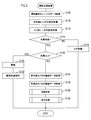
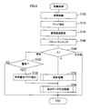
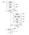
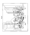
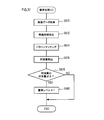
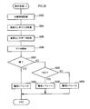
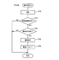
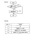
- FIG. 1 shows the example of application to the vehicle of the driving assistance device of embodiment. It is a block diagram which shows the structure of the driving assistance device of 1st Embodiment. It is a flowchart showing the flow of the handling assistance process which control ECU performs. It is a flowchart showing the flow of the extraction process which control ECU performs.
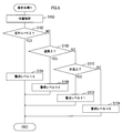
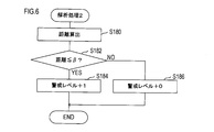
- 3 is a flowchart showing the flow of analysis processing 1; 6 is a flowchart showing a flow of analysis processing 2; 10 is a flowchart showing the flow of analysis processing 3; 6 is a flowchart showing a flow of analysis processing 4; 10 is a flowchart showing the flow of analysis processing 5; 10 is a flowchart showing the flow of analysis processing 6; 10 is a flowchart showing a subroutine flow of analysis processing 6; 10 is a flowchart showing the flow of analysis processing 7; It is a flowchart showing the flow of a vehicle recognition determination process. It is a flowchart showing the flow of a display data generation process. It is a flowchart showing the flow of an emphasized image generation process.
- FIG. 4 is a flowchart showing the flow of analysis processing 10. It is drawing explaining the detection of raindrops.
- 10 is a flowchart showing the flow of analysis processing 11.
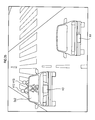
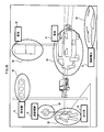
- 10 is a flowchart showing the flow of analysis processing 12; It is a flowchart showing the flow of a vehicle control process. It is drawing explaining the example of a display mode (1). It is drawing explaining the example of a display mode (2). It is drawing explaining the example of a display mode (3). It is drawing explaining the example of a display mode (4).
- DESCRIPTION OF SYMBOLS 1,100,101 ... Driving assistance device 2 ... Infrared radar, 3 ... Millimeter group radar, 4 ... Infrared camera, 5 ... Visible light camera, 6 ... Momentum amount detection unit, DESCRIPTION OF SYMBOLS 7 ... Head-up display (HUD), 8 ... Image projector, 9 ... Speaker unit, 10 ... Gaze detection unit, 11 ... Inter-vehicle communication unit, 12 ... Vehicle position sensor 20 ... Control ECU.
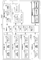
- the driving support apparatus 1 of the first embodiment includes an infrared radar 2, a millimeter wave radar 3, an infrared camera 4, a visible light camera 5, a momentum detection unit 6, and a head.
- An up display 7, a speaker unit 8, and a control ECU 20 are provided.
- FIG. 1 the image projector 9, the gaze detection unit 10, the inter-vehicle communication unit 11, and the vehicle position sensor 12 are shown.
- the driving assistance apparatus 1 is provided based on FIG.1 and FIG.2.
- the infrared radar 2 is a radar that detects the surrounding situation using infrared rays (in other words, detects the presence / absence of an object (hereinafter referred to as an object) and the distance to the object).
- the infrared radar 2 includes an infrared transmission / reception unit 2a, a signal processing unit 2b, and an external interface 2c.
- the infrared radar 2 irradiates infrared rays at the infrared transmission / reception unit 2a, and receives reflected light that is reflected by the object and returned.
- the signal processing unit 2b calculates the distance to the object based on the time difference between the irradiation time of the infrared rays and the reception time of the reflected light. Data representing the calculated distance is transmitted to the control ECU 20 via the external interface 2c.
- the distance that can be detected by the infrared radar 2 is about several tens of meters (for example, 20 to 30 m).
- the infrared radar 2 may be provided in a side part and a rear part in addition to the front part of the vehicle, as shown in FIG.
- the millimeter wave radar 3 is a radar that detects surrounding conditions using millimeter wave radio waves. As shown in FIG. 2, the millimeter wave radar 3 includes a millimeter wave transmission / reception unit 3a, a signal processing unit 3b, and an external interface 3c.
- the millimeter radar 3 receives the reflected wave that is reflected by the object and irradiated with the millimeter wave by the millimeter wave transmitting / receiving unit 3a. Then, the signal processing unit 3b calculates the distance to the object based on the time difference between the irradiation time of the millimeter wave and the reception time of the reflected wave. Data representing the calculated distance is transmitted to the control ECU 20 via the external interface 3c.
- the distance detectable by the millimeter wave radar 3 is up to about 150 m (or more). A resolution of about several tens of cm to 1 m is known.
- an object at a short distance up to several tens of meters
- a long distance from several tens of meters to 150 m (or more) is detected by the millimeter wave radar 3. Configured to detect the object.
- the infrared camera 4 is a camera that detects surrounding conditions by detecting infrared rays emitted from an object.
- the infrared camera 4 includes an infrared image sensor 4a, an image processing unit 4b, and an external interface 4c.
- the infrared camera 4 detects light (infrared rays) in the infrared region with the infrared image sensor 4a.
- the image processing unit 4b converts the infrared wavelength and intensity detected by the infrared image sensor 4a into an electrical signal, and generates an image based on the electrical signal.
- Data representing the generated image is transmitted to the control ECU 20 via the external interface 4c.
- this infrared camera 4 forms an image by detecting infrared rays emitted from an object, the object can be detected even in the absence of ambient light (such as sunlight) or headlight light. Therefore, the object can be detected even at night.
- the infrared camera 4 two infrared cameras 4A and 4B arranged at different positions are provided.
- the parallax difference in image position and viewing direction
- the infrared camera 4A and the infrared camera 4B Based on the fact that the parallax is correlated with the distance to the object, the distance to the object can be calculated according to the parallax.
- the infrared camera 4 refers to both the infrared cameras 4A and 4B unless otherwise specified.
- the visible light camera 5 is a camera that detects surrounding conditions by detecting reflected light of ambient light and headlight light.
- the visible light camera 5 includes a CCD image sensor 5a as an imaging device, an image processing unit 5b, and an external interface 5c.
- the visible light camera 5 detects light by the CCD image sensor 5a, and photoelectrically converts light and darkness of the detected light into a charge amount.
- the charge amount data is transferred to the image processing unit 5b.
- the image processing unit 5b generates a color image by reproducing color and brightness based on the charge amount data for each pixel.
- the generated image information is transmitted to the control ECU 20 via the external interface 5c.
- the visible light camera 5 is provided with two visible light cameras 5A and 5B arranged at different positions.
- the parallax is reproduced by the visible light camera 5A and the visible light camera 5B, and thereby a three-dimensional image can be generated. Further, as in the case of the infrared camera 4 described above, the distance to the object can be calculated.
- the momentum detection unit 6 is a unit for detecting the momentum of the host vehicle, and includes a vehicle speed sensor 6a, a yaw rate sensor 6b, and a steering angle sensor 6c.
- the traveling speed of the host vehicle is detected by the vehicle speed sensor 6a
- the yaw rate acting on the host vehicle is detected by the yaw rate sensor 6b
- the steering angle of the steering wheel is detected by the steering angle sensor 6c.
- the detection signal is transmitted to the control ECU 20.
- a head-up display (HUD: Head Up Display) 7 is a device that superimposes and displays an image on a vehicle window (in the example, a front window).
- the HUD 7 has a laser projector 7a, performs signal processing by the laser projector 7a based on a signal from the control ECU 20, generates an image, and displays the image via an optical unit 7b including a mirror and a lens. .
- the image is formed on the virtual image plane so as to be superimposed on the scenery outside the vehicle viewed through the front window.
- the virtual image plane is formed in front of the front window, so that the driver of the vehicle can recognize that the image is displayed in the viewable scenery.
- the speaker unit 8 is a device that emits sound (including sound) around the vehicle based on control by the control ECU 20.
- the control ECU 20 is an electronic control device that includes a CPU 20a, a ROM 20b, a RAM 20c, a flash memory 20d, a communication interface 20e, and the like, and executes various processes.
- the control ECU 20 repeatedly executes the driving support process of FIG. 3 at a predetermined cycle while the vehicle is traveling. Accordingly, the driving support device 1 detects the environment around the vehicle, recognizes an object (person, vehicle, etc.), and notifies the vehicle driver of the presence of the object (in other words, gives a warning).
- the driving support device 1 detects the environment around the vehicle, recognizes an object (person, vehicle, etc.), and notifies the vehicle driver of the presence of the object (in other words, gives a warning).
- detection data is acquired from the momentum detection unit 6, and the momentum of the host vehicle is estimated based on the acquired vehicle speed, yaw rate, and steering angle.
- a signal from the infrared radar 2 is acquired.
- the process proceeds to S112, and a signal from the millimeter wave radar 3 is acquired.
- S114 based on the signal from the infrared radar 2 and the signal from the millimeter wave radar 3, it is determined whether or not an object exists in the detection range.
- the process proceeds to S116 to store a log indicating that the object does not exist, and then the process is terminated. This log may be stored in the flash memory 20d.
- S118 based on the distance data to the object obtained from the infrared radar 2 signal and the millimeter wave radar 3 signal, it is determined whether or not the distance to the object is equal to or less than a preset threshold value ⁇ .
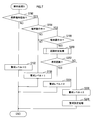
- the threshold value ⁇ is appropriately set to a value that causes a risk of collision.
- a fixed value may be set as the threshold value ⁇ .
- a value that is determined to cause a collision risk in relation to the host vehicle traveling at the momentum is calculated by calculation. It may be set.
- processing for warning the driver of the vehicle is executed.
- the HUD 7 is controlled to display a warning superimposed on, for example, the front window of the vehicle.
- a warning display a message or a symbol indicating that there is a risk of collision may be displayed.
- a collision avoidance command for avoiding a collision with the object is transmitted to an ECU (not shown) that controls the operation of the vehicle. Specifically, a collision avoidance command is transmitted to the brake control ECU, the steering control ECU, etc., and brake control and steering control for avoiding the collision are executed. Thereafter, the process ends.
- S124 image data is acquired from the infrared camera 4.
- either one of the image data of the infrared cameras 4A and 4B or both of them may be acquired.
- an average value of the two image data may be calculated and used.
- a highly accurate portion (a portion with less noise or the like) may be extracted from each of the two image data, and data combining them may be generated and used.
- image data is acquired from the visible light camera 5.
- image data of the visible light cameras 5A and 5B may be acquired, or both may be acquired.
- an average value of the two image data may be calculated and used.
- a highly accurate portion (a portion with less noise or the like) may be extracted from each of the two image data, and data combining them may be generated and used.
- processing for recognizing and analyzing the object (hereinafter, recognition processing) is executed. Details of the recognition process will be described later.
- S130 a display process for displaying information on objects around the vehicle based on the result of the recognition process in S128 is executed. In other words, this process is a process of notifying the driver of the presence of the object by displaying a predetermined image. Details of the display process will be described later.
- the process proceeds to S142, and an edge in the image (a portion where the amount of change in luminance (brightness / darkness) is larger than a predetermined threshold) is extracted.
- This process is based on the premise that the amount of change in luminance becomes large at the boundary between, for example, a person or a vehicle and the background.
- candidates for areas occupied by the same object are set based on the edge information extracted in S142. For example, as described above, it is assumed that the amount of change in luminance is large at the boundary between a person or vehicle and the background, but the amount of change in luminance is not always large at all boundaries, and the edges may be interrupted. obtain. In this processing, the range (area) of the same object determined by the edge is set (estimated) while recognizing the break of the edge from the data of the peripheral edge.
- the process proceeds to S146, and pattern matching is performed on the region set in S144 (more specifically, on the estimated object) with a pattern stored in advance and a past learning value (learned pattern), and the object Estimate what is In this pattern matching, a person (including a person riding a bicycle or the like), a vehicle, an animal (pet or the like), and an installation (a guardrail, a sign, a traffic light, a signboard or the like) can be recognized.
- S150 it is determined whether or not to notify the driver of the own vehicle of the extracted vehicle information (whether or not to warn). For example, it may be configured to be able to set in advance whether or not to notify the driver of the vehicle of vehicle information. And in S150, you may determine based on the setting. Alternatively, the positional relationship between the vehicle and the host vehicle, the relative speed, and the like may be detected, and the risk may be determined based on the detected position.
- warning display data is generated based on the analysis processing result in S152 and the determination result in S150.
- the data generated here is used in the display process in S130. Specifically, in S130, the data generated in S154 is transmitted to the HUD 7, and a warning image is displayed on the HUD 7.
- the analysis processing in S152 will be specifically described with reference to FIGS.
- the analysis processes 1 to 7 in FIGS. 5 to 12 (and FIG. 13) are executed in parallel or sequentially in a predetermined order.
- the analysis processes 1 to 7 are executed for each object recognized as “person” in S148 described above.
- a warning level for the object (person) is set according to the analysis result.
- the alert level is data used in the process of S154. Specifically, it is data for determining in what manner the warning is displayed to the driver of the vehicle.
- the alert level is represented by a numerical value. As the numerical value increases, display data is generated so that a warning is displayed in a manner that is more easily recognized by the driver of the vehicle.
- the analysis process 1 in FIG. 5 is a process of analyzing a position (location) where an object (person) exists and setting a warning level according to the position.
- a process for analyzing the position where the object (person) exists is executed. Specifically, the distance from the host vehicle, the relative position with respect to other objects, and the like are analyzed by image analysis of a captured image by the infrared camera 4 or the visible light camera 5. The distance from the host vehicle can be calculated using the parallax of the infrared cameras 4A and 4B or the parallax of the visible light cameras 5A and 5B.
- the signal from the infrared radar 2 acquired in S110 and the signal from the millimeter radar 3 acquired in S112 include information on the distance to the object.
- the distance calculated in S160 may be calculated or corrected.
- the distance may be calculated from the signals acquired in S110 and S112. After S160, the process proceeds to S162, and it is determined whether an object (person) exists on the traveling route of the host vehicle.
- the road on which the host vehicle is traveling is recognized by image analysis at the stage of the processing of S160 described above. Further, for the process of S170 described later, a sidewalk may be added and recognized.
- the movement direction (traveling direction) of the host vehicle is estimated based on the data on the amount of movement of the host vehicle acquired in S100. Based on these processes, it is determined whether or not the object (person) exists on the recognized road and on the estimated traveling direction of the own vehicle, so that the object (person) Determine if it exists above.
- the process proceeds to S164.
- the value of the alert level for the object (person) is incremented by 3 points. Thereafter, the process ends.
- the value of the alert level is incremented in the range of 1 to 3.
- “+0” is described in the flowchart. This value is an example, and any value may be set as appropriate.
- the numerical value of the alert level is stored in the flash memory 20d in association with the object (person). If it is determined in S162 that the object (person) does not exist on the travel route of the host vehicle, the process proceeds to S166.
- S166 it is determined whether or not the object (person) exists on the road on which the host vehicle is traveling. If it is determined in S166 that the object (person) exists on the road, the process proceeds to S168.
- S170 it is determined whether an object (person) exists on the sidewalk. If it is determined in S170 that the object (person) exists on the sidewalk, the alert level is incremented by one point.
- the analysis process 2 will be described with reference to FIG.
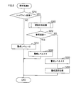
- the analysis process 2 in FIG. 6 is a process of calculating the distance from the host vehicle to the object (person) and setting the alert level according to the calculated distance.
- the distance from the own vehicle to the object (person) is calculated.
- the calculation method is as described above.
- the process proceeds to S182, and it is determined whether or not the distance calculated in S180 is equal to or less than a predetermined threshold value ⁇ .
- the value of ⁇ can be set as appropriate.
- the analysis process 3 will be described with reference to FIG.
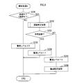
- the analysis process 3 in FIG. 7 is a process for analyzing whether or not an object (person) is carrying and operating a portable terminal (and whether or not the vehicle is recognized) and setting a warning level based on the result. It is.
- the analysis process 3 first, in S190, it is determined whether or not the object (person) is carrying (gripping) the portable terminal.
- the presence / absence (presence) of the portable terminal is recognized by image analysis (pattern matching) in the processing of S140 to S146 described above.
- image analysis pattern matching
- the luminance (brightness) of the display screen portion is high, and edge extraction with relatively high accuracy is possible.
- recognition by pattern matching becomes easy.
- edge extraction can be performed based on a difference in luminance (brightness and darkness) from a human hand when the portable terminal is held by the human hand. Therefore, in any case, recognition by pattern matching is possible.
- S190 if it is determined in S190 that the object (person) is carrying (holding) the portable terminal, the process proceeds to S194.
- S194 it is determined whether or not the mobile terminal is operating.
- the mobile terminal is operating from the brightness (brightness and darkness) in the area recognized as the mobile terminal. This is intended to make a determination on the assumption that the luminance (brightness) of the portion of the display screen in the portable terminal is high when the portable terminal is in operation.
- the process proceeds to S196.
- the alert level is incremented by 1 point based on the determination that the object (person) is holding the mobile terminal although the mobile terminal is not operating. Thereafter, the process is terminated.
- the process proceeds to S198. Note that the process of S194 may be omitted. Specifically, if it is determined in S190 that the object (person) is carrying (gripping) the portable terminal, the process may proceed to S198 without executing the process of S194.
- S198 it is determined whether or not the object (person) is operating the mobile terminal.
- the position of the portable terminal, the position of each part (hand, face) in the object (person), the orientation of the face, and the like are analyzed and comprehensively determined from the information.
- S198 If it is determined that the operation is not being performed in S198, the process proceeds to S196. On the other hand, if it determines with operating in S198, it will transfer to S200. In S200, a process of determining whether or not the object (person) recognizes the presence of the host vehicle (hereinafter, a recognition determination process) is executed.
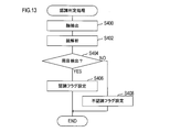
- FIG. 13 shows the recognition determination process.
- the recognition determination process in S200 recognition determination process in FIG. 13
- a face area in the object (person) is extracted.
- step S404 it is determined whether both eyes have been detected.
- a recognition flag indicating that the object (person) recognizes the presence of the host vehicle is set. Thereafter, the process is terminated. On the other hand, if it is determined in S404 that both eyes cannot be detected, it is determined that the host vehicle may not exist within the field of view of the object (person). Based on this determination, the object (person) A simple determination is made that the presence of the vehicle is not recognized, and the flow proceeds to S408.
- a determination process based on the recognition flag set in S406 or the non-recognition flag set in S408 (specifically, a determination process as to whether or not the object (person) recognizes the presence of the host vehicle). )I do.
- the process proceeds to S204.
- the alert level is incremented by 2 points based on the determination that the object (person) recognizes the existence of the own vehicle while the portable terminal is being operated. Thereafter, the process is terminated.
- the process proceeds to S206.
- the alert level is incremented by 3 points based on the determination that the object (person) is operating the mobile terminal and does not recognize the presence of the host vehicle.
- the warning setting process includes a flag for displaying an image for notifying (warning) the driver that the object (person) has not recognized the existence of the own vehicle, and an alarm process for the object (person). This is a process of setting a flag to the effect. This flag is stored in association with the target object (person).
- a warning image for notifying (warning) the driver that the object (person) has not recognized the presence of the own vehicle is generated.
- the vehicle is superimposed and displayed on the front window.
- an alarm is issued to the object (person) through the speaker unit 8 (see FIGS. 1 and 2) by a separate process.
- the analysis process 4 in FIG. 8 is a process of analyzing whether or not the object (person) is using the headphones (and whether or not the vehicle is recognized), and setting a warning level based on the result. .
- S210 it is determined whether or not the object (person) is using headphones or earphones (hereinafter simply referred to as headphones).
- the determination is made based on the result of image analysis (the processing of S140 to S146).
- the process proceeds to S218.
- the alert level is incremented by 1 point based on the determination that the object (person) recognizes the presence of the host vehicle and uses the headphones. Thereafter, the process is terminated.
- the process proceeds to S220.
- the warning level is incremented by 3 points based on the determination that the object (person) is using headphones and does not recognize the presence of the host vehicle.
- the analysis process 5 in FIG. 9 is a process for analyzing whether or not the object (person) is talking or talking (and whether or not the vehicle is recognized) and setting a warning level based on the result. is there.
- the analysis process 5 first, in S230, it is determined whether or not the object (person) is talking or talking. Here, the determination is made based on the result of image analysis (the processing of S140 to S146).
- the process proceeds to S238.
- the alert level is incremented by 1 point based on the determination that the object (person) recognizes the presence of the own vehicle while talking or talking. Thereafter, the process is terminated.
- the process proceeds to S240.
- the alert level is incremented by 3 points based on the determination that the object (person) is talking or talking and does not recognize the presence of the vehicle.
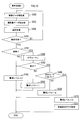
- the analysis process 6 in FIG. 10 is a process of analyzing the movement of an object (person) and setting a warning level based on the result.
- image data is re-acquired from the infrared camera 4 or the visible light camera 5 in S250.
- tracking processing between a plurality of images (between frames) is executed for the object (person). Specifically, the similarity of objects (people) is calculated in the current image (current frame) and the image (frame) in the past, and objects (people) with high similarity are the same object (people). The same label is assigned because it is determined that there is a high possibility that As the similarity index, the size (area) of the region, luminance (brightness / darkness), movement amount, and the like are used. Here, the size (area) of the object (person), the amount of movement, and the like are corrected in consideration of the amount of movement of the host vehicle. The objects (people) with the same label are analyzed in time series, and the presence / absence of movement and the movement direction are calculated.
- the process proceeds to S256, and it is determined whether or not the movement of the object (person) can be analyzed. In other words, it is determined whether the re-acquired image data and exercise amount data are sufficient for recognizing or estimating the movement of the object (person).
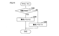
- FIG. 11 is a flowchart showing the flow of subroutine processing in S280.
- S280 subroutine processing of FIG. 11
- S282 it is determined whether or not the moving direction of the object (person) is the same as the moving direction of the host vehicle.
- the alert level is incremented by 2 points. Thereafter, the process is terminated.
- the process proceeds to S286, and then the process is terminated without incrementing the alert level.
- the process proceeds to S262 in FIG. In S262, it is determined whether or not the object (person) is meandering. As for the meanders, there are warnings about wobbling due to drinking, wobbling due to two-seater bicycles, and the like.
- the process proceeds to S264 based on the judgment that the object is not meandering but is moving, and the warning level is incremented by one point. Thereafter, the process is terminated.
- the process proceeds to S268 based on the determination that the object (person) is not approaching but is meandering, and the warning level is incremented by 2 points. Thereafter, the process is terminated.
- the process proceeds to S270, and the warning level is incremented by 3 points.
- the process proceeds to S272, and a flag for displaying an image indicating the moving direction of the object (person) is set.
- this flag is set, an image indicating the moving direction of the object (person) is generated in the process of S154 in FIG. 4, and the image is displayed in the process of S130 in FIG.
- This series of processing is executed with the purpose of calling attention to the driver of the vehicle by displaying an image indicating the moving direction of the object (person).
- the analysis process 7 will be described with reference to FIG.
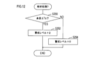
- the analysis process 7 in FIG. 12 is a process for simply determining whether or not the object (person) is a child and setting a warning level based on the result.
- the height (height) of the object (person) is equal to or less than a predetermined threshold value Ta.
- a predetermined threshold value Ta an average height of a person (child) of an age to be discriminated may be assigned.
- processing for generating an image for emphasizing the object (person) is executed for each object (person) according to the extracted alert level.
- the enhanced image generation process will be specifically described with reference to FIG.
- S504 enhanced image generation process of FIG. 15
- S520 an image surrounding the object area is generated in accordance with the object area of each object (person).
- a triangle, a quadrangle, a circle, an ellipse, or the like can be set as appropriate.
- a vertically long image can be generated for a standing object (person), and an image with a substantially equal aspect ratio can be generated for a sitting object (person), for example.
- a horizontally long image is generated for an object (person) that has fallen down.
- the process proceeds to S522, and the display mode of the image generated in S520 is set according to the alert level extracted in S502 described above. Specifically, the thickness of the frame line, the color of the line, etc. are set. It is also set whether to blink display.
- the higher the alert level the thicker the line.
- the line color may be set to a color (red, yellow, other fluorescent color, etc.) that attracts the driver's attention.
- the image may be set to blink.
- Each object (person) may be classified as a group with a high point, an intermediate group, or a low group according to the set alert level point. And the display mode of an image may be set for every group.
- S524 it is determined whether images have been set for all objects (people). If it is determined in S524 that no image has been set for all objects (persons) (an unset object (person) exists), the process returns to S520 (and S522).
- a flag for warning the vehicle (hereinafter, vehicle warning flag) is set. This flag is set in the process of S156 in FIG. If it is determined in S506 that the vehicle warning flag is set, the process proceeds to S508, and an image for emphasizing the object (vehicle) is generated in association with the target object (vehicle). Specifically, an image surrounding the object area of the object (vehicle) recognized in the processes of S140 to S148 in FIG. 4 is generated. As an image surrounding the object region, a triangle, a quadrangle, a circle, an ellipse, or the like can be set as appropriate. After the processing of S508, the process proceeds to S510.
- S510 whether or not a flag (hereinafter referred to as an unrecognized notification flag) for displaying an image for notifying (warning) the driver that the object (person) has not recognized the presence of the host vehicle is set. Determine whether. This flag is set in the processing of S208 in FIGS.
- a warning image for the driver is generated in association with the target object (person).
- This warning image is an image for notifying (warning) the driver that the object (person) has not recognized the presence of the own vehicle.
- the image is not limited to a mark such as a symbol, but may be a message, for example. Alternatively, an image surrounding the face portion of the object (person) may be used.
- the color of the warning image may be a color (red, yellow, other fluorescent color, etc.) that further prompts the warning.
- S510 If it is determined in S510 that the unrecognition notification flag is not set, the process proceeds to S514. In S514, it is determined whether or not a flag for displaying an image indicating the moving direction of the object (person) (hereinafter referred to as a moving display flag) is set. This flag is set in the process of S272 of FIG.
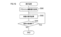
- an alignment adjustment signal for initializing and adjusting the display position and the imaging position by the HUD 7 is transmitted to the HUD 7. This causes the HUD 7 to execute adjustment (initialization) of the display position and the imaging position.
- a signal representing an image generated in the display data generation process of S154 (display data generation process shown in FIGS. 14 and 15) is transmitted to the HUD 7.
- the image is superimposed and displayed on the front window of the vehicle via the HUD 7.
- the signal representing the image includes data of coordinate values (coordinate values based on the display area by the HUD 7) at which the image is to be displayed.
- control ECU 20 includes information on coordinate axes (hereinafter referred to as camera coordinate axes) based on the imaging areas of the infrared camera 4 and the visible light camera 5 and coordinate axes (hereinafter referred to as HUD coordinate axes) based on the display area of the HUD 7. Have both information. Then, the coordinate value (the coordinate value indicating the position to be displayed by the HUD 7) on which the image generated by the image analysis of the infrared camera 4 or the visible light camera 5 is to be displayed is changed from the coordinate value on the camera coordinate axis on the HUD coordinate axis. Calculated by converting to coordinate values.
- coordinate axes hereinafter referred to as camera coordinate axes
- HUD coordinate axes coordinate axes
- S542 the process proceeds to S544, and it is determined whether there is an additional display image. Specifically, it is determined whether or not a new image is generated by the display data generation process of S154. If it is determined in S544 that there is an additional image, the process of S542 is executed again.
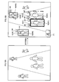
- FIG. 17 First, the example of FIG. 17 will be described.
- an object H that is a person and objects V0, V1, and V2 that are vehicles are extracted and recognized.
- an image for emphasis is superimposed and displayed for both a person and a vehicle.
- an oval frame image (hereinafter also simply referred to as a frame) W surrounding the object H is displayed.
- a frame an oval frame image
- elliptical frames X0, X1, and X2 that surround the objects V0, V1, and V2 are displayed.
- the display mode may be different between the frame W and the frames X0, X1, and X2.
- the frame W may be displayed as a solid line
- the frames X0, X1, and X2 may be displayed as a broken line.
- the object V0 and the object V2 are seen partially overlapping (part of the object V2 is behind the object V0).
- the positional relationship between the object V0 and the object V2 may be grasped from the stereoscopic information (depth information).
- the control ECU 20 is configured not to recognize the object V0 and the object V2 as different objects based on the three-dimensional information (depth information) but as different objects.
- a frame X0 corresponding to the object V0 and a frame X2 corresponding to the object V2 are drawn.
- the frame X0 and the frame X2 may also include stereoscopic information (depth information).
- the frame X2 may be displayed so that a part of the frame X2 is hidden behind the object V0.
- a mode display area R is shown at the upper right of the drawing. This area is an area for displaying a target for displaying an image for emphasis (specifically, a target symbol mark).
- a vehicle symbol Mv and a human symbol Mp are shown in the mode display area R. This indicates a mode in which an image for emphasis (frame W and frames X0, X1, and X2 in FIG. 17) is displayed for the vehicle and the person.
- an image (frame W) for detecting an object (person, other vehicle) or the like around the host vehicle and causing the driver to visually recognize the detected object is displayed on the object. It is superimposed and displayed in association. For this reason, it is easier for the driver to recognize the object.
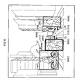
- FIGS. 18A and 18B Next, an example of FIGS. 18A and 18B will be described.
- the driving support device 1 analyzes the state of each person by image analysis for each of the four persons, and displays a warning image corresponding to the analyzed state.
- a frame W (W1, W2, W3, W4) for emphasis is displayed for each of the objects H1 to H4.
- the frame W may be generated and displayed so as to surround the areas of the objects H1 to H4.
- the frame W may be configured to be generated and displayed vertically.
- the frame W may be configured to be generated and displayed horizontally.
- the frame W may be generated and displayed so that the aspect ratio of the frame W is approximately equal.
- the display modes of the frames W1 to W4 differ depending on the alert level.
- the objects H1 and H2 exist in the travel route of the host vehicle. In particular, it is assumed that the distance from the host vehicle is equal to or less than a predetermined threshold value ⁇ for the object H1.
- the frame W1 is displayed in a display mode that is more emphasized.
- the frame W1 may be configured with a double frame. Further, it may be displayed in a more conspicuous color such as a fluorescent color.
- the distance from the host vehicle is greater than a predetermined threshold ⁇ for the object H2. Accordingly, when the alert level is set relatively low (compared to the object H1) for the object H2, the degree of emphasis of the frame W2 may be suppressed in comparison with the frame W1.
- the frame W2 may be displayed blinking, for example.
- the driving support apparatus 1 determines that the objects H1 and H2 are in conversation, the driving support apparatus 1 displays the conversation symbols M1 and M2 indicating that the objects are in conversation in the vicinity of the frames W1 and W2 in association with the objects H1 and H2. You may do it.
- Data of conversation symbols M1 and M2 is stored in the flash memory 20d. Note that the data of the conversation symbols M1 and M2 may be stored in the ROM 20b. The same applies to a portable terminal symbol M3, a headphone symbol M4, an unrecognized symbol M1 ′, and a recognized symbol M2 ′ described later.
- the vicinity is a position adjacent to (or in contact with) the frame W regardless of whether it is up, down, left, or right with respect to the frame W.
- it may be within the area of the frame W.
- the conversation symbols M1 and M2 may be displayed superimposed on the areas of the frames W1 and W2. The meaning of “near” is the same in the following.
- an unrecognized symbol M1 ′ representing that fact may be superimposed on the vicinity of the frame W1 in association with the object H1.
- a recognition symbol M2 ′ representing that fact is superimposed on the vicinity of the frame W2 in association with the object H2. You may display.
- a mobile terminal symbol M3 indicating that may be displayed in a superimposed manner in the vicinity of the frame W3 in association with the object H3.
- the headphone symbol M4 indicating that may be displayed in the vicinity of the frame W4 in association with the object H4.
- the driving support device 1 may set an auxiliary display area P1 for displaying auxiliary information.
- the number of extracted objects may be displayed in the auxiliary display area P1.
- the number of persons displayed in the auxiliary display area P1 may be the number of persons displaying an image for emphasis.
- the numerical value of the number of people may be incremented according to the addition.
- the numerical value of the number of people may be decremented and displayed in accordance with the erase. Further, when the number of people is the same but the object is changed, the fact may be notified by flashing a numerical value or the like.
- the symbols M1 to M4, M1 ′, and M2 ′ may be deleted or changed according to changes in the states of the objects H1 to H4.
- the driving support device 1 when the object is a person, information indicating the state of the person is displayed, so the driver recognizes not only the presence of the person but also the state of the person. become able to. For this reason, it becomes possible for the driver to realize driving according to the conditions of people around the vehicle. That is, it can contribute to improving driving safety.
- FIG. 19 Next, the example of FIG. 19 will be described.
- four objects H5, H6, H7, and H8 are extracted.
- Objects H5 and H6 are pedestrians walking on a pedestrian crossing, and objects H7 and H8 are people riding bicycles.
- Objects H5, H6, H7, and H8 are surrounded by frames W5, W6, W7, and frame 8 for emphasis, respectively.
- the display mode of W5, W6, W7, and the frame 8 may be different depending on the distance from the host vehicle to the objects H5, H6, H7, and H8, for example.
- the line thickness may be different.
- the object H5 is closest to the own vehicle, and the frame 5 corresponding to the object H5 is displayed with the thickest line.
- the object H8 is farthest from the host vehicle, and the frame 8 corresponding to the object H8 is displayed by the thinnest line.
- an arrow image (hereinafter, also simply referred to as an arrow) Y indicating the traveling direction of the object is displayed in association with each object H.
- arrows Y5 and Y7 are directed to the right side in the drawing, indicating that the objects H5 and H7 are traveling toward the right side.
- An arrow Y6 is directed toward the left side in the drawing, and indicates that the object H6 is traveling toward the left side.
- the arrow Y8 is directed toward the own vehicle, indicating that the object H8 is approaching the own vehicle.
- the arrow Y may indicate the moving speed of each object H.
- the magnitude of the moving speed may be indicated by the length of the arrow Y.
- arrows Y5, Y6, and Y7 whose lengths are easily compared are targeted.
- the length of the arrow Y7 is the longest and the moving speed of the object H7 is the highest.
- the arrow Y6 is the shortest and the moving speed of the object H6 is the lowest.
- the length of the arrow Y5 is intermediate between the arrows Y7 and Y6, and the moving speed of the object H5 is between the moving speed of the object H7 and the moving speed of the object H6.
- arrow gradation portions G5, G6, G7 may be drawn, and the magnitude of the moving speed may be indicated by the length, density, etc. of the gradation portions.
- the magnitude of the moving speed may be indicated by the position of the arrow Y with respect to the frame W (or the object H).
- arrows Y5, Y6, and Y7 that can be compared in the height direction with respect to the frame W (or the object H) are targeted.
- the arrow Y7 is shown further upward in the range in the height direction of the frame W7 (and the object H7).
- the arrow Y5 is shown around the middle in the range in the height direction of the frame W5 (and the object H5).
- the arrow Y6 is shown below in the range in the height direction of the frame W6 (and the object H6).
- the moving speed of the object H7 is the highest at the position of the arrow Y7 (the position in the vertical direction) shown above in relation to the object H. Further, it may be indicated that the moving speed of the object H6 is the lowest at the position of the arrow Y6 (vertical direction position) shown below in relation to the object H. In addition, even if the position of the arrow Y5 (vertical direction position) indicated at an intermediate position in relation to the object H indicates that the moving speed of the object H5 is intermediate between the object H7 and the object H6. good.
- the driving support device 1 since the information indicating the direction in which the person around the vehicle is moving and the moving speed thereof is displayed, it is easy for the driver to predict the movement of the person. For this reason, it can contribute to improving the safety of driving.
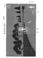
- the example of FIG. 20 is a display example at night.
- the object H9 is extracted and recognized.
- a frame W9 for emphasizing the object H9 is superimposed and displayed.
- the frame W9 may be drawn with a white color or a fluorescent color so that the frame W9 is easily visible at night.
- an arrow symbol M9 is displayed to enhance the effect of attracting the driver's attention.
- the arrow symbol M ⁇ b> 9 faces the object H ⁇ b> 9 rather than the moving direction of the object H ⁇ b> 9 and strengthens the presence of the object H ⁇ b> 9.
- the arrow symbol M9 is arranged so that when the line of sight is moved in the direction of the arrow, the object H9 is naturally recognized (so that it comes to the center of the field of view).
- the driving support device 1 may be configured to display the frame W9 and the arrow symbol M9 at the same time when the object H9 is detected.
- the frame W9 may be displayed and the arrow symbol M9 may be additionally displayed after a predetermined time has elapsed. According to the latter configuration, the enhancement effect can be further enhanced.
- a caution symbol M9 ' is displayed on the left side of the frame W9.
- the attention symbol M9 ' can also be displayed to enhance the effect of attracting the driver's attention, like the arrow symbol M9.
- the display position of the attention symbol M9 '(and the arrow symbol M9) may be any position as long as it is easily recognized in relation to the background.
- the frame W9 (and the object H)) may be displayed in the lower left area Ra.
- it may be displayed in the region Rb directly below the frame W9 (and the object H)).
- the background is displayed in a region where the luminance (brightness / darkness) does not vary (in other words, a region where the luminance (brightness / darkness) is constant).
- auxiliary display areas P2 to P4 may be set.
- a symbol mark h9 representing the object H9 is displayed in the auxiliary display area P2.
- the symbol mark h9 may be displayed in the auxiliary display area P2.
- Such a mode may be set by the driver using an input device operated by the driver.
- the distance is displayed in the auxiliary display area P3. This distance represents the distance from the host vehicle to the object H9.
- a symbol m9 that is the same symbol as the attention symbol M9 ′ is displayed.
- the attention symbol M9 ′ and the symbol m9 may be displayed in conjunction with each other. For example, the symbol m9 may be automatically displayed when the attention symbol M9 ′ is displayed. Further, when the attention symbol M9 ′ is deleted, the symbol m9 may also be deleted.
- the driving assistance device 1 it is possible to appropriately support the driver visually recognizing the surrounding situation at night or the like when the visibility is lowered for the driver. For this reason, it can contribute to improving driving safety even at night.
- the infrared radar 2, the millimeter radar 3, the infrared camera 4, and the visible light camera 5 correspond to an example of a detection unit
- the processes of S114, S128, and S140 to S148 correspond to an example of a recognition unit.
- the processing of S152 corresponds to an example of analysis means, and S164, S168, S172, S174, S184, S186, S192, S196, S204, S206, S208, S212, S218, S220, S232, S238, S240, S260,
- the processing of S264, S268, S270, S284, S286, S292, S294, and S660 corresponds to an example of a setting unit
- the processing of S154 corresponds to an example of a generation unit
- the processing of HUD7 and S130 corresponds to an example of a display unit. To do.
- the process of S148 corresponds to an example of a determination unit
- the ROM 20b or the flash memory 20d corresponds to an example of a storage unit.
- the conversation symbols M1, M2, the mobile terminal symbol M3, and the headphone symbol M4 correspond to examples of symbolic symbols.
- the driving support device 100 (see FIG. 21) of the second embodiment is different from the driving support device 1 (see FIG. 2) of the first embodiment in that an image projecting device 9 is provided.
- the driving support device 100 is different from the driving support device 1 in the following points. First, instead of the recognition process of FIG. 4, the recognition process (2) of FIG. 22 is executed.
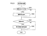
- the analysis process 8 of FIG. 24 is performed. Further, instead of the display process of S130 in FIG. 3 (display process of FIG. 16), the display process (2) of FIG. 25 is executed.
- the image projecting device 9 is a device for projecting an image to an area in an environment outside the vehicle, which can project an image as a screen.
- a region where an image can be projected as a screen can be detected by analyzing an image captured by the infrared camera 4 or the visible light camera 5.
- the image projector 9 has a laser projector 9a, performs signal processing by the laser projector 9a based on a signal from the control ECU 20 (in other words, generates a display image signal), and includes an optical system including a mirror, a lens, and the like. An image is projected through the unit 9b.
- the screen determination process is a process for determining whether or not an image can be projected onto the area of the object determined to be “other”.
- the control ECU 20 first determines whether or not the area of the object region is equal to or larger than the predetermined area S in S560.
- This process is a process for determining whether or not the image has a sufficient area (area) for projecting an image.
- S562 it is determined whether the distance from the host vehicle to the object is a distance at which an image can be projected. If it is determined in S562 that the distance is not projectable, the process ends.
- the difference and variation in the brightness (brightness and darkness) of the image increases as the degree of unevenness of the surface of the object region increases.
- the smaller the unevenness of the surface of the object area the smaller the difference and variation in the luminance (brightness) of the image.
- the flatness is estimated by analyzing the difference (brightness and darkness) in the luminance (brightness and darkness) of the image of the object region.
- the process proceeds to S566, and it is determined whether or not the estimated flatness is equal to or less than a predetermined threshold F (assuming that the smaller the flatness value is, the flatter it is). If it is determined in S566 that the flatness is not less than or equal to the predetermined threshold value F, the process is terminated.
- a predetermined threshold F assuming that the smaller the flatness value is, the flatter it is.
- the characteristic that the absorption rate of infrared rays varies depending on the color of the surface irradiated with infrared rays is used.
- White objects have a relatively low infrared absorption rate (in other words, infrared reflectance is relatively high.
- black objects have a relatively high infrared absorption rate (in other words, infrared reflectance). Is relatively low).
- the infrared absorption rate of the object can be calculated by analyzing the intensity of the reflected infrared light irradiated by the infrared sensor 2 in consideration of the distance to the object. Based on the calculation result, the color of the object can be estimated.
- the color of the surface of the object area is estimated using the infrared sensor 2 by the method described above. After S568, the process proceeds to S570, and based on the estimation result in S568, it is determined whether or not the color of the surface of the object region is a color capable of projecting an image.
- S570 If it is determined in S570 that projection is not possible, the process ends. On the other hand, if it determines with projection being possible in S570, it will transfer to S572. In S572, a flag (projectable flag) indicating that an image can be projected as a screen is set for the target object region.
- the control ECU 20 further executes an analysis process 8 as one of the analysis processes of S152 in FIG.
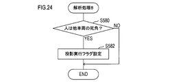
- FIG. 24 shows the flow of the analysis process 8.
- the control ECU 20 first determines in S580 whether or not a person exists in the blind spot of the vehicle (other vehicle) from the extracted positional relationship between the person and the vehicle. In this determination, the traveling direction of the other vehicle, the person and the objects (obstacles) around the other vehicle are extracted, and it is comprehensively determined whether or not the person exists in the view area of the driver of the other vehicle.
- S590 it is determined whether the projection enable flag and the projection execution flag are set.
- the projectable flag is a flag set in the above-described processing of S572 (see FIG. 23).
- the projection execution flag is a flag set in the process of S582 described above (see FIG. 24).
- the process proceeds to S592.
- the information (specifically, information on the coordinate value, range, area, etc.) of the object area that can be projected as a screen and stored in S574 is transmitted to the image projection device 9.
- image data to be projected on the image projection device 9 is transmitted to the image projection device 9.
- This image data may be a part or all of the data of the image captured by the infrared camera 4 or a part or all of the data of the image captured by the visible light camera 5.
- generated by the process (refer FIG. 22) of S154 may be included.
- the image projecting device 9 can project an image onto a predetermined region (region in which an image can be projected) in the environment around the vehicle. .
- the driving support apparatus 100 is mounted on a vehicle (own vehicle) K1. There is another vehicle K2 around the host vehicle K1. There are also objects H10 and H11.
- the object H10 is a bag and the object H11 is a person (here, a duo). In FIG. 26, only the top of one person's head is visible. When viewed from the direction of the other vehicle K2, the object H11 is hidden behind the object H10. That is, a positional relationship is formed in which the object H10 cannot be visually recognized by the driver of the other vehicle K2.
- the driving support device 100 of the host vehicle K1 detects the objects H10 and H11 by analyzing the image data of the infrared camera 4 or the image data of the visible light camera 5. Further, the other vehicle K2 is detected.
- a screen determination process is executed to determine whether an image can be projected as a screen. Further, the positional relationship between the objects H10 and H11 and the other vehicle K2 is analyzed, and it is determined whether or not the object H11 is within the field of view of the driver of the other vehicle K2.
- the driving support apparatus 100 transmits the image data of the object H11 to the image projection apparatus 9, and projects the image of the object H11 on a predetermined area (screen area that can project an image as a screen) Sc1 in the object H10. .
- the driver displayed on the screen area Sc1 of the object H10 indicates that the driver of the other vehicle K2 has the presence of the object H11. Can be recognized.
- the driving support device 101 (see FIG. 27) of the third embodiment is different from the driving support device 1 (see FIG. 2) of the first embodiment in that it includes a line-of-sight detection unit 10.
- the driving support device 101 is different from the driving support device 1 in that the driving support processing (2) in FIG. 29 is executed instead of the driving support processing in FIG.
- the line-of-sight detection unit 10 is a device that is mounted in a vehicle and detects the line of sight by tracking the movement of the eyeball (pupil) of the driver of the vehicle by image recognition.
- the line-of-sight detection unit 10 includes a CCD image sensor 10a, an LED light source 10b, and an image processing unit 10c.
- the LED light source 10b irradiates invisible near infrared rays. This near infrared ray is emitted toward the eyes of the driver. In this case, the near-infrared ray is reflected by the cornea of the eye, and the position of the reflection can be detected as a bright portion compared to the surroundings. Further, the reflection position has a feature that it maintains a constant position even if the line of sight changes (even if the position of the pupil changes).
- the line-of-sight detection unit 10 detects an eye image by the CCD image sensor 10a, and analyzes the eye image by the image processing unit 10c. In the image analysis, the above-described reflection position (near-infrared reflection position) in the cornea and the position of the pupil are detected.
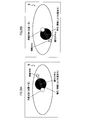
- FIGS. 28A and 28B show examples of image analysis.
- FIGS. 28A and 28B are schematic views showing examples of imaging of the driver's eyes.
- the line of sight (pupil position) is different.
- the pupil is darker in the eye than other parts, and the corneal reflection is brighter in the eye than other parts.
- the pupil and corneal reflection are detected and the positional relationship between them is analyzed using this feature.
- the corneal reflection appears at the most prominent part of the entire cornea and the position thereof is almost constant, and the direction of the line of sight is detected (estimated) from the positional relationship of the pupil with respect to the position of the corneal reflection.
- the direction of the line of sight may be estimated based on the direction connecting the center position of corneal reflection and the center position of the pupil.
- the direction of the line of sight may be estimated based on research data on the relationship between the position of corneal reflection, the position of the pupil, and the direction of the line of sight, past learning values, and the like.
- driving support processing (2) executed by the driving support device 101 will be described with reference to FIG.
- control ECU 20 indirectly determines whether or not the driver has recognized the warning image based on the detection result of the line-of-sight detection unit 10, and reconstructs the warning image based on the determination result ( Correction).
- the display correction process in S602 is a process in which the control ECU 20 corrects the display image based on the result of the correction determination process in S600.
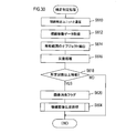
- the correction determination process will be specifically described with reference to FIG.
- control ECU 20 When the control ECU 20 starts the correction determination process of S600 (the correction determination process of FIG. 30), first, the control ECU 20 communicates with the line-of-sight detection unit 10 in S610. Next, the process proceeds to S612, and analysis data by the line-of-sight detection unit 10 (in other words, data indicating movement of the line of sight) is acquired.
- the process of S504 is the same as the process of S504 in FIG. In the emphasized image generation process of S504 in FIG. 30, except for the object (person) for which the flag for erasing the image to be emphasized is set, the other objects (persons) are newly processed in S520 to S524 (FIG. 15). ).
- an object (person) belonging to a group with a lower alert level is moved up to a group with a higher alert level, and an image with a higher alert level can be set.
- S634 it is determined whether or not the image display mode has been reset. In other words, it is determined whether or not the process of S504 in FIG. 30 has been executed. If it is determined in S634 that the image display mode has been reset (the process in S504 has been re-executed), the process proceeds to S636.
- a signal representing an image to be displayed is transmitted to the HUD 7 based on the processing result of S504 in FIG. Thereby, the image is superimposed and displayed on the front window of the vehicle via the HUD 7. Thereafter, the process ends.
- the driving support apparatus 101 displays an image that emphasizes objects around the vehicle in a superimposed manner on the front window, and determines whether the driver of the vehicle has recognized the image. Judgment is made by detecting the driver's line of sight. Then, the display of the image for which the determination result that the driver of the vehicle recognizes is obtained is stopped (in other words, deleted). Then, the display mode is reset. Thereby, another image (an image for emphasizing another object (person)) is further emphasized and displayed. In addition, an object (person) for which an image has not been set can be newly set and emphasized.
- the line-of-sight detection unit 10 corresponds to an example of a line-of-sight detection unit
- the process of S618 corresponds to an example of an identification unit
- the processes of S620 and S602 correspond to an example of an erasure unit.
- ⁇ Fourth embodiment> A fourth embodiment of the present invention will be described.
- the configuration of the driving support device is the same as the configuration of the driving support device 1 of the first embodiment (see FIG. 2).
- the fourth embodiment is different in that the recognition determination process (2) in FIG. 32 is executed instead of the recognition determination process in FIG.
- the recognition determination process (2) in FIG. 32 is different from the recognition determination process in FIG. 13 in that the processes of S650 to S658 are executed. Note that the processing of S400 to S408 is the same as the recognition determination processing of FIG.
- an alarm process for issuing an alarm to the object (person) is executed. Specifically, a process of emitting a predetermined sound (including sound) from the speaker unit 8 is executed. The alarm is issued to make the object (person) aware of the existence of the own vehicle. Also, it is issued to determine whether or not the object (person) has noticed the existence of the own vehicle. Note that an alarm may be given by turning on or blinking the headlamp of the vehicle.
- the process proceeds to S652, and the image data of the infrared camera 4 or the visible light camera 5 is acquired again.
- the face area of the same object (person) is re-extracted based on the image data reacquired in S652.
- step S656 the process proceeds to S656, and the extracted face is analyzed. More specifically, “eyes” are extracted by edge detection and pattern matching. In step S658, it is determined whether both eyes have been detected.
- the driving support device 1 issues an alarm to make the presence of the own vehicle noticeable.
- an object (person) can be made to recognize presence of the own vehicle.
- the danger (warning level) can be set appropriately in accordance with the state of the object (person). As a result, it is possible to display an image for warning the driver more appropriately.
- a fifth embodiment of the present invention will be described.
- the configuration of the driving support device is the same as the configuration of the driving support device 1 of the first embodiment (see FIG. 2).
- the fifth embodiment is different from the driving support device 1 of the first embodiment in that the analysis process 9 of FIG. 33 is further executed.
- the analysis process 9 will be specifically described.
- the processes of S400 to S404 in the analysis process 9 are the same as the processes of S400 to S404 in FIG. 13 (and the processes of S400 to S404 in FIG. 32). Further, the processing of S650 to S658 in the analysis processing 9 is the same as the processing of S650 to S658 in FIG. Description of these processes is omitted.
- the control ECU 8 executes the analysis process 9 in addition to the analysis processes 1 to 7 shown in FIGS. 5 to 12 (and FIG. 13) as the analysis process of S152 in FIG. 4, and in the analysis process 9, in S404 or S658 If it is determined that both eyes have been detected, the process proceeds to S660.
- the alert level is decremented by 2 points for the target object (person) determined to have detected both eyes.
- the numerical value of 2 points is an example, and any value may be used.
- the purpose of the process of S660 is that the object (person) can determine that the object (person) recognizes (or has noticed) the existence of the own vehicle by an affirmative determination in S404 or S658.
- the purpose is to lower.
- the warning level is lowered for the object (person) that recognizes the existence of the own vehicle, and thereby the other object (person) (for example, the existence of the own vehicle is recognized).
- the level of vigilance for objects (persons) that do not exist is relatively increased.
- a more emphasized image can be displayed for an object (person) to be more careful. Therefore, the presence of the object can be recognized more effectively or efficiently by the driver.
- Modification 1 will be described with reference to FIG. 34, the objects H7 and H8 are extracted and recognized.
- the moving direction of the object is detected and displayed by arrows (arrows Y7 and Y8).
- the positions and paths of the objects H7 and H8 after a predetermined time are estimated and displayed.
- the position surrounded by the frame W7 is the current position, and this is the initial position at time tA.
- the driving assistance apparatus 1 repeats acquisition and analysis of the image data of the infrared camera 4 or the visible light camera 5, and executes a tracking process for tracking the movement of the object H7. Then, based on the tracking process, the moving speed and moving direction of the object H7 are estimated.
- the position and speed of the object H7 after a predetermined time tB are estimated, and an image of the object H7 is displayed so as to be superimposed on the estimated position. This image is displayed blinking.
- the position and speed of the object H7 after a predetermined time tC are estimated using the time tA as a reference, and an image of the object H7 is displayed so as to be superimposed on the estimated position. This image is displayed blinking.
- the image after the predetermined time tB and the image after the predetermined time tC are continuously displayed as if the object H7 is moving.
- a movement estimation arrow YF7 is displayed so as to follow a locus from the initial position at time tA to a position after a predetermined time tC.
- the movement estimation arrow YF7 is a movement path of the object H7 and indicates a movement path that is predicted (or is determined to have a high possibility of movement).
- the position surrounded by the frame W8 is the current position, and this is the initial position at time ta.
- the position and speed of the object H8 after a predetermined time tb are estimated, and an image of the object H8 is displayed so as to be superimposed on the estimated position. This image is displayed blinking.
- the position and speed of the object H8 after a predetermined time tc are estimated using the time ta as a reference, and an image of the object H8 is displayed so as to be superimposed on the estimated position. This image is displayed blinking.
- the image after the predetermined time tb and the image after the predetermined time tc are continuously displayed as if the object H8 is moving.
- the object H8 is approaching the host vehicle, and the image of the object H8 is displayed so as to gradually increase.
- a movement estimation arrow YF8 is displayed so as to follow the locus from the initial position at time ta to the position after a predetermined time tc.
- the movement estimation arrow YF8 indicates a movement path of the object H8 and is predicted (or determined to have a high possibility of movement).
- Modification 2 will be described with reference to FIG.
- the driving support apparatus 1 is mounted on a vehicle K3.
- the vehicle K4 is another vehicle.
- the vehicles K3 and K4 are traveling in the same traveling direction (from the bottom to the top (from the front to the back) in the drawing).
- the driving support device 1 of the vehicle K3 analyzes the positional relationship between the objects H12, H13 and the vehicle K4 and determines that the objects H12, H13 are difficult to visually recognize from the vehicle K3, the driving support device 1 in the vehicle Sc3, for example, in a region Sc2 in the rear window. Images of the objects H12 and H13 may be displayed. At this time, an image, a message, or the like that alerts the driver of the vehicle K4 may be displayed.
- FIG. 17 an example in which an image for emphasis is displayed for a person and a vehicle has been described.
- the example of FIG. 36 shows an example of displaying an image for emphasis on other objects around the vehicle in addition to the person and the vehicle. In addition, the name of the object is displayed.
- the driving support device 1 includes the infrared radar 2, the millimeter wave radar 3, the infrared camera 4, and the visible light camera 5 has been described.
- the infrared radar 2 may be omitted and the millimeter wave radar 3 may be configured to detect near and far objects.
- the driving support device 1 includes the infrared radar 2, the millimeter wave radar 3, the infrared camera 4, and the visible light camera 5 has been described.
- the mounting of the infrared radar 2 and the millimeter wave radar 3 may be omitted.
- information detected by each of the infrared camera and the visible light camera information on the distance to the object may be used.
- the driving support device 1 may include a laser radar instead of the millimeter wave radar 3.
- a millimeter wave radar and a laser radar may be provided.
- the laser radar is a radar that detects a surrounding situation using laser light. Specifically, the laser radar scans the pulsed laser beam (two-dimensional scanning), and receives the laser beam that is reflected by the object and returned. Then, the laser radar measures the time difference between the emission time of the laser light and the reception time of the reflected light, and the intensity of the reflected light, and detects an object based on them.
- the laser radar in addition to a three-dimensional object, it is possible to detect a lane boundary line (a white line that forms a boundary such as a vehicle lane and a sidewalk).
- the driving support devices 1, 100, 101 include the infrared radar 2, the millimeter wave radar 3, the infrared camera 4, the visible light camera 5, the momentum detection unit 6, the head-up display 7, the speaker. All of the unit 8, the image projection device 9, and the line-of-sight detection unit 10 may be mounted.
- an example of displaying an image for emphasizing an object has been described, but an image of the object itself may be generated and displayed.
- the infrared cameras 4A and 4B or the visible light cameras 5A and 5B may be used to generate a stereoscopic image by capturing the object stereoscopically and display the stereoscopic image.
- an illuminance sensor may be further provided, and the infrared camera 4 and the visible light camera 5 may be switched and used in accordance with detection data of the illuminance sensor. Specifically, when the illuminance is equal to or higher than a predetermined threshold (for example, during the day), the image data of the visible light camera 5 is used, and when the illuminance is lower than the predetermined threshold (for example, from evening to night, cloudy or rainy) In this case, the data of the infrared camera 4 may be used.
- a predetermined threshold for example, during the day
- the predetermined threshold for example, from evening to night, cloudy or rainy
- whether or not an object (person) is operating a mobile terminal may be determined by communicating with the mobile terminal.
- Bluetooth (registered trademark) equipment or the like is mounted, and pairing with mobile terminals around the vehicle is attempted.
- data communication may be performed with the mobile terminal, and data for determining whether or not the mobile terminal is operated may be acquired from the mobile terminal.
- an application that detects that a user of the mobile terminal is moving and using the mobile terminal is installed on the mobile terminal, the mobile terminal is operated in conjunction with the application. May be detected.
- a warning image may be transmitted from the driving support devices 1, 100, 101 to the mobile terminal, and the image may be displayed on the mobile terminal so that the user of the mobile terminal can recognize the presence of the vehicle.
- the analysis processes 1 to 9 have been described.
- the example in which the analysis processes 1 to 9 are sequentially executed in parallel or in a predetermined order has been described.
- display data is generated based on the result of the analysis process (the process of FIG. 14 is executed), and then the next analysis process is executed.
- Display data may be newly generated based on the result of the analysis process (in other words, display data may be generated (corrected) every time the analysis process is executed).
- the inter-vehicle communication unit may communicate with another vehicle to warn the driver of the other vehicle. Or you may make it receive warning information from another vehicle.
- the position of the own vehicle may be acquired via the vehicle position sensor 12, and based on the acquired position, you may make it grasp
- the analysis processes 1 to 9 FIGGS. 5 to 12 (and FIG. 13), FIG. 24, and FIG. 33
- the analysis process 10 will be described with reference to FIG.
- the analysis process 10 is a process for analyzing the weather, and more specifically, a process for detecting rainy weather.
- the analysis process 10 can be repeatedly executed by the control ECU 20 at a predetermined timing.
- image data of an image captured by the visible light camera 5 is acquired.
- the visible light camera 5 is provided in the vehicle so as to take an image of the surroundings of the vehicle from inside the vehicle through the window glass of the vehicle (see FIG. 1).
- the image data including the image of the area of the window glass of the vehicle is acquired as the image data of the image captured by the visible light camera 5.
- FIG. 38A shows an example of an image of raindrops.
- the raindrop portion becomes blurred and is detected with a transparency different from the transparency of the windowglass portion.
- the portion there appears a portion (edge) where the change in chromaticity (density) of adjacent pixels is steep. Based on such an edge, a raindrop region is detected.
- a raindrop image model is stored in advance in a storage device.
- a storage device a ROM 20b, a flash memory 20d, and the like can be considered, but other storage devices may be used.
- FIG. 38B shows models 1, 2, 3,... N as examples of raindrop image models stored in advance in the storage device.
- models 1, 2, 3,..., N representative models representing raindrops can be arbitrarily selected and stored.
- the control ECU 20 may be provided with a function (learning function) for accumulating a raindrop image model.
- the raindrop candidate detected in S672 is compared with the models 1, 2, 3,... N stored in the storage device, and the area (number of pixels), color between the raindrop candidate and the model is compared.
- the degree of similarity is calculated for parameters such as degree (shading) and shape.
- at least one of the parameters may be used.
- the raindrop candidate may be determined to be a raindrop if the at least one parameter matches a predetermined ratio.
- processing in S672 and S674 can be executed for all raindrop candidates in the image data acquired in S670.
- a predetermined area may be extracted from the image data, and the processes of S672 and S674 may be executed only for the extracted area.
- the process proceeds to S676, and the amount of raindrops (in other words, the amount of rainfall) is detected.
- the amount of raindrops can be detected from the number of raindrops and / or the ratio of the area occupied by the raindrops in the image.
- the process proceeds to S678, and it is determined whether or not the amount of raindrops is a predetermined amount or more. If it is determined that the amount of raindrops is not equal to or greater than the predetermined amount (less than the predetermined amount), the process is terminated as it is. On the other hand, if it is determined that the raindrop amount is greater than or equal to the predetermined amount, the process proceeds to S680, and the warning level is incremented by one point.
- the weather may be recognized by a process different from the analysis process 10. Specifically, the weather may be recognized by the analysis process 11 shown in FIG.
- weather information is acquired by communication with the outside in S682.
- the driving support devices 1, 100, 101 may be provided with a communication device for connecting to a communication line network (for example, the Internet network).
- a communication line network for example, the Internet network.
- the driving assistance apparatus 1,100,101 should just connect to an internet network through the communication apparatus, for example, and should acquire weather information.
- illuminance data is acquired from an illuminance sensor (not shown) for detecting illuminance (outdoor illuminance) included in the vehicle.
- process proceeds to S686, where temperature data is acquired from a temperature sensor (not shown) for detecting an external temperature provided in the vehicle.
- the process proceeds to S688, and it is comprehensively determined whether or not it is rainy based on the data acquired in S682 to S686.
- it can be said that it is possible to grasp the weather only by the processing of S682 (for example, it is possible by acquiring weather forecast information), it is not guaranteed that the weather forecast is 100% accurate, Often, weather forecasts are not made for pinpoint areas.
- an illuminance sensor and a temperature sensor are used, and in addition to weather forecast data, outdoor illuminance and temperature are detected and used to determine whether it is rainy or not, thereby detecting the weather more accurately. be able to.
- the humidity may be detected and used.
- the process proceeds to S690, and it is determined whether the weather is clear based on the processes of S682 to S688. If it is determined to be clear, the process proceeds to S694. In S694, the alert level is maintained at the current alert level (in other words, the process for changing the alert level is not executed). Thereafter, the process is terminated.
- S690 If it is determined in S690 that the weather is not clear, the process proceeds to S692. In S692, it is determined whether or not the weather is cloudy. If it is determined that it is cloudy, then the flow shifts to S696. In S696, the alert level is incremented by one point. Thereafter, the process is terminated.
- the process proceeds to S698, and the warning level is incremented by 2 points.
- the weather can be detected (or determined) with higher accuracy as described above, and thus more appropriate driving support according to the weather can be realized.
- the warning level can be set appropriately according to the weather, the objects around the vehicle are highlighted according to the appropriately set warning level, and / or according to the danger It is possible to appropriately control the warning display.
- the driving support devices 1, 100, 101 of the present embodiment may execute the analysis process 12 in addition to the analysis processes 1 to 11 or instead of the analysis processes 1 to 11.
- the analysis process 12 detects that the user is operating the mobile communication terminal while moving (for example, walking) in conjunction with a function on the mobile communication terminal side such as a smartphone, a tablet, or a mobile phone (more specifically, Is a process of detecting such a portable communication terminal.
- a function and application for detecting that the user is operating the mobile communication terminal while moving may be provided on the mobile communication terminal side. Specifically, it is detected whether the position of the mobile communication terminal is fluctuated by the GPS function or the like, and thus whether the user is moving. And it is detected whether the portable communication terminal or the portable communication terminal is operated when the user is moving.
- a warning to that effect is issued.
- a warning is displayed on the display screen of the mobile communication terminal, a sound is generated, or an alarm (a sound alarm or a signal indicating a warning) is issued to surrounding terminals.
- the analysis process 12 is based on the premise that the mobile communication terminal has the functions and applications as described above.
- S700 a process for searching for portable communication terminals existing around is executed.
- this search it is possible to search by detecting a Bluetooth (registered trademark) signal or other wireless signal emitted from the mobile communication terminal.
- a pairing signal for pairing with Bluetooth (registered trademark) is transmitted from the driving support devices 1, 100, 101, and the presence or absence of a response signal to the pairing signal is detected.
- the presence / absence of a pairing signal transmitted from the mobile communication terminal is detected.
- the mobile communication terminal may be detected by image processing using image data from the visible light camera 5.
- the process proceeds to S702, and based on the process of S700, it is determined whether or not there is a mobile communication terminal around the driving support devices 1, 100, 101. If it is determined that there is no portable communication terminal, the process is terminated as it is. On the other hand, if it is determined that a mobile communication terminal exists, the process proceeds to S704.
- a warning signal warning that the user is operating the mobile communication terminal while moving is received from the mobile communication terminal detected in S700 and 702.
- the specification of this type of warning signal is determined so that it can be detected unconditionally in surrounding communication devices.
- Bluetooth registered trademark
- step S704 If it is determined in S704 that a warning signal has not been received, the processing is terminated as it is. On the other hand, if it is determined that a warning signal has been received, the process proceeds to S706, where a warning is displayed on the HUD 7. In step S708, the alert level is incremented by one point. Thereafter, the process is terminated.
- the driving support devices 1, 100, 101 of this example may control the operation of the vehicle according to the alert level. Such an example will be described with reference to FIGS. 41A and 41B.
- the driving assistance devices 1, 100, and 101 repeatedly execute the vehicle control process of FIG. 41A at a predetermined timing.
- this vehicle control process first, in S710, it is determined whether the alert level is equal to or higher than a predetermined level. If it is determined that the alert level is not equal to or higher than the predetermined level, the process is terminated as it is.
- the process proceeds to S712, and a control command for controlling the vehicle is output.
- this control command can be output to an electronic control unit (ECU) that controls each part of the vehicle. And ECU which received the control command controls a controlled object. After the process of S712, the process is terminated.
- ECU electronice control unit
- Examples of the vehicle control by the vehicle control process include throttle control for controlling the opening of the throttle valve, braking control for controlling a braking device (brake), steering control for controlling the traveling route or traveling direction of the vehicle, and the like. be able to.
- the throttle control may be control that suppresses the throttle opening (in other words, prohibits acceleration).
- the braking control may be control that causes the vehicle to decelerate by causing the brake to function.
- the steering control may be a control for controlling the traveling path of the host vehicle so that the host vehicle is separated from the target object around the host vehicle and the possibility of a collision.
- an alarm may be given.
- a vibration mechanism may be incorporated in the handle, and the vibration mechanism may be vibrated according to a warning level, and an alarm may be transmitted to the driver by vibration (hereinafter, this type of alarm is also referred to as alarm control).
- the driving assistance apparatus 1,100,101 has the table information which matched the warning level and the content of vehicle control as shown to FIG. 41B.
- This table information can be stored in advance in a storage device (ROM 20b or the like).
- vehicle control is realized as follows.
- vehicle control is not executed.
- the value of the warning level is 1 to 3
- warning control and throttle control are performed.
- the value of the warning level is 4 to 6, alarm control, throttle control, and braking control are performed.
- the classification of the alert level is an example.
- the warning level classification may be further subdivided in multiple stages or conversely.
- the variation in the alert level may vary depending on the type of analysis processing to be executed (in this example, analysis processing 1 to 12 is exemplified)
- the table information is optimal depending on the type of analysis processing to be executed. It can be understood by those skilled in the art that it can be realized.
- the display mode is controlled in accordance with the warning level, so that the driver of the vehicle is alerted and the driver can be encouraged to drive safely.
- Vehicle control is executed in order to realize safe driving without the driver's judgment entering the judgment process 101.
- FIGS. 42A and 42B show an example of controlling the display contrast in accordance with the alert level.
- the contrast is intended to be a contrast between a target object (person, obstacle, etc.) to be highlighted and a display object other than the target object.
- the warning level may be associated with the contrast level at the time of display.
- This information can be stored in a storage device (ROM 20b or the like) as table information.
- the driving assistance devices 1, 100, 101 read the information of the table D4 from the storage device, and read the contrast information corresponding to the set alert level. Contrast (contrast ratio) is low when the warning level is-(minus) to 0, medium when the warning level is 1 to 3, high when the warning level is 4 to 6, and when the warning level is 7 or higher May be set to the highest.
- FIG. 42A shows an example when the contrast is low.
- FIG. 42B shows the case where the contrast is highest.
- the contrast between the object D0 as the highlight target and the surroundings (background, etc.) is low, and the difference in brightness between the object D0 and the surroundings is small, but the warning level is low.
- priority may be given to the merit of reducing the contrast.
- the advantages of reducing the contrast may be that eye fatigue may be suppressed in some cases, and that naturalness may be prioritized and may be close to the actual scenery.
- the contrast between the object D0 and its surroundings is high, and the difference in brightness between the object D0 and its surroundings is large. For this reason, the object D0 is more emphasized and can be visually recognized more clearly and clearly.
- the alert level is high, the object D0 may be more emphasized by setting the contrast high in this way.
- shading may be set for each representative region in the image. This point will be described using the tables D3 and D3 ′.
- Tables D3 and D3 ′ contain information on the shades set for each of the representative regions in the image.
- the blocks Da and Da ′ indicate the density of the area of the object D0
- the blocks Db and Db ′ indicate the intensity of the background planting area of the object D0
- the blocks Dc and Dc ′ Indicates the density of the ground surface of the background of the object D0
- the blocks Dd and Dd ′ indicate the density of the road.
- the relative relationship between the shades of the blocks may be automatically set according to the default value according to the contrast level (low, medium, high, maximum).
- the relative relationship between the shades of each block may be set manually by the user (driver).
- a menu display D2 may be provided, and when the menu display D2 is selected, the screen shifts to various setting screens, and the contrast can be set on such a setting screen.
- the display mode can be optimized for each individual user (driver), and the effect of driving support can be maximized.
- the display mode is adjusted according to the skill of the user (driver) (whether or not he is a good driver), age, gender, accident history, violation history, physical ability (mainly visual acuity), physical condition during driving, etc. May be.
- a mechanism for reading a driver's license may be provided, and some of the above information may be automatically acquired by reading the driver's license.
- Information that cannot be read from the driver's license, such as visual acuity and physical condition during driving, may be configured to be manually input.
- a display D1 is a display for indicating that the display control is functioning normally. If any abnormality is detected in the display control, the display content of the display D1 is changed to the content indicating that an abnormality has occurred.
- the target object is highlighted.
- a highlighting mode the frame is surrounded by a frame, highlighted, changed in display color, blinked, and adjacent symbols are displayed.
- Various modes are prepared, and such highlighting may be canceled. That is, the display mode can change in real time.
- the user by providing a display for indicating that the display control is functioning normally like the display D1, the user (driver) can be confident that the displayed screen is a normal screen.
- the user can recognize that fact, and the occurrence of misidentification due to the apologyd display can be suppressed.
- Timing at which the vehicle ignition switch is turned on (2) Timing at which the vehicle actually starts running after the vehicle ignition switch is turned on (for example, timing at which tire rotation is detected) (3) Timing at which the vehicle stopped once after traveling (timing when the vehicle stopped at a signal, crossing store, etc.) (4) Arbitrary timing during traveling of the vehicle (including repeated execution)
- the above timings (1) and (2) are timings when the driving is just started, and the abnormality detection processing is executed at such timing, so that the display D1 is displayed, so that the user (driver) ) Can give a sense of security to future driving.
- the processing load for display control is small, or the processing load for display control is omitted by deliberately omitting the display control. You can do that. If the abnormality detection process is executed at such timing, it is possible to suppress an excessive increase in processing load. In addition, it is possible to suppress the risk that display control, for example, causes any abnormality due to an increase in processing load (for example, risk that processing delay occurs). For this reason, it can contribute to driving support with high safety and reliability.
- the timing of the above (4) is the timing during traveling, and unless the display control is hindered from the viewpoint of processing load or the like, the presence or absence of abnormality can be notified to the user (driver) in real time. It is safer for the driver.
- the display D1 may be always displayed or may be displayed at an arbitrary timing.
- the display timing may be set in accordance with the execution timing of the abnormality detection process as exemplified in the above (1) to (4).
- the display D1 may be displayed in synchronization with the timing at which the abnormality detection process is executed (the timing at which the process is completed).
- FIG. 43 is an example in which a dangerous area in an area (a road or the like) where the vehicle travels is highlighted.
- This example is an example in the case where a landslide disaster occurs and a part of the road is cut off by landslides.
- the driving support devices 1, 100, 101 include the visible light camera 5 as described above, and as described above, the detection target reflected in the image obtained by performing image processing on the image captured by the visible light camera 5, or the detection target An area occupied by the detection target can be recognized. Therefore, the driving assistance devices 1, 100, and 101 may be configured to detect a landslide area and display the emphasis display D6 in a superimposed manner on the landslide area.
- a text display D5 may be displayed adjacent to the highlight display D6. These text display D5 and highlight display D6 may be displayed blinking. Further, the display color may be changed. For example, the display mode may be changed according to the scale of the disaster.
- areas other than the areas where landslides may occur may be additionally highlighted.
- an area where no landslide countermeasure is taken for example, an area not covered with concrete
- an area where water and / or a slight amount of earth and sand, etc. are flowing on the surface is detected by image processing, and the area is detected. May be highlighted.
- FIG. 44 assumes a scene in which a river is running along a river.
- an example of displaying the safety level or risk level of a river level (in other words, the risk of flooding a river) is displayed. It is.
- the water level of a river may be detected and the degree of danger displayed as an indicator.
- an indicator display D10 may be provided.
- a gradation display may be adopted as the indicator display D10.
- a danger display D12 and a safety display D13 can be provided in the vicinity of the indicator display D10. And according to the water level of a river, the present water level frame D14 is superimposed and displayed on the indicator display D10. The closer the display position of the current water level frame D14 is to the danger display D12, the higher the river water level is, and the more dangerous it is. The closer the display position of the current water level frame D14 is to the safety display D13, the safer the display is.
- the text display D11 is provided adjacent to the current water level frame D14. As the text display D11, the degree of danger (or safety) may be displayed as text. Emphasis display D15 can be superimposed and displayed on the area occupied by the river.
- the display mode such as the display color and pattern of the highlight display D15 is preferably matched with the display mode such as the display color and pattern of the region surrounded by the current water level frame D14.
- control ECU 20 of the driving assistance apparatus 1, 100, 101 extracts the data of the display mode in the region surrounded by the current water level frame D14, and then applies the display mode to the display mode of the highlight display D15. Processing will be executed.
- the user can recognize the possibility of the occurrence of the disaster rather than recognizing the fact of the disaster as illustrated in FIG.
- the user (driver) can intuitively grasp the danger level through the indicator display D10 indicating the danger level.
- the display mode of the highlight display D15 matches the display mode of the indicator D10 (the display mode of the region currently surrounded by the water level frame D14), the ease of recognition for the user (driver) is significantly improved. obtain.
- FIG. 45A one of the meanings is to display a target object in three dimensions.
- structures D20 and D22 are buildings that exist along the road on which the host vehicle travels. About this kind of building, you may display in three dimensions using a three-dimensional display technique.
- a stereoscopic display technique a plurality of projectors (generally a pair of left and right projectors) that project from different directions are prepared, and a stereoscopic vision is realized by displaying a left-eye image and a right-eye image, respectively. It has been known.
- map data including stereoscopic image data may be used. That is, an image represented by the stereoscopic image data may be displayed. According to the three-dimensional display, it is expected that the user (driver) can more easily see.
- symbol displays D21 and D23 are drawn in accordance with the attributes of the structures D20 and D22, respectively.
- the attribute includes the type of structure. Types of structures include stores, government offices, and private houses.
- the attribute includes attached information attached to the structure.
- the attached information includes information such as business hours, store size, average number of visitors, and location information.
- Such attribute information is attached to the map data, for example, and the driving support device 1, 100, 101 side may be obtained from the map data.
- the structure D20 is a convenience store, for example, information such as being a store, being open 24 hours, and having many visitors in the morning and evening is included in the attributes of the structure D20. obtain.
- the control ECU 20 displays a symbol display D21 that calls attention to the presence or absence of vehicles from the parking lot on the basis of information indicating that there are many visitors 24 hours a day, and the structure D20.
- Display in association with Displaying in association with the structure D20 is understood to mean, for example, displaying near the structure D20, displaying adjacent to the structure D20, or displaying superimposed on the structure D20. Also good.
- the structure D22 is located at a point where the road is curved, and information (location information) that “is located at a curve point” is included in the attribute. For example, based on such attributes, the control ECU 20 displays a symbol display D23 that prompts traveling along a curve in association with the structure D22.
- FIG. 45B shows an example in which the oncoming vehicle is running outside the central lane.
- the control ECU 20 estimates a route on which the oncoming vehicle may travel by calculation, and displays the emphasis display D25 superimposed on the estimated area.
- display control may not be performed when the oncoming vehicle is traveling in the lane.
- display control may be executed when an oncoming vehicle is running out of the lane and there is a risk of collision.
- FIG. 45C shows an example in which the host vehicle is running outside the lane.
- the control ECU 20 estimates a route on which the host vehicle may travel by calculation, displays a symbol of the host vehicle, and displays a highlight display D27 in a superimposed manner on the estimated region.
- Such display control may not be performed when the host vehicle is traveling in a lane.
- such display control may be executed when the host vehicle is running out of the lane and there is a risk of collision.
- the display mode of the highlight display D25 and the display mode of the highlight display D27 are different in an easily distinguishable form. In this case, it is easy to recognize whether the oncoming vehicle protrudes from the lane and is dangerous, or whether the host vehicle protrudes from the lane and is dangerous.
- the display screen may be configured with a touch panel. Then, by selecting an object on the touch panel, the object may be highlighted or canceled.
- the warning level may be additionally increased (a point of the warning level is additionally incremented).
Landscapes
- Physics & Mathematics (AREA)
- Engineering & Computer Science (AREA)
- General Physics & Mathematics (AREA)
- Multimedia (AREA)
- Theoretical Computer Science (AREA)
- Traffic Control Systems (AREA)
- Control Of Driving Devices And Active Controlling Of Vehicle (AREA)
- Instrument Panels (AREA)
- Image Analysis (AREA)
Abstract
La présente invention concerne un dispositif d'aide à la conduite comprenant : des moyens de détection qui détectent des conditions autour d'un véhicule ; des moyens de reconnaissance qui reconnaissent des objets autour du véhicule sur la base du résultat de détection des moyens de détection ; des moyens d'analyse qui analysent les objets reconnus par les moyens de reconnaissance ; des moyens de détermination qui déterminent, sur la base du résultat de l'analyse des moyens d'analyse, des degrés de précaution à adopter par rapport aux objets ; des moyens de génération qui génèrent, sur la base des degrés déterminés par les moyens de détermination, une image permettant à un conducteur de reconnaître visuellement les objets ; et des moyens d'affichage qui affichent l'image générée par les moyens de génération.
Priority Applications (1)
| Application Number | Priority Date | Filing Date | Title |
|---|---|---|---|
| JP2016511968A JP6598255B2 (ja) | 2014-03-31 | 2015-03-31 | 運転支援装置、及び運転支援システム |
Applications Claiming Priority (2)
| Application Number | Priority Date | Filing Date | Title |
|---|---|---|---|
| JP2014-072419 | 2014-03-31 | ||
| JP2014072419 | 2014-03-31 |
Publications (1)
| Publication Number | Publication Date |
|---|---|
| WO2015152304A1 true WO2015152304A1 (fr) | 2015-10-08 |
Family
ID=54240622
Family Applications (1)
| Application Number | Title | Priority Date | Filing Date |
|---|---|---|---|
| PCT/JP2015/060272 Ceased WO2015152304A1 (fr) | 2014-03-31 | 2015-03-31 | Dispositif d'aide à la conduite et procédé d'aide à la conduite |
Country Status (2)
| Country | Link |
|---|---|
| JP (3) | JP6598255B2 (fr) |
| WO (1) | WO2015152304A1 (fr) |
Cited By (29)
| Publication number | Priority date | Publication date | Assignee | Title |
|---|---|---|---|---|
| JP2016147652A (ja) * | 2015-02-09 | 2016-08-18 | 株式会社デンソー | 車両用表示制御装置及び車両用表示ユニット |
| JP2017224067A (ja) * | 2016-06-14 | 2017-12-21 | 大学共同利用機関法人自然科学研究機構 | わき見状態判定装置 |
| JP2018025898A (ja) * | 2016-08-09 | 2018-02-15 | 日立オートモティブシステムズ株式会社 | 表示内容認識装置、および車両制御装置 |
| US20180137601A1 (en) * | 2016-11-15 | 2018-05-17 | Kazuhiro Takazawa | Display apparatus, display system, and display control method |
| CN108290499A (zh) * | 2015-11-24 | 2018-07-17 | 康蒂-特米克微电子有限公司 | 带有自适应周围环境图像数据处理功能的驾驶员辅助系统 |
| KR20180132922A (ko) * | 2016-05-30 | 2018-12-12 | 엘지전자 주식회사 | 차량용 디스플레이 장치 및 차량 |
| KR20190031951A (ko) * | 2017-09-19 | 2019-03-27 | 삼성전자주식회사 | 운송 장치에 구비된 전자 장치 및 이의 제어 방법 |
| JP2019109157A (ja) * | 2017-12-19 | 2019-07-04 | ヤフー株式会社 | 推定装置、推定方法および推定プログラム |
| CN110015247A (zh) * | 2017-12-28 | 2019-07-16 | 丰田自动车株式会社 | 显示控制装置和显示控制方法 |
| JP2019155960A (ja) * | 2018-03-07 | 2019-09-19 | 矢崎総業株式会社 | 車両用表示投影装置 |
| DE102019204340A1 (de) | 2018-03-29 | 2019-10-02 | Honda Motor Co., Ltd. | Ausgabevorrichtung |
| WO2019194084A1 (fr) * | 2018-04-04 | 2019-10-10 | パナソニック株式会社 | Système de surveillance de trafic et procédé de surveillance de trafic |
| WO2020058740A1 (fr) * | 2018-09-17 | 2020-03-26 | 日産自動車株式会社 | Procédé de prédiction de comportement de véhicule et dispositif de prédiction de comportement de véhicule |
| WO2020115981A1 (fr) * | 2018-12-03 | 2020-06-11 | 株式会社Jvcケンウッド | Dispositif de traitement de reconnaissance, procédé de traitement de reconnaissance, et programme |
| US10688928B2 (en) | 2016-10-20 | 2020-06-23 | Panasonic Corporation | Pedestrian-vehicle communication system, in-vehicle terminal device, pedestrian terminal device and safe-driving assistance method |
| JP2020112698A (ja) * | 2019-01-11 | 2020-07-27 | 株式会社リコー | 表示制御装置、表示装置、表示システム、移動体、プログラム、画像生成方法 |
| JP2020113185A (ja) * | 2019-01-16 | 2020-07-27 | 株式会社京三製作所 | 交差点警告システム |
| JP6746013B1 (ja) * | 2019-06-19 | 2020-08-26 | 三菱電機株式会社 | ペアリング表示装置、ペアリング表示システムおよびペアリング表示方法 |
| JP2020159424A (ja) * | 2019-03-26 | 2020-10-01 | ダイハツ工業株式会社 | 車両の制御装置 |
| KR20200129361A (ko) * | 2019-05-08 | 2020-11-18 | 주식회사 퀀텀게이트 | 스몸비 교통사고 방지를 위한 볼라드를 구비하는 보행자 교통안전 시스템 및 이의 동작방법 |
| CN112166434A (zh) * | 2018-05-25 | 2021-01-01 | 罗伯特·博世有限公司 | 运行辅助方法、控制单元、运行辅助系统和工作设备 |
| WO2021079975A1 (fr) * | 2019-10-23 | 2021-04-29 | ソニー株式会社 | Système d'affichage, dispositif d'affichage, procédé d'affichage et dispositif en mouvement |
| JP2021086229A (ja) * | 2019-11-25 | 2021-06-03 | パイオニア株式会社 | 表示制御装置、表示制御方法及び表示制御用プログラム |
| US11127297B2 (en) * | 2017-07-17 | 2021-09-21 | Veoneer Us, Inc. | Traffic environment adaptive thresholds |
| JPWO2021234937A1 (fr) * | 2020-05-22 | 2021-11-25 | ||
| WO2022038878A1 (fr) * | 2020-08-21 | 2022-02-24 | Sony Group Corporation | Appareil et procédé d'affichage d'informations, et programme |
| JP2023081590A (ja) * | 2021-12-01 | 2023-06-13 | 株式会社小野測器 | 移動量計測システム |
| WO2023238344A1 (fr) * | 2022-06-09 | 2023-12-14 | 日産自動車株式会社 | Procédé d'aide au stationnement et dispositif d'aide au stationnement |
| US12394240B2 (en) * | 2020-10-07 | 2025-08-19 | Jvckenwood Corporation | Picture recognition apparatus, picture recognition method, and non-transitory program recording medium displaying a generated display picture |
Families Citing this family (7)
| Publication number | Priority date | Publication date | Assignee | Title |
|---|---|---|---|---|
| JP7402083B2 (ja) * | 2020-02-28 | 2023-12-20 | 本田技研工業株式会社 | 表示方法、表示装置及び表示システム |
| JP2022039103A (ja) * | 2020-08-27 | 2022-03-10 | Jrcモビリティ株式会社 | 物標情報表示装置 |
| JP7600767B2 (ja) * | 2021-03-02 | 2024-12-17 | 株式会社Jvcケンウッド | 表示制御装置、表示制御方法及びプログラム |
| JP2022161464A (ja) * | 2021-04-09 | 2022-10-21 | キヤノン株式会社 | 運転支援装置、移動装置、運転支援方法、コンピュータプログラム、及び記憶媒体 |
| JP7613252B2 (ja) * | 2021-05-10 | 2025-01-15 | 株式会社デンソー | 表示制御装置 |
| KR20230061665A (ko) | 2021-10-28 | 2023-05-09 | 주식회사 에이치엘클레무브 | 운전자 보조 시스템 및 운전자 보조 방법 |
| JP7782373B2 (ja) * | 2022-06-10 | 2025-12-09 | トヨタ自動車株式会社 | 車両用表示制御装置、車両用表示システム、車両用表示制御方法及びプログラム |
Citations (6)
| Publication number | Priority date | Publication date | Assignee | Title |
|---|---|---|---|---|
| US20060151223A1 (en) * | 2002-11-16 | 2006-07-13 | Peter Knoll | Device and method for improving visibility in a motor vehicle |
| WO2008029802A1 (fr) * | 2006-09-04 | 2008-03-13 | Panasonic Corporation | Dispositif fournissant des informations de voyage |
| JP2009040108A (ja) * | 2007-08-06 | 2009-02-26 | Denso Corp | 画像表示制御装置及び画像表示制御システム |
| JP2010234851A (ja) * | 2009-03-30 | 2010-10-21 | Mazda Motor Corp | 車両用表示装置 |
| JP2011257984A (ja) * | 2010-06-09 | 2011-12-22 | Toyota Central R&D Labs Inc | 対象物検出装置及びプログラム |
| WO2014034065A1 (fr) * | 2012-08-31 | 2014-03-06 | 株式会社デンソー | Dispositif d'avertissement de corps en mouvement et procédé d'avertissement de corps en mouvement |
Family Cites Families (18)
| Publication number | Priority date | Publication date | Assignee | Title |
|---|---|---|---|---|
| JP2002304700A (ja) * | 2001-04-06 | 2002-10-18 | Honda Motor Co Ltd | 移動体警報システム |
| JP4578795B2 (ja) * | 2003-03-26 | 2010-11-10 | 富士通テン株式会社 | 車両制御装置、車両制御方法および車両制御プログラム |
| JP2006151114A (ja) * | 2004-11-26 | 2006-06-15 | Fujitsu Ten Ltd | 運転支援装置 |
| JP2007148835A (ja) * | 2005-11-28 | 2007-06-14 | Fujitsu Ten Ltd | 物体判別装置、報知制御装置、物体判別方法および物体判別プログラム |
| JP2008310376A (ja) * | 2007-06-12 | 2008-12-25 | Mazda Motor Corp | 歩行者検出装置 |
| JP2009015547A (ja) * | 2007-07-04 | 2009-01-22 | Omron Corp | 運転支援装置および方法、並びに、プログラム |
| JP2009040115A (ja) * | 2007-08-06 | 2009-02-26 | Mazda Motor Corp | 車両用運転支援装置 |
| JP2009226978A (ja) * | 2008-03-19 | 2009-10-08 | Mazda Motor Corp | 車両用周囲監視装置 |
| JP2009251758A (ja) * | 2008-04-02 | 2009-10-29 | Toyota Motor Corp | 歩車間通信装置、携帯端末 |
| US8812226B2 (en) * | 2009-01-26 | 2014-08-19 | GM Global Technology Operations LLC | Multiobject fusion module for collision preparation system |
| JP5407898B2 (ja) * | 2010-01-25 | 2014-02-05 | 株式会社豊田中央研究所 | 対象物検出装置及びプログラム |
| EP2388756B1 (fr) * | 2010-05-17 | 2019-01-09 | Volvo Car Corporation | Réduction du risque de collision frontale |
| KR101410040B1 (ko) * | 2010-12-08 | 2014-06-27 | 주식회사 만도 | 어린이 보행자 보호 장치 및 그의 어린이 보행자 보호 방법 |
| JP2012247326A (ja) * | 2011-05-30 | 2012-12-13 | Sanyo Electric Co Ltd | 歩行経路案内装置及びシステム |
| JP5617819B2 (ja) * | 2011-10-28 | 2014-11-05 | 株式会社デンソー | 歩行者認識装置 |
| JP2013131143A (ja) * | 2011-12-22 | 2013-07-04 | Sanyo Electric Co Ltd | 移動体通信装置及び通信制御方法 |
| JP2013191050A (ja) * | 2012-03-14 | 2013-09-26 | Toyota Motor Corp | 車両周辺監視装置 |
| JP5998777B2 (ja) * | 2012-09-12 | 2016-09-28 | ソニー株式会社 | 情報処理装置と情報処理方法とプログラムおよび情報処理システム |
-
2015
- 2015-03-31 WO PCT/JP2015/060272 patent/WO2015152304A1/fr not_active Ceased
- 2015-03-31 JP JP2016511968A patent/JP6598255B2/ja not_active Expired - Fee Related
-
2018
- 2018-12-25 JP JP2018241012A patent/JP6860763B2/ja active Active
-
2019
- 2019-09-26 JP JP2019175422A patent/JP6919914B2/ja not_active Expired - Fee Related
Patent Citations (6)
| Publication number | Priority date | Publication date | Assignee | Title |
|---|---|---|---|---|
| US20060151223A1 (en) * | 2002-11-16 | 2006-07-13 | Peter Knoll | Device and method for improving visibility in a motor vehicle |
| WO2008029802A1 (fr) * | 2006-09-04 | 2008-03-13 | Panasonic Corporation | Dispositif fournissant des informations de voyage |
| JP2009040108A (ja) * | 2007-08-06 | 2009-02-26 | Denso Corp | 画像表示制御装置及び画像表示制御システム |
| JP2010234851A (ja) * | 2009-03-30 | 2010-10-21 | Mazda Motor Corp | 車両用表示装置 |
| JP2011257984A (ja) * | 2010-06-09 | 2011-12-22 | Toyota Central R&D Labs Inc | 対象物検出装置及びプログラム |
| WO2014034065A1 (fr) * | 2012-08-31 | 2014-03-06 | 株式会社デンソー | Dispositif d'avertissement de corps en mouvement et procédé d'avertissement de corps en mouvement |
Cited By (62)
| Publication number | Priority date | Publication date | Assignee | Title |
|---|---|---|---|---|
| JP2016147652A (ja) * | 2015-02-09 | 2016-08-18 | 株式会社デンソー | 車両用表示制御装置及び車両用表示ユニット |
| CN108290499A (zh) * | 2015-11-24 | 2018-07-17 | 康蒂-特米克微电子有限公司 | 带有自适应周围环境图像数据处理功能的驾驶员辅助系统 |
| JP2019504382A (ja) * | 2015-11-24 | 2019-02-14 | コンティ テミック マイクロエレクトロニック ゲゼルシャフト ミット ベシュレンクテル ハフツングConti Temic microelectronic GmbH | アダプティブな周辺画像データ処理を有するドライバー・アシスタント・システム |
| CN108290499B (zh) * | 2015-11-24 | 2022-01-11 | 康蒂-特米克微电子有限公司 | 带有自适应周围环境图像数据处理功能的驾驶员辅助系统 |
| KR102201290B1 (ko) * | 2016-05-30 | 2021-01-08 | 엘지전자 주식회사 | 차량용 디스플레이 장치 및 차량 |
| KR20180132922A (ko) * | 2016-05-30 | 2018-12-12 | 엘지전자 주식회사 | 차량용 디스플레이 장치 및 차량 |
| US11242068B2 (en) | 2016-05-30 | 2022-02-08 | Lg Electronics Inc. | Vehicle display device and vehicle |
| JP2017224067A (ja) * | 2016-06-14 | 2017-12-21 | 大学共同利用機関法人自然科学研究機構 | わき見状態判定装置 |
| JP2018025898A (ja) * | 2016-08-09 | 2018-02-15 | 日立オートモティブシステムズ株式会社 | 表示内容認識装置、および車両制御装置 |
| WO2018030103A1 (fr) * | 2016-08-09 | 2018-02-15 | 日立オートモティブシステムズ株式会社 | Dispositif de reconnaissance de contenu affiché et dispositif de commande de véhicule |
| US10688928B2 (en) | 2016-10-20 | 2020-06-23 | Panasonic Corporation | Pedestrian-vehicle communication system, in-vehicle terminal device, pedestrian terminal device and safe-driving assistance method |
| US10453176B2 (en) * | 2016-11-15 | 2019-10-22 | Ricoh Company, Ltd. | Display apparatus to control display form of virtual object |
| US20180137601A1 (en) * | 2016-11-15 | 2018-05-17 | Kazuhiro Takazawa | Display apparatus, display system, and display control method |
| US11127297B2 (en) * | 2017-07-17 | 2021-09-21 | Veoneer Us, Inc. | Traffic environment adaptive thresholds |
| KR20190031951A (ko) * | 2017-09-19 | 2019-03-27 | 삼성전자주식회사 | 운송 장치에 구비된 전자 장치 및 이의 제어 방법 |
| KR102436962B1 (ko) * | 2017-09-19 | 2022-08-29 | 삼성전자주식회사 | 운송 장치에 구비된 전자 장치 및 이의 제어 방법 |
| JP2019109157A (ja) * | 2017-12-19 | 2019-07-04 | ヤフー株式会社 | 推定装置、推定方法および推定プログラム |
| CN110015247A (zh) * | 2017-12-28 | 2019-07-16 | 丰田自动车株式会社 | 显示控制装置和显示控制方法 |
| JP2019155960A (ja) * | 2018-03-07 | 2019-09-19 | 矢崎総業株式会社 | 車両用表示投影装置 |
| JP7048358B2 (ja) | 2018-03-07 | 2022-04-05 | 矢崎総業株式会社 | 車両用表示投影装置 |
| CN110319848A (zh) * | 2018-03-29 | 2019-10-11 | 本田技研工业株式会社 | 输出装置 |
| CN110319848B (zh) * | 2018-03-29 | 2023-03-14 | 本田技研工业株式会社 | 输出装置 |
| US10818174B2 (en) | 2018-03-29 | 2020-10-27 | Honda Motor Co., Ltd. | Output apparatus |
| DE102019204340B4 (de) | 2018-03-29 | 2024-03-21 | Honda Motor Co., Ltd. | Ausgabevorrichtung |
| DE102019204340A1 (de) | 2018-03-29 | 2019-10-02 | Honda Motor Co., Ltd. | Ausgabevorrichtung |
| US11869347B2 (en) | 2018-04-04 | 2024-01-09 | Panasonic Holdings Corporation | Traffic monitoring system and traffic monitoring method |
| JP7092540B2 (ja) | 2018-04-04 | 2022-06-28 | パナソニックホールディングス株式会社 | 交通監視システムおよび交通監視方法 |
| JP2019185220A (ja) * | 2018-04-04 | 2019-10-24 | パナソニック株式会社 | 交通監視システムおよび交通監視方法 |
| WO2019194084A1 (fr) * | 2018-04-04 | 2019-10-10 | パナソニック株式会社 | Système de surveillance de trafic et procédé de surveillance de trafic |
| JP7244546B2 (ja) | 2018-05-25 | 2023-03-22 | ロベルト・ボッシュ・ゲゼルシャフト・ミト・ベシュレンクテル・ハフツング | 運転支援方法、制御ユニット、運転支援システム、および操作装置 |
| CN112166434A (zh) * | 2018-05-25 | 2021-01-01 | 罗伯特·博世有限公司 | 运行辅助方法、控制单元、运行辅助系统和工作设备 |
| JP2021525423A (ja) * | 2018-05-25 | 2021-09-24 | ロベルト・ボッシュ・ゲゼルシャフト・ミト・ベシュレンクテル・ハフツングRobert Bosch Gmbh | 運転支援方法、制御ユニット、運転支援システム、および操作装置 |
| US11403854B2 (en) | 2018-05-25 | 2022-08-02 | Robert Bosch Gmbh | Operating assistance method, control unit, operating assistance system and working device |
| WO2020058740A1 (fr) * | 2018-09-17 | 2020-03-26 | 日産自動車株式会社 | Procédé de prédiction de comportement de véhicule et dispositif de prédiction de comportement de véhicule |
| RU2762150C1 (ru) * | 2018-09-17 | 2021-12-16 | Ниссан Мотор Ко., Лтд. | Способ прогнозирования поведения транспортного средства и устройство прогнозирования поведения транспортного средства |
| WO2020115981A1 (fr) * | 2018-12-03 | 2020-06-11 | 株式会社Jvcケンウッド | Dispositif de traitement de reconnaissance, procédé de traitement de reconnaissance, et programme |
| JP2020112698A (ja) * | 2019-01-11 | 2020-07-27 | 株式会社リコー | 表示制御装置、表示装置、表示システム、移動体、プログラム、画像生成方法 |
| US11752940B2 (en) | 2019-01-11 | 2023-09-12 | Ricoh Company, Ltd. | Display controller, display system, mobile object, image generation method, and carrier means |
| JP2020113185A (ja) * | 2019-01-16 | 2020-07-27 | 株式会社京三製作所 | 交差点警告システム |
| JP7240182B2 (ja) | 2019-01-16 | 2023-03-15 | 株式会社京三製作所 | 交差点警告システム |
| JP2020159424A (ja) * | 2019-03-26 | 2020-10-01 | ダイハツ工業株式会社 | 車両の制御装置 |
| KR20200129361A (ko) * | 2019-05-08 | 2020-11-18 | 주식회사 퀀텀게이트 | 스몸비 교통사고 방지를 위한 볼라드를 구비하는 보행자 교통안전 시스템 및 이의 동작방법 |
| KR102237966B1 (ko) * | 2019-05-08 | 2021-04-08 | 주식회사 퀀텀게이트 | 스몸비 교통사고 방지를 위한 볼라드를 구비하는 보행자 교통안전 시스템 및 이의 동작방법 |
| CN113950711B (zh) * | 2019-06-19 | 2023-11-21 | 三菱电机株式会社 | 配对显示装置、配对显示系统以及配对显示方法 |
| WO2020255286A1 (fr) * | 2019-06-19 | 2020-12-24 | 三菱電機株式会社 | Dispositif d'affichage d'appariement, système d'affichage d'appariement et procédé d'affichage d'appariement |
| CN113950711A (zh) * | 2019-06-19 | 2022-01-18 | 三菱电机株式会社 | 配对显示装置、配对显示系统以及配对显示方法 |
| JP6746013B1 (ja) * | 2019-06-19 | 2020-08-26 | 三菱電機株式会社 | ペアリング表示装置、ペアリング表示システムおよびペアリング表示方法 |
| US12522142B2 (en) | 2019-10-23 | 2026-01-13 | Sony Group Corporation | Display system, display device, display method, and mobile apparatus |
| WO2021079975A1 (fr) * | 2019-10-23 | 2021-04-29 | ソニー株式会社 | Système d'affichage, dispositif d'affichage, procédé d'affichage et dispositif en mouvement |
| JP7496683B2 (ja) | 2019-11-25 | 2024-06-07 | パイオニア株式会社 | 表示制御装置、表示制御方法及び表示制御用プログラム |
| JP2021086229A (ja) * | 2019-11-25 | 2021-06-03 | パイオニア株式会社 | 表示制御装置、表示制御方法及び表示制御用プログラム |
| JP7357784B2 (ja) | 2020-05-22 | 2023-10-06 | 三菱電機株式会社 | 警報制御装置及び警報制御方法 |
| JPWO2021234937A1 (fr) * | 2020-05-22 | 2021-11-25 | ||
| WO2022038878A1 (fr) * | 2020-08-21 | 2022-02-24 | Sony Group Corporation | Appareil et procédé d'affichage d'informations, et programme |
| US12394240B2 (en) * | 2020-10-07 | 2025-08-19 | Jvckenwood Corporation | Picture recognition apparatus, picture recognition method, and non-transitory program recording medium displaying a generated display picture |
| JP2023081590A (ja) * | 2021-12-01 | 2023-06-13 | 株式会社小野測器 | 移動量計測システム |
| JP7588575B2 (ja) | 2021-12-01 | 2024-11-22 | 株式会社小野測器 | 移動量計測システム |
| WO2023238344A1 (fr) * | 2022-06-09 | 2023-12-14 | 日産自動車株式会社 | Procédé d'aide au stationnement et dispositif d'aide au stationnement |
| JPWO2023238344A1 (fr) * | 2022-06-09 | 2023-12-14 | ||
| CN119301657A (zh) * | 2022-06-09 | 2025-01-10 | 日产自动车株式会社 | 驻车辅助方法以及驻车辅助装置 |
| US12394181B1 (en) | 2022-06-09 | 2025-08-19 | Nissan Motor Co., Ltd. | Parking assist method and parking assist device |
| JP7747200B2 (ja) | 2022-06-09 | 2025-10-01 | 日産自動車株式会社 | 駐車支援方法及び駐車支援装置 |
Also Published As
| Publication number | Publication date |
|---|---|
| JPWO2015152304A1 (ja) | 2017-04-13 |
| JP2020095688A (ja) | 2020-06-18 |
| JP6598255B2 (ja) | 2019-10-30 |
| JP6860763B2 (ja) | 2021-04-21 |
| JP2019075150A (ja) | 2019-05-16 |
| JP6919914B2 (ja) | 2021-08-18 |
Similar Documents
| Publication | Publication Date | Title |
|---|---|---|
| JP6919914B2 (ja) | 運転支援装置 | |
| JP7332726B2 (ja) | ヒートマップを使用したドライバーの注目の検出 | |
| JP7301138B2 (ja) | ポットホール検出システム | |
| CN102317952B (zh) | 在显示装置的显示器上呈现运输工具周围环境中可见性不同的物体的方法 | |
| CN108082037B (zh) | 制动灯检测 | |
| US11242068B2 (en) | Vehicle display device and vehicle | |
| CN106463060B (zh) | 处理装置、处理系统和处理方法 | |
| KR101359660B1 (ko) | 헤드업 디스플레이를 위한 증강현실 시스템 | |
| US20160185219A1 (en) | Vehicle-mounted display control device | |
| US20180211121A1 (en) | Detecting Vehicles In Low Light Conditions | |
| KR101986734B1 (ko) | 차량 운전 보조 장치 및 이의 안전 운전 유도 방법 | |
| JP7255608B2 (ja) | 表示制御装置、方法、及びコンピュータ・プログラム | |
| JP2016020876A (ja) | 車両用表示装置 | |
| CN108482367A (zh) | 一种基于智能后视镜辅助驾驶的方法、装置及系统 | |
| US20230249614A1 (en) | Method and system for displaying external communication message | |
| JP4872245B2 (ja) | 歩行者認識装置 | |
| JP6555413B2 (ja) | 移動体周囲表示方法及び移動体周囲表示装置 | |
| CN111086518B (zh) | 显示方法、装置、车载平视显示设备及存储介质 | |
| KR20190071781A (ko) | 열에너지 정보를 표시하는 나이트 비젼 시스템 및 그 제어방법 | |
| KR101935853B1 (ko) | 라이다 및 레이더를 이용한 나이트 비전 시스템 | |
| KR20170068936A (ko) | 운전자 시선 기반 영상 출력 및 차량 컨트롤 결정 방법 | |
| JP4701961B2 (ja) | 歩行者検知装置 | |
| JP6337601B2 (ja) | 立体物検出装置 | |
| KR20230020932A (ko) | 스케일링가능하고 사실적인 카메라 폐색 데이터 세트 생성 | |
| US20240192313A1 (en) | Methods and systems for displaying information to an occupant of a vehicle |
Legal Events
| Date | Code | Title | Description |
|---|---|---|---|
| 121 | Ep: the epo has been informed by wipo that ep was designated in this application |
Ref document number: 15774422 Country of ref document: EP Kind code of ref document: A1 |
|
| ENP | Entry into the national phase |
Ref document number: 2016511968 Country of ref document: JP Kind code of ref document: A |
|
| NENP | Non-entry into the national phase | ||
| 122 | Ep: pct application non-entry in european phase |
Ref document number: 15774422 Country of ref document: EP Kind code of ref document: A1 |