WO2015155902A1 - Structure et procédé de ventilation de poulailler - Google Patents
Structure et procédé de ventilation de poulailler Download PDFInfo
- Publication number
- WO2015155902A1 WO2015155902A1 PCT/JP2014/065469 JP2014065469W WO2015155902A1 WO 2015155902 A1 WO2015155902 A1 WO 2015155902A1 JP 2014065469 W JP2014065469 W JP 2014065469W WO 2015155902 A1 WO2015155902 A1 WO 2015155902A1
- Authority
- WO
- WIPO (PCT)
- Prior art keywords
- ventilation
- vent
- poultry house
- air
- wall
- Prior art date
- Legal status (The legal status is an assumption and is not a legal conclusion. Google has not performed a legal analysis and makes no representation as to the accuracy of the status listed.)
- Ceased
Links
Images


Classifications
-
- A—HUMAN NECESSITIES
- A01—AGRICULTURE; FORESTRY; ANIMAL HUSBANDRY; HUNTING; TRAPPING; FISHING
- A01K—ANIMAL HUSBANDRY; AVICULTURE; APICULTURE; PISCICULTURE; FISHING; REARING OR BREEDING ANIMALS, NOT OTHERWISE PROVIDED FOR; NEW BREEDS OF ANIMALS
- A01K1/00—Housing animals; Equipment therefor
- A01K1/0047—Air-conditioning, e.g. ventilation, of animal housings
- A01K1/0064—Construction of air inlets or outlets in walls
Definitions
- the present invention relates to a ventilation structure for a poultry house and a method for ventilating a poultry house using the ventilation structure.
- Patent Document 1 a poultry house equipped with a windless ventilation structure
- Patent Document 2 a poultry house equipped with a windless ventilation structure
- These are poultry houses with long rows of cages, with an inlet on one side of the wife's surface (the side perpendicular to the ridge) and an exhaust outlet on the other side of the wife's surface, each with a large area
- an auxiliary air inlet extending from the approximate center in the longitudinal direction of the side wall toward the wife surface with the air outlet is provided between the roof.
- the inside of the poultry house is made negative pressure by forcibly exhausting with an exhaust fan attached to the exhaust port, and ventilation is performed by taking in air from the intake port or the auxiliary intake port.
- the air taken into the poultry house flows through the poultry house while being heated at the body temperature of the birds, and is discharged from the exhaust port.
- the air intake is switched between the inlet and the auxiliary inlet, or the amount of air taken in is adjusted to adjust the air flow upstream and downstream of the house. And the temperature difference can be reduced.
- a hanging wall 140 that covers the upper part of the side wall 110 from the outside is suspended from the roof 81 by providing a gap between the side wall 110.
- Such a structure using the hanging wall 140 avoids the possibility that sunlight or a strong wind blows into the poultry house through the auxiliary inlet 120 by the hanging wall 140.
- outside air is taken into the poultry house through the air passage 125 and the auxiliary air inlet 120 as shown by arrows in FIG.
- a net 129 is stretched between the vertical wall 140 and the side wall 110 in order to prevent birds and insects from entering the poultry house through the air passage 125.
- an object of the present invention is to provide a ventilation structure for a poultry house that can smoothly ventilate during a power failure, and a method for ventilating a poultry house using the ventilation structure.
- the ventilating structure for a poultry house includes: a vent formed in the upper part of the wall of the poultry house, and the vent when the vent is opened and closed and power supply is stopped.
- Vents formed in the upper part of the wall include vents formed by providing a gap between the upper end of the wall and the roof, and the upper end and ceiling of the wall when the poultry house has a ceiling. An air vent formed by providing a gap between them can be exemplified.
- Examples of the “ventilation adjusting device” include a configuration having a one-way opening / closing plate member that opens and closes the vent by rotation, or a configuration having an opening / closing plate member that opens and closes the vent by sliding. Further, as a mechanism that the ventilation adjustment device “opens the vent when power supply is stopped”, a mechanism that switches the power supply from the battery to drive the opening / closing plate material when the power supply stops, A mechanism that closes the vent with an open / close plate by electromagnetic force against the urging in the direction of opening the vent can be exemplified.
- a space between a plurality of thin plate members arranged side by side is a ventilation space through which air passes.
- the thin plate material blocks light traveling straight by at least one of bending, bending, and tilting, and the light does not pass through the ventilation space.
- the aspect which only curves or bends, the aspect which only inclines, the aspect which inclines while curving or bending can be illustrated.
- “natural passage” of air means that air passes through the ventilation space without forcibly moving the air such as intake air or pressure feeding.
- the vent opening that is opened when power supply is stopped is formed in the upper part of the wall.
- the vent is covered with a light-shielding vent member that allows air to pass through naturally but does not allow light to pass through, so that sunlight can be prevented from entering the poultry house through the released vent.
- the ventilating structure for a poultry house includes an “exhaust port formed in a wall body of a poultry house different from the wall body in which the vent hole is formed, and an exhaust fan attached to the exhaust port.
- the vent is provided over the entire length of the wall body and is divided into a plurality of units, and the ventilating device is provided for each unit, and the unit It is possible to adjust the opening degree of the vent for each time.
- the exhaust fan is operated to discharge air from the exhaust port, thereby taking outside air from the vent. Since the opening degree of the ventilation hole can be adjusted by the ventilation adjustment device, the inflow amount of air from the ventilation hole can be adjusted based on the temperature in the poultry house or the outside air temperature. Furthermore, although the vent is provided over the entire length of the wall, the air flowing in from the vent is warmed by the bird's body temperature in the process of going to the vent, so there is a temperature difference in the poultry house due to the difference in the distance to the vent. Is likely to occur. Therefore, in this configuration, the vent is divided into a plurality of units, and a ventilation adjusting device is provided for each unit.
- the opening degree of the air vent with the air flow adjustment device so that the air intake of the unit closer to the air outlet has a larger amount of outside air intake than the air vent of the unit far from the air outlet.
- the temperature difference between upstream and downstream in the air circulation in the poultry house can be reduced.
- the vent is provided over the entire length of the wall, when the vent is opened when power supply is stopped, an opening communicating with the outside is formed over the entire length of the wall. Thereby, a possibility that air may partially accumulate in a poultry house can be reduced, and natural ventilation can be performed smoothly.
- the wall body in which a vent hole is formed is a wall body parallel to a plurality of cage rows arranged in the poultry house, it is preferable.
- the length of the cage is generally very long, such as several tens of meters.
- the vent is parallel to the cage, stop the forced ventilation of the bird housed in the long cage regardless of the location in the cage. It is because it can protect from the rise in body temperature which accompanies.
- the ventilating method of the poultry house according to the present invention is “a poultry house ventilating method using the above-described poultry house ventilation structure, and when power is supplied, the vent is opened and closed, Switching between taking in air from the vent and stopping it, adjusting the opening of the vent when taking in air from the vent, and opening the vent when power supply stops, Ventilation is done through the vents.
- FIG. 2A Sectional view when power is supplied in the ventilation structure of a conventional poultry house, and (b) shows the ventilation that is conceived when the supply of power is stopped in the ventilation structure of the poultry house of FIG. It is sectional drawing.
- ventilation structure 1 a chicken house ventilation structure 1 (hereinafter simply referred to as “ventilation structure 1”) and a chicken house ventilation method using the ventilation structure 1 according to an embodiment of the present invention will be described with reference to FIGS. explain.
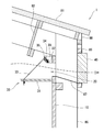
- the ventilation structure 1 of the present embodiment includes a vent 20 formed in the upper part of the side wall 10 that is a wall of a poultry house, and a vent that opens and closes the vent 20 and opens the vent 20 when power supply is stopped.
- An adjustment device 30 and a light shielding ventilation member 40 covering the ventilation hole 20 are provided.
- the light shielding ventilation member 40 has a plurality of thin plate members 41 arranged in parallel at intervals, bent, bent, and inclined. At least one of them forms a ventilation space 42 through which light does not pass but air naturally passes.
- the poultry house has an elongated shape with a length in the direction parallel to the wing of several tens to 100 meters and a length in the direction perpendicular to the wing of several tens to 30 meters.
- a plurality of cage rows extending in parallel directions are arranged side by side.
- the air vent 20 is formed by providing a gap between the upper end of the side wall 10 and the roof 81. More specifically, the space in the attic is partitioned by a partition plate 82 suspended from the roof 81 along the side wall 10 inside the side wall 10, and the lower end side of the partition plate 82 and the upper end side of the side wall 10. In between, the vent 20 is open.
- vent 20 is provided over the entire length of the side wall 10 and is divided into a plurality of units. Furthermore, the air flow adjusting device 30 is provided for each unit of the air vent 20 and can adjust the opening degree of the air vent 20 for each unit.
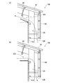
- the air flow adjusting device 30 has a flat plate-like rotary plate 31 that is rotatably supported on one side and a rotary plate drive mechanism that rotates the rotary plate 31 in the vicinity of the upper end of the side wall 10.
- the rotation plate 31 is configured to rotate about an axis parallel to the side wall 10, and a plurality of the rotation plates 31 are connected to each other so as to have a length corresponding to the length of the vent hole 20 of one unit as a whole.
- the rotating plate drive mechanism has a main wire 32 having one end wound around a winch (not shown) driven by a motor. The other end of the main wire 32 is stretched along the side wall 10 by being fixed to a bracket (not shown) protruding from the side wall 10 via a spring.
- One end of the sub wire 33 is attached in the vicinity of the free end of each of the plurality of rotating plates 31 belonging to the same unit, and the other end of the sub wire 33 is connected to the main wire 32.
- the auxiliary wire 33 changes its direction by being hung around a first pulley 34 and a second pulley 35 attached to a support plate 39 projecting from the side wall 10 for each rotation plate 31, and downward due to its own weight.
- the rotating plate 31 to be rotated is pulled from the upper side.
- the poultry house includes a plurality of outer pillars 85 that are suspended at regular intervals so as to be in contact with the outer surface of the side wall 10. This is because if there are pillars and piers in the internal space of the poultry house, dust and the like are likely to accumulate there, so that the internal structure of the poultry house is kept hygienic without forming irregularities as much as possible. .
- the light shielding ventilation member 40 is fixed to the outer pillar 85 so as to be sandwiched from above and below by two crosspieces 86 spanned between the outer pillars 85. Accordingly, a gap corresponding to the thickness of the outer column 85 exists between the light shielding ventilation member 40 and the side wall 10.
- a partition wall 87 extending along the side wall 10 is provided between the upper end of the side wall 10 and the crosspiece 86 that supports the light shielding ventilation member 40 from below, and the crosspiece that supports the light shielding ventilation member 40 from above is provided.
- a partition wall 88 blocks between the material 86 and the lower surface of the roof 81.
- the light shielding ventilation member 40 of the present embodiment as shown in FIG. 4, a large number of thin plate materials 41 whose cross sections are curved in a W shape form a ventilation space 42 between adjacent thin plate materials 41. It is the structure supported by the frame 49 so that it may be arranged in parallel at intervals. The degree of curvature of the thin plate material 41 is set so that light traveling straight does not pass through the ventilation space 42 even if the incident angle of sunlight changes.
- the light shielding ventilation member 40 is formed in a length that can cover the ventilation hole 20 provided over the entire length of the side wall 10 as a whole by connecting a plurality of light shielding ventilation members 40.
- the ventilation structure 1 of the present embodiment includes an air inlet formed in one of a pair of wife surfaces orthogonal to the ridge, and an exhaust port formed in the other wife surface (both are Not shown).
- Each of the air inlet and the air outlet has a large area that is 1/2 or more of the area of the wife surface.
- the air inlet is covered with a cooling pad made of paper or nonwoven fabric with high water absorption.
- a plurality of large exhaust fans are attached to the exhaust port.
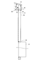
- the ventilation structure 1 of the present embodiment includes an emergency door 51 (see FIG. 3) that opens and closes a lower opening 50 provided through the lower portion of the side wall 10.
- an urging member for urging the emergency door 51 in the opening direction is attached to the inner surface of the emergency door 51.
- Tubular members whose axial directions are located on the same line when the emergency door 51 is closed are respectively attached to the upper part of the inner surface of the emergency door 51 and the upper part of the frame of the lower opening 50.
- An electromagnet is provided in the vicinity of the upper portion of the frame body in the side wall 10, and one end of the wire is hooked on the upper end of the attracted member that is attracted to the electromagnet and extends in the vertical direction and tilts when not attracted.
- the other end of the wire is wound around a pulley attached to the side wall 10 in the vicinity of the upper portion of the frame on the side opposite to the electromagnet, and a weight is suspended from the end. Therefore, in a state where power is supplied and the attracted member is attracted to the electromagnet, the wire is stretched along the side wall 10 in the upper part of the frame.
- a hook member is connected to the wire via a string-like member.
- the exhaust fan is operated to exhaust air from the exhaust port, and forced ventilation is performed by taking in air from the inlet or vent 20.
- air is taken in from the inlet.
- air can distribute
- the temperature of the air taken in through the cooling pad which has been lowered by the removal of heat of vaporization of water, is lowered by flowing, dripping and spraying water to the cooling pad covering the inlet port,
- the inside of the poultry house can be cooled more effectively.
- it since it is coat
- the opening degree of the vent hole 20 can be adjusted for each unit by the vent adjustment device 30 provided for each unit. .
- the main wire 32 is wound up by the winch by driving the motor, the rotating plate 31 is pulled and rotated upward by the sub wire 33 connected thereto, and the opening degree of the vent 20 is small.
- the main wire 32 is drawn out by the winch, the sub wire 33 is loosened, so that the rotating plate 31 is rotated downward by its own weight, and the opening degree of the vent hole 20 is increased.
- the ventilation adjustment device 30 adjusts so that the opening degree of the vent hole 20 of the unit close to the exhaust port is larger than the opening degree of the vent hole 20 of the unit close to the inlet port.
- Such adjustment of the opening degree of the vent hole 20 can be controlled by a computer or a programmable controller based on detection of a temperature sensor provided in the vicinity of the vent hole 20 for each unit of the vent hole 20, for example.
- the inlet and the vent 20 can be used together for taking in the outside air. Further, in the mode of taking air through the vent 20, it is not necessary that all the vents 20 of the plurality of units are open, and the vents 20 of one or more units are closed by the rotating plate 31. Also good.
- the rotation plate 31 When the supply of power is stopped, as shown in FIG. 2, the rotation plate 31 is rotated in the opening direction in the vent holes 20 of all the units.
- the rotation adjustment plate 30 rotates the rotation plate 31 by switching from driving the motor using electric power supplied from a commercial power supply to driving the motor using electric power supplied from a battery.
- vent hole 20 formed in the upper part of the side wall 10 is opened, so that the air in the poultry house that is naturally warmed by the bird's body temperature is discharged smoothly from the vent hole 20 to the outside.
- the vent hole 20 is covered with a light-shielding vent member 40 that allows air to pass through naturally but does not allow light to pass therethrough, thereby preventing sunlight from entering the poultry house through the vent hole 20 that has been released. .
- the emergency door 51 is opened and the lower opening 50 is opened as shown in FIG.
- the attracted member that has been attracted to the electromagnet at the time of energization is tilted away from the electromagnet, and the wire with one end hooked to the upper end is released to act on the weight. It is pulled by gravity and falls.
- the emergency door 51 is opened by the urging by the urging member, and the lower opening 50 is opened.
- the air heated in the poultry house and heated to high temperature is exhausted to the outside from the vent hole 20 released at the upper part of the side wall 10, and fresh from the outside through the lower opening 50 released at the lower part of the side wall 10.
- the air inlet In the winter mode, when the outside air is not taken in from the wife's air inlet, the air inlet is blocked by a heat insulation panel, etc. The inlet is open through. Thereby, in addition to the lower opening 50, outside air also flows from the inlet as warm air in the poultry house is discharged from the vent 20 to the outside. Therefore, even in the summer season when the temperature in the poultry house is likely to rise due to a power failure, the temperature rise in the poultry house is effectively suppressed.
- the vent 20 for discharging air from the inside of the poultry house is provided. Since it is provided in the upper part of the side wall 10, natural ventilation can be performed smoothly when the supply of power is stopped. Further, although the vent 20 is provided at the upper part of the side wall 10, it is covered with the light shielding vent 40, so that sunlight does not enter from the released vent 20.
- a lower opening 50 that opens at the bottom of the side wall 10 when the supply of power is stopped is provided. Accordingly, since the outside air flows from the lower opening 50 as the air warmed in the poultry house is discharged from the vent hole 20, natural ventilation can be performed very smoothly.
- both the forced ventilation during normal power supply and natural ventilation when the power supply is stopped are performed using the same equipment, so the poultry house equipment can be used effectively.
- the cost required for the construction of the ventilation structure 1 can be reduced.
- a light shielding ventilation member is used.
- the mouth may be covered.
- vent may be configured to open and close in a double-opening manner.
- vent and the lower opening are immediately opened when the power supply is stopped.
- the vent and the lower opening can be opened.
Landscapes
- Life Sciences & Earth Sciences (AREA)
- Environmental Sciences (AREA)
- Zoology (AREA)
- Animal Husbandry (AREA)
- Biodiversity & Conservation Biology (AREA)
- Housing For Livestock And Birds (AREA)
- Ventilation (AREA)
Abstract
La présente invention se rapporte à une structure de ventilation de poulailler capable d'effectuer une ventilation de façon ininterrompue pendant une coupure de courant. Une structure de ventilation (1) est pourvue : d'un orifice de ventilation (20) formé sur la partie supérieure d'une paroi (10) d'un poulailler ; d'un dispositif de réglage de ventilation (30) permettant d'ouvrir et de fermer l'orifice de ventilation, le dispositif de réglage de ventilation (30) ouvrant l'orifice de ventilation lorsque l'alimentation électrique est arrêtée ; et d'un élément de ventilation de protection contre la lumière (40) permettant de recouvrir l'orifice de ventilation. Un espace de ventilation à travers lequel la lumière ne passe pas mais l'air passe naturellement est formé dans l'élément de ventilation de protection contre la lumière par une courbe, un coude, et/ou une inclinaison dans une pluralité de plaques minces disposées en parallèle, de telle sorte que des intervalles sont présents entre celles-ci.
Applications Claiming Priority (2)
| Application Number | Priority Date | Filing Date | Title |
|---|---|---|---|
| JP2014079991A JP6225061B2 (ja) | 2014-04-09 | 2014-04-09 | 鶏舎の換気構造及び鶏舎の換気方法 |
| JP2014-079991 | 2014-04-09 |
Publications (1)
| Publication Number | Publication Date |
|---|---|
| WO2015155902A1 true WO2015155902A1 (fr) | 2015-10-15 |
Family
ID=54287499
Family Applications (1)
| Application Number | Title | Priority Date | Filing Date |
|---|---|---|---|
| PCT/JP2014/065469 Ceased WO2015155902A1 (fr) | 2014-04-09 | 2014-06-11 | Structure et procédé de ventilation de poulailler |
Country Status (2)
| Country | Link |
|---|---|
| JP (1) | JP6225061B2 (fr) |
| WO (1) | WO2015155902A1 (fr) |
Cited By (3)
| Publication number | Priority date | Publication date | Assignee | Title |
|---|---|---|---|---|
| CN108739494A (zh) * | 2018-06-05 | 2018-11-06 | 成都晟兴牧业机械有限公司 | 一种鸡舍断电启动的安全防护电路及系统 |
| US11191255B2 (en) * | 2016-10-21 | 2021-12-07 | New Hope Liuhe Feed Co., Ltd. | Premixed ventilated henhouse |
| CN117461562A (zh) * | 2023-12-26 | 2024-01-30 | 四川省畜牧科学研究院 | 一种楼房猪场环境控制系统 |
Families Citing this family (1)
| Publication number | Priority date | Publication date | Assignee | Title |
|---|---|---|---|---|
| JP7849089B1 (ja) * | 2025-07-14 | 2026-04-21 | 株式会社アキタフーズ | 畜舎の換気システム |
Citations (6)
| Publication number | Priority date | Publication date | Assignee | Title |
|---|---|---|---|---|
| JPS5254587Y2 (fr) * | 1975-02-20 | 1977-12-10 | ||
| JPS5912934B2 (ja) * | 1978-10-07 | 1984-03-27 | 日本配合飼料株式会社 | 入気自動制御装置を備えた無窓動物飼育舎 |
| JPH0285931U (fr) * | 1988-12-21 | 1990-07-06 | ||
| JPH07289106A (ja) * | 1994-04-25 | 1995-11-07 | Azuma Corp:Kk | 飼育舎の開口部開閉装置 |
| JP2004033007A (ja) * | 2002-06-28 | 2004-02-05 | Matsui Kensetsu Kk | 養畜建物 |
| JP2009142588A (ja) * | 2007-12-18 | 2009-07-02 | Gifu Univ | 除菌インレット |
-
2014
- 2014-04-09 JP JP2014079991A patent/JP6225061B2/ja active Active
- 2014-06-11 WO PCT/JP2014/065469 patent/WO2015155902A1/fr not_active Ceased
Patent Citations (6)
| Publication number | Priority date | Publication date | Assignee | Title |
|---|---|---|---|---|
| JPS5254587Y2 (fr) * | 1975-02-20 | 1977-12-10 | ||
| JPS5912934B2 (ja) * | 1978-10-07 | 1984-03-27 | 日本配合飼料株式会社 | 入気自動制御装置を備えた無窓動物飼育舎 |
| JPH0285931U (fr) * | 1988-12-21 | 1990-07-06 | ||
| JPH07289106A (ja) * | 1994-04-25 | 1995-11-07 | Azuma Corp:Kk | 飼育舎の開口部開閉装置 |
| JP2004033007A (ja) * | 2002-06-28 | 2004-02-05 | Matsui Kensetsu Kk | 養畜建物 |
| JP2009142588A (ja) * | 2007-12-18 | 2009-07-02 | Gifu Univ | 除菌インレット |
Cited By (4)
| Publication number | Priority date | Publication date | Assignee | Title |
|---|---|---|---|---|
| US11191255B2 (en) * | 2016-10-21 | 2021-12-07 | New Hope Liuhe Feed Co., Ltd. | Premixed ventilated henhouse |
| CN108739494A (zh) * | 2018-06-05 | 2018-11-06 | 成都晟兴牧业机械有限公司 | 一种鸡舍断电启动的安全防护电路及系统 |
| CN117461562A (zh) * | 2023-12-26 | 2024-01-30 | 四川省畜牧科学研究院 | 一种楼房猪场环境控制系统 |
| CN117461562B (zh) * | 2023-12-26 | 2024-03-29 | 四川省畜牧科学研究院 | 一种楼房猪场环境控制系统 |
Also Published As
| Publication number | Publication date |
|---|---|
| JP2015198618A (ja) | 2015-11-12 |
| JP6225061B2 (ja) | 2017-11-01 |
Similar Documents
| Publication | Publication Date | Title |
|---|---|---|
| JP6225061B2 (ja) | 鶏舎の換気構造及び鶏舎の換気方法 | |
| KR101115314B1 (ko) | 배연 기능을 구비한 환기장치 | |
| US20220361437A1 (en) | Evaporative cooling system for an animal barn | |
| JP4382140B1 (ja) | 畜舎の換気装置および畜舎の換気方法 | |
| JPWO2017199359A1 (ja) | 鶏舎の換気方法 | |
| JP6117535B2 (ja) | 空気循環機能を備えた引戸式ドアの戸袋構造 | |
| KR101532737B1 (ko) | 이중 개폐식 에어 하우스 | |
| US20160131380A1 (en) | Method and System for Eliminating Air Pockets, Eliminating Air Stratification, Minimizing Inconsistent Temperature, and Increasing Internal Air Turns | |
| KR20160115271A (ko) | 에어 하우스 | |
| CA2967088C (fr) | Un appareil de rideau d'air | |
| JP5907410B2 (ja) | 浴室空調装置 | |
| JP6372708B2 (ja) | 鶏舎 | |
| JP5974481B2 (ja) | 栽培施設 | |
| JP4584968B2 (ja) | 貯蔵庫 | |
| JP7713228B2 (ja) | 鶏舎空調システム | |
| JP2017032246A (ja) | 送風装置、及びこれを用いた送風システム | |
| KR20220065158A (ko) | 콘테이너형 밀폐식 육계사육 시스템 | |
| KR101432611B1 (ko) | 덕트공조시스템의 에어커튼을 방지할 수 있는 댐퍼장치 | |
| BE1018575A3 (fr) | Rideau d'air a recuperation de calories. | |
| US20170292724A1 (en) | Method of operation of a ventilation system having intake and blowout ports | |
| JP5666360B2 (ja) | 畜舎 | |
| JPS63233232A (ja) | ウインドレス鶏舎の換気装置 | |
| JP2008170053A (ja) | 浴室暖房乾燥機 | |
| CN120323333A (zh) | 一种垂直通风型猪舍的混风系统 | |
| JP2005249344A (ja) | 空気循環装置 |
Legal Events
| Date | Code | Title | Description |
|---|---|---|---|
| 121 | Ep: the epo has been informed by wipo that ep was designated in this application |
Ref document number: 14888791 Country of ref document: EP Kind code of ref document: A1 |
|
| NENP | Non-entry into the national phase |
Ref country code: DE |
|
| 122 | Ep: pct application non-entry in european phase |
Ref document number: 14888791 Country of ref document: EP Kind code of ref document: A1 |