WO2015156031A1 - 通信端末および無線センサネットワークシステム - Google Patents
通信端末および無線センサネットワークシステム Download PDFInfo
- Publication number
- WO2015156031A1 WO2015156031A1 PCT/JP2015/054233 JP2015054233W WO2015156031A1 WO 2015156031 A1 WO2015156031 A1 WO 2015156031A1 JP 2015054233 W JP2015054233 W JP 2015054233W WO 2015156031 A1 WO2015156031 A1 WO 2015156031A1
- Authority
- WO
- WIPO (PCT)
- Prior art keywords
- sensor
- sensor node
- host
- wireless
- communication terminal
- Prior art date
- Legal status (The legal status is an assumption and is not a legal conclusion. Google has not performed a legal analysis and makes no representation as to the accuracy of the status listed.)
- Ceased
Links
Images




Classifications
-
- H—ELECTRICITY
- H04—ELECTRIC COMMUNICATION TECHNIQUE
- H04Q—SELECTING
- H04Q9/00—Arrangements in telecontrol or telemetry systems for selectively calling a substation from a main station, in which substation desired apparatus is selected for applying a control signal thereto or for obtaining measured values therefrom
-
- H—ELECTRICITY
- H04—ELECTRIC COMMUNICATION TECHNIQUE
- H04W—WIRELESS COMMUNICATION NETWORKS
- H04W24/00—Supervisory, monitoring or testing arrangements
- H04W24/08—Testing, supervising or monitoring using real traffic
-
- H—ELECTRICITY
- H04—ELECTRIC COMMUNICATION TECHNIQUE
- H04W—WIRELESS COMMUNICATION NETWORKS
- H04W4/00—Services specially adapted for wireless communication networks; Facilities therefor
- H04W4/20—Services signaling; Auxiliary data signalling, i.e. transmitting data via a non-traffic channel
-
- H—ELECTRICITY
- H04—ELECTRIC COMMUNICATION TECHNIQUE
- H04W—WIRELESS COMMUNICATION NETWORKS
- H04W52/00—Power management, e.g. Transmission Power Control [TPC] or power classes
- H04W52/02—Power saving arrangements
- H04W52/0209—Power saving arrangements in terminal devices
- H04W52/0212—Power saving arrangements in terminal devices managed by the network, e.g. network or access point is leader and terminal is follower
- H04W52/0216—Power saving arrangements in terminal devices managed by the network, e.g. network or access point is leader and terminal is follower using a pre-established activity schedule, e.g. traffic indication frame
-
- H—ELECTRICITY
- H04—ELECTRIC COMMUNICATION TECHNIQUE
- H04W—WIRELESS COMMUNICATION NETWORKS
- H04W52/00—Power management, e.g. Transmission Power Control [TPC] or power classes
- H04W52/02—Power saving arrangements
- H04W52/0209—Power saving arrangements in terminal devices
- H04W52/0212—Power saving arrangements in terminal devices managed by the network, e.g. network or access point is leader and terminal is follower
- H04W52/0219—Power saving arrangements in terminal devices managed by the network, e.g. network or access point is leader and terminal is follower where the power saving management affects multiple terminals
-
- H—ELECTRICITY
- H04—ELECTRIC COMMUNICATION TECHNIQUE
- H04W—WIRELESS COMMUNICATION NETWORKS
- H04W52/00—Power management, e.g. Transmission Power Control [TPC] or power classes
- H04W52/02—Power saving arrangements
- H04W52/0209—Power saving arrangements in terminal devices
- H04W52/0261—Power saving arrangements in terminal devices managing power supply demand, e.g. depending on battery level
- H04W52/0274—Power saving arrangements in terminal devices managing power supply demand, e.g. depending on battery level by switching on or off the equipment or parts thereof
-
- H—ELECTRICITY
- H04—ELECTRIC COMMUNICATION TECHNIQUE
- H04Q—SELECTING
- H04Q2209/00—Arrangements in telecontrol or telemetry systems
- H04Q2209/40—Arrangements in telecontrol or telemetry systems using a wireless architecture
-
- H—ELECTRICITY
- H04—ELECTRIC COMMUNICATION TECHNIQUE
- H04Q—SELECTING
- H04Q2209/00—Arrangements in telecontrol or telemetry systems
- H04Q2209/80—Arrangements in the sub-station, i.e. sensing device
- H04Q2209/84—Measuring functions
- H04Q2209/845—Measuring functions where the measuring is synchronized between sensing devices
-
- H—ELECTRICITY
- H04—ELECTRIC COMMUNICATION TECHNIQUE
- H04W—WIRELESS COMMUNICATION NETWORKS
- H04W84/00—Network topologies
- H04W84/18—Self-organising networks, e.g. ad-hoc networks or sensor networks
-
- Y—GENERAL TAGGING OF NEW TECHNOLOGICAL DEVELOPMENTS; GENERAL TAGGING OF CROSS-SECTIONAL TECHNOLOGIES SPANNING OVER SEVERAL SECTIONS OF THE IPC; TECHNICAL SUBJECTS COVERED BY FORMER USPC CROSS-REFERENCE ART COLLECTIONS [XRACs] AND DIGESTS
- Y02—TECHNOLOGIES OR APPLICATIONS FOR MITIGATION OR ADAPTATION AGAINST CLIMATE CHANGE
- Y02D—CLIMATE CHANGE MITIGATION TECHNOLOGIES IN INFORMATION AND COMMUNICATION TECHNOLOGIES [ICT], I.E. INFORMATION AND COMMUNICATION TECHNOLOGIES AIMING AT THE REDUCTION OF THEIR OWN ENERGY USE
- Y02D30/00—Reducing energy consumption in communication networks
- Y02D30/70—Reducing energy consumption in communication networks in wireless communication networks
Definitions
- the present invention relates to a communication terminal and a wireless sensor network system, and more particularly to a communication terminal capable of power saving communication and a wireless sensor network system to which the communication terminal can be applied.
- a wireless sensor network system is disclosed (for example, see Patent Document 1).
- a plurality of sensor nodes always turn on receivers in a plurality of sensor nodes in order to maintain a state in which signals from a host can always be received even after transmission of wireless transmission data is completed. It is necessary to keep.
- the reception circuit is always turned on to be in a reception standby state. I had to do it. For this reason, power consumption is relatively large.
- An object of the present invention is to provide a communication terminal capable of power saving communication and a wireless sensor network system to which this communication terminal can be applied.
- a sensor that can collect sensor information at a self-supporting timing, a control unit that is connected to the sensor and can process the sensor information, and is connected to the control unit Connected to the memory, a wireless transmission / reception unit connected to the control unit, an antenna connected to the wireless transmission / reception unit and capable of wireless transmission of the sensor information or a result of arithmetic processing of the sensor information, and connected to the control unit
- Sensor node communication terminal comprising a power supply unit configured to be connected to the control unit and capable of receiving the second wireless transmission data from the host side for a predetermined period after the transmission of the first wireless transmission data is completed.
- a control unit a memory connected to the control unit, a radio transmission / reception unit connected to the control unit, and an antenna connected to the radio transmission / reception unit
- a host communication terminal collects sensing data from the sensor nodes via wireless communication and designates a change in communication speed for a plurality of sensor nodes in accordance with the received electric field strength of the received radio waves.
- the apparatus includes a plurality of sensor nodes and a host capable of receiving the first wireless transmission data from the plurality of sensor nodes constantly or periodically.
- a wireless sensor network system is provided, wherein the second wireless transmission data from the host side can be received for a predetermined period after transmission of wireless transmission data is completed.
- a sensor that can collect sensor information at a self-supporting timing, a control unit that is connected to the sensor and can process the sensor information, and the control unit A connected memory; a wireless transmission unit connected to the control unit; an antenna connected to the wireless transmission unit and capable of performing wireless transmission of the sensor information or a result of arithmetic processing of the sensor information; and the control unit A wireless sensor network comprising a plurality of sensor nodes including a connected power supply unit, a timer connected to the control unit, and a host capable of receiving wireless transmission data from the plurality of sensor nodes constantly or periodically A system is provided.
- the present invention it is possible to provide a communication terminal capable of power saving communication and a wireless sensor network system to which this communication terminal can be applied.
- FIG. 1 is a schematic configuration diagram of a wireless sensor network system to which a communication terminal according to a first embodiment can be applied.
- FIG. 4 is a schematic timing chart for explaining a sleep time Ts between transmission data in a sensor node functioning as a communication terminal according to the first embodiment.
- a schematic timing chart of a data signal in the sensor node Pi In the wireless sensor network system to which the communication terminal according to the first embodiment can be applied, (a) a schematic timing chart of a data signal in the sensor node Pi, (b) in the host H corresponding to FIG. The typical timing chart figure of a data signal.
- an operation flowchart of wireless communication between the sensor node Pi and the host H (the absence of the flag FLG and transmission from the sensor node side to the host) A type in which a reception window time is always provided after.
- an operation flowchart of wireless communication between the sensor node Pi and the host H (after the flag FLG is defined and transmitted from the sensor node side to the host) Next, whether or not the reception window time is provided is notified by the value indicated by the flag FLG included in the transmission).
- the sensor block communication terminal which concerns on 2nd Embodiment Comprising: The typical block block diagram of the sensor node provided with a photovoltaic device. The typical bird's-eye view block diagram of the timer clock using the optical sensor applicable to the sensor node communication terminal which concerns on 2nd Embodiment.
- the sensor node communication terminal is a pattern diagram showing the relationship between the power generation amount P O and time t (day) of the photovoltaic device.
- a wireless sensor network system to which a communication terminal according to a comparative example can be applied, (a) a schematic timing chart of a data signal at the sensor node P1, (b) a schematic timing chart of a data signal at the sensor node P2, (c) ) A schematic timing chart of a data signal in the sensor node Pn.
- FIG. 4C is a schematic timing chart of a data signal in the sensor node Pn.
- FIG. 4B is a schematic diagram showing the relationship between the communication speed D (kbps) and the reception sensitivity S (dBm) between the host H and the sensor node Pi.
- A Schematic block configuration diagram of a host capable of wireless communication with a communication terminal according to the fourth embodiment
- B Schematic block configuration diagram of a sensor node functioning as a communication terminal according to the fourth embodiment.
- the communication terminal which concerns on the modification of 4th Embodiment, Comprising: The typical block block diagram of the sensor node provided with a photovoltaic device.
- a wireless sensor network system 100 to which a communication terminal (sensor node) 20 according to the first embodiment is applicable includes a plurality of sensor nodes 20 (P 1 , P 2 ,..., P i , P i + 1 ,..., P n ) and a host 10 that can receive the first wireless transmission data from the plurality of sensor nodes 20 constantly or periodically.
- the reception frequency in the host 10 is more frequent than the transmission frequency of the sensor node 20.
- the host 10 is a base station, and may be disposed on a support column 15 having a predetermined height, for example.
- the plurality of sensor nodes 20 can receive the second wireless transmission data from the host 10 side only for a predetermined short period after the transmission of the first wireless transmission data.
- the first wireless transmission data is sent from the plurality of sensor nodes 20 (P 1 , P 2 ,..., P i , P i + 1 ,..., P n ) to the host 10 at a predetermined timing. Sent.
- the second wireless transmission data is transmitted from the host 10 side to the plurality of sensor nodes 20 (P 1 , P 2 ,..., P i , P i only for a predetermined short period after the transmission of the first wireless transmission data. +1 ,..., P n ).
- the wireless sensor network system 100 to which the communication terminal 20 according to the first embodiment can be applied includes a plurality of sensor nodes 20 (P 1 , P 2 ,..., P i , P i + 1 ,. ), It is possible to receive the transmission data from the host 10 only for a predetermined short period after the transmission of the wireless transmission data, thereby reducing the power consumption.
- a plurality of sensor nodes 20 (P 1, P 2, ⁇ , P i, P i + 1, ..., P n) in, compared with the case where a state capable of receiving constantly wirelessly transmits data after end of transmission
- it is not necessary to always turn on the receivers in the plurality of sensor nodes 20 (P 1 , P 2 ,..., P i , P i + 1 ,..., P n ).
- the information collected in the host 10 is supplied to the cloud computing system using the Internet line or the like, and can be integratedly managed.
- the plurality of sensor nodes 20 are sensor information at independent timing, as will be described later in the description of FIG.
- Sensor 21 that can be collected at the place where the sensor is installed, a memory 22 connected to the sensor 21, a control unit 24 that is connected to the memory 22 and can process sensor information, and a wireless transmission / reception connected to the control unit 24 Unit (RF) 26, connected to the wireless transmission / reception unit 26, the antenna 28 capable of wirelessly transmitting sensor information or the result of calculating sensor information, the power supply unit 32 connected to the control unit 24, and the control unit 24 And a connected timer 30.
- RF control unit
- the memory 22 stores the sensor information acquired by the sensor 21.
- the sensor information acquired by the sensor 21 includes, for example, light, temperature, humidity, pressure, vibration, strain, inclination, switch information, depending on the application of the wireless sensor network system 100 to which the communication terminal (sensor node) 20 is applied. Etc. are included.
- an energy harvesting device such as a solar panel is mainly used.
- it can be applied to a structure in which this is replaced with a battery or provided in a hybrid. This is because the purpose of extending the life of the battery is the same.
- wireless sensor network system for bridges As a wireless sensor network system to which the communication terminal (sensor node) 20 according to the first embodiment can be applied, a schematic bird's-eye view configuration of the wireless sensor network system 300 for bridges is expressed as shown in FIG.
- the bridge wireless sensor network system 300 to which the communication terminal (sensor node) 20 according to the first embodiment can be applied includes a plurality of sensor nodes 20 11 , 20 12 ,..., 20 21 , as shown in FIG. 20 22, ..., 20 31, 20 32, ..., 20 41, 20 42, ... and a plurality of sensor nodes 20 11, 20 12, ..., 20 21, 20 22, ..., 20 31, 20 32, ..., , 20 42 ,... Are provided with hosts 10 1 , 10 2 , 10 3, and 10 4 that can receive the first wireless transmission data from 20 41 , 20 42 ,.
- the reception frequency in the host 10 is more frequent than the transmission frequency of the sensor node 20.
- the hosts 10 1 , 10 2 , 10 3, and 10 4 may be disposed at a connection portion between the columns 301, 302, 303, and 304 having a predetermined height and the road (or railroad track) 305.
- a plurality of wires 306 are connected between the columns 301, 302, 303, and 304 and the road (or railroad track) 305, and the road (or railroad track) 305 is connected by the columns 301, 302, 303, and 304. Is supporting.
- a plurality of sensor nodes 20 11 , 20 12 ,..., 20 21 , 20 22 ,..., 20 31 , 20 32 ,..., 20 41 , 20 42 , etc. are composed of a plurality of wires 306 and a road (or railroad track) 305. It may be arranged in the connection part.
- a plurality of sensor nodes 20 11, 20 12, ..., only a predetermined short period after the transmission ends the first radio transmission data is capable of receiving a second radio transmission data from the host 10 1 side.
- the first wireless transmission data is transmitted from the plurality of sensor nodes 20 11 , 20 12 ,... To the host 10 1 at a predetermined timing.
- the communication terminal 20 for bridges wireless sensor network system 300 can be applied to according to the first embodiment, a plurality of sensor nodes 20 11, 20 12, ..., 20 21, 20 22, ..., 20 31, 20 32, ... - 20 41, 20 42, in ..., only a predetermined short period after the transmission end radio transmission data, by which a state capable of receiving the transmission data from the host 10 1, 10 2, 10 3, 10 4 side Low power consumption. That is, since it is not necessary to always turn on the receivers in the plurality of sensor nodes, the power consumption is reduced.
- Information collected in the hosts 10 1 , 10 2 , 10 3, and 10 4 is supplied to a cloud computing system using an Internet line or the like, and can be integratedly managed.
- the sensor 21 that can collect sensor information at a self-supporting location
- the control unit 24 that is connected to the sensor 21 and can process the sensor information
- the memory 22 that is connected to the control unit 24
- a wireless transmission / reception unit (RF) 26 connected to the control unit 24, an antenna 28 connected to the wireless transmission / reception unit 26, and capable of wirelessly transmitting sensor information or a result obtained by processing the sensor information; and a control unit 24.
- a power supply unit 32 and a timer 30 connected to the control unit 24.
- sensor information acquired by the sensor 21 is stored in the memory 22.
- the sensor information includes, for example, light, temperature, humidity, pressure, vibration, distortion, inclination, tension, and the like.
- the power source unit 32 for example, an energy harvesting device such as a solar panel is mainly used. On the other hand, it can be applied to a structure in which this is replaced with a battery or provided in a hybrid.
- wireless transmission / reception may be performed by selecting one of the hosts arranged on both sides. Further, as will be described later in the third embodiment, a method for avoiding data collision may be applied.
- Wireless sensor network system 200 for farms As a wireless sensor network system to which the communication terminal (sensor node) 20 according to the first embodiment can be applied, a schematic bird's-eye view configuration of the farm wireless sensor network system 200 is expressed as shown in FIG.
- Wireless sensor network system 200 for farms as shown in FIG. 3, may be composed of a plurality of small wireless sensor for farm network system 200 1 ⁇ 200 2 ⁇ ... ⁇ 200 m.
- the plurality of small-scale farm wireless sensor network systems 200 1 , 200 2 ,..., 200 m may be divided, for example, in units of cultivated crops.
- the farm wireless sensor network system 200 to which the communication terminal (sensor node) 20 according to the first embodiment can be applied includes a plurality of sensor nodes 20 11 , 20 12 ,. 20 21 ⁇ 20 22 ⁇ ... ⁇ 20 2n, ⁇ , 20 and m1 ⁇ 20 m2 ⁇ ... ⁇ 20 mn, a plurality of sensor nodes 20 11 ⁇ 20 12 ⁇ ... ⁇ 20 1n, 20 21 ⁇ 20 22 ⁇ ... ⁇ 20 comprises 2n, ⁇ ⁇ ⁇ , a 20 m1 ⁇ 20 m2 ⁇ ... ⁇ 20 the first radio transmission data from the mn constantly or periodically receivable plurality of hosts 10 1 ⁇ 10 2 ⁇ ... ⁇ 10 m.
- the reception frequency in the host 10 is more frequent than the transmission frequency of the sensor node 20.
- the plurality of sensor nodes 20 11 ⁇ 20 12 ⁇ ... ⁇ 20 1n for example, be radio transmitted between the host 10 1, Similarly, the plurality of sensor nodes 20 21 ⁇ 20 22 ⁇ ... ⁇ 20 2n, a possible radio transceiver with the host 10 2, ..., a plurality of sensor nodes 20 m1 ⁇ 20 m2 ⁇ ... ⁇ 20 mn can be wirelessly transmitted and received between the host 10 m.
- a plurality of sensor nodes 20 11 ⁇ 20 12 ⁇ ... ⁇ 20 1n only a predetermined short period after the transmission ends the first radio transmission data is capable of receiving a second radio transmission data from the host 10 1 side.
- the first wireless transmission data from a plurality of sensor nodes 20 11 ⁇ 20 12 ⁇ ... ⁇ 20 1n, at a predetermined timing and sent to the host 10 1.
- the second radio transmission data is transmitted to the first radio transmission data for a predetermined short period after the transmission end, to a plurality of sensor nodes 20 11 ⁇ 20 12 ⁇ ... ⁇ 20 1n the host 10 1 side .
- Information collected in the hosts 10 1 , 10 2 , 10 3 ,..., 10 m is supplied to a cloud computing system using an Internet line or the like and can be integratedly managed.
- the farm wireless sensor network system 200 to which the communication terminal 20 according to the first embodiment can be applied includes a plurality of sensor nodes 20 11 , 20 12 ,..., 20 1n , 20 21 , 20 22 ,. ..., the state in 20 m1 ⁇ 20 m2 ⁇ ... ⁇ 20 mn, which can receive the transmission data of the radio transmission data for a predetermined short period after transmission completion from the host 10 1 ⁇ 10 2 ⁇ ... ⁇ 10 m side
- power consumption is reduced. That is, since it is not necessary to always turn on the receivers in the plurality of sensor nodes, the power consumption is reduced.
- a sensor 21 that can collect sensor information at a self-supporting location, a control unit 24 that is connected to the sensor 21 and that can process the sensor information, and a memory that is connected to the control unit 24 22, a wireless transmission / reception unit (RF) 26 connected to the control unit 24, an antenna 28 connected to the wireless transmission / reception unit 26 and capable of wirelessly transmitting sensor information or a result of processing sensor information, and a control unit 24
- the power supply part 32 connected and the timer 30 connected to the control part 24 are provided.
- sensor information acquired by the sensor 21 is stored in the memory 22.
- the sensor information includes, for example, light, temperature, humidity, atmospheric pressure, vibration, distortion, inclination, switch information, and the like at a place where the farm is installed.
- the power source unit 32 for example, an energy harvesting device such as a solar panel is mainly used. On the other hand, it can be applied to a structure in which this is replaced with a battery or provided in a hybrid.
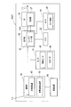
- the schematic block configuration of the host 10 (H) capable of wireless communication with the sensor node communication terminal according to the first embodiment includes a memory 12 and a control connected to the memory 12 as shown in FIG. Unit 14, a radio transmission / reception unit (RF) 16 connected to control unit 14, and an antenna 18 connected to radio transmission / reception unit (RF) 16.
- the memory 12 stores control information necessary for wireless communication between the host 10 and the sensor node 20.
- the control unit 14 executes wireless communication control between the host 10 and the sensor node 20 based on the control information stored in the memory 12.
- the wireless transmission / reception unit (RF) 16 transmits / receives wireless data between the host 10 and the sensor node 20 via the antenna 18.
- the host 10 (H) is a base station, and it is not necessary to provide a power supply unit. Therefore, although not shown in FIG. 4A, power is acquired from various energy sources depending on the application. You may provide the power supply part structure (energy harvesting).
- the host 10 (H) can receive the first wireless transmission data from the sensor node 20 (P) constantly or periodically. Here, when receiving periodically, the reception frequency in a host is more frequent than the transmission frequency of a sensor node.
- the schematic block configuration of the sensor node 20 (P) functioning as the communication terminal according to the first embodiment is a place where sensor information is installed at an independent timing, as shown in FIG.
- RF wireless transmission / reception unit
- an antenna 28 that is connected to the wireless transmission / reception unit 26 and can wirelessly transmit sensor information or a result obtained by processing the sensor information, a power supply unit 32 connected to the control unit 24, and a timer 30 connected to the control unit 24.
- the sensor node 20 (P) can receive the transmission data from the host 10 only for a predetermined short period after the transmission of the wireless transmission data.
- the sensor node 20 (P) functioning as the communication terminal according to the first embodiment is in a state where it can receive transmission data from the host 10 side for a predetermined short period after transmission of wireless transmission data is completed. Low power consumption. That is, since it is not necessary to always turn on the receiver in the sensor node 20 (P), the power consumption is reduced.
- the sensor information includes, for example, light, temperature, humidity, pressure, vibration, distortion, tilt, switch information, noise level, and the like. That is, the sensor 21 can be a sensor that can measure various environmental factors such as a temperature sensor, a humidity sensor, a pressure sensor, a vibration sensor, a strain sensor, a tilt sensor, and a switch information sensor.
- the memory 22 stores sensor information acquired by the sensor 21.
- the memory 12 also stores control information necessary for wireless communication between the host 10 and the sensor node 20.
- the control unit 24 executes wireless communication control between the host 10 and the sensor node 20 based on the sensor information / control information stored in the memory 12. Moreover, the control part 24 can process sensor information.
- a timer 30 is connected to the control unit 24, and timing control and time setting of the sensor node 20 (P) are possible.
- the power supply unit 32 connected to the control unit 24 is supplied with power from various energy sources according to applications such as solar energy, vibration energy of the surrounding environment, wind energy, energy obtained from the thermoelectric generator due to temperature fluctuation, and switch opening / closing. (Energy harvesting) is possible.
- the power supply unit 32 connected to the control unit 24 desirably does not require battery replacement.
- an energy harvesting device such as a solar panel is mainly used.
- it can be applied to a structure in which this is replaced with a battery or provided in a hybrid. This is because the purpose of extending the life of the battery is the same.
- the sensor node 20 (P) functioning as the communication terminal according to the first embodiment is connected to the host 10 (H) in the time width T1 between the timer time t1 and the timer time t2, as shown in FIG. after transmitting the transmission data T X, the time width T2 between timer times t3 and timer time t4 after lapse of a relatively long sleep time Ts, it is possible to transmit the transmission data T X to the host 10 (H).
- the sensor node 20 (P) is capable of intermittent sensing operation, after transmitting the transmission data T X to the host 10 (H), at all times, and the receiver in the sensor node 20 (P) to the on state
- the transmission data T X can be transmitted to the host 10 (H) only in a slight time width T2 after the elapse of the sleep time Ts. For this reason, a power saving operation is possible.
- FIG. 6A a schematic timing chart of the data signal in the sensor node Pi is expressed as shown in FIG. 6A
- FIG. A schematic timing chart of a data signal in the host H corresponding to is expressed as shown in FIG.
- the flag FLG is defined in the wireless communication operation between the sensor node Pi and the host H after the transmission from the sensor node side to the host as shown in the flowchart of FIG. Whether or not the reception window time is subsequently provided corresponds to the type that is notified in advance by the value indicated by the flag FLG included in the transmission.
- FIG. 6A there is an operation mode without FLG.
- the flag FLG is present in the operation of wireless communication between the sensor node Pi and the host H. And a type in which a reception window time is always provided after transmission from the sensor node side to the host).
- the detailed timing chart of the data signal in the sensor node Pi is expressed as shown in FIG. 7A, and the detailed timing chart of the data signal in the host H corresponding to FIG. 7A is shown in FIG. It is expressed as shown in b).
- the transmission / reception patterns include the following seven operation modes (A) to (G) depending on whether the sensor node has a reception window time and a flag in transmission data.
- the flag FLG When the flag FLG is not equipped, the following (A), (D), and (E) modes are selected.
- the flag FLG is equipped, the following (B), (C), (F), and (G) modes are set. It becomes. Details will be described later with reference to FIG.
- the sensor node Pi sets a reception waiting period after transmitting wireless transmission data, but does not receive from the host H.
- the sensor node Pi sets a reception waiting period after transmitting wireless transmission data, and is in a mode of receiving from the host H (control signal only).
- the sensor node Pi After transmitting wireless transmission data, the sensor node Pi sets a reception waiting period, receives from the host H (only data request signal), and then transmits data.
- the sensor node Pi sets a reception waiting period after transmitting wireless transmission data, but does not receive from the host H.
- the sensor node Pi sets a reception waiting period after transmitting wireless transmission data, and is in a mode of receiving from the host H (control signal only).
- (G) A mode in which the sensor node Pi transmits a wireless transmission data, sets a reception standby period, receives from the host H (only a data request signal), and then transmits data.
- (A) A mode in which the sensor node Pi provides a reception waiting period R Xi3 after transmission of the first wireless transmission data T Xi3 , but the host H does not transmit the second wireless transmission data T Xh to the sensor node Pi.
- the sensor node Pi After transmitting the first wireless transmission data T Xi3 , the sensor node Pi provides a reception waiting period R Xi3 , and the host H transmits the second wireless transmission data T Xh to the sensor node Pi. In this mode, the sensor node Pi then transmits the third wireless transmission data T Xi4 to the host H.
- the amount of data / number of transmissions is specified by the contents of the data request signal.
- the flag FLG is included in the data currently being transmitted, and indicates whether or not a window time for reception is provided on the sensor node Pi side during a predetermined period after this transmission.
- the second wireless transmission data T Xh is transmitted during the reception waiting period R Xi3 .
- the host side does not send anything during the reception waiting period R Xi3 .
- the case without the time R XI3 standby reception following the first radio transmission data T XI3 as the flag FLG 0 in the first radio transmission data T XI3, the currently received sensor node Pi to the host H side Indicates not to do.
- the sensor node side receives the received control. Operates according to the signal. That is, for example, the time information of the host H is received and synchronized with the clock in the sensor node.
- the flag FLG can be omitted in the case of a system in which the reception window time is always provided after the first wireless transmission data T Xi3 .
- the reception window time is always provided after the first wireless transmission data T Xi3 .
- the first wireless transmission data T Xi3 is transmitted from the sensor node 20 (P i ) to the host 10 (H) at a predetermined timing.
- the second wireless transmission data T Xh is transmitted from the host 10 (H) side to the sensor node 20 (P i ) within a predetermined short period after the transmission of the first wireless transmission data T Xi3. .
- a combination of a plurality of elements such as a determination element for determining whether or not the sensor node 20 (P i ) continues to wait for reception, for example, once every five days, only at midnight at night, etc. In some cases, it may be judged.
- At least one of the determination elements for determining whether or not the sensor node 20 (P i ) continues to wait for reception may be time or information according to time.
- At least one of the determination elements for determining whether or not the sensor node 20 (P i ) continues to wait for reception may be information regarding the number of times. For example, it is possible to open the reception window only once every 5 times or open the reception window only once a day depending on the application. Thus, the reception window R xi2 , R xi3, etc. may not be opened every time depending on the flag FLG indicating whether or not the sensor node 20 (P i ) will continue to wait for reception.
- a determination criterion that is determined in advance by combining information collected by at least one of the determination elements for determining whether or not the sensor node 20 (P i ) continues to wait for reception together with information collected so far. It may be information regarding the match determination result.
- the sensor node turns on the reception circuit “every time” for a short time after transmission.
- the host side always knows the transmission timing to the sensor node, and if the transmission is performed at that time, the sensor node can receive.
- the wireless sensor network system to which the communication terminal according to the first embodiment can be applied, it is not always necessary to turn on the receiving circuit of the sensor node, and only a limited time is required. Less power consumption. On the other hand, the timing that can be transmitted from the host side is limited, but such a delay is acceptable.
- the wireless sensor network system to which the communication terminal according to the first embodiment can be applied, whether or not the sensor node turns on the reception circuit for a short time after transmission is set as the immediately preceding transmission signal. It is indicated by the included flag FLG information, and the receiving circuit is turned on for a short time only after “Yes”. That is, since the power is not turned on every time, the power consumption is further reduced. On the other hand, the timing at which transmission from the host side can be further limited, but the interval at which the reception window opens is usually widened.
- an operation flowchart of wireless communication between the sensor node Pi and the host H (the absence of the flag FLG and transmission from the sensor node side to the host) 8 is a type in which a reception window time is always provided after), as shown in FIG.
- an operation flowchart of wireless communication between the sensor node Pi and the host H (a flag FLG is defined and transmitted from the sensor node side to the host) 9 is a type in which whether or not to provide a reception window time subsequent to the value indicated by the flag FLG included in the transmission) is expressed as shown in FIG.
- the wireless sensor network system to which the communication terminal according to the first embodiment can be applied, there is no flag FLG, and a reception window time is always provided after transmission from the sensor node side to the host (FIG. 8).
- the flag FLG is defined and whether or not a reception window time is subsequently provided after transmission from the sensor node to the host is notified by a value indicated by the flag FLG included in the transmission.
- There are two types (corresponding to the operation flowchart of FIG. 9).
- the type in which the reception window time is always provided after the transmission from the sensor node side to the host without the presence of the flag FLG has a period in which the reception circuit is turned on even if it is a little at every transmission on the sensor node side. In addition, it is only necessary to turn on the receiving circuit instead of every time (for example, once every 10 times, once a day, once every 5 times when the stored energy is higher than a predetermined level). Received).
- the type in which the flag FLG is defined and which is notified in advance by the value indicated by the flag FLG included in the transmission indicates whether or not the reception window time is provided after the transmission from the sensor node to the host is consumed. There is a feature that can reduce power.
- step S1 of FIG. 8 the sensor node transmits data to the host.
- step S2 the sensor node opens the reception window for a short time.
- step S3 the host receives the transmitted data.
- step S4 is there a transmission from the host to the sensor node? Judging.
- step S4 the process proceeds to step S12, and the host enters the next standby state.
- step S13 the process proceeds to step S13, where the sensor node closes the reception window and enters the sleep mode. (The sensor node counts the timer until the next time.)
- step S5 the process will transfer to step S5 and a host will transmit a control signal to a sensor node.
- step S6 the sensor node receives a control signal.
- step S7 the sensor node closes the reception window and executes control.
- step S8 the sensor node enters the sleep mode. (The sensor node counts the timer until the next time.) (K) If YES in step S4, the process proceeds to step S9, and the host transmits a data request signal to the sensor node.
- step S10 the sensor node receives a data request signal.
- step S11 the sensor node closes the reception window, and then returns to step S1, where the sensor node transmits data to the host.
- step S21 of FIG. 9 the sensor node transmits data to the host.
- step S22 is the flag FLG in the transmission data 1 or not? Judging.
- step S25 the host receives the transmitted data.
- step S26 is the flag FLG in the received data 1 or not? Judging.
- step S28 the process proceeds to step S29, and the host transmits a control signal to the sensor node.
- step S30 the sensor node receives a control signal.
- step S31 the sensor node closes the reception window and executes control.
- step S32 the sensor node enters the sleep mode. (The sensor node counts the timer until the next time.) (M) Alternatively, if YES in step S28, the host may move to step S33, and the host may transmit a data request signal to the sensor node.
- step S34 the sensor node receives the data request signal.
- step S35 the sensor node closes the reception window.
- step S21 the process returns to step S21, and the sensor node transmits data to the host.
- step S28 the process proceeds to step S36, and the host enters the next standby state.
- step S37 the process proceeds to step S37, where the sensor node closes the reception window and enters the sleep mode.
- the sensor node counts the timer until the next time.
- ML7396A 915 MHz to 929.7 MHz
- ML7396B 902 MHz to 928 MHz
- ML7396E 863 MHz to 870 MHz.
- G binary- (G) FSK / MSK
- the data communication speed may be compatible with, for example, 50 kbps / 100 kbps / 200 kbps IEEE specifications. 400 kbps is also applicable.
- the transmission output is, for example, 20 mW / 10 mW / 1 mW
- the reception sensitivity is, for example, about ⁇ 100 dBm to ⁇ 70 dBm.
- the first embodiment it is possible to provide a communication terminal capable of power saving communication and a wireless sensor network system to which this communication terminal can be applied.
- FIG. 1 A schematic block configuration of the sensor node 20 (P) that functions as a communication terminal according to the second embodiment and includes the photovoltaic power generation apparatus 40 is expressed as shown in FIG.
- the sensor node 20 (P) functioning as a communication terminal includes a sensor 21 that can collect sensor information at a place where the sensor information is installed, and a sensor 21.
- the control unit 42 that can process sensor information
- the memory 22 connected to the control unit 42
- the wireless transmission / reception unit (RF) 26 connected to the control unit 42
- the wireless transmission / reception unit 26 It includes an antenna 28 capable of wirelessly transmitting sensor information or a result obtained by calculating sensor information, a power supply unit 32 connected to the control unit 42, and a timer 44 connected to the control unit 42.
- the sensor node 20 (P) can receive the transmission data from the host 10 only for a predetermined short period after the transmission of the wireless transmission data.
- the power supply unit 32 includes a photovoltaic power generation device 40 and a power generation amount detection device 50 that is connected to the photovoltaic power generation device 40 and measures the amount of photovoltaic power generation.
- the power generation amount detection device 50 that measures the amount of photovoltaic power generation may have a peak power tracking function.
- the power storage unit 54 may be connected to the power supply unit 32.
- a capacitor, a lithium ion capacitor, an electric double-layer capacitor (EDLC), or the like can be applied.
- the power storage device 54 may be built in the power supply unit 32.
- an energy harvesting device such as a solar panel is mainly used.
- it can be applied to a structure in which this is replaced with a battery or provided in a hybrid. This is because the purpose of extending the life of the battery is the same.
- the power supply unit 32 connected to the control unit 24 includes the photovoltaic power generation device 40 and can acquire power (energy harvesting) from solar energy.
- the power supply unit 32 connected to the control unit 24 desirably does not require battery replacement.
- the sensor 21 includes a vibration sensor 46 and an optical sensor 48, but is not limited thereto.
- the sensor information includes, for example, light, temperature, humidity, pressure, vibration, distortion, tilt, switch information, noise level, and the like. That is, the sensor 21 can be a sensor that can measure various environmental factors such as an optical sensor, a temperature sensor, a humidity sensor, a pressure sensor, a vibration sensor, a strain sensor, a tilt sensor, and a switch information sensor.
- an acceleration sensor formed of a MEMS (Micro Electro Mechanical Systems) element or the like can be applied depending on the application.
- the memory 22 stores sensor information acquired by the sensor 21.
- the memory 12 also stores control information necessary for wireless communication between the host 10 and the sensor node 20.
- the control unit 24 executes wireless communication control between the host 10 and the sensor node 20 based on the sensor information / control information stored in the memory 12. Moreover, the control part 24 can process sensor information.
- a timer 44 is connected to the control unit 24, and timing control and time setting of the sensor node 20 (P) are possible.
- the timer 44 can supply a communication terminal according to the second embodiment and an information source related to the operation timing of the wireless sensor network system to which the communication terminal is applied.
- the sensor node 20 (P) functioning as the communication terminal according to the second embodiment is stopped, for example, malfunctioned, mad (significantly shifted), initialized, for some reason.
- a timer clock 45 that substantially adjusts the time of the timer 44 may be provided when the time is significantly different from the one-day phase, such as when it is restarted.
- the sensor node 20 (P) functioning as a communication terminal according to the second embodiment may include a timer clock 45 using an optical sensor 49 in the timer 44, for example.
- the timer clock 45 includes a housing 70, a slit window 72 formed in the housing 70, and a path 76 drawn on the bottom of the housing 70 by sunlight 74 that has passed through the slit window 72. And an optical sensor 49 disposed substantially at the center.
- the optical sensor 49 disposed in the timer clock 45 may be the same as the optical sensor 48.
- the timer clock 45 applicable to the sensor node 20 (P) uses the optical sensor 49 and can set the output peak point of the optical sensor 49 or the center point of time to substantially noon based on the same principle as the sundial. is there. By providing such a timer clock 45, it is possible to reset the reference time of the timer 44 even in a situation where the absolute time has disappeared. Further, when photovoltaic power generation is not used, the time can be estimated from the output of the optical sensor 49 by looking at the light intensity cycle of the day.
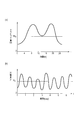
- the relationship between the traffic amount TR measured by the vibration sensor 46 and the time t (h) is schematically represented as shown in FIG. .
- the sensor node communication terminal according to the second embodiment is applied to a wireless sensor network system for bridges, the relationship between the traffic volume TR corresponding to the traffic volume of an automobile or a railway and the time t (h) Is detected by the vibration sensor 46 as sensor information.
- the average value of the traffic volume TR is represented by TR A.
- the vibration sensor 46 may be a load sensor on the bridge
- this assumption is to estimate the time by grasping the laws of trends such as traffic volume in one day. That is, it is assumed that there are many commuting hours in the morning and evening, and that there is a tendency that the nighttime is less than the daytime in the evening. Also, it is assumed that the pattern is different on weekends and holidays. In the case of a railway bridge, it is assumed that the first one after a certain amount of time has passed corresponds to the first departure time of 4:45. In addition, the characteristic of Fig.12 (a) is typical.
- the relationship between the light intensity P measured by the optical sensor 48 and the time t (day) is schematically represented as shown in FIG. .
- the sensor node communication terminal according to the second embodiment is applied to a farm wireless sensor network system
- the light intensity P corresponding to the sunshine time corresponding to the cycle of one day and the time t (day) Is detected as sensor information by the optical sensor 48.
- the average value of the light intensity P is expressed by P A.
- the characteristic of FIG.12 (b) is typical.
- the relationship between the amount of power generated by the photovoltaic device 40 P O and time t (day) is schematically shown in FIG. 13 expressed.
- the photovoltaic power generation device 40 shows a change of the power generation amount P O with respect to time t (day) according to the amount of received sunlight.
- the power generation amount P O exceeds a certain reference value A (corresponding to the operating points A1, A3, A5), when the power generation amount P O falls below a certain reference value A (corresponding to the operating points A2, A4, A6), when power generation amount P O represents the maximum power generation amount (corresponding to the operating point Qmax), in any of the timing when (corresponding to the operating point Qmin) for the power generation amount P O represents a minimum amount of power generation, the timer 44 by the timer clock 45 Can be adjusted.
- the normal power generation amount P O at the point A that the amount of power generation fell, i.e. a point close to the sunrise or sunset, the midpoint A1 and A2, the midpoint of A3 and A4, the midpoint of A5 and A6 is noon
- the reference value A may be set in a hysteresis relationship. That is, for example, the value calculated based on the maximum power generation amount MAX value and the minimum power generation amount MIN value can be used as the reference value A.
- the reference value A may be set by calculating the adjustment amount based on the standard deviation of the power generation amount P O for the past several days.
- the sensor node 20 (P) functioning as a communication terminal according to the second embodiment is in a state where it can receive transmission data from the host 10 side for a predetermined short period after transmission of wireless transmission data is completed. Low power consumption. That is, since it is not necessary to always turn on the receiver in the sensor node 20 (P), the power consumption is reduced.
- the wireless sensor network system to which the communication terminal and the communication terminal according to the second embodiment can be applied can operate in the same manner as the wireless sensor network system to which the communication terminal and the communication terminal according to the first embodiment can be applied. is there. Also, as in the first embodiment, the wireless sensor network system for bridges and the farm error! ⁇ ⁇ ⁇ link are not correct. It is also applicable.
- the second embodiment it is possible to provide a communication terminal capable of resetting time and capable of power saving communication and a wireless sensor network system to which this communication terminal can be applied.
- a plurality of sensor nodes laid on a structure such as a bridge can collect various sensor information at the laying location such as vibration, distortion, inclination, temperature, and various sensor information at substantially the same time.
- Various sensor information collected at substantially the same time is transmitted to a single host by wireless communication for analysis.
- the method of wireless transmission after collecting various types of sensor information from a plurality of sensor nodes at substantially equal intervals there may be a case in which communication is not established due to collision between the wireless signal data.
- the schematic timing chart of the data signal in the sensor node P1 is expressed as shown in FIG. 14A, and the schematic of the data signal in the sensor node P2 is shown.
- the timing chart is expressed as shown in FIG. 14B, and is a schematic timing chart of the data signal in the sensor node Pn, and is expressed as shown in FIG.
- a schematic timing chart of received data in the host H when there is no data collision is expressed as shown in FIG.
- a schematic timing chart of received data in the host H when there is a data collision is expressed as shown in FIG.
- the schematic timing chart of the data signal in the sensor node P1 is expressed as shown in FIG.
- a schematic timing chart of the signal is expressed as shown in FIG. 16B
- a schematic timing chart of the data signal in the sensor node Pn is expressed as shown in FIG.
- various sensor information i collected during the time ti ⁇ ti + 1 is transmitted to the host H during the time t1 ⁇ t2 after the elapse of the timing ⁇ t1 from the time ti + 1.
- various sensor information i collected during the time ti ⁇ ti + 1 is transmitted to the host H during the time t2 ⁇ t3 after the timing ⁇ t2 has elapsed since the time ti + 1.
- various sensor information i collected during the time ti ⁇ ti + 1 is transmitted to the host H during the time tn ⁇ tn + 1 after the elapse of the timing ⁇ tn from the time ti + 1. .
- a plurality of sensor nodes P1, P2, When transmitting various sensor information i collected at substantially the same time ti ⁇ ti + 1 to the host H by wireless communication, the plurality of sensor nodes P1, P2,. It is possible to avoid collision of radio signal data by changing the timing until transmission to the host H by communication at a plurality of sensor nodes P1, P2,.
- timing ⁇ t to be changed in the plurality of sensor nodes P1, P2,... Pn may be set in advance for each of the plurality of sensor nodes P1, P2,.
- the timing ⁇ t to be changed by the plurality of sensor nodes P1, P2,... Pn is a control signal (T Xh in the second wireless transmission data transmitted from the host H to the plurality of sensor nodes P1, P2 ,. : It is possible to readjust according to FIG. 6B and FIG.
- the method of substantially synchronizing the timings of the various sensor information i among the plurality of sensor nodes P1, P2,..., Pn is the same as that of the wireless sensor network system according to the first embodiment shown in FIGS. This is as described with reference to the timing chart and the flowcharts of FIGS.
- Communication terminal (sensor node) 20 for bridges wireless sensor network system 310 can be applied to according to the third embodiment, as shown in FIG. 17, a plurality of sensor nodes 20 11, 20 12, ..., 20 11 ( H), 20 12 (H) , ... ⁇ 20 21, 20 22, ..., 20 21 (H), 20 22 (H), ... ⁇ 20 31, 20 32, ..., 20 31 (H), 20 32 ( H), ... ⁇ 20 41, 20 42, ..., 20 41 (H), 20 42 (H), ... , a plurality of sensor nodes 20 11, 20 12, ..., 20 11 (H), 20 12 (H ), ... ⁇ 20 21, 20 22, ... 20 21 (H), 20 22 (H), ...
- the timing control may be executed between the adjacent hosts 10 1 , 10 2 , 10 3, and 10 4 .
- collision of radio signal data can be avoided so that time does not overlap between the groups of adjacent hosts 10 1 , 10 2 , 10 3, and 10 4 .
- the timing ⁇ t changed by a plurality of sensor nodes may be set in advance for each of the plurality of sensor nodes.
- timing ⁇ t to be changed by the plurality of sensor nodes can be readjusted by a control signal (T Xh : FIG. 6B, FIG. 7) in the second wireless transmission data transmitted from the host to the plurality of sensor nodes. is there.
- the hosts 10 1 , 10 2 , 10 3, and 10 4 may be disposed at a connection portion between the columns 301, 302, 303, and 304 having a predetermined height and the road (or railroad track) 305.
- the suspension bridge structure wire 307 is stretched between the columns 301, 303, 302, and 304, and between the suspension bridge structure wire 307 and the connection portion of the road (or railroad track) 305 in a substantially vertical direction.
- 308 is arranged, and the road (or railroad track) 305 is supported by the columns 301, 302, 303, and 304.
- a plurality of sensor nodes 20 11 , 20 12 ,..., 20 21 , 20 22 ,..., 20 31 , 20 32 ,..., 20 41 , 20 42 , etc. are composed of a plurality of wires 307 and a road (or railroad track) 305. It may be arranged at a connection part (indicated by a black circle).
- a plurality of sensor nodes 20 11 (H), 20 12 (H),... 20 21 (H), 20 22 (H),... 20 31 (H), 20 32 (H) ,. (H), 20 42 (H),... May be arranged at a connection portion (indicated by a white circle) between the wire 307 and the wire 308 of the suspension bridge structure.
- the plurality of sensor nodes 20 11 , 20 12 ,..., 20 11 (H), 20 12 (H),... Can be wirelessly transmitted / received to / from the host 10 1. 21, 20 22, ..., 20 21 (H), 20 22 (H), ... is capable wireless transmitted and received between the host 10 2, a plurality of sensor nodes 20 31, 20 32, ..., 20 31 ( H), 20 32 (H),... Can be wirelessly transmitted to and received from the host 10 3 , and a plurality of sensor nodes 20 41 , 20 42 ,..., 20 41 (H), 20 42 (H),. Can be wirelessly transmitted to and received from the host 10 4 .
- Information collected in the hosts 10 1 , 10 2 , 10 3, and 10 4 is supplied to a cloud computing system using an Internet line or the like, and can be integratedly managed.
- the communication terminal according to the third embodiment and the wireless sensor network system for bridge 310 to which the communication terminal can be applied apply the communication terminal and the communication terminal according to the first and second embodiments. It can operate in the same way as a possible wireless sensor network system.
- the configuration of the sensor node 20 (P) functioning as a communication terminal according to the third embodiment can employ the same configuration as that of the first embodiment and the second embodiment.
- the third embodiment it is possible to provide a communication terminal capable of avoiding collision of radio signal data and capable of power saving communication and a wireless sensor network system to which this communication terminal can be applied.
- FIG. 1 A schematic configuration of a wireless sensor network system 100 to which a communication terminal (sensor node) according to the fourth embodiment can be applied is represented as shown in FIG.
- a wireless sensor network system 100 to which a communication terminal (sensor node) according to the fourth embodiment can be applied includes a plurality of sensor nodes P 1 , P 2 ,..., P i , P i + 1, ..., and P n, a plurality of sensor nodes P 1, P 2, ⁇ , P i, P i + 1, ..., constantly or periodically receives first radio transmission data from the P n Possible host 10.
- the distance between the plurality of sensor nodes P 1 , P 2 ,..., P i , P i + 1 ,..., P n and the host 10 is L 1 , L 2 ,. i , L i + 1 ,..., L n .
- the reception frequency in a host is more frequent than the transmission frequency of a sensor node.
- the plurality of sensor nodes P 1 , P 2 ,..., P i , P i + 1 ,..., P n are the first from the host 10 side for a predetermined short period after the transmission of the first wireless transmission data. 2 Wireless transmission data can be received.
- the first radio transmission data a plurality of sensor nodes P 1, P 2, ⁇ , P i, P i + 1, ..., a P n, at a predetermined timing, is transmitted to the host 10
- the second wireless transmission data is transmitted from the host 10 side to the plurality of sensor nodes P 1 , P 2 ,..., P i , P i + 1 only for a predetermined short period after the transmission of the first wireless transmission data. ,..., Pn .
- Fourth wireless sensor network system 100 can be applied to a communication terminal according to the embodiment of the plurality of sensor nodes P 1, P 2, ⁇ , P i, P i + 1, ..., in P n, wireless Since the transmission data from the host 10 side can be received only for a predetermined short period after the transmission of the transmission data is completed, the power consumption is reduced. That is, a plurality of sensor nodes P 1, P 2, ⁇ , P i, P i + 1, ..., there is no need to have to constantly turn on the receiver in P n, are low power consumption .
- the information collected in the host 10 is supplied to the cloud computing system using the Internet line or the like, and can be integratedly managed.
- wired communication via the Internet line or wireless communication different from the wireless communication in this case can be applied.
- the fourth wireless sensor network system 100 can be applied to a communication terminal according to the embodiment, the plurality of sensor nodes P 1, P 2, ⁇ , P i, P i + 1, ..., P n and the host
- the data communication speed D (kbps) between 10 (H) can be changed.
- the reception sensitivity S is increased and the transmission distance L is increased. As a result, the transmission time becomes longer. On the other hand, when there is sufficient reception sensitivity S, the communication speed D (kbps) is increased. As a result, the transmission time can be shortened, low power consumption operation becomes possible, and necessary power can be suppressed.
- a wireless sensor network system having a plurality of communication speed functions can be provided, which is suitable for applications where a wide area such as a bridge, a farm, or a forest is desired to be covered.
- the fourth wireless sensor network system 100 can be applied to a communication terminal according to the embodiment, the plurality of sensor nodes P 1, P 2, ⁇ , P i, P i + 1, ..., P n and the host By making it possible to change the data communication speed D (kbps) between 10 (H), the total transmission data amount can be suppressed as a result.
- the data communication speed D can be reduced, and as a result, a small amount of data, That is, the total transmission data amount can be suppressed.
- sensor information such as temperature, humidity, and vibration is detected as continuous data. If low data communication rate of the communication is stable, the host 10 (H), the sensor node P 1, P 2, ⁇ , P i, P i + 1, ..., data communication speed relative to P n It is possible to issue a command to increase As a result, the sensor nodes P 1 , P 2 ,..., P i , P i + 1 ,..., P n can transmit a larger amount of data to the host 10 (H).
- a plurality of sensor nodes P 1, P 2, ⁇ , P i, P i + 1, ... if it is desired to operate in an energy harvester to P n, a plurality of sensor nodes P 1, P 2 ,..., P i , P i + 1 ,..., P n , it is desirable that there is no need to transmit signals for maintaining the wireless sensor network in vain. It is possible to implement a wireless sensor network system in which data transmission from the sensor node is performed at a low communication speed, reception opportunities are set in the sensor node for only a short period, and power is saved in the sleep mode during other periods.
- FIG. 19 (a) a schematic timing chart of a data signal in the host H is represented as shown in FIG. 19 (a), and FIG. A schematic timing chart of the data signal in the sensor node Pi corresponding to is represented as shown in FIG.
- the sensor node Pi transmits the wireless transmission data T xP1-1 to the host H at the initial communication speed of 1 kbps, and the host H transmits the wireless reception data R xC1 from the sensor node Pi.
- ⁇ 1 is received, for example, with a received field strength (RSSI) of about ⁇ 100 dBm.
- RSSI received field strength
- the sensor node Pi opens the reception window R xP1-1 and sets the wireless transmission data from the host H to a reception standby state (talk / after / listen mode).
- the sensor node Pi transmits the wireless transmission data T xP1-2 to the host H at the communication speed of 1 kbps, and the host H transmits the sensor node Pi between the times t3 and t4.
- the radio reception data RxC1-2 from is received with RSSI of about -90 dBm, for example.
- the host H transmits wireless transmission data TxC1-1 including an instruction to increase the communication speed to the sensor node Pi in the master rate mode (for example, communication Instructions to increase the speed to 10 kbps).
- an instruction to increase the communication speed to the sensor node Pi in the master rate mode for example, communication Instructions to increase the speed to 10 kbps.
- the sensor node Pi transmits the wireless transmission data T xP1-3 to the host H at a communication speed of 10 kbps, and the host H receives the wireless reception data R xC1 from the sensor node Pi. -3 is received, for example, with an RSSI of about -93 dBm.
- the sensor node Pi opens the reception window R xP1-3 and puts data from the host H into a reception standby state (talk / after / listen mode).
- the communication speed is increased from the initial communication speed of 1 kbps to, for example, 10 kbps.
- the present invention is not limited to this.
- the communication speed may be, for example, 12.5 kbps, 20 kbps,..., 50 kbps, 100 kbps, 200 kbps (supporting IEEE specifications) from the initial communication speed of 1 kbps. 400 kbps is also applicable.
- the time required for transmission by the sensor node is 100 msec for 1 kbps and 10 msec for 10 kbps, and the power consumption of the sensor node can be significantly reduced.
- the amount of data that can be transmitted by the sensor node in one transmission is 100 bits for 1 kbps, 1000 bits for 10 kbps, and a large amount of data can be transmitted.
- the maximum time for one transmission is determined to be 50 msec by the Radio Law, and the amount of data that can be transmitted is limited when the communication speed is low.
- the communication distance that can be transmitted can be extended even if the same transmission power is used as an advantage of low communication speed. This is because the receiving sensitivity of the receiver can be increased as the communication speed decreases.
- the relationship between the transmission distance L (m) and the reception sensitivity S (dBm) between the host H and the sensor node Pi is schematically illustrated.
- the relationship between the communication speed D (kbps) and the reception sensitivity S (dBm) between the host H and the sensor node Pi is schematically represented as shown in FIG. Is done.
- the fourth wireless sensor network system 100 can be applied to a communication terminal according to the embodiment, the plurality of sensor nodes P 1, P 2, ⁇ , P i, P i + 1, ..., P n and the host
- the data communication speed D (kbps) between 10 (H) can be changed, and is effective when used in a relatively wide area (several kilometers) (bridge, tunnel, farm, etc.).
- Communication nodes for low power, especially sensor nodes that use energy harvesters (several centimeters of solar panels, etc.) as power sources are effective when network establishment communication (synchronous communication) is difficult due to power requirements. is there.
- a schematic block configuration of the host 10 (H) capable of wireless communication with the sensor node communication terminal according to the fourth embodiment includes a memory 12 and a control connected to the memory 12 as shown in FIG. Unit 14, a radio transmission / reception unit (RF) 16 connected to control unit 14, and an antenna 18 connected to radio transmission / reception unit (RF) 16.
- RF radio transmission / reception unit
- the host 10 (H) collects sensing data from the sensor nodes P1 to Pn via wireless communication.
- the host 10 (H) has a function capable of dealing with various communication speeds.
- the host 10 (H) has a function of measuring the RSSI of the received radio wave.
- the host 10 (H) has a function of designating a change in communication speed for the sensor nodes P1 to Pn according to RSSI (master rate mode).
- This communication speed change designation signal may be included in the data request signal or control signal (T Xh : FIGS. 6B and 7) in the second wireless transmission data. For this reason, as shown in FIG.
- the wireless transmission / reception unit (RF) 16 includes an RSSI unit 17 that measures the received electric field strength (RSSI) of the received radio wave, and the control unit 14 measures the RSSI unit 17.
- RSSI received electric field strength
- a master rate unit 13 that designates a change in communication speed for the sensor nodes P1 to Pn according to the RSSI is provided.
- a communication speed change designation signal SVM that designates a change in communication speed for the sensor nodes P1 to Pn is supplied from the control unit 14 to the wireless transmission / reception unit (RF) 16, and the wireless transmission / reception unit (RF) 16 causes the antenna 18 to be connected.
- SVM communication speed change designation signal
- the schematic block configuration of the sensor node 20 (P) functioning as a communication terminal according to the fourth embodiment is a place where sensor information is installed at an independent timing, as shown in FIG.
- RF wireless transmission / reception unit
- an antenna 28 that is connected to the wireless transmission / reception unit 26 and can wirelessly transmit sensor information or a result obtained by processing the sensor information, a power supply unit 32 connected to the control unit 24, and a timer 30 connected to the control unit 24.
- the sensor node 20 (P) can receive transmission data from the host 10 side for a predetermined short period after transmission of wireless transmission data (sensing data) is completed. That is, in the first embodiment, as described with reference to FIGS. 6 to 9, the sensor nodes P1 to Pn have a function of detecting the presence or absence of communication from the host H immediately after sensing data transmission ( Talk after listen mode).
- Sensor nodes P1 to Pn are equipped with various sensors and transmit the measured values or the calculation results of the measured values to the host H by wireless communication.
- the sensor nodes P1 to Pn have a function of changing the communication speed in accordance with an instruction from the host (slave rate mode).
- the wireless transmission / reception unit (RF) 26 includes a reception unit 27 that receives an instruction from the host, and the control unit 24 responds to the instruction from the host received by the reception unit 27. And a slave rate unit 25 for instructing the host 10 (H) to change the communication speed.
- the communication speed change instruction signal SVS to the host 10 (H) is supplied from the control unit 24 to the wireless transmission / reception unit (RF) 26, and is transmitted from the wireless transmission / reception unit (RF) 26 to the sensor nodes P1 to Pn via the antenna 28.
- Sent Other configurations are the same as the configuration of the sensor node 20 (P) (FIG. 4B) in the first embodiment.
- a control unit 42 connected to the sensor 21 and capable of processing sensor information, a memory 22 connected to the control unit 42, a wireless transmission / reception unit (RF) 26 connected to the control unit 42, and a wireless transmission / reception unit 26 It includes an antenna 28 that is connected and can wirelessly transmit sensor information or a result obtained by calculating sensor information, a power supply unit 32 connected to the control unit 42, and a timer 44 connected to the control unit 42.
- the sensor node 20 (P) can receive transmission data from the host 10 side for a predetermined short period after transmission of wireless transmission data (sensing data) is completed.
- the power supply unit 32 includes a photovoltaic power generation device 40 and a power generation amount detection device 50 that is connected to the photovoltaic power generation device 40 and measures the amount of photovoltaic power generation.
- the power generation amount detection device 50 that measures the amount of photovoltaic power generation may have a peak power tracking function.
- the power storage unit 54 may be connected to the power supply unit 32.
- a capacitor, a lithium ion capacitor, an electric double-layer capacitor (EDLC), or the like can be applied.
- the power storage device 54 may be built in the power supply unit.
- the sensor nodes P1 to Pn have a function of detecting the presence / absence of communication from the host H immediately after sensing data transmission (talk / talk). After listen mode).
- the sensor nodes P1 to Pn have a function of changing the communication speed in accordance with an instruction from the host (slave rate mode).
- the wireless transmission / reception unit (RF) 26 includes a receiving unit 27 that receives an instruction from the host, and the control unit 24 responds to the instruction from the host received by the receiving unit 27.
- a slave rate unit 43 is provided for instructing the change of the communication speed to 10 (H).
- the communication speed change instruction signal SVS to the host 10 (H) is supplied from the control unit 42 to the wireless transmission / reception unit (RF) 26, and is transmitted from the wireless transmission / reception unit (RF) 26 to the sensor nodes P 1 to Pn via the antenna 28.
- Other configurations are the same as the configuration of the sensor node 20 (P) (FIG. 10) in the second embodiment.
- the fourth embodiment by enabling the data communication speed between the plurality of sensor nodes and the host to be changed, the total transmission data amount can be suppressed, and the communication terminal capable of power saving communication and the communication terminal Can be provided.
- the communication terminal and the wireless sensor network system of the present invention can be applied to a wide area such as a bridge, a farm, and a forest, and various sensor information such as temperature, humidity, vibration, and strain are continuously transmitted in a plurality of sensor node communication terminals. It can be applied to system applications that can be acquired as data and wirelessly transmitted to a host with low power consumption.
Landscapes
- Engineering & Computer Science (AREA)
- Computer Networks & Wireless Communication (AREA)
- Signal Processing (AREA)
- Arrangements For Transmission Of Measured Signals (AREA)
- Mobile Radio Communication Systems (AREA)
- Bridges Or Land Bridges (AREA)
- Quality & Reliability (AREA)
- Physics & Mathematics (AREA)
- Electromagnetism (AREA)
Priority Applications (3)
| Application Number | Priority Date | Filing Date | Title |
|---|---|---|---|
| EP15776784.9A EP3131078B1 (de) | 2014-04-11 | 2015-02-17 | Kommunikationsendgeräte und drahtlossensornetzwerksystem |
| CN201580018930.2A CN106415685B (zh) | 2014-04-11 | 2015-02-17 | 通信终端和无线传感器网络系统 |
| US15/288,040 US10601528B2 (en) | 2014-04-11 | 2016-10-07 | Communication terminal and wireless sensor network system |
Applications Claiming Priority (2)
| Application Number | Priority Date | Filing Date | Title |
|---|---|---|---|
| JP2014082131A JP6322037B2 (ja) | 2014-04-11 | 2014-04-11 | 通信端末および無線センサネットワークシステム |
| JP2014-082131 | 2014-04-11 |
Related Child Applications (1)
| Application Number | Title | Priority Date | Filing Date |
|---|---|---|---|
| US15/288,040 Continuation US10601528B2 (en) | 2014-04-11 | 2016-10-07 | Communication terminal and wireless sensor network system |
Publications (1)
| Publication Number | Publication Date |
|---|---|
| WO2015156031A1 true WO2015156031A1 (ja) | 2015-10-15 |
Family
ID=54287612
Family Applications (1)
| Application Number | Title | Priority Date | Filing Date |
|---|---|---|---|
| PCT/JP2015/054233 Ceased WO2015156031A1 (ja) | 2014-04-11 | 2015-02-17 | 通信端末および無線センサネットワークシステム |
Country Status (5)
| Country | Link |
|---|---|
| US (1) | US10601528B2 (de) |
| EP (1) | EP3131078B1 (de) |
| JP (1) | JP6322037B2 (de) |
| CN (1) | CN106415685B (de) |
| WO (1) | WO2015156031A1 (de) |
Families Citing this family (12)
| Publication number | Priority date | Publication date | Assignee | Title |
|---|---|---|---|---|
| GB2535472A (en) * | 2015-02-16 | 2016-08-24 | Camlab Ltd | A sensor interface for interfacing with a sensor |
| WO2018096634A1 (ja) * | 2016-11-24 | 2018-05-31 | オリンパス株式会社 | データ処理装置、コンピュータ読取可能媒体、データ処理方法、及びプログラム |
| WO2018096631A1 (ja) | 2016-11-24 | 2018-05-31 | オリンパス株式会社 | データ処理装置、コンピュータ読取可能媒体、データ処理方法、及びプログラム |
| JP2018197925A (ja) * | 2017-05-23 | 2018-12-13 | 富士電機株式会社 | データ収集システム、及びデータ収集方法 |
| CN107165614B (zh) * | 2017-07-19 | 2020-10-30 | 新疆国利衡清洁能源科技有限公司 | 一种用于对煤炭地下气化进行监控的系统及方法 |
| CN112513826B (zh) * | 2018-08-07 | 2024-02-09 | 索尼公司 | 传感器数据处理设备、传感器数据处理方法、传感器装置以及信息处理设备 |
| CN113170338B (zh) * | 2018-12-04 | 2024-04-16 | 三菱电机株式会社 | 终端装置、通信系统及通信方法 |
| US11570792B2 (en) | 2019-07-31 | 2023-01-31 | Carrier Corporation | System and method for configuring communication interval for sensing device/s |
| KR102240631B1 (ko) * | 2019-10-31 | 2021-04-15 | 세메스 주식회사 | 무선 센서의 저전력 동작 제어 방법 및 이를 위한 무선 센서 장치와 호스트 장치 |
| US12147221B2 (en) * | 2021-06-14 | 2024-11-19 | Transportation Ip Holdings, Llc | Facility control and communication system |
| JP2023119139A (ja) | 2022-02-16 | 2023-08-28 | キヤノン株式会社 | ノード装置、システム、ノード装置の制御方法、システムの制御方法、物品の製造方法、制御プログラム、記録媒体 |
| JP7638032B1 (ja) | 2024-02-09 | 2025-03-03 | 多摩川精機株式会社 | エンコーダ及び計測システム |
Citations (5)
| Publication number | Priority date | Publication date | Assignee | Title |
|---|---|---|---|---|
| JPH06325284A (ja) * | 1993-05-12 | 1994-11-25 | Kansai Gasumeeta Kk | 流量計における無線通信方法 |
| JP2006208133A (ja) * | 2005-01-27 | 2006-08-10 | Seiko Epson Corp | データロギング装置 |
| JP2006313541A (ja) * | 2005-04-04 | 2006-11-16 | Mitsubishi Materials Corp | 無線センサシステム、基地局、無線センサ及びプログラム |
| JP2009239339A (ja) * | 2008-03-25 | 2009-10-15 | Saxa Inc | 無線通信システム |
| JP2012198034A (ja) * | 2011-03-18 | 2012-10-18 | Seiko Epson Corp | 位置検出システム、位置検出センサー |
Family Cites Families (15)
| Publication number | Priority date | Publication date | Assignee | Title |
|---|---|---|---|---|
| DE10150128C2 (de) | 2001-10-11 | 2003-10-02 | Enocean Gmbh | Drahtloses Sensorsystem |
| US7805140B2 (en) * | 2005-02-18 | 2010-09-28 | Cisco Technology, Inc. | Pre-emptive roaming mechanism allowing for enhanced QoS in wireless network environments |
| US7420149B2 (en) * | 2005-08-24 | 2008-09-02 | Avaak, Inc. | Network sensor system and protocol |
| US7447526B2 (en) * | 2005-10-28 | 2008-11-04 | Samsung Electronics Co., Ltd. | Power-saving method for wireless sensor network |
| US8774072B2 (en) * | 2006-03-03 | 2014-07-08 | Garmin Switzerland Gmbh | System and method for adaptive network technique using isochronous transmission |
| JP2007300572A (ja) * | 2006-05-08 | 2007-11-15 | Hitachi Ltd | センサネットシステム、センサネット位置特定方法 |
| JP2008060940A (ja) | 2006-08-31 | 2008-03-13 | Yamatake Corp | 無線通信システム |
| JP4811224B2 (ja) | 2006-09-29 | 2011-11-09 | 株式会社日立プラントテクノロジー | データ送受信システム |
| JP2008131467A (ja) | 2006-11-22 | 2008-06-05 | Ricoh Co Ltd | 通信装置 |
| US8358638B2 (en) * | 2007-05-24 | 2013-01-22 | Wefi, Inc. | Dynamically created and expanded wireless network |
| US8023444B2 (en) * | 2008-07-03 | 2011-09-20 | Cisco Technology, Inc. | Multiple density configurations and algorithms for intelligent power savings infrastructure in wireless LANs |
| US8374601B2 (en) * | 2010-01-29 | 2013-02-12 | Simmonds Precision Products, Inc. | Circularly polarized antennas for a wireless sensor system |
| JP5505266B2 (ja) * | 2010-11-08 | 2014-05-28 | 沖電気工業株式会社 | 無線通信装置及びプログラム、並びに、通信システム |
| US8676312B2 (en) * | 2011-05-19 | 2014-03-18 | Physio-Control, Inc. | Medical devices alerting user about potential interruption of wireless patient data transfer |
| JP5586567B2 (ja) | 2011-11-07 | 2014-09-10 | 三菱電機株式会社 | 無線ネットワークシステム、制御方法及びプログラム |
-
2014
- 2014-04-11 JP JP2014082131A patent/JP6322037B2/ja active Active
-
2015
- 2015-02-17 EP EP15776784.9A patent/EP3131078B1/de not_active Not-in-force
- 2015-02-17 WO PCT/JP2015/054233 patent/WO2015156031A1/ja not_active Ceased
- 2015-02-17 CN CN201580018930.2A patent/CN106415685B/zh not_active Expired - Fee Related
-
2016
- 2016-10-07 US US15/288,040 patent/US10601528B2/en active Active
Patent Citations (5)
| Publication number | Priority date | Publication date | Assignee | Title |
|---|---|---|---|---|
| JPH06325284A (ja) * | 1993-05-12 | 1994-11-25 | Kansai Gasumeeta Kk | 流量計における無線通信方法 |
| JP2006208133A (ja) * | 2005-01-27 | 2006-08-10 | Seiko Epson Corp | データロギング装置 |
| JP2006313541A (ja) * | 2005-04-04 | 2006-11-16 | Mitsubishi Materials Corp | 無線センサシステム、基地局、無線センサ及びプログラム |
| JP2009239339A (ja) * | 2008-03-25 | 2009-10-15 | Saxa Inc | 無線通信システム |
| JP2012198034A (ja) * | 2011-03-18 | 2012-10-18 | Seiko Epson Corp | 位置検出システム、位置検出センサー |
Non-Patent Citations (1)
| Title |
|---|
| See also references of EP3131078A4 * |
Also Published As
| Publication number | Publication date |
|---|---|
| EP3131078A1 (de) | 2017-02-15 |
| CN106415685B (zh) | 2019-07-16 |
| EP3131078A4 (de) | 2018-03-07 |
| EP3131078B1 (de) | 2020-08-19 |
| JP2015203926A (ja) | 2015-11-16 |
| US20170026814A1 (en) | 2017-01-26 |
| CN106415685A (zh) | 2017-02-15 |
| JP6322037B2 (ja) | 2018-05-09 |
| US10601528B2 (en) | 2020-03-24 |
Similar Documents
| Publication | Publication Date | Title |
|---|---|---|
| JP6322037B2 (ja) | 通信端末および無線センサネットワークシステム | |
| CN102541089B (zh) | 基于工业无线网络的光伏单轴跟踪系统及控制方法 | |
| Atallah et al. | Energy harvesting in vehicular networks: A contemporary survey | |
| US10542093B2 (en) | Surveillance network system | |
| KR102455630B1 (ko) | 센서 네트워크에 대한 커뮤니케이션 시스템 | |
| CN110495221B (zh) | 功率高效基站 | |
| Song et al. | Design of wireless sensor network-based greenhouse environment monitoring and automatic control system | |
| JP2017049896A (ja) | 無線通信システム、無線通信方法、およびセンサノード | |
| Nguyen et al. | Energy harvested roadside IEEE 802.15. 4 wireless sensor networks for IoT applications | |
| CN115643595A (zh) | 一种宽窄带融合自组网通信装置及其控制方法 | |
| WO2013019135A2 (en) | Multisensor intelligent street light with complete system | |
| Ergeerts et al. | DASH7 alliance protocol in monitoring applications | |
| US11172423B2 (en) | Solar-powered access point for load balancing network traffic across backhaul networks | |
| Alessandrelli et al. | ScanTraffic: Smart camera network for traffic information collection | |
| Sahota et al. | An energy-efficient wireless sensor network for precision agriculture | |
| CN113537771A (zh) | 一种仓库内人员或设备的管理系统 | |
| CN202068585U (zh) | 基于ZigBee协议的数据采集及传输系统 | |
| CN110233756B (zh) | 一种动态低功耗网络的构建方法 | |
| JP2011228884A (ja) | 撮像装置及び撮像装置の制御方法 | |
| JP2012080622A (ja) | センサノード電力予測制御装置、センサノード電力予測制御方法及びプログラム | |
| CN121323718A (zh) | 一种桥梁健康监测系统 | |
| Tanabe et al. | Energy-aware receiver-driven medium access control protocol for wireless energy-harvesting sensor networks | |
| CN106163061A (zh) | 一种基于ZigBee的光伏照明控制系统 | |
| Siraj et al. | Energy efficiency and latency optimization in wireless concentrated solar power fields | |
| US11962654B2 (en) | Communication system, communication method, communication apparatus, and computer program product |
Legal Events
| Date | Code | Title | Description |
|---|---|---|---|
| 121 | Ep: the epo has been informed by wipo that ep was designated in this application |
Ref document number: 15776784 Country of ref document: EP Kind code of ref document: A1 |
|
| NENP | Non-entry into the national phase |
Ref country code: DE |
|
| REEP | Request for entry into the european phase |
Ref document number: 2015776784 Country of ref document: EP |
|
| WWE | Wipo information: entry into national phase |
Ref document number: 2015776784 Country of ref document: EP |