WO2015156116A1 - Compteur d'eau de type à boîtiers multiples - Google Patents
Compteur d'eau de type à boîtiers multiples Download PDFInfo
- Publication number
- WO2015156116A1 WO2015156116A1 PCT/JP2015/058807 JP2015058807W WO2015156116A1 WO 2015156116 A1 WO2015156116 A1 WO 2015156116A1 JP 2015058807 W JP2015058807 W JP 2015058807W WO 2015156116 A1 WO2015156116 A1 WO 2015156116A1
- Authority
- WO
- WIPO (PCT)
- Prior art keywords
- inner case
- case
- lower inner
- wall portion
- upward flow
- Prior art date
- Legal status (The legal status is an assumption and is not a legal conclusion. Google has not performed a legal analysis and makes no representation as to the accuracy of the status listed.)
- Ceased
Links
Images


Classifications
-
- G—PHYSICS
- G01—MEASURING; TESTING
- G01F—MEASURING VOLUME, VOLUME FLOW, MASS FLOW OR LIQUID LEVEL; METERING BY VOLUME
- G01F1/00—Measuring the volume flow or mass flow of fluid or fluent solid material wherein the fluid passes through a meter in a continuous flow
- G01F1/05—Measuring the volume flow or mass flow of fluid or fluent solid material wherein the fluid passes through a meter in a continuous flow by using mechanical effects
- G01F1/06—Measuring the volume flow or mass flow of fluid or fluent solid material wherein the fluid passes through a meter in a continuous flow by using mechanical effects using rotating vanes with tangential admission
Definitions
- the present invention relates to a multi-box water meter having a lower inner case in which an inflow nozzle is formed by a total of three surfaces, an upper surface and two left and right surfaces, with a lower surface opened.
- water meter In the double box type water meter (hereinafter simply referred to as “water meter”), the interior of the lower case is separated into an upstream chamber and a downstream chamber by a partition wall, and the lower half and upper half of the lower inner case A plurality of inflow nozzles and outflow nozzles are provided at predetermined intervals along the circumferential direction, and the central portion in the height direction of the lower inner case is supported by the partition wall, so that the inflow nozzle and the outflow nozzle are respectively.
- the water flow which is arranged in the upstream chamber and the downstream chamber and flows into the lower inner case from the inlet nozzle in the upstream chamber is rotated from the outlet nozzle after rotating the impeller rotatably supported in the lower inner case. It is a water meter which measures the flow volume of the water flow which passed by the integrated rotation speed of the said impeller by flowing out into a downstream chamber.
- the lower inner case having the above-described configuration has a bottomed cylindrical shape, and includes a peripheral wall portion and a bottom wall portion, and a portion corresponding to the thickness of the lower half portion of the peripheral wall portion is tangent to the peripheral wall portion.
- a plurality of nozzle formation bodies slightly inclined with respect to the direction are formed in the vertical direction at a predetermined interval along the circumferential direction, and between the adjacent nozzle formation bodies, one of the outer peripheral surfaces of the bottom wall portion is formed.
- Each inflow nozzle is composed of two nozzle forming bodies arranged adjacent to each other, and an upper plate portion formed by the thickness of the peripheral wall portion, for a total of three surfaces, an upper surface and two left and right surfaces.
- the nozzle opening formed at the back of the inflow nozzle is formed by opening a portion connected to the bottom wall portion of the peripheral wall portion, and the nozzle opening is formed.
- the portion formed by the exposure of the bottom wall portion directly under the Functions as an upward flow guiding surface for performing the inflow guide flow flowing upward toward the inside bottom inner case from the bottom surface of over scan.
- the upward flow guide surface is not limited to the water flow directed upward or obliquely upward from the lower surface opening. It has the advantage that it is guided and flows into the lower inner case from the back of the inflow nozzle.
- the water flow that flows into the inside from the case inlet of the lower case has a high ratio of the “direct flow” that flows directly into the inside from the inflow nozzle near the case inlet in the lower inner case.
- the inflow nozzle at a position far from the case inlet in the case of flowing through the narrow space between the bottom wall portion of the lower inner case and the lower case, and then flowing upward, the water flow related to the “direct flow” The ratio of the “upward flow” flowing into the lower inner case is increased.
- the ratio of “direct flow” becomes higher as the inflow nozzle arranged near the case inlet of the lower case among the plurality of inflow nozzles of the lower inner case, and conversely, the ratio of “upward flow” is Of the plurality of inflow nozzles of the lower inner case, the inflow nozzle disposed at a position farther from the case inlet of the lower case becomes higher.
- the water flow related to the “upward flow” loses pressure due to the fluid resistance, and the velocity when flowing from the inflow nozzle into the lower inner case is reduced, but the inflow nozzle having the above-mentioned bottom surface opened.
- the lower inner case provided with a water flow having a reduced speed it is easy to flow in.
- Patent Documents 1 and 2 are respectively formed on the outer and inner sides of the inner peripheral surface of the peripheral wall portion of the lower inner case, and both are formed on the inner peripheral surface of the peripheral wall portion. Because it is formed in parallel, that is, it is formed perpendicular to the direction of the water flow, the fluid resistance when the water flow flows into the lower inner case increases, and the water flow with reduced speed is smooth. The inflow was inhibited.
- the present invention is a multi-box water meter having a lower inner case in which an inflow nozzle is formed by a total of three surfaces, an upper surface and two left and right surfaces, with a lower surface opened.
- An object of the present invention is to reduce the fluid resistance of a water flow having a reduced velocity flowing into the lower inner case from the inflow nozzle, thereby enabling smooth inflow.
- the invention according to claim 1 for solving the above-mentioned problem is constituted by a peripheral wall portion and a bottom wall portion, and an impeller is rotatably accommodated and supported by a bottomed cylindrical lower inner case accommodated in the lower case.
- a plurality of inflow and outflow nozzles are respectively formed in the lower half and the upper half of the peripheral wall portion of the lower inner case, and the tangential direction of the impeller is approximately between the wall thicknesses of the peripheral wall portion.
- a plurality of nozzle forming bodies are formed in a vertical direction at a predetermined interval along the circumferential direction with slight inclination with respect to a part of the outer peripheral surface of the bottom wall portion between adjacent nozzle forming bodies.
- Each inflow nozzle is composed of two nozzle forming bodies arranged adjacent to each other, and an upper plate portion formed at an intermediate portion in the height direction of the peripheral wall portion.
- the inflow nozzle is formed by a surface and has a lower surface opened.
- the surface formed by the exposure of the bottom wall portion at the back passes through between the bottom wall portions of the lower case and the lower inner case, and guides the upward flow that flows upward at the inflow nozzle portion.
- a double box water meter functioning as an upward flow guide surface, wherein the upward flow guide surface has a length between its lower edge and the center of the lower inner case, It is characterized by being formed on a short tapered surface that is slightly curved or planar rather than the length from the center.
- the water flow flowing into the upstream chamber from the case inlet of the lower case flows into the lower inner case from a direction slightly inclined with respect to the tangential direction of the impeller from a plurality of inflow nozzles provided in the lower inner case. Then, by colliding with the impeller, the impeller is rotated and then flows out from the nozzle outlet to the downstream chamber.
- the water flow that flows into the upstream chamber includes a water flow that flows along the circumferential direction of the lower inner case (tangential flow) and a water flow that enters between the bottom wall portion of the lower inner case and the lower case (non-tangential flow).
- the upward flow guide surface has a slightly curved shape in which the length between the lower end edge and the center of the lower inner case is slightly longer than the length between the upper end edge and the center of the lower inner case.
- the upward flow guide surface formed on the flat tapered surface is formed with such a tapered surface.
- the low-speed water flow that is about to flow out from between the bottom wall of the lower inner case and the bottom wall of the lower case is the original water flow (tangential line) that is guided by the inflow nozzle and flows toward the inside of the lower inner case.
- the flow direction is changed upward by the flow) and is accompanied by the original water flow (tangential flow) which is guided by the inflow nozzle through the upper flow guide surface and flows into the measuring chamber in the lower inner case.
- the upper flow guide surface forms an obtuse angle with the bottom surface of the bottom wall portion of the lower inner case, the fluid resistance when flowing in the upward flow is reduced, and as a result, the above-mentioned The flow of the upward flow at a low speed becomes smooth and easily flows into the lower inner case.
- the upward flow guide surface having a tapered surface is formed only in one or a plurality of inflow nozzles on the side away from the case inlet of the lower case. It is a feature.
- the invention of claim 3 is characterized in that, in the invention of claim 1, the upward flow guide surface of the tapered surface is formed in all the inflow nozzles.
- the upward flow guide surface having a tapered surface effectively acts on the inflow nozzle located on the side away from the case inlet of the lower case among the plurality of inflow nozzles provided in the lower inner case,
- the upward flow guide surface with a tapered surface for all the inflow nozzles, the water flow flowing between the bottom wall portion of the lower inner case and the lower case is The inflow nozzle easily flows into the lower inner case, and all the inflow nozzles including the upward flow guide surface have the same shape, so that the mold can be easily manufactured.
- the taper angle of the tapered upward guide surface approaches the case inlet from the inflow nozzle farthest from the case inlet of the lower case. According to the above, it is characterized by decreasing gradually.
- the flow rate of the water flow (non-tangential flow) flowing between the bottom wall portion of the lower inner case and the bottom wall portion of the lower case decreases with increasing distance from the case inlet.
- the inflow nozzle that is farther away from the case inlet of the lower case can effectively exert the function of the tapered surface upward flow guide surface, so the above-described low-speed water flow (non-tangential flow) Is effectively changed into an upward flow and is allowed to flow into the lower inner case.
- the upward flow guide surface formed at the back of the inflow nozzle has a length between the lower end edge and the center of the lower inner case that is longer than the length between the upper end edge and the center of the lower inner case. Is formed in a slightly short curved or flat tapered surface, and the upward flow guide surface formed in such a tapered surface has an obtuse angle with the bottom surface of the bottom wall portion of the lower inner case. Forming. For this reason, the low-speed water flow (non-tangential flow) that flows out from between the bottom wall portion of the lower inner case and the bottom wall portion of the lower case is guided to the inside of the lower inner case by the inflow nozzle.
- the flow direction is changed upward, and along with the original water flow (tangential flow) guided by the inflow nozzle through the upward flow guide surface And flows into the lower inner case.
- the upward flow guide surface forms an obtuse angle with the bottom surface of the bottom wall portion of the lower inner case, the flow of the upward flow as described above becomes smooth, It becomes easy to flow into the inside.
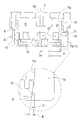
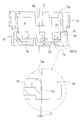
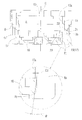
- FIG. 5 is a sectional view taken along line X 1 -X 1 of FIG.
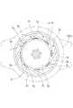
- FIG. 5 is a partial cross-sectional view taken along line YY in FIG. 4.
- FIG. 12 is a sectional view taken along line X 2 -X 2 of FIG.
- the present invention is characterized in part of the inflow nozzles N 1 of the lower inner case K 1, water that has flowed from the case inlet 2 of the lower case 1 therein, the inflow nozzles N 1 of the lower inner case K 1 through, in the interior of the metering chamber R of the lower inner case K 1, after rotating the impeller 12, it is discharged through the outflow nozzle N 2, performs the description up portion for weighing the accumulated flow Since the configuration in which the accumulated rotational speed of the impeller 12 is displayed on a display unit (not shown) is not directly related to the present invention, description of this part is omitted.
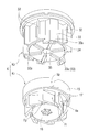
- the lower case 1 includes a case inlet 2 and a case outlet 3, and the interior is separated into an upstream chamber 5 and a downstream chamber 6 by a partition wall 4, and is formed in the partition wall 4.
- the support step 8 on the outer periphery of the lower inner case K 1 faces the insertion opening 7 on the upper surface of the partition wall 4.
- the lower inner case K 1 is accommodated and arranged over both the upstream chamber 5 and the downstream chamber 6.
- an upper inner case (also referred to as a “register box”) K 2 with an integrated display unit (not shown) is disposed, so that the lower inner case K 1
- the top opening is closed.
- the upper part of the lower case 1 above the downstream chamber 6 is an upward projecting portion 1a formed in an annular shape, and the upper case 9 is screwed into the upper projecting portion 1a. Is closed by a lid 11 rotatably connected to the upper case 9 by hinge connection.
- the inside of the lower inner case K 1 is a measuring chamber R, and the impeller 12 is rotatably disposed in the measuring chamber R via a pivot shaft 13.
- the pivot shaft 13 is supported by the shaft support portion 14 of the central portion of the bottom wall portion 16 of the lower inner case K 1.
- the lower inner case K 1 has a substantially cylindrical shape with a bottom, and includes a peripheral wall portion 15 and a bottom wall portion 16.
- the lower inner case K 1 is substantially below the peripheral wall portion 15.
- a plurality of (eight in the embodiment) inflow nozzles N 1 are formed at regular intervals along the circumferential direction in a portion corresponding to the thickness of the peripheral wall 15 in the half.
- a plurality (three in the embodiment) of outflow nozzles N 2 are formed in communication with the inside and outside at regular intervals along the circumferential direction.
- the outflow nozzle N 2 opens upward in the single state of the lower inner case K 1 , but this upward opening is axially directed to the outer peripheral surface of the peripheral wall portion 31 of the upper inner case K 2.
- the lower protrusion 33a of the second rib 33 provided along is fitted and closed.
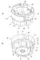
- the inflow nozzle N 1 connects the peripheral wall portion 15 and the bottom wall portion 16 along a direction in which the plurality of nozzle forming bodies 17 having a blade shape are slightly inclined with respect to the tangential direction of the peripheral wall portion 15. It is provided in such a form. As shown in FIGS. 5 and 6, the outer diameter of the bottom wall portion 16 corresponds to the inner diameter of the peripheral wall portion 15.
- the nozzle forming body 17 connects the outer peripheral surface of the bottom wall portion 16 and the lower end portion of the upper half portion of the peripheral wall portion 15, and the inflow nozzle N 1 is an opposing surface of two adjacent nozzle forming bodies 17.
- the upwardly flowing water flow into the measuring chamber R is curved upward guide surfaces Fp and Ft (see FIGS. 2 to 5) having a function of guiding the upward flow into the measuring chamber R.
- a plurality of nozzle forming bodies 17 are provided in the lower half of the peripheral wall portion 15 immediately above the upward flow guide surfaces Fp and Ft so that the thin wall portion remaining only on the inner peripheral side is opened in a square shape.
- the nozzle opening 22 formed by this is provided.
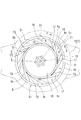
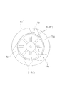
- Example 1 As shown in FIGS. 4-6, a plurality of upward flow guide surface Fp, Ft, rather than the inner circumferential surface 15a of the peripheral wall 15 of the lower both the inner case K 1, dimensions ( Only E 1 ) is arranged on the center side of the lower inner case K 1 . Further, among the plurality of upward flow guide surfaces Fp, only one specific upward flow guide surface Ft arranged at the position farthest from the case inlet 2 of the lower case 1 is the following tapered surface. Yes.
- the upward flow guiding surface Ft lower edge and the lower inner case K 1 center (C) connecting the length (L 1) is the upper end of the upward flow guide surface Ft edge and the lower inner case K 1 the center (C) and length connecting (L 2) slightly shorter than (L 1 ⁇ L 2) be formed on the tapered surface of the inclination angle (theta), this configuration is a feature of the present invention is there.
- All upflow guiding surface Fp rest except for certain upward flow guide surface Ft is parallel with the inner peripheral surface 15a of the peripheral wall 15 of the lower inner case K 1.
- the inner case K includes a lower inner case K 1 described above is disposed directly above the corresponding lower inner case K 1, while closing the upper opening of the lower inner case K 1 , display unit for displaying the accumulated number of rotations of the impeller 12 (not shown) is constituted by the inner case K 2 on the interior.
- display unit for displaying the accumulated number of rotations of the impeller 12 (not shown) is constituted by the inner case K 2 on the interior.
- the plate-like first rib 32 reaching the lower end of the peripheral wall portion 31 and the lower end of the peripheral wall portion 31 are a predetermined length.
- a second rib 33 extending downward is formed in the axial direction at a predetermined interval along the circumferential direction.
- the second rib 33 have a substantially rectangular shape corresponding to the planar shape of the upper opening of the outlet nozzle N 2 of the lower inner case K 1, fitting the positioning of the upper inner case K 2 on the upper surface opening of the lower inner case K 1
- the lower protrusion 33 a of the second rib 33 is formed on the upper opening of the outflow nozzle N 2 of the lower inner case K 1 .
- the upper opening of the lower inner case K 1 is closed by the bottom wall portion 35 of the upper inner case K 2 while being fitted to the portion.
- reference numeral 41 denotes a strainer provided in the case inlet 2 portion of the lower case 1.
- the present invention has a structure corresponding to resin injection molding for preventing “sinking” of the surface and preventing the surface from undulating, and is characterized by the presence of the upward flow guide surface Ft having a tapered surface shape.
- the structure is not directly related.
- the water flow which flowed into the upstream chamber 5 from the case inlet 2 of the lower case 1 is between the peripheral wall portion 15 of the lower inner case K 1 and the lower peripheral wall portion 1b of the lower case 1 (see FIGS. 1 and 4).
- the measuring chamber R through the original nozzle path that is close to the tangential direction of the inflow nozzle N 1 and flows along the circumferential direction (the tangential direction of the peripheral wall 15 of the lower inner case K 1 or the impeller 12).
- the bottom surface of the inflow nozzle N 1 is reached.
- the flow velocity is reduced, and in the portion of the inflow nozzle N 1 far from the case inlet 2 of the lower case 1 among the plurality of inflow nozzles N 1 , the upward flow is guided by the upward flow guide surfaces Fp and Ft. After becoming S 2 , it is accompanied by the tangential flow S 1 passing through the inflow nozzle N 1 and flows into the measuring chamber R of the lower inner case K 1 .
- the upward flow guide surface Ft farthest (separated from) the case inlet 2 of the lower case 1 is formed in the above-described tapered surface, and therefore, when inflow. The fluid resistance is reduced and smoothly flows into the measuring chamber R.
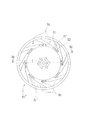
- FIG. 1 A lower inner case K 1 ′ of Embodiment 2 of the present invention is shown in FIG. More the lower inner case K 1 ', out of all the upward flow guiding surface provided on the inner part of the inflow nozzles N 1, continuous far from the case inlet 2 of the lower case 1 (remote) side Only the upward flow guide surface Ft having a curved surface is formed in a tapered shape, and the inclination angle of the tapered surface is determined from the inflow nozzle N 1 farthest from the case inlet 2 of the lower case 1 from the case flow. As it gets closer to the entrance 2, it gradually decreases.
- the above configuration corresponds to the fact that the upward flow S 2 is generated more as it is farther from the case inlet 2 of the lower case 1 in each inflow nozzle N 1 .
- FIG. 4 and FIG. 7 is a irregular drawing was added and direction of the outer peripheral shape and tangential flow S 1 of the lower case 1 to the bottom surface view of the lower inner case K 1, the lower inner case K 1 and the lower case
- the swirl flow that flows between the lower peripheral wall portion 1b and the tangential flow S 1 turns left.
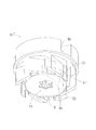
- FIGS. 10 and 11 A lower inner case K 1 ′′ of Embodiment 3 of the present invention is shown in FIGS.
- the upper flow guide surface Ft ′ of the lower inner case K 1 ′′ of the third embodiment is formed in a tapered surface like the upper flow guide surface Ft of the first and second embodiments.
- the overall shape of the taper-shaped upward flow guide surface Ft 2 is a curved surface
- the upper flow guide surface Ft ′ of the lower inner case K 1 ′′ of Example 3 is the overall shape thereof. They differ only in that they are planar.
- the overall shape of all the upward flow guide surfaces Ft ′ formed in the plurality of inflow nozzles N 1 of the lower inner case K 1 ′′ is a flat shape. For this reason, in FIGS. 10 and 11, the upper end edge 51 and the lower end edge 52 of the upward flow guide surface Ft ′, which has a planar shape as a whole and is tapered in a longitudinal sectional view, are straight lines. Appears.
- the inflow nozzle N 1 which has a generally flat upward flow guide surface Ft ′, has a smooth upward flow S 2 flowing upward into the measuring chamber R inside the lower inner case K 1 ′′.
- the inclination angle ( ⁇ ) of the upward flow guide surface Ft is 7.6 °, but the upward flow S 2 is reduced by reducing the fluid resistance of the upward flow S 2.
- 5 to 15 ° is desirable.
- the upward flow S 2 inhibits the tangential flow S 1 that is the original flow, disturbing the natural water flow in the portion of the inflow nozzle N 1 , and the inclination angle This is because when ( ⁇ ) is smaller than 5 °, the original functions of the upward flow guide surfaces Ft and Ft ′ described above cannot be achieved.
- the upper surface of the outflow nozzle N 2 of the lower inner case K 1 is opened, and the upper inner case K 2 Although it is the structure closed by fitting of the downward protrusion part 33a of the 2nd rib 33, as an outflow nozzle, you may form in the through-hole shape by which the upper surface was obstruct
Landscapes
- Physics & Mathematics (AREA)
- Fluid Mechanics (AREA)
- General Physics & Mathematics (AREA)
- Measuring Volume Flow (AREA)
Abstract
L'invention concerne un compteur d'eau de type à boîtiers multiples permettant de réduire la résistance fluide d'écoulement vers le haut s'écoulant dans une chambre de mesure et d'obtenir un débit entrant régulier. À ces fins, chaque buse de débit entrant (N1) est formée de sorte à comporter une surface inférieure ouverte ; et la surface formée par l'exposition de la partie paroi inférieure (16) de la partie arrière d'une buse de débit entrant (N1) sert de surface de guidage pour guider l'écoulement vers le haut (S2) qui traverse les parties paroi inférieure (1c, 16) d'un boîtier inférieur (1) et d'un boîtier interne inférieur (K1) et s'écoule vers le haut au niveau d'une partie buse de débit entrant (N1). La surface de guidage d'écoulement vers le haut (Ft) présente la forme d'une surface courbe ou conique plane dont la longueur du bord inférieur de celle-ci au centre (C) du boîtier interne inférieur (K1) est légèrement plus courte que la longueur allant du bord supérieur de la surface au centre (C) du boîtier interne inférieur (K1).
Applications Claiming Priority (2)
| Application Number | Priority Date | Filing Date | Title |
|---|---|---|---|
| JP2014081595A JP5579948B1 (ja) | 2014-04-11 | 2014-04-11 | 複箱式水道メータ |
| JP2014-081595 | 2014-04-11 |
Publications (1)
| Publication Number | Publication Date |
|---|---|
| WO2015156116A1 true WO2015156116A1 (fr) | 2015-10-15 |
Family
ID=51579134
Family Applications (1)
| Application Number | Title | Priority Date | Filing Date |
|---|---|---|---|
| PCT/JP2015/058807 Ceased WO2015156116A1 (fr) | 2014-04-11 | 2015-03-24 | Compteur d'eau de type à boîtiers multiples |
Country Status (2)
| Country | Link |
|---|---|
| JP (1) | JP5579948B1 (fr) |
| WO (1) | WO2015156116A1 (fr) |
Families Citing this family (2)
| Publication number | Priority date | Publication date | Assignee | Title |
|---|---|---|---|---|
| JP6258187B2 (ja) * | 2014-11-26 | 2018-01-10 | 株式会社 Toshin | 複箱式水道メータ、及びそのインナーケースの組付け方法 |
| JP6320614B1 (ja) * | 2017-12-01 | 2018-05-09 | 株式会社西部水道機器製作所 | 水道メータ |
Citations (4)
| Publication number | Priority date | Publication date | Assignee | Title |
|---|---|---|---|---|
| JPS5164670U (fr) * | 1974-11-18 | 1976-05-21 | ||
| JPS556818U (fr) * | 1978-06-30 | 1980-01-17 | ||
| JPS5644810A (en) * | 1979-05-01 | 1981-04-24 | Ricoh Elemex Corp | Water works meter |
| JP2000234944A (ja) * | 1999-02-17 | 2000-08-29 | Aichi Tokei Denki Co Ltd | 水道メータ |
-
2014
- 2014-04-11 JP JP2014081595A patent/JP5579948B1/ja not_active Expired - Fee Related
-
2015
- 2015-03-24 WO PCT/JP2015/058807 patent/WO2015156116A1/fr not_active Ceased
Patent Citations (4)
| Publication number | Priority date | Publication date | Assignee | Title |
|---|---|---|---|---|
| JPS5164670U (fr) * | 1974-11-18 | 1976-05-21 | ||
| JPS556818U (fr) * | 1978-06-30 | 1980-01-17 | ||
| JPS5644810A (en) * | 1979-05-01 | 1981-04-24 | Ricoh Elemex Corp | Water works meter |
| JP2000234944A (ja) * | 1999-02-17 | 2000-08-29 | Aichi Tokei Denki Co Ltd | 水道メータ |
Also Published As
| Publication number | Publication date |
|---|---|
| JP2015203576A (ja) | 2015-11-16 |
| JP5579948B1 (ja) | 2014-08-27 |
Similar Documents
| Publication | Publication Date | Title |
|---|---|---|
| US9260852B2 (en) | Spiral guiding drain structure | |
| TWI674344B (zh) | 貯存槽、虹吸式排水系統及流出管連接構件(二) | |
| TWI672417B (zh) | 貯存槽、虹吸式排水系統及流出管連接構件(一) | |
| JP5579948B1 (ja) | 複箱式水道メータ | |
| JP3199788U (ja) | 複箱式水道メータ | |
| WO2018045963A1 (fr) | Vanne d'admission d'eau anti-siphon et toilette | |
| KR200437952Y1 (ko) | 정류기를 구비한 수도계량기 | |
| JP6148071B2 (ja) | 複箱式水道メータ | |
| JP2017210930A (ja) | 渦流ポンプ | |
| JP5022511B1 (ja) | 羽根車式水道メータ用インナーケース、羽根車式水道メータ用計量装置、及び、羽根車式水道メータ | |
| CN204298079U (zh) | 一种tds在线检测的探头安装结构及净水器 | |
| JP5454982B2 (ja) | 縦型水道メータ | |
| JP5147099B2 (ja) | 縦型水道メータ | |
| JP4318336B2 (ja) | 水道メータ | |
| JP6222593B1 (ja) | 水道メータ | |
| JP2009279385A5 (fr) | ||
| KR100852914B1 (ko) | 비데의 와류형 분사노즐 | |
| CN215505861U (zh) | 一种进出口流速有角度偏转的阀门滤网结构 | |
| JP6584872B2 (ja) | 膜式ガスメータ | |
| CN208951412U (zh) | 用于燃气热水器的多级节流装置和燃气热水器 | |
| JP6457196B2 (ja) | 膜式ガスメーター | |
| JP6209960B2 (ja) | エアクリーナ | |
| CN209873965U (zh) | 一种多组弯管构成的新型高位水池装置 | |
| JP2017119521A (ja) | 打栓コック及びこれに用いるアダプタ | |
| EP3276312B1 (fr) | Compteur de liquide ayant des ailettes de stabilisation |
Legal Events
| Date | Code | Title | Description |
|---|---|---|---|
| 121 | Ep: the epo has been informed by wipo that ep was designated in this application |
Ref document number: 15776027 Country of ref document: EP Kind code of ref document: A1 |
|
| NENP | Non-entry into the national phase |
Ref country code: DE |
|
| 122 | Ep: pct application non-entry in european phase |
Ref document number: 15776027 Country of ref document: EP Kind code of ref document: A1 |