WO2015156382A1 - 内燃機関用点火装置 - Google Patents
内燃機関用点火装置 Download PDFInfo
- Publication number
- WO2015156382A1 WO2015156382A1 PCT/JP2015/061191 JP2015061191W WO2015156382A1 WO 2015156382 A1 WO2015156382 A1 WO 2015156382A1 JP 2015061191 W JP2015061191 W JP 2015061191W WO 2015156382 A1 WO2015156382 A1 WO 2015156382A1
- Authority
- WO
- WIPO (PCT)
- Prior art keywords
- circuit
- capacitor
- primary
- ignition
- energy input
- Prior art date
- Legal status (The legal status is an assumption and is not a legal conclusion. Google has not performed a legal analysis and makes no representation as to the accuracy of the status listed.)
- Ceased
Links
Images

Classifications
-
- F—MECHANICAL ENGINEERING; LIGHTING; HEATING; WEAPONS; BLASTING
- F02—COMBUSTION ENGINES; HOT-GAS OR COMBUSTION-PRODUCT ENGINE PLANTS
- F02P—IGNITION, OTHER THAN COMPRESSION IGNITION, FOR INTERNAL-COMBUSTION ENGINES; TESTING OF IGNITION TIMING IN COMPRESSION-IGNITION ENGINES
- F02P3/00—Other installations
- F02P3/06—Other installations having capacitive energy storage
- F02P3/08—Layout of circuits
- F02P3/0807—Closing the discharge circuit of the storage capacitor with electronic switching means
-
- F—MECHANICAL ENGINEERING; LIGHTING; HEATING; WEAPONS; BLASTING
- F02—COMBUSTION ENGINES; HOT-GAS OR COMBUSTION-PRODUCT ENGINE PLANTS
- F02P—IGNITION, OTHER THAN COMPRESSION IGNITION, FOR INTERNAL-COMBUSTION ENGINES; TESTING OF IGNITION TIMING IN COMPRESSION-IGNITION ENGINES
- F02P11/00—Safety means for electric spark ignition, not otherwise provided for
-
- F—MECHANICAL ENGINEERING; LIGHTING; HEATING; WEAPONS; BLASTING
- F02—COMBUSTION ENGINES; HOT-GAS OR COMBUSTION-PRODUCT ENGINE PLANTS
- F02P—IGNITION, OTHER THAN COMPRESSION IGNITION, FOR INTERNAL-COMBUSTION ENGINES; TESTING OF IGNITION TIMING IN COMPRESSION-IGNITION ENGINES
- F02P15/00—Electric spark ignition having characteristics not provided for in, or of interest apart from, groups F02P1/00 - F02P13/00 and combined with layout of ignition circuits
- F02P15/10—Electric spark ignition having characteristics not provided for in, or of interest apart from, groups F02P1/00 - F02P13/00 and combined with layout of ignition circuits having continuous electric sparks
-
- F—MECHANICAL ENGINEERING; LIGHTING; HEATING; WEAPONS; BLASTING
- F02—COMBUSTION ENGINES; HOT-GAS OR COMBUSTION-PRODUCT ENGINE PLANTS
- F02P—IGNITION, OTHER THAN COMPRESSION IGNITION, FOR INTERNAL-COMBUSTION ENGINES; TESTING OF IGNITION TIMING IN COMPRESSION-IGNITION ENGINES
- F02P3/00—Other installations
- F02P3/06—Other installations having capacitive energy storage
- F02P3/08—Layout of circuits
- F02P3/0876—Layout of circuits the storage capacitor being charged by means of an energy converter (DC-DC converter) or of an intermediate storage inductance
- F02P3/0884—Closing the discharge circuit of the storage capacitor with semiconductor devices
- F02P3/0892—Closing the discharge circuit of the storage capacitor with semiconductor devices using digital techniques
-
- F—MECHANICAL ENGINEERING; LIGHTING; HEATING; WEAPONS; BLASTING
- F02—COMBUSTION ENGINES; HOT-GAS OR COMBUSTION-PRODUCT ENGINE PLANTS
- F02P—IGNITION, OTHER THAN COMPRESSION IGNITION, FOR INTERNAL-COMBUSTION ENGINES; TESTING OF IGNITION TIMING IN COMPRESSION-IGNITION ENGINES
- F02P15/00—Electric spark ignition having characteristics not provided for in, or of interest apart from, groups F02P1/00 - F02P13/00 and combined with layout of ignition circuits
- F02P15/08—Electric spark ignition having characteristics not provided for in, or of interest apart from, groups F02P1/00 - F02P13/00 and combined with layout of ignition circuits having multiple-spark ignition, i.e. ignition occurring simultaneously at different places in one engine cylinder or in two or more separate engine cylinders
-
- F—MECHANICAL ENGINEERING; LIGHTING; HEATING; WEAPONS; BLASTING
- F02—COMBUSTION ENGINES; HOT-GAS OR COMBUSTION-PRODUCT ENGINE PLANTS
- F02P—IGNITION, OTHER THAN COMPRESSION IGNITION, FOR INTERNAL-COMBUSTION ENGINES; TESTING OF IGNITION TIMING IN COMPRESSION-IGNITION ENGINES
- F02P3/00—Other installations
- F02P3/02—Other installations having inductive energy storage, e.g. arrangements of induction coils
- F02P3/04—Layout of circuits
- F02P3/05—Layout of circuits for control of the magnitude of the current in the ignition coil
-
- F—MECHANICAL ENGINEERING; LIGHTING; HEATING; WEAPONS; BLASTING
- F02—COMBUSTION ENGINES; HOT-GAS OR COMBUSTION-PRODUCT ENGINE PLANTS
- F02P—IGNITION, OTHER THAN COMPRESSION IGNITION, FOR INTERNAL-COMBUSTION ENGINES; TESTING OF IGNITION TIMING IN COMPRESSION-IGNITION ENGINES
- F02P3/00—Other installations
- F02P3/06—Other installations having capacitive energy storage
- F02P3/08—Layout of circuits
- F02P3/0876—Layout of circuits the storage capacitor being charged by means of an energy converter (DC-DC converter) or of an intermediate storage inductance
-
- F—MECHANICAL ENGINEERING; LIGHTING; HEATING; WEAPONS; BLASTING
- F02—COMBUSTION ENGINES; HOT-GAS OR COMBUSTION-PRODUCT ENGINE PLANTS
- F02P—IGNITION, OTHER THAN COMPRESSION IGNITION, FOR INTERNAL-COMBUSTION ENGINES; TESTING OF IGNITION TIMING IN COMPRESSION-IGNITION ENGINES
- F02P9/00—Electric spark ignition control, not otherwise provided for
- F02P9/002—Control of spark intensity, intensifying, lengthening, suppression
- F02P9/007—Control of spark intensity, intensifying, lengthening, suppression by supplementary electrical discharge in the pre-ionised electrode interspace of the sparking plug, e.g. plasma jet ignition
Definitions
- the present disclosure relates to an ignition device used for an internal combustion engine (engine), and particularly to a technique for continuing spark discharge.
- a technique is known that uses a device that continues discharge by injecting discharge energy into an ignition coil after starting spark discharge by a main ignition circuit. Thereby, the discharge continuation time after the start of discharge is extended, and stable ignition is aimed at.
- main ignition circuit As a technology to reduce the burden on the spark plug, suppress unnecessary power consumption, and continue spark discharge, spark discharge (referred to as main ignition circuit) is started by a well-known ignition circuit (referred to as main ignition circuit). Before the lamp disappears, electric energy is applied from the negative side of the primary coil toward the battery power supply line, current in the same direction (DC secondary current) flows through the secondary coil, and the spark discharge generated by the main ignition is discharged.
- An “energy input circuit” that is continued for an arbitrary period hereinafter referred to as a discharge duration period
- a discharge duration period An “energy input circuit” that is continued for an arbitrary period (hereinafter referred to as a discharge duration period) has been studied (not a known technique).
- the spark discharge that is continued by the energy input circuit that is, the spark discharge following the main ignition
- continuous spark discharge is referred to as “continuous spark discharge”.
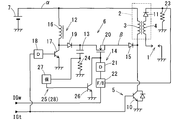
- the ignition device shown in FIG. 5 is a combination of a main ignition circuit 5 that causes main ignition to the spark plug 1 by full tiger operation and an energy input circuit 6.
- the energy input circuit 6 is A booster circuit 12 that boosts the battery voltage; A capacitor 13 for storing electrical energy boosted by the booster circuit 12, and Input energy control means 14 for controlling the secondary current by controlling the electric energy input from the capacitor 13 to the primary coil 3 of the ignition coil 2; Is provided.
- An example of the input energy control means 14 is: Energy input switching means 20 for intermittently supplying an energy input line ⁇ for inputting electric energy from the capacitor 13 to the primary coil 3; An energy input driver circuit 21 for switching the energy input switching means 20 between ON and OFF; A control circuit 22 for maintaining the secondary current at a predetermined target value by controlling the ON / OFF state of the energy input switching means 20 via the energy input driver circuit 21; Is provided.
- the control circuit 22 (I) When the secondary current to be monitored using the secondary current detection resistor 23 falls below the target value, the energy input switching means 20 is turned on to convert a part of the electric energy charged in the capacitor 13 to the primary coil 3. To (Ii) When the secondary current increases from the target value, the energy input switching means 20 is turned off to perform control to interrupt the energy input to the primary coil 3.
- the primary coil 3 When the primary coil 3 is magnetically saturated, the effect of increasing the secondary current is reduced, and feedback control is performed so that the energy input to the primary coil 3 is further increased. As a result, the burden on the energy input switching means 20 and the primary coil 3 is increased, and there is a concern that the energy input switching means 20 and the primary coil 3 may be damaged due to heat generation and thermal runaway.
- the present disclosure has been made in view of the above-described problems, and an object of the present disclosure is to ignite an internal combustion engine in which the primary coil is magnetically saturated by the operation of the energy input circuit, and problems of respective parts due to the magnetic saturation can be avoided. Is in the provision of.
- An ignition device for an internal combustion engine controls electrical energy input from a capacitor to a primary coil based on a capacitor discharge current detected by a primary current detection unit, and controls a primary side
- the maximum value of the capacitor discharge current detected by the current detection means is limited to a value smaller than a predetermined first control value.
- the ignition device for an internal combustion engine provides electrical energy from the capacitor to the primary coil when the capacitor discharge current detected by the primary-side current detection means reaches a predetermined second control value Y2. Stop the input of. Avoiding problems caused by magnetic saturation of the primary coil by stopping the input of electric energy to the primary coil before the primary coil is magnetically saturated based on the detection value of the primary side current detection means. Can do. For this reason, it is possible to avoid damage to the primary coil due to heat generation or thermal runaway, or damage to a part of the energy input circuit (for example, switching means for energy input), and improve the reliability of the internal combustion engine ignition device. be able to.
- Example 3 is a time chart for explaining operations (Examples 1 to 3).
- Example 3 which is a schematic block diagram of the internal combustion engine ignition device.
- Example 4 which is a schematic block diagram of the internal combustion engine ignition device.
- the schematic block diagram of the ignition device for internal combustion engines (reference example: it is not a well-known technique).
- the ignition device is used for a spark ignition engine for running a vehicle, and ignites an air-fuel mixture in a combustion chamber at a predetermined ignition timing.
- An example of the engine is a direct injection engine capable of lean combustion using gasoline as fuel.
- the engine is equipped with an EGR (exhaust gas recirculation) device that returns a part of the exhaust gas to the engine intake side as EGR gas, and further, a swirl that produces a swirling flow of air-fuel mixture (tumble flow, swirl flow, etc.) in the cylinder With flow control means.
- EGR exhaust gas recirculation
- the ignition device in the first embodiment is a DI (abbreviation for direct ignition) type that uses an ignition coil 2 corresponding to each ignition plug 1 of each cylinder.
- This ignition device controls energization of the primary coil 3 of the ignition coil 2 on the basis of instruction signals (ignition signal IGt and discharge continuation signal IGw) given from an ECU (abbreviation of engine control unit) that forms the center of engine control. To do.
- This ignition device controls the spark discharge of the spark plug 1 by controlling the electrical energy generated in the secondary coil 4 of the ignition coil 2 by controlling the energization of the primary coil 3.
- the ECU determines an ignition signal IGt and a discharge continuation signal corresponding to engine parameters (warm-up state, engine speed, engine load, etc.) acquired from various sensors and engine control states (existence of lean combustion, degree of swirl flow, etc.). Generate and output IGw.
- the ignition device mounted on the vehicle A spark plug 1 mounted for each cylinder; An ignition coil 2 mounted for each spark plug 1; A main ignition circuit 5 that performs full-tra (full transistor ignition) operation; An energy input circuit 6 that performs continuous spark discharge; It is configured with.
- the main parts of the main ignition circuit 5 and the energy input circuit 6 are accommodated and arranged in a common case as an “ignition circuit unit”, and are installed in a place different from the spark plug 1 and the ignition coil 2.
- the spark plug 1 is a well-known one, and includes a center electrode connected to one end of the secondary coil 4 and an outer electrode grounded via an engine cylinder head or the like, and is applied from the secondary coil 4. A high voltage causes a spark discharge between the center electrode and the outer electrode.
- the ignition coil 2 is a well-known one and includes a primary coil 3 and a secondary coil 4 having a larger number of turns than the number of turns of the primary coil 3.
- One end of the primary coil 3 is connected to a battery voltage supply line ⁇ that receives power from the positive electrode of the in-vehicle battery 7.
- the other end of the primary coil 3 is grounded via an ignition switching means 10 (for example, a power transistor, a MOS transistor, a thyristor, etc.) of the main ignition circuit 5.
- One end of the secondary coil 4 is connected to the center electrode of the spark plug 1 as described above.
- the other end of the secondary coil 4 is grounded or connected to the battery voltage supply line ⁇ .
- the other end of the secondary coil 4 is connected via a first diode 11 that suppresses generation of an unnecessary secondary voltage when the primary coil 3 is energized, and a secondary current detection resistor 23 described later. An example of grounding is shown.
- the main ignition circuit 5 performs energization control of the primary coil 3 to cause main ignition in the spark plug 1. Specifically, the main ignition circuit 5 turns on the ignition switching means 10 over the ON period of the ignition signal IGt. When the ignition switching means 10 is turned on, the primary coil 3 of the ignition coil 2 is energized. Is done.
- the energy input circuit 6 supplies the secondary coil 4 in the same direction by supplying electric energy from the negative side of the primary coil 3 toward the battery voltage supply line ⁇ during the main ignition caused by the operation of the main ignition circuit 5.
- the secondary current is continuously supplied, and the spark discharge generated by the operation of the main ignition circuit 5 is continued.
- the energy input circuit 6 continues the spark discharge during the operation state in which the ignitability decreases (during lean combustion, generation of strong swirling flow, high EGR rate, low temperature start, etc.)
- a booster circuit 12 that boosts the battery voltage
- a capacitor 13 for storing electrical energy boosted by the booster circuit 12, and Input energy control means 14 for controlling the secondary current by controlling the electric energy input from the capacitor 13 to the primary coil 3
- a second diode 15 that allows current to flow only from the capacitor 13 to the primary coil 3, It is configured with.
- the booster circuit 12 is a chopper type DC-DC converter that boosts a DC voltage, A choke coil 16 having one end connected to the battery voltage supply line ⁇ , A step-up switching means 17 (for example, a field effect transistor, a power transistor, etc.) for intermittently energizing the choke coil 16; A boosting driver circuit 18 for repeatedly turning on and off the boosting switching means 17; A third diode 19 that prevents the electrical energy stored in the capacitor 13 from flowing back to the choke coil 16 side; It is configured with.
- a step-up switching means 17 for example, a field effect transistor, a power transistor, etc.
- the boosting driver circuit 18 is provided so as to repeatedly turn on and off the boosting switching means 17 at a predetermined cycle over a period when the ignition signal IGt is given from the ECU.
- An example of the input energy control unit 14 includes an energy input switching unit 20, an energy input driver circuit 21, and a control circuit 22.
- the energy input switching means 20 is for intermittently connecting an energy input line ⁇ for inputting electric energy from the capacitor 13 to the primary coil 3, and is composed of, for example, a MOS transistor, a power transistor, or the like.
- the energy input driver circuit 21 switches the energy input switching means 20 on and off.
- the control circuit 22 controls the secondary current to a predetermined target value by controlling the ON / OFF state of the energy input switching means 20 via the energy input driver circuit 21. For example, the secondary current is controlled to a predetermined target value by adjusting the ON / OFF duty ratio of the energy input switching means 20.
- the control circuit 22 sets the ON / OFF state of the energy input switching means 20 via the energy input driver circuit 21 so that the secondary current monitored using the secondary current detection resistor 23 maintains a predetermined target range.
- Feedback control The control circuit 22 is not limited to the feedback control, and may be an ON / OFF control of the energy input switching means 20 by open loop control so that the secondary current maintains a predetermined target range. good. Further, the target value of the secondary current during the continuous spark discharge may be constant, or may be changed according to the engine operating state (instruction signal (not shown) given from the ECU).
- the continuous spark discharge can be continued while the discharge continuation signal IGw is continued, high ignitability can be obtained.
- the secondary current is controlled to be substantially constant during the continuous spark discharge, the effect of reducing electrode wear due to a large current can be obtained.
- the secondary current is controlled to be substantially constant, so that unnecessary power consumption can be suppressed and an energy saving effect can be obtained.
- the primary current increases and the primary coil 3 may be magnetically saturated.
- the increase in the secondary current is reduced from the expected value.
- the magnetic saturation of the primary coil 3 increases rapidly.
- the rapid increase of the primary current due to the magnetic saturation of the primary coil 3 is not effective for maintaining the secondary current, and wastes energy, and there is a concern that the circuit and the coil may be destroyed.
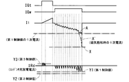
- 2 is a reference example when the primary coil 3 is magnetically saturated without applying the present invention.
- IGt is a high / low signal of the ignition signal IGt
- IGw is a high / low signal of the discharge continuation signal IGw
- I1 is a primary current (current flowing through the primary coil 3).
- IRd is the charge / discharge current of the capacitor 13. In the graph of FIG. 2, the horizontal axes of I1 and IRd indicate zero, and when the capacitor charge / discharge current and the primary current are described, the absolute value is described. .
- the ignition device of the first embodiment is a means for avoiding magnetic saturation of the primary coil 3, A primary side current detection means 24 for detecting a capacitor discharge current supplied from the capacitor 13 to the primary coil 3; A first protection means 25 for preventing magnetic saturation of the primary coil 3 and preventing wasteful power consumption and heat generation by controlling the input state of electric energy from the capacitor 13 to the primary coil 3; Is provided.
- the primary side current detection means 24 is a current detection resistor provided on the earth ground side of the capacitor 13. The charging / discharging current of the capacitor 13 detected by this current detection resistor (the positive side capacitor charging current and the negative side charge current). Capacitor discharge current) is detected.
- the first protection means 25 controls the electric energy supplied from the capacitor 13 to the primary coil 3 based on the capacitor discharge current detected by the primary side current detection means 24, and the primary side current detection means 24
- the detected maximum value of the capacitor discharge current is limited to a value smaller than a predetermined first control value.
- the energy input switching unit 20 is controlled directly or indirectly so that the maximum value of the capacitor discharge current detected by the primary side current detection unit 24 does not exceed the first control value Y1.
- the primary current when the capacitor discharge current is the first control value Y1 is obtained in advance by a test or the like, and is set to, for example, about 50 to 90% of the saturation current value X from the result. .
- the first protection means 25 of this embodiment is OFF switching means 26 (bipolar transistor, field effect transistor, etc.) for forcibly turning off the energy input switching means 20;
- a protection circuit 27 for controlling the ON-OFF state of the switching means for OFF 26 so that the capacitor discharge current detected by the primary-side current detection means 24 does not exceed the first control value Y1, It is configured with.
- the maximum value (absolute value) of the primary current I1 based on the capacitor discharge current IRd detected by the primary current detection means 24, as shown by the solid line A in FIG. can be limited to a value smaller than the saturation current value X.
- the malfunction that the primary coil 3 is magnetically saturated by the operation of the energy input circuit 6 can be avoided.
- the energy charging switching means 20 and the primary coil 3 caused by magnetic saturation of the primary coil 3 can be prevented from being damaged due to thermal runaway or heat generation, and the reliability of the ignition device equipped with the energy charging circuit 6 can be avoided.
- the primary side current detection means 24 of the first embodiment is a current detection resistor provided on the earth ground side of the capacitor 13. Since the current load is small on the earth ground side of the capacitor 13, the current detection resistor can be reduced in size. For this reason, the enlargement and cost increase of the energy input circuit 6 can be avoided, and the size reduction of the ignition circuit unit and the cost increase of the ignition device can be avoided.
- the input energy control unit 14 and the first protection unit 25 are provided independently. However, the input energy control unit 14 and the first protection unit 25 may be shared. That is, the switching means for OFF 26 may be eliminated, and the energy charging switching means 20 may be directly controlled to avoid magnetic saturation of the primary coil 3.
- Example 2 A second embodiment will be described with reference to FIGS. Since the basic configuration of the second embodiment is the same as that of the first embodiment, the drawing of the second embodiment uses the drawing of the first embodiment. In the following embodiments, the same reference numerals as those in the first embodiment indicate the same functional objects.
- the energy input switching unit 20 is controlled so that the primary coil 3 is not magnetically saturated is shown.
- the second embodiment when the primary current approaches the saturation current value X, the input of electrical energy to the primary coil 3 is stopped to avoid magnetic saturation of the primary coil 3. .
- Primary side current detection means 24 similar to that in the first embodiment, A second protection means 28 for avoiding magnetic saturation of the primary coil 3 by cutting the energy input line ⁇ when the primary current approaches the saturation current value X; Is provided.
- the second protection unit 28 inputs electric energy from the capacitor 13 to the primary coil 3. Stop.
- the energy input line ⁇ is disconnected when the capacitor discharge current detected by the primary side current detection means 24 reaches the second control value Y2.
- the primary current when the capacitor discharge current is the second control value Y2 is obtained in advance by a test or the like, and is set to, for example, about 60 to 100% of the saturation current value X from the result. .
- the second protective means 28 of this embodiment has the same basic configuration as the first protective means 25 of the first embodiment, OFF switching means 26 for forcibly turning off the energy input switching means 20; A protection circuit that forcibly turns off the energy input switching means 20 by turning on the OFF switching means 26 when the capacitor discharge current detected by the primary current detection means 24 reaches the second control value Y2. 27, It is configured with.
- the energy input switching means 20 and the primary coil 3 caused by magnetic saturation of the primary coil 3 can be reliably avoided from being damaged due to thermal runaway or heat generation.
- the reliability of the ignition device equipped with 6 can be improved.
- the input energy control unit 14 and the second protection unit 28 are provided independently. However, the input energy control unit 14 and the second protection unit 28 may be shared. That is, the magnetic switching may be avoided by eliminating the OFF switching means 26 and switching the energy input switching means 20 to the OFF state.
- the energy input switching means 20 is turned off as the means for stopping the input of electric energy.
- the output stop switching means shown in the fourth embodiment which will be described later may be turned off. good.
- the first embodiment and the second embodiment may be combined.
- the protection circuit 27 makes a failure determination of the energy input circuit 6 based on the capacitor discharge current or the capacitor charge current detected by the primary side current detection means 24, and stops the energy input circuit 6 when the failure is determined.
- a failure determination signal IGf is output to the ECU to notify the ECU of the occurrence of the failure.
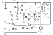
- Example 3 The point of Example 3 is (A) turning off the power supply unit to the booster circuit 12 at the time of failure determination; (B) performing failure determination of the energy input circuit 6 based on the capacitor discharge current detected by the primary side current detection means 24; (C) performing failure determination of the energy input circuit 6 based on the capacitor charging current detected by the primary side current detection means 24; It is.
- An operation stop switching means 31 for example, a normally ON type relay switch, a semiconductor switch, etc. for switching ON / OFF a boost power supply line ⁇ for applying a battery voltage to the booster circuit 12;
- An operation stop drive circuit 32 capable of switching the operation stop switching means 31 to an OFF state; Is provided.
- the operation stop switching means 31 When the protection circuit 27 detects a failure of the energy input circuit 6, the operation stop switching means 31 is switched to the OFF state via the operation stop drive circuit 32 to stop the energy input circuit 6. Further, when the failure determination of the energy input circuit 6 is performed, the protection circuit 27 switches the operation stop switching means 31 to the OFF state and simultaneously outputs a failure determination signal IGf to the ECU to notify the ECU of the occurrence of the failure.
- the ECU upon receiving the failure determination signal IGf from the protection circuit 27, the ECU turns on a lamp or the like to notify the occupant that a failure has occurred and stops the super lean burn operation of the engine.
- the ignitability by only the main ignition is improved, and retreat traveling is possible.
- the protection circuit 27 determines the failure of the energy input circuit 6 based on the capacitor discharge current detected by the primary side current detection means 24.
- the protection circuit 27 (I) When the capacitor discharge current detected by the primary current detection means 24 reaches the second control value Y2, (Ii) When the capacitor discharge current reaches the second control value Y2 continuously for a predetermined number of times, (Iii) When the capacitor discharge current reaches the second control value Y2 continuously for a predetermined time, When a plurality of conditions are established in any one of these or any combination, a failure of the energy input circuit 6 is determined. When the failure determination is made, the protection circuit 27 switches the operation stop switching means 31 to the OFF state and outputs a failure determination signal IGf to the ECU as described above.
- the protection circuit 27 determines the failure of the energy input circuit 6 based on the capacitor charging current detected by the primary side current detection unit 24.
- the protection circuit 27 (I) When the capacitor charging current does not reach the predetermined third control value Y3 during the period in which the booster circuit 12 is performing the boosting operation (output period of the ignition signal IGt), (Ii) When the capacitor charging current does not reach the third control value Y3 continuously a predetermined number of times, (Iii) When the capacitor charging current does not reach the third control value Y3 continuously for a predetermined time, When a plurality of conditions are satisfied in any one or any combination of the above, failure of the booster circuit 12 is determined. When the failure determination is made, the protection circuit 27 switches the operation stop switching means 31 to the OFF state and outputs a failure determination signal IGf to the ECU as described above.
- the ignition device determines the failure of the energy input circuit 6 based on the capacitor charging current or the capacitor discharging current detected by the primary side current detecting unit 24.
- the protection circuit 27 (A) When the energy input switching means 20 is short-circuited, (B) When the discharge continuation signal IGw is fixed to ON (Hi fixed), (C) When the switching means 17 of the booster circuit 12 or the booster coil 16 is opened or grounded and malfunctions, etc. When detecting that the capacitor charging current or the capacitor discharging current exceeds the second control value Y2 or not reaching the third control value Y3, the operation stop switching means 31 is switched to the OFF state to The closing circuit 6 is stopped.
- the energy input circuit 6 is stopped, so that the influence of the failure of the energy input circuit 6 is affected by another device (an ECU or fuel that shares a power source).
- another device an ECU or fuel that shares a power source.
- the concern over the injection device and the like can be eliminated, and the reliability of the ignition device can be improved.
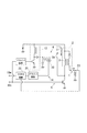
- Embodiment 4 will be described with reference to FIG.
- the power supply to the booster circuit 12 is stopped by disconnecting the booster power supply line ⁇ when determining the failure of the protection circuit 27 has been described.
- the energy input line ⁇ is cut to stop the energy input to the primary coil 3.
- the ignition device of Example 4 is An output stop switching means 33 for turning on and off the energy input line ⁇ between the energy input switching means 20 and the primary coil 3 (for example, a MOS transistor, a power transistor, a normally ON relay switch, etc.); An output stop drive circuit 34 that can switch the output stop switching means 33 to an OFF state.
- An output stop switching means 33 for turning on and off the energy input line ⁇ between the energy input switching means 20 and the primary coil 3 (for example, a MOS transistor, a power transistor, a normally ON relay switch, etc.);
- An output stop drive circuit 34 that can switch the output stop switching means 33 to an OFF state.
- the protection circuit 27 (I) When the failure of the energy input circuit 6 is determined, the output stopping switching means 33 is switched to the OFF state and a failure determination signal IGf is output to the ECU. (Ii) When a failure of the booster circuit 12 is detected, a failure determination signal IGf is output to the ECU and the booster driver circuit 18 is stopped to stop the boosting operation. By providing in this way, the same effect as in the third embodiment can be obtained. Further, in the fourth embodiment, the energy input line ⁇ is disconnected at the time of failure determination without waiting for the operation to be continued due to the residual charge after the power is turned off as compared with the third embodiment. That is, the input of electrical energy to the primary coil 3 can be stopped without waiting for the end of the discharge of the capacitor 13 when determining the failure. For this reason, the safety reliability of the ignition device can be further improved.
- the output stop switching means 33 and the output stop drive circuit 34 may be mounted independently, or a cylinder selection means for selecting the ignition coil 2 as the energy input destination is used. May be.
- the primary side current detection unit 24 current detection resistor
- the position where the primary side current detection unit 24 is provided is not limited. It suffices if the current flowing through the energy input line ⁇ (current supplied from the energy input circuit 6 to the primary coil 3) or the like can be detected.
- the ignition device of the present disclosure is used for a gasoline engine.
- the present invention is applied to an engine using ethanol fuel or mixed fuel. You may do it.
- ignitability can be improved by continuous spark discharge even when used in an engine in which poor fuel may be used.
- the above embodiment shows an example in which the ignition device of the present disclosure is used for a lean burn engine capable of lean burn (lean burn combustion) operation and the ignitability at the lean burn where the ignitability is deteriorated is improved by continuous spark discharge.
- lean burn lean burn combustion
- the ignitability at the lean burn where the ignitability is deteriorated is improved by continuous spark discharge.
- it since it is possible to improve ignitability by continuous spark discharge even in a combustion state different from lean combustion, it is not limited to application to lean burn engines, and is used for engines that do not perform lean combustion. May be.
- the present invention may be applied to a high EGR engine (an engine capable of increasing the return rate of exhaust gas returned to the engine as EGR gas) to generate continuous spark discharge at high EGR, thereby improving ignitability.
- continuous spark discharge may be performed at a low engine temperature at which the ignitability decreases to improve the ignitability at a low engine temperature.
- the ignition device of the present disclosure is used for a direct injection engine that directly injects fuel into the combustion chamber.
- a port injection type that injects fuel to the intake upstream side (inside the intake port) of the intake valve. It may be used for other engines.
- the ignition device of the present disclosure is used for an engine that actively generates a swirling flow (such as a tumble flow or a swirl flow) in a cylinder.
- a swirling flow such as a tumble flow or a swirl flow
- it may be used for an engine having no swirl flow control means (tumble flow control valve, swirl flow control valve, etc.).
- the present disclosure is applied to a DI type ignition device.
- the present disclosure is applied to an ignition device of a single cylinder engine (for example, a motorcycle or the like) in which the ignition coil 2 is mounted at a position away from the ignition plug 1.
- the invention may be applied.
- the main ignition circuit 5 may be a circuit that can perform main ignition by controlling energization of the primary coil 3, and an ignition circuit other than a full-trailer such as a CDI ignition circuit may be used.
Landscapes
- Engineering & Computer Science (AREA)
- Chemical & Material Sciences (AREA)
- Combustion & Propulsion (AREA)
- Mechanical Engineering (AREA)
- General Engineering & Computer Science (AREA)
- Ignition Installations For Internal Combustion Engines (AREA)
Abstract
コンデンサ13のアース接地側に設けた1次側電流検出手段24によって検出されるコンデンサ13の放電電流の最大値が予め1次コイル3の磁気飽和から求めた第1制御値Y1を超えないように、エネルギ投入用スイッチング手段20のON-OFF状態をコントロールする。これにより、1次コイル3の磁気飽和を回避することができ、エネルギ投入回路6を搭載する点火装置の信頼性を高めることができる。
Description
本開示は、内燃機関(エンジン)に用いられる点火装置に関し、特に火花放電の継続技術に関する。
通常の点火装置(主点火装置)に加えて、主点火回路によって火花放電を開始させた後、点火コイルに放電エネルギを投入することで、放電を継続させる装置を用いる技術が知られている。これにより、放電開始後の放電継続時間を延ばし、安定した着火を図っている。
点火プラグの負担を軽減し、無駄な電力消費を抑えて、火花放電を継続させる技術として、周知の点火回路(主点火回路と称す)によって火花放電(主点火と称す)を開始させ、主点火が消える前に1次コイルのマイナス側からバッテリ電力供給ラインに向けて電気エネルギを投入して2次コイルに同一方向の電流(直流の2次電流)を流し、主点火で生じた火花放電を任意の期間(以下、放電継続期間)に亘って継続させる「エネルギ投入回路」が検討されている(公知技術ではない)。
なお、以下では、エネルギ投入回路により継続させる火花放電(即ち、主点火に続く火花放電)を「継続火花放電」と称する。
なお、以下では、エネルギ投入回路により継続させる火花放電(即ち、主点火に続く火花放電)を「継続火花放電」と称する。
ここで、理解補助の目的で、エネルギ投入回路を用いた新規な点火装置の代表例を図5に基づいて説明する。なお、図5に用いる符合は、後述する「実施例」と同一機能物に同一符合を付したものである。
図5に示す点火装置は、フルトラ作動によって点火プラグ1に主点火を生じさせる主点火回路5と、エネルギ投入回路6とを組み合わせたものである。
エネルギ投入回路6は、
・バッテリ電圧を昇圧させる昇圧回路12と、
・この昇圧回路12で昇圧した電気エネルギーを蓄えるコンデンサ13と、
・コンデンサ13から点火コイル2の1次コイル3に投入される電気エネルギを制御することで、2次電流をコントロールする投入エネルギ制御手段14と、
を備える。
エネルギ投入回路6は、
・バッテリ電圧を昇圧させる昇圧回路12と、
・この昇圧回路12で昇圧した電気エネルギーを蓄えるコンデンサ13と、
・コンデンサ13から点火コイル2の1次コイル3に投入される電気エネルギを制御することで、2次電流をコントロールする投入エネルギ制御手段14と、
を備える。
投入エネルギ制御手段14の一例は、
・コンデンサ13から1次コイル3へ電気エネルギーの投入を行うエネルギ投入ラインβを断続させるエネルギ投入用スイッチング手段20と、
・このエネルギ投入用スイッチング手段20をON-OFF切り替えするエネルギ投入用ドライバ回路21と、
・このエネルギ投入用ドライバ回路21を介してエネルギ投入用スイッチング手段20のON-OFF状態を制御することで2次電流を所定の目標値に維持するコントロール回路22と、
を備える。
・コンデンサ13から1次コイル3へ電気エネルギーの投入を行うエネルギ投入ラインβを断続させるエネルギ投入用スイッチング手段20と、
・このエネルギ投入用スイッチング手段20をON-OFF切り替えするエネルギ投入用ドライバ回路21と、
・このエネルギ投入用ドライバ回路21を介してエネルギ投入用スイッチング手段20のON-OFF状態を制御することで2次電流を所定の目標値に維持するコントロール回路22と、
を備える。
コントロール回路22は、エネルギ投入回路6の作動中(具体的には、放電継続信号IGwのON中)に、
(i)2次電流検出抵抗23を用いてモニターする2次電流が目標値より低下するとエネルギ投入用スイッチング手段20をONすることでコンデンサ13に充電された電気エネルギの一部を1次コイル3に投入し、
(ii)2次電流が目標値より増加するとエネルギ投入用スイッチング手段20をOFFすることで1次コイル3へのエネルギ投入を中断する制御を実施する。
(i)2次電流検出抵抗23を用いてモニターする2次電流が目標値より低下するとエネルギ投入用スイッチング手段20をONすることでコンデンサ13に充電された電気エネルギの一部を1次コイル3に投入し、
(ii)2次電流が目標値より増加するとエネルギ投入用スイッチング手段20をOFFすることで1次コイル3へのエネルギ投入を中断する制御を実施する。
本発明者らは、この過程において下記の問題点を見出した。
(問題点)
エネルギ投入回路6の作動中に、エンジンの気筒内に生じる強い気流等によって火花放電が流され、火花放電長が伸張して2次電流が減少する状態が継続すると、2次電流のフィードバック制御によりエネルギ投入用スイッチング手段20のON時間が長くなる。
エネルギ投入用スイッチング手段20のON時間が長くなる場合には、エネルギ投入時の1次電流が増えて1次コイル3が磁気飽和する可能性がある。
(問題点)
エネルギ投入回路6の作動中に、エンジンの気筒内に生じる強い気流等によって火花放電が流され、火花放電長が伸張して2次電流が減少する状態が継続すると、2次電流のフィードバック制御によりエネルギ投入用スイッチング手段20のON時間が長くなる。
エネルギ投入用スイッチング手段20のON時間が長くなる場合には、エネルギ投入時の1次電流が増えて1次コイル3が磁気飽和する可能性がある。
1次コイル3が磁気飽和すると、2次電流を増加させる効果が減り、更に1次コイル3へのエネルギ投入が増加するようにフィードバック制御される。その結果、エネルギ投入用スイッチング手段20や1次コイル3の負担が大きくなり、発熱や熱暴走によってエネルギ投入用スイッチング手段20や1次コイル3が破損する懸念がある。
本開示は、上記問題点に鑑みてなされたものであり、その目的は、エネルギ投入回路の作動によって1次コイルが磁気飽和し、磁気飽和に起因する各部の不具合を回避できる内燃機関用点火装置の提供にある。
本開示の第1態様にかかる内燃機関用点火装置は、1次側電流検出手段によって検出されるコンデンサ放電電流に基づいてコンデンサから1次コイルに投入される電気エネルギをコントロールして、1次側電流検出手段によって検出されるコンデンサ放電電流の最大値を所定の第1制御値より小さい値に制限する。
1次側電流検出手段の検出値に基づいて1次コイルに投入される電気エネルギを、予め設定した所定の値内にコントロールすることで、1次コイルが磁気飽和する不具合を回避することができる。このため、発熱や熱暴走による1次コイルの破損や、エネルギ投入回路の一部(例えば、エネルギ投入用スイッチング手段等)の破損を回避することができ、内燃機関用点火装置の信頼性を高めることができる。
1次側電流検出手段の検出値に基づいて1次コイルに投入される電気エネルギを、予め設定した所定の値内にコントロールすることで、1次コイルが磁気飽和する不具合を回避することができる。このため、発熱や熱暴走による1次コイルの破損や、エネルギ投入回路の一部(例えば、エネルギ投入用スイッチング手段等)の破損を回避することができ、内燃機関用点火装置の信頼性を高めることができる。
本開示の第2態様にかかる内燃機関用点火装置は、1次側電流検出手段によって検出されるコンデンサ放電電流が所定の第2制御値Y2に達した際にコンデンサから1次コイルへの電気エネルギの投入を停止させる。
1次側電流検出手段の検出値に基づいて1次コイルが磁気飽和する前に1次コイルへの電気エネルギの投入を停止することで、1次コイルの磁気飽和に起因する不具合を回避することができる。このため、発熱や熱暴走による1次コイルの破損や、エネルギ投入回路の一部(例えば、エネルギ投入用スイッチング手段等)の破損を回避することができ、内燃機関用点火装置の信頼性を高めることができる。
1次側電流検出手段の検出値に基づいて1次コイルが磁気飽和する前に1次コイルへの電気エネルギの投入を停止することで、1次コイルの磁気飽和に起因する不具合を回避することができる。このため、発熱や熱暴走による1次コイルの破損や、エネルギ投入回路の一部(例えば、エネルギ投入用スイッチング手段等)の破損を回避することができ、内燃機関用点火装置の信頼性を高めることができる。
以下において「発明を実施するための形態」を詳細に説明する。
本開示の具体的な一例(実施例)を図面に基づき説明する。なお、以下の「実施例」は具体的な一例を開示するものであり、本発明が「実施例」に限定されないことは言うまでもない。
[実施例1]
図1、図2を参照して実施例1を説明する。
この実施例1における点火装置は、車両走行用の火花点火エンジンに用いられるものであり、所定の点火タイミングで燃焼室内の混合気に点火を行うものである。なお、エンジンの一例は、ガソリンを燃料とする希薄燃焼(リーンバーン燃焼)が可能な直噴式エンジンである。そのエンジンは、排気ガスの一部をEGRガスとしてエンジン吸気側へ戻すEGR(排気再循環)装置を搭載し、さらに気筒内に混合気の旋回流(タンブル流やスワール流等)を生じさせる旋回流コントロール手段を備える。
図1、図2を参照して実施例1を説明する。
この実施例1における点火装置は、車両走行用の火花点火エンジンに用いられるものであり、所定の点火タイミングで燃焼室内の混合気に点火を行うものである。なお、エンジンの一例は、ガソリンを燃料とする希薄燃焼(リーンバーン燃焼)が可能な直噴式エンジンである。そのエンジンは、排気ガスの一部をEGRガスとしてエンジン吸気側へ戻すEGR(排気再循環)装置を搭載し、さらに気筒内に混合気の旋回流(タンブル流やスワール流等)を生じさせる旋回流コントロール手段を備える。
この実施例1における点火装置は、各気筒の点火プラグ1ごとに対応した点火コイル2を用いるDI(ダイレクト・イグニッションの略)タイプである。
この点火装置は、エンジン制御の中枢を成すECU(エンジン・コントロール・ユニットの略)から与えられる指示信号(点火信号IGtおよび放電継続信号IGw)に基づいて点火コイル2の1次コイル3を通電制御する。この点火装置は、1次コイル3を通電制御することで点火コイル2の2次コイル4に生じる電気エネルギをコントロールして、点火プラグ1の火花放電をコントロールする。
この点火装置は、エンジン制御の中枢を成すECU(エンジン・コントロール・ユニットの略)から与えられる指示信号(点火信号IGtおよび放電継続信号IGw)に基づいて点火コイル2の1次コイル3を通電制御する。この点火装置は、1次コイル3を通電制御することで点火コイル2の2次コイル4に生じる電気エネルギをコントロールして、点火プラグ1の火花放電をコントロールする。
ECUは、各種センサから取得したエンジンパラメータ(暖機状態、エンジン回転速度、エンジン負荷等)やエンジンの制御状態(希薄燃焼の有無、旋回流の程度等)に応じた点火信号IGtおよび放電継続信号IGwを生成して出力する。
車両に搭載される点火装置は、
・各気筒毎に搭載される点火プラグ1と、
・各点火プラグ1毎に搭載される点火コイル2と、
・フルトラ(フルトランジスターイグニッション)作動を行う主点火回路5と、
・継続火花放電を行うエネルギ投入回路6と、
を備えて構成される。
・各気筒毎に搭載される点火プラグ1と、
・各点火プラグ1毎に搭載される点火コイル2と、
・フルトラ(フルトランジスターイグニッション)作動を行う主点火回路5と、
・継続火花放電を行うエネルギ投入回路6と、
を備えて構成される。
なお、主点火回路5とエネルギ投入回路6の主要部は、「点火回路ユニット」として共通のケース内に収容配置されて、点火プラグ1や点火コイル2とは異なる場所に設置される。
点火プラグ1は、周知なものであり、2次コイル4の一端に接続される中心電極と、エンジンのシリンダヘッド等を介してアース接地される外側電極とを備え、2次コイル4から印加される高電圧により中心電極と外側電極との間で火花放電を発生させる。
点火コイル2は、周知なものであり、1次コイル3と、この1次コイル3の巻数より多くの巻数を有する2次コイル4とを備える。
1次コイル3の一端は、車載バッテリ7のプラス電極から電力の供給を受けるバッテリ電圧供給ラインαに接続される。
1次コイル3の他端側は、主点火回路5の点火用スイッチング手段10(例えば、パワートランジスタ、MOS型トランジスタ、サイリスタ等)を介してアース接地される。
1次コイル3の一端は、車載バッテリ7のプラス電極から電力の供給を受けるバッテリ電圧供給ラインαに接続される。
1次コイル3の他端側は、主点火回路5の点火用スイッチング手段10(例えば、パワートランジスタ、MOS型トランジスタ、サイリスタ等)を介してアース接地される。
2次コイル4の一端は、上述したように点火プラグ1の中心電極に接続される。
2次コイル4の他端は、アース接地されるか、あるいはバッテリ電圧供給ラインαに接続される。なお、図1は、2次コイル4の他端が、1次コイル3の通電時に不要な2次電圧の発生を抑制する第1ダイオード11と、後述する2次電流検出抵抗23とを介してアース接地される例を示す。
2次コイル4の他端は、アース接地されるか、あるいはバッテリ電圧供給ラインαに接続される。なお、図1は、2次コイル4の他端が、1次コイル3の通電時に不要な2次電圧の発生を抑制する第1ダイオード11と、後述する2次電流検出抵抗23とを介してアース接地される例を示す。
主点火回路5は、1次コイル3の通電制御を行って点火プラグ1に主点火を生じさせる。具体的に主点火回路5は、点火信号IGtのON期間に亘って点火用スイッチング手段10をONするものであり、点火用スイッチング手段10がONすることで点火コイル2の1次コイル3が通電される。
エネルギ投入回路6は、主点火回路5の作動によって生じた主点火中に1次コイル3のマイナス側からバッテリ電圧供給ラインαへ向けて電気エネルギを投入することで、2次コイル4に同一方向の2次電流を継続して流し、主点火回路5の作動によって生じた火花放電を継続させる。
具体的にエネルギ投入回路6は、着火性が低下する運転状態の時(希薄燃焼時、強旋回流の発生時、高EGR率時、低温始動時など)に火花放電の継続を行って混合気の着火性を高めるものであり、
・バッテリ電圧を昇圧させる昇圧回路12と、
・この昇圧回路12にて昇圧した電気エネルギを蓄えるコンデンサ13と、
・コンデンサ13から1次コイル3に投入される電気エネルギを制御することで、2次電流をコントロールする投入エネルギ制御手段14と、
・コンデンサ13から1次コイル3のみへ電流を流す第2ダイオード15と、
を備えて構成される。
・バッテリ電圧を昇圧させる昇圧回路12と、
・この昇圧回路12にて昇圧した電気エネルギを蓄えるコンデンサ13と、
・コンデンサ13から1次コイル3に投入される電気エネルギを制御することで、2次電流をコントロールする投入エネルギ制御手段14と、
・コンデンサ13から1次コイル3のみへ電流を流す第2ダイオード15と、
を備えて構成される。
昇圧回路12は、直流電圧を昇圧するチョッパー型のDC-DCコンバータであり、
・一端がバッテリ電圧供給ラインαに接続されたチョークコイル16と、
・このチョークコイル16の通電状態を断続する昇圧用スイッチング手段17(例えば、電界効果型トランジスタ、パワートランジスタ等)と、
・この昇圧用スイッチング手段17を繰り返しON-OFFさせる昇圧用ドライバ回路18と、
・コンデンサ13に蓄えた電気エネルギがチョークコイル16側へ逆流するのを防ぐ第3ダイオード19と、
を備えて構成される。
・一端がバッテリ電圧供給ラインαに接続されたチョークコイル16と、
・このチョークコイル16の通電状態を断続する昇圧用スイッチング手段17(例えば、電界効果型トランジスタ、パワートランジスタ等)と、
・この昇圧用スイッチング手段17を繰り返しON-OFFさせる昇圧用ドライバ回路18と、
・コンデンサ13に蓄えた電気エネルギがチョークコイル16側へ逆流するのを防ぐ第3ダイオード19と、
を備えて構成される。
昇圧用ドライバ回路18は、ECUから点火信号IGtが与えられる期間に亘って昇圧用スイッチング手段17を所定周期で繰り返してON-OFFするように設けられている。
投入エネルギ制御手段14の一例は、エネルギ投入用スイッチング手段20と、エネルギ投入用ドライバ回路21と、コントロール回路22と、を備える。
エネルギ投入用スイッチング手段20は、コンデンサ13から1次コイル3へ電気エネルギーの投入を行うエネルギ投入ラインβを断続させるものであり、例えば、MOS型トランジスタ、パワートランジスタ等で構成される。
エネルギ投入用ドライバ回路21は、このエネルギ投入用スイッチング手段20をON-OFF切り替えする。
コントロール回路22は、エネルギ投入用ドライバ回路21を介してエネルギ投入用スイッチング手段20のON-OFF状態を制御することで2次電流を所定の目標値に制御する。例えば、エネルギ投入用スイッチング手段20のON-OFFのDuty比を調整することで、2次電流を所定の目標値に制御する。
エネルギ投入用スイッチング手段20は、コンデンサ13から1次コイル3へ電気エネルギーの投入を行うエネルギ投入ラインβを断続させるものであり、例えば、MOS型トランジスタ、パワートランジスタ等で構成される。
エネルギ投入用ドライバ回路21は、このエネルギ投入用スイッチング手段20をON-OFF切り替えする。
コントロール回路22は、エネルギ投入用ドライバ回路21を介してエネルギ投入用スイッチング手段20のON-OFF状態を制御することで2次電流を所定の目標値に制御する。例えば、エネルギ投入用スイッチング手段20のON-OFFのDuty比を調整することで、2次電流を所定の目標値に制御する。
コントロール回路22は、2次電流検出抵抗23を用いてモニターした2次電流が所定の目標範囲を維持するようにエネルギ投入用ドライバ回路21を介してエネルギ投入用スイッチング手段20のON-OFF状態をフィードバック制御する。
なお、コントロール回路22は、フィードバック制御に限定するものではなく、2次電流が所定の目標範囲を維持するようにオープンループ制御によってエネルギ投入用スイッチング手段20をON-OFF制御するものであっても良い。また、継続火花放電中における2次電流の目標値は、一定であっても良いし、エンジンの運転状態(ECUから付与される図示しない指示信号)に応じて変更するものであっても良い。
なお、コントロール回路22は、フィードバック制御に限定するものではなく、2次電流が所定の目標範囲を維持するようにオープンループ制御によってエネルギ投入用スイッチング手段20をON-OFF制御するものであっても良い。また、継続火花放電中における2次電流の目標値は、一定であっても良いし、エンジンの運転状態(ECUから付与される図示しない指示信号)に応じて変更するものであっても良い。
(点火装置の作動説明)
ここで、主点火回路5とエネルギ投入回路6の基本作動を説明する。
点火信号IGtがOFFからONへ切り替わると、
(a)点火信号IGtが出力される期間に亘って点火用スイッチング手段10がONされるとともに、
(b)点火信号IGtが出力される期間に亘って昇圧用スイッチング手段17が繰り返してON-OFFして昇圧作動を行い、バッテリ電圧より高く昇圧された電気エネルギがコンデンサ13に蓄えられる。
ここで、主点火回路5とエネルギ投入回路6の基本作動を説明する。
点火信号IGtがOFFからONへ切り替わると、
(a)点火信号IGtが出力される期間に亘って点火用スイッチング手段10がONされるとともに、
(b)点火信号IGtが出力される期間に亘って昇圧用スイッチング手段17が繰り返してON-OFFして昇圧作動を行い、バッテリ電圧より高く昇圧された電気エネルギがコンデンサ13に蓄えられる。
(c)点火信号IGtがONからOFFへ切り替わると、点火用スイッチング手段10がOFFされ、1次コイル3の通電状態が突然遮断される。その結果、1次電流が停止すると同時に1次電圧が立ち上がる。これにより、2次電圧が立ち上がって点火プラグ1に高電圧が印加されて、点火プラグ1において主点火が生じる。
(d)点火プラグ1で主点火が開始された後、2次電流は略三角波形状で減衰する。そして、2次電流が所定の下限電流値(火花放電を維持するための電流値)に低下する前に、ECUが放電継続信号IGwを出力する。
すると、コントロール回路22によってエネルギ投入用スイッチング手段20がON-OFF制御されて、コンデンサ13に蓄えられていた電気エネルギ(電荷)が1次コイル3のマイナス側に投入され、コンデンサ13に蓄えられていたバッテリ電圧より高い電圧の電気エネルギが、1次コイル3のマイナス側からバッテリ電圧供給ラインαに向かって流れる。
すると、コントロール回路22によってエネルギ投入用スイッチング手段20がON-OFF制御されて、コンデンサ13に蓄えられていた電気エネルギ(電荷)が1次コイル3のマイナス側に投入され、コンデンサ13に蓄えられていたバッテリ電圧より高い電圧の電気エネルギが、1次コイル3のマイナス側からバッテリ電圧供給ラインαに向かって流れる。
具体的には、エネルギ投入用スイッチング手段20がONされる毎に1次コイル3のマイナス側からバッテリ電圧供給ラインαに向かって電気エネルギが追加される。その結果、電気エネルギが追加される毎に、主点火後の2次電流と同方向の2次電流が2次コイル4に順次追加して流れる。
このように、コントロール回路22がエネルギ投入用スイッチング手段20をON-OFF制御することで、火花放電を維持可能な程度に2次電流を継続して保持することができる。
このように、コントロール回路22がエネルギ投入用スイッチング手段20をON-OFF制御することで、火花放電を維持可能な程度に2次電流を継続して保持することができる。
このように放電継続信号IGwの継続中は、継続火花放電を継続させることができるため、高い着火性を得るこができる。また、継続火花放電の継続中は2次電流が略一定にコントロールされるため、大電流による電極摩耗の軽減効果を得ることができる。さらに、継続火花放電の継続中は2次電流を略一定にコントロールすることで、無駄な電力消費を抑えて省エネ効果を得ることができる。
(f)そして、放電継続信号IGwがONからOFFへ切り替わると、エネルギ投入用スイッチング手段20がOFF状態に切り替わる。これにより、エネルギ投入回路6が停止し、継続火花放電が終了する。
(実施例1の特徴技術)
エネルギ投入回路6の作動中に、エンジンの気筒内に生じる強い気流等によって点火プラグ1に生じた火花放電が流され、火花放電長が伸張して2次電流が減少する状態が継続すると、2次電流のフィードバック制御によりエネルギ投入用スイッチング手段20のON時間を長くして1次コイル3へのエネルギ投入を増やすようになる。
エネルギ投入回路6の作動中に、エンジンの気筒内に生じる強い気流等によって点火プラグ1に生じた火花放電が流され、火花放電長が伸張して2次電流が減少する状態が継続すると、2次電流のフィードバック制御によりエネルギ投入用スイッチング手段20のON時間を長くして1次コイル3へのエネルギ投入を増やすようになる。
エネルギ投入用スイッチング手段20のON時間が長くなることで、1次電流が増加して1次コイル3は磁気飽和する可能性が出てくる。1次コイル3が磁気飽和すると、2次電流の増加が想定値よりも減少する。すると、フィードバック制御によりエネルギ投入を継続するので1次コイル3の磁気飽和度が急激に増加する。1次コイル3の磁気飽和による1次電流の急激な増加は、2次電流維持には効果が少なく無駄なエネルギ消費となるとともに、回路やコイルの破壊に繋がる懸念がある。なお、図2の一点鎖線A’は、本発明を適用せずに、1次コイル3が磁気飽和する場合の参考例である。
ここで、図2中において、「IGt」は点火信号IGtのハイ/ロー信号、「IGw」は放電継続信号IGwのハイ/ロー信号、「I1」は1次電流(1次コイル3に流れる電流値)、「IRd」はコンデンサ13の充放電電流である。なお、図2のグラフにおいて、I1及びIRdの横軸は、ゼロを示しており、コンデンサ充放電電流、一次電流の大きさを記述しているときは、絶対値の大きさについて記述している。
ここで、図2中において、「IGt」は点火信号IGtのハイ/ロー信号、「IGw」は放電継続信号IGwのハイ/ロー信号、「I1」は1次電流(1次コイル3に流れる電流値)、「IRd」はコンデンサ13の充放電電流である。なお、図2のグラフにおいて、I1及びIRdの横軸は、ゼロを示しており、コンデンサ充放電電流、一次電流の大きさを記述しているときは、絶対値の大きさについて記述している。
この実施例1の点火装置は、1次コイル3の磁気飽和を回避する手段として、
・コンデンサ13から1次コイル3に供給されるコンデンサ放電電流の検出を行う1次側電流検出手段24と、
・コンデンサ13から1次コイル3への電気エネルギの投入状態を制御することで、1次コイル3の磁気飽和を回避し、無駄な電力消費や発熱を防止する第1保護手段25と、
を備える。
・コンデンサ13から1次コイル3に供給されるコンデンサ放電電流の検出を行う1次側電流検出手段24と、
・コンデンサ13から1次コイル3への電気エネルギの投入状態を制御することで、1次コイル3の磁気飽和を回避し、無駄な電力消費や発熱を防止する第1保護手段25と、
を備える。
1次側電流検出手段24は、コンデンサ13のアース接地側に設けられた電流検出抵抗であり、この電流検出抵抗によって検出されるコンデンサ13の充放電電流(プラス側のコンデンサ充電電流とマイナス側のコンデンサ放電電流)を検出する。
第1保護手段25は、1次側電流検出手段24によって検出されるコンデンサ放電電流に基づいてコンデンサ13から1次コイル3に投入される電気エネルギをコントロールして、1次側電流検出手段24によって検出されるコンデンサ放電電流の最大値を、所定の第1制御値より小さい値に制限する。
即ち、この実施例では、1次側電流検出手段24によって検出されるコンデンサ放電電流の最大値が第1制御値Y1を超えないようにエネルギ投入用スイッチング手段20を直接または間接的にコントロールする。なお、コンデンサ放電電流が第1制御値Y1の時の1次電流は、予め試験などにより相関が求められるものであり、その結果から例えば、飽和電流値Xの50~90%程に設定される。
この実施例の第1保護手段25は、
・エネルギ投入用スイッチング手段20を強制的にOFFさせるOFF用スイッチング手段26(バイポーラ型トランジスタ、電界効果型トランジスタ等)と、
・このOFF用スイッチング手段26のON-OFF状態を制御して、1次側電流検出手段24によって検出されるコンデンサ放電電流が、第1制御値Y1を超えないようにコントロールする保護回路27と、
を備えて構成される。
・エネルギ投入用スイッチング手段20を強制的にOFFさせるOFF用スイッチング手段26(バイポーラ型トランジスタ、電界効果型トランジスタ等)と、
・このOFF用スイッチング手段26のON-OFF状態を制御して、1次側電流検出手段24によって検出されるコンデンサ放電電流が、第1制御値Y1を超えないようにコントロールする保護回路27と、
を備えて構成される。
(実施例1の効果1)
エネルギ投入回路6の作動中(即ち、放電継続信号IGwがONする期間)に、1次側電流検出手段24によって検出されたコンデンサ放電電流IRdが第1制御値Y1に達すると、保護回路27がOFF用スイッチング手段26をONして、コントロール回路22の制御状態に関わらずエネルギ投入用スイッチング手段20を強制的にOFFする。続いて、1次側電流検出手段24によって検出されたコンデンサ放電電流IRdが第1制御値Y1より再び少なくなると、保護回路27がOFF用スイッチング手段26をOFFし、エネルギ投入用スイッチング手段20がコントロール回路22によってコントロールされる。
エネルギ投入回路6の作動中(即ち、放電継続信号IGwがONする期間)に、1次側電流検出手段24によって検出されたコンデンサ放電電流IRdが第1制御値Y1に達すると、保護回路27がOFF用スイッチング手段26をONして、コントロール回路22の制御状態に関わらずエネルギ投入用スイッチング手段20を強制的にOFFする。続いて、1次側電流検出手段24によって検出されたコンデンサ放電電流IRdが第1制御値Y1より再び少なくなると、保護回路27がOFF用スイッチング手段26をOFFし、エネルギ投入用スイッチング手段20がコントロール回路22によってコントロールされる。
この第1保護手段25の作動により、図2の実線Aに示すように、1次側電流検出手段24によって検出されたコンデンサ放電電流IRdに基づいて、1次電流I1の最大値(絶対値)を飽和電流値Xよりも小さい値に制限できる。
これにより、エネルギ投入回路6の作動によって1次コイル3が磁気飽和する不具合を回避できる。具体的には、1次コイル3の磁気飽和によって生じるエネルギ投入用スイッチング手段20や1次コイル3の熱暴走や発熱による破損を回避することができ、エネルギ投入回路6を搭載する点火装置の信頼性を高めることができる。
これにより、エネルギ投入回路6の作動によって1次コイル3が磁気飽和する不具合を回避できる。具体的には、1次コイル3の磁気飽和によって生じるエネルギ投入用スイッチング手段20や1次コイル3の熱暴走や発熱による破損を回避することができ、エネルギ投入回路6を搭載する点火装置の信頼性を高めることができる。
(実施例1の効果2)
この実施例1の1次側電流検出手段24は、コンデンサ13のアース接地側に設けられた電流検出抵抗である。コンデンサ13のアース接地側は、電流負担が小さいため、電流検出抵抗を小型化できる。このため、エネルギ投入回路6の大型化やコストアップを回避することができ、点火回路ユニットの小型化や、点火装置のコスト上昇を回避できる。
この実施例1の1次側電流検出手段24は、コンデンサ13のアース接地側に設けられた電流検出抵抗である。コンデンサ13のアース接地側は、電流負担が小さいため、電流検出抵抗を小型化できる。このため、エネルギ投入回路6の大型化やコストアップを回避することができ、点火回路ユニットの小型化や、点火装置のコスト上昇を回避できる。
(実施例1の変形例)
なお、この実施例1では、投入エネルギ制御手段14と第1保護手段25を独立して設ける例を示したが、投入エネルギ制御手段14と第1保護手段25を共通化しても良い。即ち、OFF用スイッチング手段26を廃止し、エネルギ投入用スイッチング手段20を直接制御して1次コイル3の磁気飽和を回避させても良い。
なお、この実施例1では、投入エネルギ制御手段14と第1保護手段25を独立して設ける例を示したが、投入エネルギ制御手段14と第1保護手段25を共通化しても良い。即ち、OFF用スイッチング手段26を廃止し、エネルギ投入用スイッチング手段20を直接制御して1次コイル3の磁気飽和を回避させても良い。
[実施例2]
図1、図2を参照して実施例2を説明する。実施例2は実施例1と基本構成が同じであるため、実施例2の図面は実施例1の図面を流用して用いる。なお、以下の各実施例において、上記実施例1と同一符合は同一機能物を示すものである。
図1、図2を参照して実施例2を説明する。実施例2は実施例1と基本構成が同じであるため、実施例2の図面は実施例1の図面を流用して用いる。なお、以下の各実施例において、上記実施例1と同一符合は同一機能物を示すものである。
上記の実施例1では、1次コイル3が磁気飽和しないようにエネルギ投入用スイッチング手段20をコントロールする例を示した。
これに対し、この実施例2は、1次電流が飽和電流値Xに近づいた際に1次コイル3への電気エネルギの投入を停止して1次コイル3の磁気飽和を回避するものである。
これに対し、この実施例2は、1次電流が飽和電流値Xに近づいた際に1次コイル3への電気エネルギの投入を停止して1次コイル3の磁気飽和を回避するものである。
この実施例2の1次コイル3の磁気飽和を回避する手段として、
・実施例1と同様の1次側電流検出手段24と、
・1次電流が飽和電流値Xに接近した際にエネルギ投入ラインβを切断することで1次コイル3の磁気飽和を回避する第2保護手段28と、
を備える。
・実施例1と同様の1次側電流検出手段24と、
・1次電流が飽和電流値Xに接近した際にエネルギ投入ラインβを切断することで1次コイル3の磁気飽和を回避する第2保護手段28と、
を備える。
第2保護手段28は、1次側電流検出手段24によって検出されるコンデンサ放電電流IRdが所定の第2制御値Y2に達した際に、コンデンサ13から1次コイル3への電気エネルギの投入を停止させる。
即ち、この実施例2では、1次側電流検出手段24によって検出されるコンデンサ放電電流が第2制御値Y2に達した際にエネルギ投入ラインβを切断する。なお、コンデンサ放電電流が第2制御値Y2の時の1次電流は、予め試験などにより相関が求められるものであり、その結果から例えば、飽和電流値Xの60~100%程に設定される。
この実施例の第2保護手段28は、実施例1の第1保護手段25と基本構成が同じであり、
・エネルギ投入用スイッチング手段20を強制的にOFFさせるOFF用スイッチング手段26と、
・1次側電流検出手段24によって検出されるコンデンサ放電電流が、第2制御値Y2に達した際にOFF用スイッチング手段26をONしてエネルギ投入用スイッチング手段20を強制的にOFFさせる保護回路27と、
を備えて構成される。
・エネルギ投入用スイッチング手段20を強制的にOFFさせるOFF用スイッチング手段26と、
・1次側電流検出手段24によって検出されるコンデンサ放電電流が、第2制御値Y2に達した際にOFF用スイッチング手段26をONしてエネルギ投入用スイッチング手段20を強制的にOFFさせる保護回路27と、
を備えて構成される。
(実施例2の効果)
エネルギ投入回路6の作動中(即ち、放電継続信号IGwがONする期間)に、1次側電流検出手段24によって検出されたコンデンサ放電電流が第2制御値Y2に達すると、保護回路27がOFF用スイッチング手段26をONしてエネルギ投入用スイッチング手段20を強制的にOFF状態に切り替える。その結果、1次コイル3への電気エネルギの投入を停止して、1次コイル3が磁気飽和に起因する不具合を回避できる。
エネルギ投入回路6の作動中(即ち、放電継続信号IGwがONする期間)に、1次側電流検出手段24によって検出されたコンデンサ放電電流が第2制御値Y2に達すると、保護回路27がOFF用スイッチング手段26をONしてエネルギ投入用スイッチング手段20を強制的にOFF状態に切り替える。その結果、1次コイル3への電気エネルギの投入を停止して、1次コイル3が磁気飽和に起因する不具合を回避できる。
これにより、1次コイル3が磁気飽和することによって生じる不具合を回避できる。具体的には、実施例1と同様、1次コイル3の磁気飽和によって生じるエネルギ投入用スイッチング手段20や1次コイル3の熱暴走や発熱による破損を確実に回避することができ、エネルギ投入回路6を搭載する点火装置の信頼性を高めることができる。
(実施例2の変形例)
なお、この実施例2では、投入エネルギ制御手段14と第2保護手段28を独立して設ける例を示したが、投入エネルギ制御手段14と第2保護手段28を共通化しても良い。即ち、OFF用スイッチング手段26を廃止し、エネルギ投入用スイッチング手段20をOFF状態に切り替えることで磁気飽和を回避させても良い。
なお、この実施例2では、投入エネルギ制御手段14と第2保護手段28を独立して設ける例を示したが、投入エネルギ制御手段14と第2保護手段28を共通化しても良い。即ち、OFF用スイッチング手段26を廃止し、エネルギ投入用スイッチング手段20をOFF状態に切り替えることで磁気飽和を回避させても良い。
また、この実施例2では、電気エネルギの投入を停止させる手段として、エネルギ投入用スイッチング手段20をOFFさせる例を示したが、後述する実施例4に示す出力停止用スイッチング手段をOFFさせても良い。さらに、実施例1と実施例2を組み合わせても良い。
[実施例3]
図2、図3を参照して実施例3を説明する。
この実施例3の保護回路27は、1次側電流検出手段24によって検出されるコンデンサ放電電流またはコンデンサ充電電流に基づいてエネルギ投入回路6の故障判定を行い、故障判定時にエネルギ投入回路6を停止させるとともに、ECUへ故障判定信号IGfを出力して、ECUに故障発生を知らせるものである。
図2、図3を参照して実施例3を説明する。
この実施例3の保護回路27は、1次側電流検出手段24によって検出されるコンデンサ放電電流またはコンデンサ充電電流に基づいてエネルギ投入回路6の故障判定を行い、故障判定時にエネルギ投入回路6を停止させるとともに、ECUへ故障判定信号IGfを出力して、ECUに故障発生を知らせるものである。
実施例3のポイントは、
(a)故障判定時に昇圧回路12への電力供給部をOFFすること、
(b)1次側電流検出手段24によって検出されるコンデンサ放電電流に基づいてエネルギ投入回路6の故障判定を行うこと、
(c)1次側電流検出手段24によって検出されるコンデンサ充電電流に基づいてエネルギ投入回路6の故障判定を行うこと、
である。
(a)故障判定時に昇圧回路12への電力供給部をOFFすること、
(b)1次側電流検出手段24によって検出されるコンデンサ放電電流に基づいてエネルギ投入回路6の故障判定を行うこと、
(c)1次側電流検出手段24によって検出されるコンデンサ充電電流に基づいてエネルギ投入回路6の故障判定を行うこと、
である。
具体的に、この実施例3は、故障判定時に昇圧回路12への電力供給部をOFFする手段として、
・昇圧回路12にバッテリ電圧を付与する昇圧電源ラインγをON-OFF切替する運転停止用スイッチング手段31(例えば、常ON型のリレースイッチ、半導体スイッチ等)と、
・この運転停止用スイッチング手段31をOFF状態へ切り替え可能な運転停止用ドライブ回路32と、
を備える。
・昇圧回路12にバッテリ電圧を付与する昇圧電源ラインγをON-OFF切替する運転停止用スイッチング手段31(例えば、常ON型のリレースイッチ、半導体スイッチ等)と、
・この運転停止用スイッチング手段31をOFF状態へ切り替え可能な運転停止用ドライブ回路32と、
を備える。
そして、保護回路27が、エネルギ投入回路6の故障を検出した際に、運転停止用ドライブ回路32を介して運転停止用スイッチング手段31をOFF状態に切り替えて、エネルギ投入回路6を停止させる。
また、保護回路27は、エネルギ投入回路6の故障判定を行うと、運転停止用スイッチング手段31をOFF状態に切り替えると同時に、ECUへ故障判定信号IGfを出力して、ECUに故障発生を知らせる。
また、保護回路27は、エネルギ投入回路6の故障判定を行うと、運転停止用スイッチング手段31をOFF状態に切り替えると同時に、ECUへ故障判定信号IGfを出力して、ECUに故障発生を知らせる。
一方、ECUは、保護回路27から故障判定信号IGfを受けると、ランプ等を点灯させて乗員に故障が発生した旨を知らせるとともに、エンジンの超リーンバーン運転を中止して、主点火回路5による主点火のみによる着火性を向上させて、退避走行が可能に設けられている。
次に、1次側電流検出手段24によって検出されるコンデンサ放電電流に基づいて保護回路27がエネルギ投入回路6の故障判定を行う技術を説明する。
保護回路27は、
(i)1次側電流検出手段24によって検出されたコンデンサ放電電流が第2制御値Y2に達した際、
(ii)コンデンサ放電電流が第2制御値Y2に所定回数連続して達する際、
(iii)コンデンサ放電電流が第2制御値Y2に所定時間継続して達する際、
のいずれか、またはそれぞれ任意の組み合わせで複数条件が成立した場合に、エネルギ投入回路6の故障を判定する。
そして、保護回路27は、故障判定した際、上述したように、運転停止用スイッチング手段31をOFF状態に切り替えるとともに、ECUへ故障判定信号IGfを出力する。
保護回路27は、
(i)1次側電流検出手段24によって検出されたコンデンサ放電電流が第2制御値Y2に達した際、
(ii)コンデンサ放電電流が第2制御値Y2に所定回数連続して達する際、
(iii)コンデンサ放電電流が第2制御値Y2に所定時間継続して達する際、
のいずれか、またはそれぞれ任意の組み合わせで複数条件が成立した場合に、エネルギ投入回路6の故障を判定する。
そして、保護回路27は、故障判定した際、上述したように、運転停止用スイッチング手段31をOFF状態に切り替えるとともに、ECUへ故障判定信号IGfを出力する。
続いて、1次側電流検出手段24によって検出されるコンデンサ充電電流に基づいて保護回路27がエネルギ投入回路6の故障判定を行う技術を説明する。
保護回路27は、
(i)昇圧回路12が昇圧作動している期間(点火信号IGtの出力期間)にコンデンサ充電電流が所定の第3制御値Y3に達しない場合、
(ii)コンデンサ充電電流が第3制御値Y3に所定回数連続して達しない場合、
(iii)コンデンサ充電電流が第3制御値Y3に所定時間継続して達しない場合、
のいずれか、またはそれぞれ任意の組み合わせで複数条件が成立した場合に、昇圧回路12の故障を判定する。
そして、保護回路27は、故障判定した際、上述したように、運転停止用スイッチング手段31をOFF状態に切り替えるとともに、ECUへ故障判定信号IGfを出力する。
保護回路27は、
(i)昇圧回路12が昇圧作動している期間(点火信号IGtの出力期間)にコンデンサ充電電流が所定の第3制御値Y3に達しない場合、
(ii)コンデンサ充電電流が第3制御値Y3に所定回数連続して達しない場合、
(iii)コンデンサ充電電流が第3制御値Y3に所定時間継続して達しない場合、
のいずれか、またはそれぞれ任意の組み合わせで複数条件が成立した場合に、昇圧回路12の故障を判定する。
そして、保護回路27は、故障判定した際、上述したように、運転停止用スイッチング手段31をOFF状態に切り替えるとともに、ECUへ故障判定信号IGfを出力する。
(実施例3の効果)
実施例3の点火装置は、上述したように、1次側電流検出手段24によって検出されるコンデンサ充電電流またはコンデンサ放電電流に基づいてエネルギ投入回路6の故障判定を行う。
具体的には、保護回路27は、
(a)エネルギ投入用スイッチング手段20がショート故障した場合、
(b)放電継続信号IGwがON固定(Hi固定)した場合、
(c)昇圧回路12のスイッチング手段17や昇圧コイル16がオープンまたは地絡して作動異常した場合など、
コンデンサ充電電流またはコンデンサ放電電流が第2制御値Y2を超えることを検出したり、第3制御値Y3に達しないことを検出した場合に、運転停止用スイッチング手段31をOFF状態に切り替えて、エネルギ投入回路6を停止させる。
このように、エネルギ投入回路6に万が一の不具合が生じた場合であっても、エネルギ投入回路6を停止させるため、エネルギ投入回路6の故障の影響が他の装置(電源を共用するECUや燃料噴射装置など)に及ぶ懸念を無くすことができ、点火装置の信頼性を高めることができる。
[実施例4]
図4を参照して実施例4を説明する。
上記実施例3では、保護回路27の故障判定時に昇圧電源ラインγを切断して、昇圧回路12への電力供給を停止する例を示した。
これに対し、この実施例4は、保護回路27の故障判定時にエネルギ投入ラインβを切断して、1次コイル3へのエネルギ投入を停止させるものである。
図4を参照して実施例4を説明する。
上記実施例3では、保護回路27の故障判定時に昇圧電源ラインγを切断して、昇圧回路12への電力供給を停止する例を示した。
これに対し、この実施例4は、保護回路27の故障判定時にエネルギ投入ラインβを切断して、1次コイル3へのエネルギ投入を停止させるものである。
具体的に、この実施例4の点火装置は、
・エネルギ投入用スイッチング手段20と1次コイル3の間のエネルギ投入ラインβをON-OFFする出力停止用スイッチング手段33(例えば、MOS型トランジスタ、パワートランジスタ、常時ON型のリレースイッチ等)と、
・この出力停止用スイッチング手段33をOFF状態へ切り替え可能な出力停止用ドライブ回路34と、を備える。
・エネルギ投入用スイッチング手段20と1次コイル3の間のエネルギ投入ラインβをON-OFFする出力停止用スイッチング手段33(例えば、MOS型トランジスタ、パワートランジスタ、常時ON型のリレースイッチ等)と、
・この出力停止用スイッチング手段33をOFF状態へ切り替え可能な出力停止用ドライブ回路34と、を備える。
そして、保護回路27は、
(i)エネルギ投入回路6の故障を判定した際には出力停止用スイッチング手段33をOFF状態に切り替えるとともにECUへ故障判定信号IGfを出力し、
(ii)昇圧回路12の故障を検出した時にはECUへ故障判定信号IGfを出力するとともに昇圧用ドライバ回路18を停止させて昇圧動作を停止させる。
このように設けることで、上記実施例3と同様の効果を得ることができる。
また、この実施例4では、実施例3に比べて電源遮断後の電荷残留による動作継続を待たずに故障判定時にエネルギ投入ラインβを切断する。即ち、故障判定時にコンデンサ13の放電終了を待たずに、1次コイル3への電気エネルギの投入を停止できる。このため、点火装置の安全信頼性をさらに向上させることができる。
なお、出力停止用スイッチング手段33と出力停止用ドライブ回路34は、独立して搭載するものであっても良いし、エネルギ投入先の点火コイル2の選択を行う気筒選択手段を流用するものであっても良い。
上記で示した複数の実施例を組み合わせて用いても良い。
上記の実施例では、コンデンサ充電電流またはコンデンサ放電電流の「絶対値」に基づいて種々の制御を実施する例を示したが、限定するものではなく、コンデンサ充電電流およびコンデンサ放電電流の時間経過に対する「傾き角度(検出電流の変化角度)」に基づいて種々の制御を実施しても良い。
上記の実施例では、1次側電流検出手段24(電流検出抵抗)をコンデンサ13のアース接地側に設ける例を示したが、1次側電流検出手段24を設ける位置は限定するものではなく、エネルギ投入ラインβを流れる電流(エネルギ投入回路6から1次コイル3に供給される電流)等を検出可能であれば良い。
上記の実施例では、ガソリンエンジンに本開示の点火装置を用いる例を示したが、継続火花放電によって混合気の着火性の向上を図ることができるため、エタノール燃料や混合燃料を用いるエンジンに適用しても良い。もちろん、粗悪燃料が用いられる可能性のあるエンジンに用いても継続火花放電により着火性の向上を図ることができる。
上記の実施例では、希薄燃焼(リーンバーン燃焼)運転が可能なリーンバーンエンジンに本開示の点火装置を用い、着火性が悪化する希薄燃焼時の着火性を継続火花放電により向上させる例を示したが、希薄燃焼とは異なる燃焼状態であっても継続火花放電によって着火性の向上を図ることができるため、リーンバーンエンジンへの適用に限定するものではなく、希薄燃焼を行わないエンジンに用いても良い。
また、高EGRエンジン(エンジンにEGRガスとして戻される排気ガスの帰還率を高めることができるエンジン)に適用し、高EGR時に継続火花放電を生じさせて着火性の向上を図っても良い。
同様に、着火性が低下するエンジン低温時に継続火花放電を実施して、エンジン低温時における着火性の向上を図っても良い。
同様に、着火性が低下するエンジン低温時に継続火花放電を実施して、エンジン低温時における着火性の向上を図っても良い。
上記の実施例では、燃焼室に直接燃料を噴射する直噴式エンジンに本開示の点火装置を用いる例を示したが、吸気バルブの吸気上流側(吸気ポート内)に燃料を噴射するポート噴射式のエンジンに用いても良い。
上記の実施例では、混合気の旋回流(タンブル流やスワール流等)を気筒内にて積極的に生じさせるエンジンに本開示の点火装置を用い、継続火花放電によって「旋回流による火花放電の吹き消し」を回避する例を開示したが、旋回流コントロール手段(タンブル流コントロールバルブやスワール流コントロールバルブ等)を有しないエンジンに用いても良い。
上記の実施例では、DIタイプの点火装置に本開示を適用したが、例えば点火コイル2が点火プラグ1から離れた位置に搭載される単気筒エンジン(例えば、自動二輪車等)の点火装置に本発明を適用しても良い。
上記の実施例では、主点火回路5の一例としてフルトラを用いる例を示したが、主点火回路5の形式は限定しない。即ち、主点火回路5は、1次コイル3を通電制御することで主点火を実施可能な回路であれば良く、CDI点火回路などフルトラ以外の点火回路を用いても良い。
1 点火プラグ
2 点火コイル
3 1次コイル
4 2次コイル
5 主点火回路
6 エネルギ投入回路
12 昇圧回路
13 コンデンサ
24 1次側電流検出手段
25 第1保護手段
2 点火コイル
3 1次コイル
4 2次コイル
5 主点火回路
6 エネルギ投入回路
12 昇圧回路
13 コンデンサ
24 1次側電流検出手段
25 第1保護手段
Claims (4)
- 点火コイル(2)の1次コイル(3)の通電制御を行って点火プラグ(1)に火花放電を生じさせる主点火回路(5)と、
前記主点火回路(5)の作動によって生じた火花放電開始後に、電気エネルギーを前記1次コイル(3)に投入することで前記点火コイル(2)の2次コイル(4)に同一方向の2次電流を流して前記主点火回路(5)の作動によって生じた火花放電を継続させるエネルギ投入回路(6)とを備え、
前記エネルギ投入回路(6)は、
バッテリ電圧を昇圧させる昇圧回路(12)と、
この昇圧回路(12)で昇圧した電気エネルギーを蓄えるコンデンサ(13)と、
このコンデンサ(13)から前記1次コイル(3)に供給されるコンデンサ放電電流の検出を行う1次側電流検出手段(24)と、
前記1次側電流検出手段(24)によって検出されるコンデンサ放電電流に基づいて前記コンデンサ(13)から前記1次コイル(3)に投入される電気エネルギをコントロールして、前記1次側電流検出手段(24)によって検出されるコンデンサ放電電流の最大値を所定の第1制御値(Y1)より小さい値に制限する第1保護手段(25)と、
を備える内燃機関用点火装置。 - 点火コイル(2)の1次コイル(3)の通電制御を行って点火プラグ(1)に火花放電を生じさせる主点火回路(5)と、
前記主点火回路(5)の作動によって生じた火花放電開始後に、電気エネルギーを前記1次コイル(3)に投入することで前記点火コイル(2)の2次コイル(4)に同一方向の2次電流を流して前記主点火回路(5)の作動によって生じた火花放電を継続させるエネルギ投入回路(6)とを備え、
前記エネルギ投入回路(6)は、
バッテリ電圧を昇圧させる昇圧回路(12)と、
この昇圧回路(12)で昇圧した電気エネルギーを蓄えるコンデンサ(13)と、
このコンデンサ(13)から前記1次コイル(3)に供給されるコンデンサ放電電流の検出を行う1次側電流検出手段(24)と、
前記1次側電流検出手段(24)によって検出されるコンデンサ放電電流が所定の第2制御値(Y2)に達した際に前記コンデンサ(13)から前記1次コイル(3)への電気エネルギの投入を停止させる第2保護手段(28)と、
を備える内燃機関用点火装置。 - 請求項1または請求項2に記載の内燃機関用点火装置において、
前記エネルギ投入回路(6)は、前記1次側電流検出手段(24)によって検出されるコンデンサ充電電流またはコンデンサ放電電流に基づいて前記エネルギ投入回路(6)の故障判定を行う保護回路(27)を備えることを特徴とする内燃機関用点火装置。 - 請求項1~請求項3のいずれか1つに記載の内燃機関用点火装置において、
前記1次側電流検出手段(24)は、前記コンデンサ(13)のアース接地側に設けられた電流検出抵抗であることを特徴とする内燃機関用点火装置。
Priority Applications (3)
| Application Number | Priority Date | Filing Date | Title |
|---|---|---|---|
| EP15776159.4A EP3130792B1 (en) | 2014-04-10 | 2015-04-10 | Ignition device for internal combustion engine |
| CN201580018918.1A CN106164468B (zh) | 2014-04-10 | 2015-04-10 | 内燃机用点火装置 |
| US15/301,795 US10619616B2 (en) | 2014-04-10 | 2015-04-10 | Ignition apparatus for internal combustion engine |
Applications Claiming Priority (2)
| Application Number | Priority Date | Filing Date | Title |
|---|---|---|---|
| JP2014081036A JP6273988B2 (ja) | 2014-04-10 | 2014-04-10 | 内燃機関用点火装置 |
| JP2014-081036 | 2014-04-10 |
Publications (1)
| Publication Number | Publication Date |
|---|---|
| WO2015156382A1 true WO2015156382A1 (ja) | 2015-10-15 |
Family
ID=54287953
Family Applications (1)
| Application Number | Title | Priority Date | Filing Date |
|---|---|---|---|
| PCT/JP2015/061191 Ceased WO2015156382A1 (ja) | 2014-04-10 | 2015-04-10 | 内燃機関用点火装置 |
Country Status (5)
| Country | Link |
|---|---|
| US (1) | US10619616B2 (ja) |
| EP (1) | EP3130792B1 (ja) |
| JP (1) | JP6273988B2 (ja) |
| CN (1) | CN106164468B (ja) |
| WO (1) | WO2015156382A1 (ja) |
Families Citing this family (6)
| Publication number | Priority date | Publication date | Assignee | Title |
|---|---|---|---|---|
| CN103745816B (zh) * | 2013-12-31 | 2018-01-12 | 联合汽车电子有限公司 | 一种大能量点火线圈 |
| JP6631304B2 (ja) * | 2016-02-17 | 2020-01-15 | 株式会社デンソー | 点火装置 |
| JP6627644B2 (ja) * | 2016-05-18 | 2020-01-08 | トヨタ自動車株式会社 | 点火制御装置 |
| JP2018084209A (ja) * | 2016-11-25 | 2018-05-31 | 日立オートモティブシステムズ阪神株式会社 | 内燃機関用点火装置 |
| WO2018229883A1 (ja) * | 2017-06-14 | 2018-12-20 | 日立オートモティブシステムズ阪神株式会社 | 内燃機関用点火装置 |
| CN112412680B (zh) * | 2020-12-01 | 2025-02-25 | 嘉兴德科发动机部件有限公司 | 一种多次点火模块 |
Citations (2)
| Publication number | Priority date | Publication date | Assignee | Title |
|---|---|---|---|---|
| JPS63239367A (ja) * | 1987-03-27 | 1988-10-05 | Hitachi Ltd | 内燃機関用点火装置 |
| JP2001032758A (ja) * | 1999-07-22 | 2001-02-06 | Ngk Spark Plug Co Ltd | 内燃機関用点火装置 |
Family Cites Families (19)
| Publication number | Priority date | Publication date | Assignee | Title |
|---|---|---|---|---|
| EP0020067B1 (en) * | 1979-05-25 | 1983-11-09 | LUCAS INDUSTRIES public limited company | Test apparatus for testing internal combustion engine electronic spark ignition systems |
| US5057986A (en) * | 1990-03-12 | 1991-10-15 | Unisys Corporation | Zero-voltage resonant transition switching power converter |
| US5060623A (en) * | 1990-12-20 | 1991-10-29 | Caterpillar Inc. | Spark duration control for a capacitor discharge ignition system |
| JPH05141333A (ja) * | 1991-11-20 | 1993-06-08 | Nippondenso Co Ltd | 内燃機関用点火装置 |
| JP2000303940A (ja) | 1999-04-21 | 2000-10-31 | Ngk Spark Plug Co Ltd | 内燃機関の燃焼状態検出装置 |
| JP3676662B2 (ja) * | 2000-08-28 | 2005-07-27 | 株式会社日立製作所 | 内燃機関点火装置 |
| JP4362675B2 (ja) * | 2000-12-08 | 2009-11-11 | 株式会社デンソー | 点火システム |
| JP2003028037A (ja) * | 2001-07-18 | 2003-01-29 | Denso Corp | 内燃機関用点火装置 |
| JP3968711B2 (ja) * | 2003-04-11 | 2007-08-29 | 株式会社デンソー | 内燃機関用点火装置およびそのイグナイタ |
| CN100576687C (zh) * | 2003-12-17 | 2009-12-30 | 皇家飞利浦电子股份有限公司 | 应急照明设备 |
| JP4379309B2 (ja) * | 2004-11-18 | 2009-12-09 | 株式会社デンソー | 内燃機関の点火システム |
| US7404396B2 (en) | 2006-02-08 | 2008-07-29 | Denso Corporation | Multiple discharge ignition control apparatus and method for internal combustion engines |
| JP4803008B2 (ja) * | 2006-12-05 | 2011-10-26 | 株式会社デンソー | 内燃機関の点火制御装置 |
| JP2009221850A (ja) | 2008-03-13 | 2009-10-01 | Denso Corp | イオン電流検出機能付きイグナイタ |
| JP2009228507A (ja) | 2008-03-21 | 2009-10-08 | Diamond Electric Mfg Co Ltd | 内燃機関の点火装置 |
| JP5131035B2 (ja) * | 2008-06-04 | 2013-01-30 | 株式会社デンソー | 内燃機関の点火装置 |
| US8350510B2 (en) * | 2009-11-27 | 2013-01-08 | Denso Corporation | Voltage booster apparatus for power steering system |
| JP5031081B2 (ja) | 2010-10-12 | 2012-09-19 | 三菱電機株式会社 | 内燃機関用電子制御装置 |
| JP6274056B2 (ja) | 2013-11-28 | 2018-02-07 | 株式会社デンソー | 点火装置 |
-
2014
- 2014-04-10 JP JP2014081036A patent/JP6273988B2/ja not_active Expired - Fee Related
-
2015
- 2015-04-10 US US15/301,795 patent/US10619616B2/en not_active Expired - Fee Related
- 2015-04-10 WO PCT/JP2015/061191 patent/WO2015156382A1/ja not_active Ceased
- 2015-04-10 EP EP15776159.4A patent/EP3130792B1/en not_active Not-in-force
- 2015-04-10 CN CN201580018918.1A patent/CN106164468B/zh not_active Expired - Fee Related
Patent Citations (2)
| Publication number | Priority date | Publication date | Assignee | Title |
|---|---|---|---|---|
| JPS63239367A (ja) * | 1987-03-27 | 1988-10-05 | Hitachi Ltd | 内燃機関用点火装置 |
| JP2001032758A (ja) * | 1999-07-22 | 2001-02-06 | Ngk Spark Plug Co Ltd | 内燃機関用点火装置 |
Also Published As
| Publication number | Publication date |
|---|---|
| US20170114767A1 (en) | 2017-04-27 |
| CN106164468A (zh) | 2016-11-23 |
| EP3130792A4 (en) | 2017-07-26 |
| EP3130792A1 (en) | 2017-02-15 |
| CN106164468B (zh) | 2018-01-26 |
| JP6273988B2 (ja) | 2018-02-07 |
| EP3130792B1 (en) | 2020-05-06 |
| US10619616B2 (en) | 2020-04-14 |
| JP2015200296A (ja) | 2015-11-12 |
Similar Documents
| Publication | Publication Date | Title |
|---|---|---|
| JP6307994B2 (ja) | 内燃機関用点火装置 | |
| JP6273988B2 (ja) | 内燃機関用点火装置 | |
| CN106170623B (zh) | 内燃机用点火装置 | |
| US9903333B2 (en) | Ignition apparatus for an internal-combustion engine | |
| JP6536209B2 (ja) | 内燃機関用点火装置 | |
| JP6337584B2 (ja) | 点火装置 | |
| EP3130793B9 (en) | Ignition device for internal combustion engine | |
| JP6398601B2 (ja) | 内燃機関用点火装置 | |
| JP6291984B2 (ja) | 内燃機関用点火装置 | |
| JP6349895B2 (ja) | 内燃機関用点火装置 | |
| JP6477928B2 (ja) | 内燃機関用点火装置 | |
| JP6489255B2 (ja) | 内燃機関用点火装置 | |
| JP6464634B2 (ja) | 内燃機関用点火装置 | |
| JP6264166B2 (ja) | 点火装置の故障診断装置、および、点火装置の故障診断方法 | |
| JP6627644B2 (ja) | 点火制御装置 | |
| JP6331618B2 (ja) | 内燃機関用点火装置 | |
| JP6398272B2 (ja) | 点火装置 | |
| JP6273986B2 (ja) | 内燃機関用点火装置 | |
| JP6265016B2 (ja) | 点火装置 | |
| JP6493573B2 (ja) | 内燃機関用点火装置 |
Legal Events
| Date | Code | Title | Description |
|---|---|---|---|
| 121 | Ep: the epo has been informed by wipo that ep was designated in this application |
Ref document number: 15776159 Country of ref document: EP Kind code of ref document: A1 |
|
| REEP | Request for entry into the european phase |
Ref document number: 2015776159 Country of ref document: EP |
|
| WWE | Wipo information: entry into national phase |
Ref document number: 2015776159 Country of ref document: EP |
|
| WWE | Wipo information: entry into national phase |
Ref document number: 15301795 Country of ref document: US |
|
| NENP | Non-entry into the national phase |
Ref country code: DE |