WO2015156514A1 - 酸素溶解装置 - Google Patents
酸素溶解装置 Download PDFInfo
- Publication number
- WO2015156514A1 WO2015156514A1 PCT/KR2015/002709 KR2015002709W WO2015156514A1 WO 2015156514 A1 WO2015156514 A1 WO 2015156514A1 KR 2015002709 W KR2015002709 W KR 2015002709W WO 2015156514 A1 WO2015156514 A1 WO 2015156514A1
- Authority
- WO
- WIPO (PCT)
- Prior art keywords
- shaft
- oxygen
- water
- crushing blade
- crushing
- Prior art date
- Legal status (The legal status is an assumption and is not a legal conclusion. Google has not performed a legal analysis and makes no representation as to the accuracy of the status listed.)
- Ceased
Links
Images
Classifications
-
- A—HUMAN NECESSITIES
- A01—AGRICULTURE; FORESTRY; ANIMAL HUSBANDRY; HUNTING; TRAPPING; FISHING
- A01K—ANIMAL HUSBANDRY; AVICULTURE; APICULTURE; PISCICULTURE; FISHING; REARING OR BREEDING ANIMALS, NOT OTHERWISE PROVIDED FOR; NEW BREEDS OF ANIMALS
- A01K63/00—Receptacles for live fish, e.g. aquaria; Terraria
- A01K63/04—Arrangements for treating water specially adapted to receptacles for live fish
- A01K63/042—Introducing gases into the water, e.g. aerators, air pumps
-
- A—HUMAN NECESSITIES
- A01—AGRICULTURE; FORESTRY; ANIMAL HUSBANDRY; HUNTING; TRAPPING; FISHING
- A01K—ANIMAL HUSBANDRY; AVICULTURE; APICULTURE; PISCICULTURE; FISHING; REARING OR BREEDING ANIMALS, NOT OTHERWISE PROVIDED FOR; NEW BREEDS OF ANIMALS
- A01K61/00—Culture of aquatic animals
-
- B—PERFORMING OPERATIONS; TRANSPORTING
- B01—PHYSICAL OR CHEMICAL PROCESSES OR APPARATUS IN GENERAL
- B01F—MIXING, e.g. DISSOLVING, EMULSIFYING OR DISPERSING
- B01F23/00—Mixing according to the phases to be mixed, e.g. dispersing or emulsifying
- B01F23/20—Mixing gases with liquids
- B01F23/23—Mixing gases with liquids by introducing gases into liquid media, e.g. for producing aerated liquids
- B01F23/233—Mixing gases with liquids by introducing gases into liquid media, e.g. for producing aerated liquids using driven stirrers with completely immersed stirring elements
- B01F23/2332—Mixing gases with liquids by introducing gases into liquid media, e.g. for producing aerated liquids using driven stirrers with completely immersed stirring elements the stirrer rotating about a horizontal axis; Stirrers therefor
-
- B—PERFORMING OPERATIONS; TRANSPORTING
- B01—PHYSICAL OR CHEMICAL PROCESSES OR APPARATUS IN GENERAL
- B01F—MIXING, e.g. DISSOLVING, EMULSIFYING OR DISPERSING
- B01F23/00—Mixing according to the phases to be mixed, e.g. dispersing or emulsifying
- B01F23/20—Mixing gases with liquids
- B01F23/23—Mixing gases with liquids by introducing gases into liquid media, e.g. for producing aerated liquids
- B01F23/2366—Parts; Accessories
-
- B—PERFORMING OPERATIONS; TRANSPORTING
- B01—PHYSICAL OR CHEMICAL PROCESSES OR APPARATUS IN GENERAL
- B01F—MIXING, e.g. DISSOLVING, EMULSIFYING OR DISPERSING
- B01F25/00—Flow mixers; Mixers for falling materials, e.g. solid particles
- B01F25/40—Static mixers
-
- B—PERFORMING OPERATIONS; TRANSPORTING
- B01—PHYSICAL OR CHEMICAL PROCESSES OR APPARATUS IN GENERAL
- B01F—MIXING, e.g. DISSOLVING, EMULSIFYING OR DISPERSING
- B01F27/00—Mixers with rotary stirring devices in fixed receptacles; Kneaders
- B01F27/05—Stirrers
- B01F27/11—Stirrers characterised by the configuration of the stirrers
- B01F27/19—Stirrers with two or more mixing elements mounted in sequence on the same axis
- B01F27/192—Stirrers with two or more mixing elements mounted in sequence on the same axis with dissimilar elements
-
- B—PERFORMING OPERATIONS; TRANSPORTING
- B01—PHYSICAL OR CHEMICAL PROCESSES OR APPARATUS IN GENERAL
- B01F—MIXING, e.g. DISSOLVING, EMULSIFYING OR DISPERSING
- B01F27/00—Mixers with rotary stirring devices in fixed receptacles; Kneaders
- B01F27/27—Mixers with stator-rotor systems, e.g. with intermeshing teeth or cylinders or having orifices
-
- B—PERFORMING OPERATIONS; TRANSPORTING
- B01—PHYSICAL OR CHEMICAL PROCESSES OR APPARATUS IN GENERAL
- B01F—MIXING, e.g. DISSOLVING, EMULSIFYING OR DISPERSING
- B01F27/00—Mixers with rotary stirring devices in fixed receptacles; Kneaders
- B01F27/60—Mixers with rotary stirring devices in fixed receptacles; Kneaders with stirrers rotating about a horizontal or inclined axis
- B01F27/71—Mixers with rotary stirring devices in fixed receptacles; Kneaders with stirrers rotating about a horizontal or inclined axis with propellers
-
- B—PERFORMING OPERATIONS; TRANSPORTING
- B01—PHYSICAL OR CHEMICAL PROCESSES OR APPARATUS IN GENERAL
- B01F—MIXING, e.g. DISSOLVING, EMULSIFYING OR DISPERSING
- B01F27/00—Mixers with rotary stirring devices in fixed receptacles; Kneaders
- B01F27/60—Mixers with rotary stirring devices in fixed receptacles; Kneaders with stirrers rotating about a horizontal or inclined axis
- B01F27/73—Mixers with rotary stirring devices in fixed receptacles; Kneaders with stirrers rotating about a horizontal or inclined axis with rotary discs
-
- B—PERFORMING OPERATIONS; TRANSPORTING
- B01—PHYSICAL OR CHEMICAL PROCESSES OR APPARATUS IN GENERAL
- B01F—MIXING, e.g. DISSOLVING, EMULSIFYING OR DISPERSING
- B01F23/00—Mixing according to the phases to be mixed, e.g. dispersing or emulsifying
- B01F23/20—Mixing gases with liquids
- B01F23/23—Mixing gases with liquids by introducing gases into liquid media, e.g. for producing aerated liquids
- B01F23/233—Mixing gases with liquids by introducing gases into liquid media, e.g. for producing aerated liquids using driven stirrers with completely immersed stirring elements
- B01F23/2336—Mixing gases with liquids by introducing gases into liquid media, e.g. for producing aerated liquids using driven stirrers with completely immersed stirring elements characterised by the location of the place of introduction of the gas relative to the stirrer
- B01F23/23365—Mixing gases with liquids by introducing gases into liquid media, e.g. for producing aerated liquids using driven stirrers with completely immersed stirring elements characterised by the location of the place of introduction of the gas relative to the stirrer the gas being introduced at the radial periphery of the stirrer
-
- B—PERFORMING OPERATIONS; TRANSPORTING
- B01—PHYSICAL OR CHEMICAL PROCESSES OR APPARATUS IN GENERAL
- B01F—MIXING, e.g. DISSOLVING, EMULSIFYING OR DISPERSING
- B01F23/00—Mixing according to the phases to be mixed, e.g. dispersing or emulsifying
- B01F23/20—Mixing gases with liquids
- B01F23/23—Mixing gases with liquids by introducing gases into liquid media, e.g. for producing aerated liquids
- B01F23/237—Mixing gases with liquids by introducing gases into liquid media, e.g. for producing aerated liquids characterised by the physical or chemical properties of gases or vapours introduced in the liquid media
- B01F23/2376—Mixing gases with liquids by introducing gases into liquid media, e.g. for producing aerated liquids characterised by the physical or chemical properties of gases or vapours introduced in the liquid media characterised by the gas being introduced
- B01F23/23761—Aerating, i.e. introducing oxygen containing gas in liquids
- B01F23/237612—Oxygen
Definitions
- the present invention relates to an oxygen dissolving device, and more particularly, to an oxygen dissolving device that can reduce the purchase cost of oxygen because a large amount of oxygen can be dissolved.
- oxygen supplied to the aquarium or fish farm is injected into the water in a state of being directly ejected through the air diffuser, so that oxygen bubbles are ejected from the air diffuser.
- the particles are ejected in a considerably large state.
- large bubble-like oxygen is discharged, and the bubbles are combined to form larger bubbles.
- Such a conventional oxygen dissolving apparatus has poor oxygen dissolving efficiency, so that waste of oxygen becomes severe, and a high oxygen input cost is required for the operation of an efficient fish farm and the like, which is uneconomical. .
- the present invention has been devised to solve the above-mentioned problems of the prior art, and forms an eddy current and a turbulent flow so that a large amount of oxygen can be quickly dissolved in water.
- the purpose is to provide.
- an oxygen dissolving apparatus includes an electric motor, a shaft connected to a motor shaft of the electric motor and rotating together, and a shaft provided on the shaft that rotates when the shaft rotates.
- a central portion is provided so as to penetrate therethrough, and is provided between the first crushing blades, has an area different from that of the flow hole formed in the first crushing blade, and is inclined at a certain angle with respect to the shaft.
- a plurality of second crushing blades having a large number of flow holes, an air inlet for supplying oxygen surrounding the impeller, the first crushing blade, and the second crushing blade, and water are supplied.
- Inlet is provided, oxygen and housing water outlet provided in which water is oxygen-dissolved water mixed is discharged, in constructed.
- the first crushing blade is fixed to the outer surface of the shaft, the first crushing blade is rotated together when the shaft rotates, the second crushing blade is provided with a bearing in the penetrated central portion, The rotational force of the shaft cannot be transmitted.
- irregularities are repeatedly formed on at least one of the outer peripheral surfaces of the first crushing blade 40 and the second crushing blade 50.
- oxygen and water supplied into the housing are stirred and mixed with each other by the vortex and turbulent flow formed by the plurality of first crushing blades and the second crushing blades.
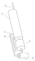
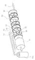
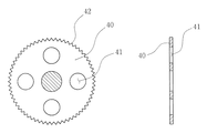
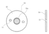
- FIG. 1 is a perspective view showing an oxygen dissolving apparatus according to the present invention. It is a perspective view which shows the mode of the inside of the oxygen dissolving apparatus shown by FIG. It is a figure which shows the mode of the 1st crushing blade by this invention. It is a figure which shows the mode of the 2nd crushing blade by this invention.
- FIG. 1 is a perspective view showing an oxygen dissolving apparatus according to the present invention
- FIG. 2 is a perspective view showing an internal state of the oxygen dissolving apparatus shown in FIG.
- FIG. 3 is a diagram showing a state of the first crushing blade according to the present invention
- FIG. 4 is a diagram showing a state of the second crushing blade according to the present invention.
- the oxygen dissolving apparatus is separated from the electric motor 10, the shaft 20 connected to the motor shaft of the electric motor 10, the impeller 30 provided on the shaft 20, and the shaft 20 by a certain distance.
- a plurality of first crushing blades 40 provided, a plurality of second crushing blades 50 provided between the first crushing blades 40 and the impeller 30, the first crushing blades 40, and the first crushing blades 40.
- a housing 60 surrounding the crushing blade 50.
- the motor shaft of the electric motor 10 rotates in one direction when power is supplied from the outside.
- the shaft 20 is connected in a straight line with the motor shaft of the electric motor 10, and rotates together at the same direction and speed when the motor shaft rotates.
- the impeller 30 is provided at a front portion of the shaft 20, that is, near a motor shaft of the electric motor 10, and rotates together in the same direction and speed when the shaft 20 rotates. Such an impeller 30 generates pressure in the housing 60 while rotating at a high speed according to the shaft 20.
- the first crushing blade 40 is provided so that a central portion thereof penetrates the shaft 20, and is provided on the rear side of the shaft 20 with respect to the impeller 30. More specifically, the first crushing blade 40 has a central portion that is penetrated, the central portion that is penetrated is fixed to the outer surface of the shaft 20, and rotates together at the same direction and speed when the shaft 20 rotates. To do.
- a number of flow holes 41 are formed in the first crushing blade 40 as described above.
- the circulation hole 41 functions as a passage through which water, oxygen, or oxygen-dissolved water in which water and oxygen are mixed passes. Therefore, oxygen that has flowed in through an air inlet 61, which will be described later, and water that has flowed in through a water inlet 62, which will be described later, pass through, and oxygen-dissolved water formed by mixing the oxygen and water will pass through. To do.
- the second crushing blades 50 are provided so that the central portion thereof penetrates the shaft 20, and are provided one by one between the first crushing blades 40. More specifically, the second crushing blade 50 has a central portion that is penetrated, and a bearing 50a is provided in the penetrated central portion so that the rotational force of the shaft 20 is not transmitted. That is, the central portion of the first crushing blade 40 is fixed to the outer surface of the shaft 20 and is restrained by the rotation of the shaft 20, but the bearing 50a of the second crushing blade 50 absorbs the rotational force of the shaft 20, and the shaft 20 , The second crushing blade 50 does not rotate or rotates at a speed different from the rotational speed of the shaft 20.
- a number of flow holes 51 are formed in the second crushing blade 50. Similar to the flow hole 41 formed in the first crushing blade 40, the flow hole 51 serves as a passage through which water, oxygen, or oxygen-dissolved water in which water and oxygen are mixed passes.
- the area of the flow hole 41 formed in the first crushing blade 40 is different from the area of the flow hole 51 formed in the second crushing blade 50. More specifically, the first crushing blade 40 is formed with four flow holes 41 at an angle of 90 degrees, and the second crushing blade 50 is formed with two flow holes 51 at an angle of 180 degrees. The total value of the areas of the four flow holes 41 formed in the first crushing blade 40 is formed larger than the total value of the areas of the two flow holes 51 formed in the second crushing blade 50. Further, even when the flow holes 41 and 51 are made to correspond one by one, the area of one flow hole 41 of the first crushing blade 40 is formed larger than the area of one flow hole 51 of the second crushing blade 50. Is done.
- the reason why the flow holes 41 of the first crushing blade 40 and the flow holes 51 of the second crushing blade 50 are formed to have different areas is as follows. And the velocity of the water passing through the flow hole 51 of the second crushing blade 50 are made to form vortex and turbulent flow, and the vortex and turbulent flow make oxygen better in water and dissolve more. It is.
- the flow hole 51 formed in the second crushing blade 50 is formed so as to be inclined at a certain angle with respect to the shaft 20, and is rotated in one direction by water hitting the surface.
- the bearing 50a is provided at the center of the second crushing blade 50 so that the rotational force of the shaft 20 is not transmitted. In such a state, the flow hole 51 is inclined at a certain angle. If it is formed, it will rotate in a specific direction by the pressure of water.
- the flow hole 51 is formed in the second crushing blade 50, it is formed so as to be inclined in a specific direction such as an upward inclination, a downward inclination, a leftward inclination, or a rightward inclination. If it rotates in the clockwise direction, the second crushing blade 50 is rotated in the counterclockwise direction.
- the first crushing blade 40 Since the first crushing blade 40 is fixed to the shaft 20, if the shaft 20 rotates in the clockwise direction, the second crushing blade 40 rotates in the clockwise direction at the same speed as described above. If the blade 50 is rotated in the counterclockwise direction and the second crushing blade 50 is rotated at a speed different from the rotation speed of the first crushing blade 40 by the bearing 50a, vortex and turbulence are further promoted. , More oxygen becomes soluble in the water.
- irregularities 42 and 52 are repeatedly formed on at least one outer peripheral surface of the first crushing blade 40 and the second crushing blade 50.
- the irregularities 42 and 52 disturb the water flow and promote turbulence.
- a stirring protrusion (not shown) is formed on at least one surface of the first crushing blade 40 and the second crushing blade 50, vortex and turbulence are further promoted. By doing so, oxygen can be further dissolved in water.
- the housing 60 is a long cylinder that surrounds many parts of the present invention except for the electric motor 10 and has a cavity formed therein, and the shaft 20, the impeller 30, the first crushing blade 40, and the first crushing blade 40 in the interior space. 2
- the crushing blade 50 rotates.
- Such a housing 60 is provided with an air inlet 61 and a water inlet 62 and a water outlet 63 on the rear side.
- the air inlet 61 is connected to a high-pressure oxygen cylinder 61 a by a pipe, and oxygen inside the high-pressure oxygen cylinder 61 a is supplied into the housing 60 through the air inlet 61.
- the water inlet 62 is provided to supply external water to the inside of the housing 60, and water supplied through the assistant inlet 62 and oxygen injected through the air inlet 61 are provided. Is agitated inside the housing 60 to become oxygen-dissolved water.
- the water discharge port 63 is a portion from which oxygen dissolved water formed by mixing the oxygen supplied from the air injection port 61 and the water supplied from the water injection port 62 is discharged. That is, oxygen supplied from the air inlet 61 and water supplied from the water inlet 62 are mixed with each other while passing through the first crushing blade 40 and the second crushing blade 50 so as to be dissolved in oxygen. The oxygen-dissolved water is discharged to the outside through the water discharge port 63.
Landscapes
- Chemical & Material Sciences (AREA)
- Life Sciences & Earth Sciences (AREA)
- Chemical Kinetics & Catalysis (AREA)
- Environmental Sciences (AREA)
- Marine Sciences & Fisheries (AREA)
- Animal Husbandry (AREA)
- Biodiversity & Conservation Biology (AREA)
- Dispersion Chemistry (AREA)
- Zoology (AREA)
- Farming Of Fish And Shellfish (AREA)
Abstract
Description
20:シャフト
30:インペラ
40:第1破砕翼
41:流通孔
42:凹凸
50:第2破砕翼
50a:ベアリング
51:流通孔
52:凹凸
60:ハウジング
61:エアー注入口
61a:高圧酸素筒
62:水注入口
63:水排出口
Claims (4)
- 電動モーター10と、前記電動モーター10のモーター軸に連結されて共に回転するシャフト20と、前記シャフト20に設けられてシャフト20が回転する際に共に回転するインペラ30と、前記シャフト20に中央部分が貫通されるように設けられると共にシャフト20に一定の距離だけ離隔するように設けられ、多数の流通孔41が形成された複数の第1破砕翼40と、前記シャフト20に中央部分が貫通されるように設けられると共に、前記第1破砕翼40の間に設けられ、多数の流通孔51が形成された複数の第2破砕翼50と、前記インペラ30と第1破砕翼40及び第2破砕翼50を囲んで酸素が供給されるエア注入口61と水が供給される水注入口62が備えられ、酸素と水が混合された酸素溶解水が排出される水排出口63が備えられたハウジング60と、で構成され、前記第1破砕翼40は、中央部分が前記シャフト20の外側面に固定され、シャフト20が回転する際に共に回転し、前記第2破砕翼50は、貫通された中央部分にベアリング50aが設けられ、前記シャフト20の回転力が伝われないことを特徴とする酸素溶解装置。
- 前記第1破砕翼40に形成された流通孔41の面積と、前記第2破砕翼50に形成された流通孔51の面積と、が異なるように形成されたことを特徴とする、請求項1に記載の酸素溶解装置。
- 前記第2破砕翼50に形成された流通孔51は、シャフト20に対して一定の角度で傾くように形成され、表面にぶつかる水によって一方向に回転されることを特徴とする、請求項1に記載の酸素溶解装置。
- 前記第1破砕翼40と第2破砕翼50とのうち、少なくとも何れか一つの外周面には凹凸42、52が繰り返して形成されることを特徴とする、請求項1に記載の酸素溶解装置。
Priority Applications (4)
| Application Number | Priority Date | Filing Date | Title |
|---|---|---|---|
| CN201580018503.4A CN106455528A (zh) | 2014-04-09 | 2015-03-20 | 氧气溶解装置 |
| US15/302,937 US20170027138A1 (en) | 2014-04-09 | 2015-03-20 | Oxygen dissolution device |
| EP15777441.5A EP3130227A4 (en) | 2014-04-09 | 2015-03-20 | Oxygen dissolution device |
| JP2016512864A JP6480916B2 (ja) | 2014-04-09 | 2015-03-20 | 酸素溶解装置 |
Applications Claiming Priority (2)
| Application Number | Priority Date | Filing Date | Title |
|---|---|---|---|
| KR10-2014-0042320 | 2014-04-09 | ||
| KR20140042320A KR101481940B1 (ko) | 2014-04-09 | 2014-04-09 | 산소용해장치 |
Publications (1)
| Publication Number | Publication Date |
|---|---|
| WO2015156514A1 true WO2015156514A1 (ja) | 2015-10-15 |
Family
ID=52588858
Family Applications (1)
| Application Number | Title | Priority Date | Filing Date |
|---|---|---|---|
| PCT/KR2015/002709 Ceased WO2015156514A1 (ja) | 2014-04-09 | 2015-03-20 | 酸素溶解装置 |
Country Status (6)
| Country | Link |
|---|---|
| US (1) | US20170027138A1 (ja) |
| EP (1) | EP3130227A4 (ja) |
| JP (1) | JP6480916B2 (ja) |
| KR (1) | KR101481940B1 (ja) |
| CN (1) | CN106455528A (ja) |
| WO (1) | WO2015156514A1 (ja) |
Families Citing this family (9)
| Publication number | Priority date | Publication date | Assignee | Title |
|---|---|---|---|---|
| KR101811843B1 (ko) * | 2016-01-25 | 2017-12-26 | 충북대학교 산학협력단 | 이종 유체의 혼합장치 |
| CN107821299B (zh) * | 2016-02-14 | 2020-10-13 | 苏州睿澎诚科技有限公司 | 一种用于现代农业标准化养殖的智能节能加氧设备 |
| CN107980703B (zh) * | 2017-11-30 | 2020-12-01 | 徐州中知知识产权服务有限公司 | 一种水产养殖增氧抑菌喷头装置 |
| CN108328754A (zh) * | 2018-02-01 | 2018-07-27 | 苏州碳酸泉贸易有限公司 | 一种超小型纳米微气泡产生装置 |
| CN108782412B (zh) * | 2018-05-24 | 2021-01-22 | 华南农业大学 | 一种自动电解式增氧器及增氧方法 |
| KR102091979B1 (ko) * | 2019-10-11 | 2020-03-20 | 유영호 | 마찰력을 이용한 나노 버블 생성시스템 |
| KR102380273B1 (ko) | 2020-01-15 | 2022-03-29 | 주식회사 네오엔비즈 | 양식장 사육수 산소공급을 위한 산소용해장치 |
| KR102260745B1 (ko) * | 2020-02-04 | 2021-06-07 | 유영호 | 마찰을 이용한 나노 버블 생성 시스템 |
| CN113575501B (zh) * | 2021-08-27 | 2023-09-29 | 湖南农业大学 | 一种推水增氧装置及其养殖槽 |
Citations (2)
| Publication number | Priority date | Publication date | Assignee | Title |
|---|---|---|---|---|
| JP2009039600A (ja) * | 2007-08-06 | 2009-02-26 | Reo Laboratory Co Ltd | 超微細気泡生成装置 |
| JP2010240562A (ja) * | 2009-04-03 | 2010-10-28 | Mitsuhisa Matsuoka | 微細気泡分散水の製造装置 |
Family Cites Families (11)
| Publication number | Priority date | Publication date | Assignee | Title |
|---|---|---|---|---|
| US2092992A (en) * | 1935-08-19 | 1937-09-14 | Daniel E Thalman | Emulsifying apparatus |
| US3822999A (en) * | 1972-03-30 | 1974-07-09 | Univ Brigham Young | Liquid-liquid extraction and plug-flow reactor apparatus |
| US4370062A (en) * | 1980-02-19 | 1983-01-25 | Moody Warren E | Dispensing gun for two-part adhesives |
| US4874248A (en) * | 1988-07-27 | 1989-10-17 | Marathon Oil Company | Apparatus and method for mixing a gel and liquid |
| US5868495A (en) * | 1991-07-08 | 1999-02-09 | Hidalgo; Oscar Mario Guagnelli | Method for treating fluent materials |
| JPH07327547A (ja) * | 1994-06-07 | 1995-12-19 | Toshiyuki Takatsu | 酸素混合水の供給方法及び装置 |
| US6337308B1 (en) * | 1999-06-08 | 2002-01-08 | Diamond Tank Rentals, Inc. | Method and apparatus for homogenizing drilling fluid in an open-loop process |
| KR100631323B1 (ko) | 2004-12-31 | 2006-10-12 | 최호상 | 저수지 정화장치 |
| EP1754530A1 (de) * | 2005-08-18 | 2007-02-21 | StaMixCo Technology AG | Mischelement zum Invertieren und Mischen von strömenden Stoffen in einem Strömungskanal, Bausatz und Mischer enthaltend dergestalte Mischelemente, sowie Verfahren zum Mischen eines strömenden Stoffes in einem Strömungskanal |
| KR100759200B1 (ko) * | 2007-03-21 | 2007-09-14 | 박현린 | 산소용해장치 |
| KR100938940B1 (ko) * | 2009-06-15 | 2010-01-27 | (주)상진엔지니어링 | 산소용해장치 |
-
2014
- 2014-04-09 KR KR20140042320A patent/KR101481940B1/ko not_active Expired - Fee Related
-
2015
- 2015-03-20 US US15/302,937 patent/US20170027138A1/en not_active Abandoned
- 2015-03-20 JP JP2016512864A patent/JP6480916B2/ja not_active Expired - Fee Related
- 2015-03-20 CN CN201580018503.4A patent/CN106455528A/zh active Pending
- 2015-03-20 WO PCT/KR2015/002709 patent/WO2015156514A1/ja not_active Ceased
- 2015-03-20 EP EP15777441.5A patent/EP3130227A4/en not_active Withdrawn
Patent Citations (2)
| Publication number | Priority date | Publication date | Assignee | Title |
|---|---|---|---|---|
| JP2009039600A (ja) * | 2007-08-06 | 2009-02-26 | Reo Laboratory Co Ltd | 超微細気泡生成装置 |
| JP2010240562A (ja) * | 2009-04-03 | 2010-10-28 | Mitsuhisa Matsuoka | 微細気泡分散水の製造装置 |
Non-Patent Citations (1)
| Title |
|---|
| See also references of EP3130227A4 * |
Also Published As
| Publication number | Publication date |
|---|---|
| CN106455528A (zh) | 2017-02-22 |
| JP6480916B2 (ja) | 2019-03-13 |
| EP3130227A1 (en) | 2017-02-15 |
| KR101481940B1 (ko) | 2015-01-13 |
| JPWO2015156514A1 (ja) | 2017-04-13 |
| US20170027138A1 (en) | 2017-02-02 |
| EP3130227A4 (en) | 2017-08-02 |
Similar Documents
| Publication | Publication Date | Title |
|---|---|---|
| JP6480916B2 (ja) | 酸素溶解装置 | |
| JP2011005349A (ja) | 攪拌用回転体および攪拌装置 | |
| CN202490592U (zh) | 粉液体混合装置 | |
| CN108064216A (zh) | 曝气机 | |
| WO2008007631A1 (en) | Fine bubble generating unit | |
| CN201411391Y (zh) | 具有双层叶轮的曝气搅拌装置 | |
| JP4377087B2 (ja) | 気液混合溶解装置 | |
| KR101632020B1 (ko) | 기포 용해 장치 | |
| JP2012125690A (ja) | 貫流ポンプエアレ−ション装置 | |
| KR101254873B1 (ko) | 폭기장치 | |
| CN104722230B (zh) | 一种搅拌装置 | |
| US10532331B2 (en) | Artificial-whirlpool generator | |
| CN204110659U (zh) | 粉体落料装置 | |
| CN203058114U (zh) | 一种气液混合发生装置 | |
| JP2002166151A (ja) | 微細気泡供給方法および微細気泡供給装置 | |
| KR101231318B1 (ko) | 용액혼합장치 | |
| JP2009045598A (ja) | 流体攪拌装置 | |
| WO2015137411A1 (ja) | 攪拌装置 | |
| CN205598983U (zh) | 一种水体导入气体的气水混合装置 | |
| CN103931547A (zh) | 新型高压气泡粉碎装置 | |
| CN209715416U (zh) | 一种新型浮选机预混进料装置 | |
| JP2018069159A (ja) | ディスク回転型微細気泡発生方法及び装置 | |
| CN212237058U (zh) | 一种水性表面处理剂研磨分散装置 | |
| JPH03229696A (ja) | 気泡発生装置 | |
| CN111389250A (zh) | 一种局部对流装置及其工业液体物料混合设备 |
Legal Events
| Date | Code | Title | Description |
|---|---|---|---|
| 121 | Ep: the epo has been informed by wipo that ep was designated in this application |
Ref document number: 15777441 Country of ref document: EP Kind code of ref document: A1 |
|
| ENP | Entry into the national phase |
Ref document number: 2016512864 Country of ref document: JP Kind code of ref document: A |
|
| WWE | Wipo information: entry into national phase |
Ref document number: 15302937 Country of ref document: US |
|
| NENP | Non-entry into the national phase |
Ref country code: DE |
|
| REEP | Request for entry into the european phase |
Ref document number: 2015777441 Country of ref document: EP |
|
| WWE | Wipo information: entry into national phase |
Ref document number: 2015777441 Country of ref document: EP |