WO2015159634A1 - 偏肉調整型エアーリング - Google Patents
偏肉調整型エアーリング Download PDFInfo
- Publication number
- WO2015159634A1 WO2015159634A1 PCT/JP2015/057986 JP2015057986W WO2015159634A1 WO 2015159634 A1 WO2015159634 A1 WO 2015159634A1 JP 2015057986 W JP2015057986 W JP 2015057986W WO 2015159634 A1 WO2015159634 A1 WO 2015159634A1
- Authority
- WO
- WIPO (PCT)
- Prior art keywords
- cooling air
- synthetic resin
- circumferential direction
- flow path
- thickness
- Prior art date
- Legal status (The legal status is an assumption and is not a legal conclusion. Google has not performed a legal analysis and makes no representation as to the accuracy of the status listed.)
- Ceased
Links
Images



Classifications
-
- B—PERFORMING OPERATIONS; TRANSPORTING
- B29—WORKING OF PLASTICS; WORKING OF SUBSTANCES IN A PLASTIC STATE IN GENERAL
- B29C—SHAPING OR JOINING OF PLASTICS; SHAPING OF MATERIAL IN A PLASTIC STATE, NOT OTHERWISE PROVIDED FOR; AFTER-TREATMENT OF THE SHAPED PRODUCTS, e.g. REPAIRING
- B29C48/00—Extrusion moulding, i.e. expressing the moulding material through a die or nozzle which imparts the desired form; Apparatus therefor
- B29C48/25—Component parts, details or accessories; Auxiliary operations
- B29C48/88—Thermal treatment of the stream of extruded material, e.g. cooling
- B29C48/885—External treatment, e.g. by using air rings for cooling tubular films
-
- B—PERFORMING OPERATIONS; TRANSPORTING
- B29—WORKING OF PLASTICS; WORKING OF SUBSTANCES IN A PLASTIC STATE IN GENERAL
- B29C—SHAPING OR JOINING OF PLASTICS; SHAPING OF MATERIAL IN A PLASTIC STATE, NOT OTHERWISE PROVIDED FOR; AFTER-TREATMENT OF THE SHAPED PRODUCTS, e.g. REPAIRING
- B29C48/00—Extrusion moulding, i.e. expressing the moulding material through a die or nozzle which imparts the desired form; Apparatus therefor
- B29C48/03—Extrusion moulding, i.e. expressing the moulding material through a die or nozzle which imparts the desired form; Apparatus therefor characterised by the shape of the extruded material at extrusion
- B29C48/09—Articles with cross-sections having partially or fully enclosed cavities, e.g. pipes or channels
- B29C48/10—Articles with cross-sections having partially or fully enclosed cavities, e.g. pipes or channels flexible, e.g. blown foils
-
- B—PERFORMING OPERATIONS; TRANSPORTING
- B29—WORKING OF PLASTICS; WORKING OF SUBSTANCES IN A PLASTIC STATE IN GENERAL
- B29C—SHAPING OR JOINING OF PLASTICS; SHAPING OF MATERIAL IN A PLASTIC STATE, NOT OTHERWISE PROVIDED FOR; AFTER-TREATMENT OF THE SHAPED PRODUCTS, e.g. REPAIRING
- B29C48/00—Extrusion moulding, i.e. expressing the moulding material through a die or nozzle which imparts the desired form; Apparatus therefor
- B29C48/25—Component parts, details or accessories; Auxiliary operations
- B29C48/30—Extrusion nozzles or dies
- B29C48/32—Extrusion nozzles or dies with annular openings, e.g. for forming tubular articles
-
- B—PERFORMING OPERATIONS; TRANSPORTING
- B29—WORKING OF PLASTICS; WORKING OF SUBSTANCES IN A PLASTIC STATE IN GENERAL
- B29C—SHAPING OR JOINING OF PLASTICS; SHAPING OF MATERIAL IN A PLASTIC STATE, NOT OTHERWISE PROVIDED FOR; AFTER-TREATMENT OF THE SHAPED PRODUCTS, e.g. REPAIRING
- B29C48/00—Extrusion moulding, i.e. expressing the moulding material through a die or nozzle which imparts the desired form; Apparatus therefor
- B29C48/25—Component parts, details or accessories; Auxiliary operations
- B29C48/88—Thermal treatment of the stream of extruded material, e.g. cooling
- B29C48/911—Cooling
- B29C48/9115—Cooling of hollow articles
- B29C48/912—Cooling of hollow articles of tubular films
-
- B—PERFORMING OPERATIONS; TRANSPORTING
- B29—WORKING OF PLASTICS; WORKING OF SUBSTANCES IN A PLASTIC STATE IN GENERAL
- B29C—SHAPING OR JOINING OF PLASTICS; SHAPING OF MATERIAL IN A PLASTIC STATE, NOT OTHERWISE PROVIDED FOR; AFTER-TREATMENT OF THE SHAPED PRODUCTS, e.g. REPAIRING
- B29C48/00—Extrusion moulding, i.e. expressing the moulding material through a die or nozzle which imparts the desired form; Apparatus therefor
- B29C48/25—Component parts, details or accessories; Auxiliary operations
- B29C48/92—Measuring, controlling or regulating
-
- B—PERFORMING OPERATIONS; TRANSPORTING
- B29—WORKING OF PLASTICS; WORKING OF SUBSTANCES IN A PLASTIC STATE IN GENERAL
- B29C—SHAPING OR JOINING OF PLASTICS; SHAPING OF MATERIAL IN A PLASTIC STATE, NOT OTHERWISE PROVIDED FOR; AFTER-TREATMENT OF THE SHAPED PRODUCTS, e.g. REPAIRING
- B29C55/00—Shaping by stretching, e.g. drawing through a die; Apparatus therefor
- B29C55/28—Shaping by stretching, e.g. drawing through a die; Apparatus therefor of blown tubular films, e.g. by inflation
-
- B—PERFORMING OPERATIONS; TRANSPORTING
- B29—WORKING OF PLASTICS; WORKING OF SUBSTANCES IN A PLASTIC STATE IN GENERAL
- B29C—SHAPING OR JOINING OF PLASTICS; SHAPING OF MATERIAL IN A PLASTIC STATE, NOT OTHERWISE PROVIDED FOR; AFTER-TREATMENT OF THE SHAPED PRODUCTS, e.g. REPAIRING
- B29C2948/00—Indexing scheme relating to extrusion moulding
- B29C2948/92—Measuring, controlling or regulating
- B29C2948/92009—Measured parameter
- B29C2948/92114—Dimensions
- B29C2948/92152—Thickness
-
- B—PERFORMING OPERATIONS; TRANSPORTING
- B29—WORKING OF PLASTICS; WORKING OF SUBSTANCES IN A PLASTIC STATE IN GENERAL
- B29C—SHAPING OR JOINING OF PLASTICS; SHAPING OF MATERIAL IN A PLASTIC STATE, NOT OTHERWISE PROVIDED FOR; AFTER-TREATMENT OF THE SHAPED PRODUCTS, e.g. REPAIRING
- B29C2948/00—Indexing scheme relating to extrusion moulding
- B29C2948/92—Measuring, controlling or regulating
- B29C2948/92323—Location or phase of measurement
- B29C2948/92447—Moulded article
-
- B—PERFORMING OPERATIONS; TRANSPORTING
- B29—WORKING OF PLASTICS; WORKING OF SUBSTANCES IN A PLASTIC STATE IN GENERAL
- B29C—SHAPING OR JOINING OF PLASTICS; SHAPING OF MATERIAL IN A PLASTIC STATE, NOT OTHERWISE PROVIDED FOR; AFTER-TREATMENT OF THE SHAPED PRODUCTS, e.g. REPAIRING
- B29C2948/00—Indexing scheme relating to extrusion moulding
- B29C2948/92—Measuring, controlling or regulating
- B29C2948/92504—Controlled parameter
- B29C2948/9258—Velocity
- B29C2948/926—Flow or feed rate
-
- B—PERFORMING OPERATIONS; TRANSPORTING
- B29—WORKING OF PLASTICS; WORKING OF SUBSTANCES IN A PLASTIC STATE IN GENERAL
- B29C—SHAPING OR JOINING OF PLASTICS; SHAPING OF MATERIAL IN A PLASTIC STATE, NOT OTHERWISE PROVIDED FOR; AFTER-TREATMENT OF THE SHAPED PRODUCTS, e.g. REPAIRING
- B29C2948/00—Indexing scheme relating to extrusion moulding
- B29C2948/92—Measuring, controlling or regulating
- B29C2948/92504—Controlled parameter
- B29C2948/92609—Dimensions
- B29C2948/92657—Volume or quantity
-
- B—PERFORMING OPERATIONS; TRANSPORTING
- B29—WORKING OF PLASTICS; WORKING OF SUBSTANCES IN A PLASTIC STATE IN GENERAL
- B29C—SHAPING OR JOINING OF PLASTICS; SHAPING OF MATERIAL IN A PLASTIC STATE, NOT OTHERWISE PROVIDED FOR; AFTER-TREATMENT OF THE SHAPED PRODUCTS, e.g. REPAIRING
- B29C2948/00—Indexing scheme relating to extrusion moulding
- B29C2948/92—Measuring, controlling or regulating
- B29C2948/92819—Location or phase of control
- B29C2948/92971—Fluids, e.g. for temperature control or of environment
-
- B—PERFORMING OPERATIONS; TRANSPORTING
- B29—WORKING OF PLASTICS; WORKING OF SUBSTANCES IN A PLASTIC STATE IN GENERAL
- B29K—INDEXING SCHEME ASSOCIATED WITH SUBCLASSES B29B, B29C OR B29D, RELATING TO MOULDING MATERIALS OR TO MATERIALS FOR MOULDS, REINFORCEMENTS, FILLERS OR PREFORMED PARTS, e.g. INSERTS
- B29K2105/00—Condition, form or state of moulded material or of the material to be shaped
- B29K2105/0058—Liquid or visquous
- B29K2105/0067—Melt
-
- B—PERFORMING OPERATIONS; TRANSPORTING
- B29—WORKING OF PLASTICS; WORKING OF SUBSTANCES IN A PLASTIC STATE IN GENERAL
- B29L—INDEXING SCHEME ASSOCIATED WITH SUBCLASS B29C, RELATING TO PARTICULAR ARTICLES
- B29L2023/00—Tubular articles
- B29L2023/001—Tubular films, sleeves
Definitions
- the present invention is placed on the die of an inflation film manufacturing apparatus for molding a synthetic resin film, and when cooling plastic is blown around the extruded synthetic resin tube to cool and solidify it to form a synthetic resin film,
- the present invention relates to a thickness adjustment type air ring that adjusts the thickness deviation (thickness variation) of a synthetic resin film by partially controlling the amount of cooling air in the circumferential direction.
- a melted synthetic resin tube extruded from a die slit is generally cooled and solidified to form a synthetic resin film (see, for example, Patent Document 1).
- the inflation film manufacturing apparatus of Patent Document 1 includes a die head having a ring nozzle and an outer blowing nozzle, and a measurement device for measuring the film thickness of the tubular film, and an air nozzle group according to the measurement result of the measurement device The air flow rate through the nozzles is controlled.
- Non-Patent Document 1 an inflation film manufacturing apparatus that controls the uneven thickness of the synthetic resin film by partially providing a difference in the air volume in the circumferential direction with respect to the cooling air has been proposed (see, for example, Non-Patent Document 1).
- an air ring in this type of blown film manufacturing apparatus for example, those shown in FIGS. 9 to 11 are known.
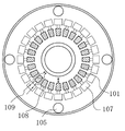
- FIG. 9 a large number of block-shaped inclined members 101 are annularly arranged in the cooling air flow path in the air ring 100, and the inclined members 101 are moved in the radial direction by a moving portion 107 such as a motor.
- the amount of cooling air directed toward the molten synthetic resin tube 104 can be partially controlled in the circumferential direction. It has become. 9 and 10 is a hose port, and cooling air 106 from a blower (not shown) is introduced through a hose (not shown) connected to the hose port 105. In the illustrated example, four hose openings 105 are formed at predetermined intervals in the circumferential direction.
- the air ring 100 having the configuration of the example described above, it is necessary to form a gap 108 between the adjacent inclined members 101 in order to move the inclined member 101 in the radial direction. If there is no gap 108, the inclined members 101 interfere with each other and cannot move radially inward from the position. Further, even if the gap 108 between the inclined members 101 is set so as not to exist radially inside, the gap 108 can be moved radially outward from the position, but after all, the gap 108 is moved when moved radially outward. Occurs.
- the flow of the cooling air is disturbed as indicated by the streamline 109 in FIG. Further, the cooling air flowing through the portion other than the gap 108 is controlled by each inclined member 101, but the cooling air flowing through the gap 108 flows regardless of the gap of the flow path 103 formed by each inclined member 101.
- the cooling air flowing through is not controllable. Since the uneven thickness of the synthetic resin film depends on the flow state such as the air volume of the cooling air, there is a problem that a portion where the uneven thickness cannot be controlled occurs in the synthetic resin film.
- the present invention has been made in view of the above problems, and can accurately and optimally control the cooling air volume at all locations in the circumferential direction, and stably produce a synthetic resin film excellent in uneven thickness.
- An object of the present invention is to provide a thickness adjustment type air ring that can be adjusted.
- a synthetic resin film is formed by blowing cooling air around a molten synthetic resin tube which is installed on a die of an inflation film manufacturing apparatus and is extruded in the longitudinal direction to cool and solidify.
- the uneven thickness adjustment type air ring that adjusts the uneven thickness of the synthetic resin film by partially controlling the air volume of the cooling air discharged from the cooling air channel in the circumferential direction, the circumferential direction in the cooling air channel Are connected to a predetermined position in the circumferential direction of the flow path adjusting unit, and the connection part of the flow path adjusting unit is moved in a predetermined direction independently of other parts.
- a plurality of moving parts and partially adjusting a space in which the cooling air can flow in the cooling air flow path in the circumferential direction, and partially controlling the air volume of the cooling air in the circumferential direction.
- Uneven thickness regulated air ring which is adapted is provided.
- the flow path adjusting portion may be formed of an annular elastic member formed continuously in the circumferential direction.
- the moving part may move the connecting portion of the elastic member in the longitudinal direction of the molten synthetic resin tube.
- the moving part may move a connecting portion of the elastic member in a radial direction of the molten synthetic resin tube.
- the flow path adjusting portion may be composed of a plurality of movable members arranged in a ring shape without any gap in the circumferential direction and movable in the longitudinal direction of the molten synthetic resin tube.
- the moving unit may move the movable member in the longitudinal direction of the molten synthetic resin tube.
- the amount of cooling air can be accurately and optimally controlled at all locations in the circumferential direction, and a synthetic resin film excellent in uneven thickness can be stably produced.
- FIG. 1 is a schematic configuration diagram of an inflation film manufacturing apparatus showing a first embodiment of the present invention.
- FIG. 2 is a schematic cross-sectional view of an inflation film manufacturing apparatus around a thickness adjustment type air ring.
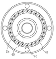
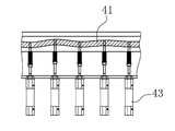
- 3 is a cross-sectional view taken along the line AA in FIG. 4 is a cross-sectional view taken along the line BB of FIG.
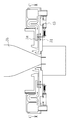
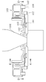
- FIG. 5 is a schematic cross-sectional view of an inflation film manufacturing apparatus around a thickness adjustment type air ring showing a second embodiment of the present invention.
- 6 is a cross-sectional view taken along the line CC of FIG.
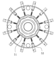
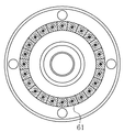
- FIG. 7 is a plan cross-sectional view of a thickness adjustment type air ring showing a third embodiment of the present invention.
- FIG. 1 is a schematic configuration diagram of an inflation film manufacturing apparatus showing a first embodiment of the present invention.
- FIG. 2 is a schematic cross-sectional view of an inflation film manufacturing apparatus around a thickness adjustment type air ring.
- 3 is a cross-sectional view taken
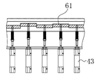
- FIG. 8 is a side cross-sectional view of the uneven thickness adjustment type air ring.
- FIG. 9 is a plan sectional view of a conventional uneven thickness adjusting type air ring.
- 10 is a cross-sectional view taken along the line DD of FIG. 11 is a cross-sectional view taken along line EE in FIG.
- FIG. 1 is a schematic configuration diagram of an inflation film manufacturing apparatus
- FIG. 2 is a schematic cross-sectional view of an inflation film manufacturing apparatus around a thickness adjustment type air ring
- FIG. 3 is a cross-sectional view taken along line AA in FIG. 2
- FIG. 4 is a cross-sectional view taken along line BB in FIG.
- a molten synthetic resin 3 a supplied from an extruder (not shown) to a die 2 is extruded from a die slit 2 a as a molten synthetic resin tube 3.
- the extruded molten synthetic resin tube 3 is thinly stretched in both the longitudinal direction and the radial direction, and at the same time is cooled with cooling air 5 from a blower (not shown) to form a tubular synthetic resin film 3b.
- the synthetic resin film 3b is taken up by the pinch roll 6 and taken up by a winder (not shown). Note that air of a predetermined pressure is sealed inside the molten synthetic resin tube 3 (tube-shaped synthetic resin film 3b).
- a thickness adjustment type air ring 4 for adjusting the thickness deviation of the synthetic resin film 3b by partially controlling the air volume of the cooling air 5 discharged from the cooling air flow path 48 (see FIG. 2) in the circumferential direction.
- a thickness sensor 7 for measuring the thickness of the tube-shaped synthetic resin film 3b is provided in the upstream portion of the pinch roll 6.
- the thickness sensor 7 is, for example, a capacitance type, a laser type, or the like, and a detection signal related to the thickness deviation information of the synthetic resin film 3b is input from the thickness sensor 7 to a control unit 8 including a computer or the like.
- the control unit 8 is an annular flow path continuously arranged in the circumferential direction in the cooling air flow path 48 of the air ring 4 based on the thickness deviation information of the synthetic resin film 3b obtained from the detection signal from the thickness sensor 7. By adjusting the adjustment portion with the moving portion, the air volume is partially controlled in the circumferential direction with respect to the cooling air 5 flowing in the cooling air passage 48 so that the uneven thickness of the synthetic resin film 3b is made small and uniform. .
- the air ring 4 is arranged in a horizontal shape and has a ring shape in which a radially inner side of the upper surface is recessed.
- the air ring 4 has an annular blowing port 45 formed in the inner peripheral portion thereof, and is fixed on the die 2 by an appropriate means so as to be concentric with the ring-shaped die slit 2a in the die 2. .
- a cooling air reservoir 44 is defined by an annular rectifying plate 46 on the radially outer side inside the air ring 4.
- four hose openings 40 are formed at equal intervals in the cooling air reservoir 44 in the circumferential direction, and the cooling air 5 from a blower (not shown) is connected to the hose openings 40 via the hose. Has been introduced.
- a cooling air passage 48 connected to the cooling air reservoir 44 is formed inside the air ring 4 in the radial direction, and an annular elastic member 41 continuously formed in the cooling air passage 48 in the circumferential direction. Is disposed.
- the elastic member 41 forms an annular flow path adjusting portion that is continuously arranged in the cooling air flow path 48 in the circumferential direction.
- the elastic member 41 is connected to rod portions of a plurality of air cylinders 43 arranged in the circumferential direction.
- each air cylinder 43 is connected to a predetermined position in the circumferential direction of the flow path adjustment unit, and has a moving unit that moves the connection part of the flow path adjustment unit in a predetermined direction independently of the other parts. ing.
- a coil spring 42 is attached to the rod portion of the air cylinder 43 so as to oppose the movement of the rod.
- the cooling air 5 from a blower (not shown) is branched into four hoses and introduced into the outer cooling air reservoir 44 of the air ring 4 through the hose port 40.
- the cooling air 5 is rectified into a uniform flow toward the center in the radial direction while being snaked up and down by the rectifying plates 46 and 47, and blown to the molten synthetic resin tube 3 from the blowing port 45.
- the cooling air passage 48 extends in the radial direction of the molten synthetic resin tube 3, and each air cylinder 43 connects the connecting portion of the elastic member 41 in the longitudinal direction of the molten synthetic resin tube 3, that is, the extending direction of the cooling air passage 48.
- the width dimension of the cooling air flow path 48 is, for example, 3 mm to 50 mm.
- the elastic member 41 of the endless structure has no gap such as a joint, the elastic member 41 does not disturb the cooling air 5 rectified by the rectifying plates 46, 47 and the like. Further, the space in which the cooling air 5 can flow in the cooling air flow channel 48 is partially adjusted by the elastic member 41 in the circumferential direction, and the air volume of the cooling air 5 can be reliably controlled in all parts in the circumferential direction. .
- the solidified portion of the melted synthetic resin tube 3 pushed out from the die slit 2a is not stretched and is not further thinned, but the unsolidified portion is stretched and thinned until solidified. Therefore, if the air volume of the cooling air 5 corresponding to the thick part in the circumferential direction of the tube-shaped synthetic resin film 3b is lowered, the cooling / solidification of the part of the molten synthetic resin tube 3 is delayed and thinned, so the synthetic resin film 3b.
- the uneven thickness can be controlled.
- the control unit 8 When the air pressure 49 supplied to the air cylinder 43 corresponding to the thick portion of the tube-shaped synthetic resin film 3b is increased by the control unit 8 based on the thickness deviation information of the thickness sensor 7, the position balances with the force of the coil spring 42. Since the air cylinder 43 moves the elastic member 41 in a direction perpendicular to the horizontal plane, the cooling air flow path 48 becomes narrow. As a result, the air volume of the thick portion is reduced, and the corresponding portion of the melted synthetic resin tube 3 is thinned, resulting in a uniform tube-shaped synthetic resin film 3b having a small uneven thickness.
- the elastic member 41 since the elastic member 41 is too hard to be deformed, rubber having a hardness of 70 ° (JIS-A) or less is desirable. Further, the elastic member 41 may be adjusted with a stepping motor or the like instead of the air cylinder 43, or may be manually adjusted instead of a bolt or the like.
- the uneven thickness adjustment type air ring 4 configured as described above, there is no need to provide a gap in the circumferential direction, and the uneven thickness cannot be partially controlled. Therefore, a uniform synthetic resin film 3b with a small uneven thickness can be formed.
- the air ring 4 of the inflation manufacturing apparatus 1 of the first embodiment was produced and tested.
- LLDPE having an MFR of 1 was used as a raw material for the molten synthetic resin 3a
- continuous operation was performed for 5 hours under the manufacturing conditions of a tube diameter of 1000 mm, a thickness of 50 ⁇ m, and a take-off speed of 23 m / min.
- a synthetic resin film 3b having a thickness of 0.4% (thickness variation based on the average thickness) could be formed.
- FIG. 5 and 6 show a second embodiment of the present invention
- FIG. 5 is a schematic sectional view of an inflation film manufacturing apparatus
- FIG. 6 is a sectional view taken along the line CC of FIG.
- the elastic member 41 is moved in the longitudinal direction of the molten synthetic resin tube 3, but the direction in which the flow path adjusting unit is moved can be arbitrarily set.
- the air cylinder 43 moves the connecting portion of the elastic member 51 in the radial direction of the molten synthetic resin tube 3 so that the gap of the cooling air flow path 58 is partially formed. Therefore, the uneven thickness of the synthetic resin film 3b is controlled by partially adjusting the air volume of the cooling air.
- FIG. 7 and 8 show a third embodiment of the present invention.
- FIG. 7 is a plan sectional view of the thickness adjustment type air ring
- FIG. 8 is a side sectional view of the thickness adjustment type air ring.
- the flow path adjusting portions are arranged in a ring shape without any gap in the circumferential direction, and are a plurality of movable members 61 that are movable in the longitudinal direction of the molten synthetic resin tube 3.
- the movable member 61 can be moved in the direction perpendicular to the horizontal plane by the air cylinder 43, and there is no gap between the movable members 61. Therefore, the flow of the cooling air 5 is not disturbed, and there are places where the cooling air 5 is not controlled.
- the cooling air can be partially controlled as intended.
- the uneven thickness adjustment type air ring of the present invention can accurately and optimally control the cooling air volume at all locations in the circumferential direction, and can stably produce a synthetic resin film excellent in uneven thickness. , Industrially useful.
Landscapes
- Engineering & Computer Science (AREA)
- Mechanical Engineering (AREA)
- Physics & Mathematics (AREA)
- Thermal Sciences (AREA)
- Manufacturing & Machinery (AREA)
- Extrusion Moulding Of Plastics Or The Like (AREA)
- Shaping By String And By Release Of Stress In Plastics And The Like (AREA)
Abstract
Description
第1の実施形態においては、弾性部材41を溶融合成樹脂チューブ3の長手方向に移動するようにしているが、流路調整部を移動させる方向は任意に設定することができる。第2の実施形態においては、図5及び図6に示すように、エアーシリンダー43が弾性部材51の接続部分を溶融合成樹脂チューブ3の径方向に移動することで冷却風流路58の隙間を部分的に調節し、冷却風の風量を部分的に調節する事で合成樹脂フィルム3bの偏肉を制御している。
本実施形態においては、流路調整部を周方向に隙間なく環状に並べられ溶融合成樹脂チューブ3の長手方向へ移動可能な複数の可動部材61としている。可動部材61はエアーシリンダー43で水平面に対して垂直方向に動かすことが出来、可動部材61間に隙間が無いので、冷却風5の流れが乱れる事も無く且つ、冷却風5が制御されない箇所もなく冷却風を部分的に目的通りの制御が出来る。
2 ダイ
2a ダイスリット
3 溶融合成樹脂チューブ
3a 溶融合成樹脂
3b 合成樹脂フィルム
4 エアーリング
5 冷却風
7 厚みセンサー
8 制御ユニット
40 ホース口
41 弾性部材
42 コイルスプリング
43 エアリンダー
45 吹き出し口
46 整流板
47 整流板
48 冷却風流路
51 弾性部材
58 冷却風流路
61 可動部材
100 エアーリング
101 傾斜部材
102 吹き出しリング
103 流路
104 溶融合成樹脂チューブ
105 ホース口
106 冷却風
107 移動部
108 間隙
Claims (6)
- インフレーションフィルム製造装置のダイ上に設置され、長手方向に押し出される溶融合成樹脂チューブの周囲へ冷却風を吹き付けて冷却・固化させて合成樹脂フィルムを成形する際に、冷却風流路から吐出される前記冷却風の風量を周方向で部分的に制御して合成樹脂フィルムの偏肉を調整する偏肉調整型エアーリングにおいて、
前記冷却風流路内に周方向に連続的に配置された環状の流路調節部と、
前記流路調節部における周方向の所定位置に接続され、前記流路調節部の接続部分を他の部分と独立して所定方向へ移動させる複数の移動部と、を備え、
前記冷却風流路内における前記冷却風の流通可能な空間を周方向について部分的に調節し、前記冷却風の風量を周方向について部分的に制御するようにした偏肉調整型エアーリング。 - 前記流路調整部は、周方向に連続的に形成された環状の弾性部材からなる請求項1に記載の偏肉調整型エアーリング。
- 前記移動部は、前記弾性部材の接続部分を前記溶融合成樹脂チューブの長手方向へ移動させる請求項2に記載の偏肉調整型エアーリング。
- 前記移動部は、前記弾性部材の接続部分を前記溶融合成樹脂チューブの径方向へ移動させる請求項2に記載の偏肉調整型エアーリング。
- 前記流路調整部は、周方向に隙間なく環状に並べられ前記溶融合成樹脂チューブの長手方向へ移動可能な複数の可動部材からなる請求項1に記載の偏肉調整型エアーリング。
- 前記移動部は、前記可動部材を前記溶融合成樹脂チューブの長手方向へ移動させる請求項5に記載の偏肉調整型エアーリング。
Priority Applications (5)
| Application Number | Priority Date | Filing Date | Title |
|---|---|---|---|
| CN201580018984.9A CN106163766B (zh) | 2014-04-14 | 2015-03-18 | 厚度不均调整型气环 |
| EP15779799.4A EP3132913B1 (en) | 2014-04-14 | 2015-03-18 | Thickness variation-adjusting air ring |
| US15/301,244 US10232543B2 (en) | 2014-04-14 | 2015-03-18 | Thickness variation-adjusting air ring |
| KR1020167027900A KR102270002B1 (ko) | 2014-04-14 | 2015-03-18 | 두께 편차 조정형 에어 링 |
| CA2944135A CA2944135C (en) | 2014-04-14 | 2015-03-18 | Thickness variation adjustment-type air ring |
Applications Claiming Priority (2)
| Application Number | Priority Date | Filing Date | Title |
|---|---|---|---|
| JP2014-083122 | 2014-04-14 | ||
| JP2014083122A JP5634630B1 (ja) | 2014-04-14 | 2014-04-14 | 偏肉調整型エアーリング |
Publications (1)
| Publication Number | Publication Date |
|---|---|
| WO2015159634A1 true WO2015159634A1 (ja) | 2015-10-22 |
Family
ID=52139040
Family Applications (1)
| Application Number | Title | Priority Date | Filing Date |
|---|---|---|---|
| PCT/JP2015/057986 Ceased WO2015159634A1 (ja) | 2014-04-14 | 2015-03-18 | 偏肉調整型エアーリング |
Country Status (8)
| Country | Link |
|---|---|
| US (1) | US10232543B2 (ja) |
| EP (1) | EP3132913B1 (ja) |
| JP (1) | JP5634630B1 (ja) |
| KR (1) | KR102270002B1 (ja) |
| CN (1) | CN106163766B (ja) |
| CA (1) | CA2944135C (ja) |
| TW (1) | TWI532585B (ja) |
| WO (1) | WO2015159634A1 (ja) |
Families Citing this family (19)
| Publication number | Priority date | Publication date | Assignee | Title |
|---|---|---|---|---|
| JP6366527B2 (ja) * | 2015-03-11 | 2018-08-01 | 住友重機械モダン株式会社 | フィルム成形装置のバルブ装置 |
| EP3088370B1 (de) * | 2015-04-28 | 2018-09-26 | Heraeus Quarzglas GmbH & Co. KG | Verfahren und vorrichtung zur herstellung eines rohres aus glas |
| ITUB20151292A1 (it) * | 2015-05-28 | 2016-11-28 | Doteco S P A | Apparato e metodo per produrre un film estruso in bolla |
| WO2017150307A1 (ja) * | 2016-02-29 | 2017-09-08 | 株式会社Tbm | インフレーションフィルムの製造方法及びインフレーション成形装置 |
| JP6704644B2 (ja) * | 2016-03-28 | 2020-06-03 | 住友重機械モダン株式会社 | フィルム成形装置 |
| US11524438B2 (en) * | 2016-08-23 | 2022-12-13 | Windmöller & Hölscher Kg | Apparatus and method for film production and/or film processing |
| JP6982518B2 (ja) * | 2017-03-30 | 2021-12-17 | 住友重機械モダン株式会社 | フィルム成形装置 |
| IT201700055831A1 (it) * | 2017-05-23 | 2018-11-23 | Syncro S R L | Dispositivo e metodo per regolare il profilo di spessore nella produzione di film soffiati |
| CN108638478B (zh) * | 2018-05-30 | 2023-11-07 | 联塑市政管道(河北)有限公司 | 一种可自动清理杂质的预冷水环 |
| CN109435204A (zh) * | 2018-10-23 | 2019-03-08 | 河北三能科技有限公司 | 一种用于控制橡胶挤出机的巡航定速控制系统及方法 |
| EP3753710B1 (de) * | 2019-06-21 | 2024-01-03 | PackSys Global AG | Optimierte kühleinrichtung, vorrichtung und verfahren zum herstellen von tubenkörpern |
| CN110315742A (zh) * | 2019-07-03 | 2019-10-11 | 广州市粤盛工贸有限公司 | 一种可调节局部风量的吹塑机风环组件 |
| CN111016115A (zh) * | 2019-12-31 | 2020-04-17 | 福建连众智惠实业有限公司 | 一种全自动风环 |
| US11618200B2 (en) | 2020-03-17 | 2023-04-04 | Michael P. Bucko | External cooling air ring for blown-film extrusion |
| JP7411478B2 (ja) | 2020-03-31 | 2024-01-11 | 住友重機械モダン株式会社 | インフレーション成形装置 |
| CN112629810B (zh) * | 2020-12-21 | 2025-04-25 | 中国计量大学 | 一种一体轴式曲面静压节流器气膜参数测量装置及方法 |
| CN112976530B (zh) * | 2021-02-22 | 2022-12-27 | 重庆市九龙橡胶制品制造有限公司 | 橡胶带挤压冷却装置 |
| US11826941B1 (en) | 2022-06-28 | 2023-11-28 | Daniel R. Joseph | Air ring for blown-film extrusion apparatus |
| EP4349564A1 (de) | 2022-10-04 | 2024-04-10 | Plast-Control GmbH | Kühlring zum kühlen eines folienschlauches |
Citations (5)
| Publication number | Priority date | Publication date | Assignee | Title |
|---|---|---|---|---|
| JPS56164824A (en) * | 1980-04-18 | 1981-12-18 | Windmoeller & Hoelscher | Method of controlling thickness of tubular film formed by swelling film extruding device |
| JPS5915518U (ja) * | 1982-07-21 | 1984-01-30 | 日本ユニカ−株式会社 | インフレ−シヨンフイルム用冷却装置 |
| JPH07205279A (ja) * | 1994-01-24 | 1995-08-08 | Tomy Kikai Kogyo Kk | 押出成型装置の冷却風供給装置 |
| JP2004276505A (ja) * | 2003-03-18 | 2004-10-07 | Yokogawa Electric Corp | ブローンフィルム製造装置 |
| JP2009269382A (ja) * | 2008-05-01 | 2009-11-19 | Akira Shimizu | 偏肉調整型エアーリング |
Family Cites Families (20)
| Publication number | Priority date | Publication date | Assignee | Title |
|---|---|---|---|---|
| GB854368A (en) | 1956-02-20 | 1960-11-16 | Celanese Corp | Production of seamless tubing |
| JPS5828823Y2 (ja) | 1977-10-17 | 1983-06-23 | 日立造船株式会社 | インフレ−ションフィルム成形用冷却リング |
| US4443400A (en) * | 1982-08-11 | 1984-04-17 | Mobil Oil Corporation | Method and apparatus for the formation of profiled thermoplastic film |
| DE3743720A1 (de) * | 1987-12-23 | 1989-09-21 | Karl Veit Holger Dr Ing | Folienblasanlage zur herstellung von kunststoffolien |
| DE59002496D1 (de) * | 1989-06-21 | 1993-09-30 | Stefan Konermann | Verfahren und vorrichtung zur blasfolienherstellung. |
| DE4001287A1 (de) | 1990-01-18 | 1991-07-25 | Stefan Konermann | Verfahren zur herstellung von blasfolien in einer folienblasanlage |
| US5562926A (en) * | 1991-05-10 | 1996-10-08 | Karl; Veit-Holger | Film-blowing plant for manufacturing plastic films |
| JP2981633B2 (ja) | 1992-02-10 | 1999-11-22 | アルピネ・アクチエンゲゼルシャフト | チューブ状フイルム製造装置 |
| DE4218997C1 (de) | 1992-06-10 | 1994-01-20 | Reifenhaeuser Masch | Blasfolien-Extruderanlage für die Herstellung einer Kunststoffolie und Verfahren zum Betrieb der Blasfolien-Extruderanlage |
| US5468134A (en) * | 1993-12-01 | 1995-11-21 | Cree; Robert E. | Cooling and thickness control for extruded products |
| JP2954858B2 (ja) * | 1994-09-16 | 1999-09-27 | 日精エー・エス・ビー機械株式会社 | 射出延伸ブロー成形装置及び方法 |
| CN1218739A (zh) * | 1997-11-28 | 1999-06-09 | 马科工程及技术公司 | 用于冷却吹塑薄膜的气流环 |
| EP1004424A1 (en) | 1998-09-04 | 2000-05-31 | Macro Engineering & Technology Inc. | Air ring for cooling blown plastic film |
| US6739855B2 (en) | 2001-03-15 | 2004-05-25 | Addex, Inc. | External thickness control and method |
| CN2677141Y (zh) * | 2004-03-01 | 2005-02-09 | 山东清源集团有限公司 | 风量可调式吹塑机风环 |
| ES2318383T3 (es) | 2005-06-23 | 2009-05-01 | Kdesign Gmbh | Anillo de enfriamiento por gas controlable con un dispositivo de rectificacion. |
| CN201313376Y (zh) * | 2008-12-17 | 2009-09-23 | 佛山市顺德区捷勒塑料设备有限公司 | 管状薄层生产设备冷却装置的调节机构 |
| CN201442338U (zh) * | 2009-07-21 | 2010-04-28 | 大连橡胶塑料机械股份有限公司 | 吹膜机双风道可调冷却风环装置 |
| CN201471725U (zh) * | 2009-08-14 | 2010-05-19 | 詹文聪 | 吹袋机的冷却风环结构 |
| ITMI20131702A1 (it) * | 2013-10-15 | 2015-04-16 | Syncro S R L | Dispositivo e metodo per regolare il profilo di spessore nella produzione di film soffiati |
-
2014
- 2014-04-14 JP JP2014083122A patent/JP5634630B1/ja not_active Expired - Fee Related
-
2015
- 2015-03-18 US US15/301,244 patent/US10232543B2/en active Active
- 2015-03-18 EP EP15779799.4A patent/EP3132913B1/en not_active Revoked
- 2015-03-18 CN CN201580018984.9A patent/CN106163766B/zh not_active Expired - Fee Related
- 2015-03-18 WO PCT/JP2015/057986 patent/WO2015159634A1/ja not_active Ceased
- 2015-03-18 KR KR1020167027900A patent/KR102270002B1/ko not_active Expired - Fee Related
- 2015-03-18 CA CA2944135A patent/CA2944135C/en active Active
- 2015-03-23 TW TW104109159A patent/TWI532585B/zh not_active IP Right Cessation
Patent Citations (5)
| Publication number | Priority date | Publication date | Assignee | Title |
|---|---|---|---|---|
| JPS56164824A (en) * | 1980-04-18 | 1981-12-18 | Windmoeller & Hoelscher | Method of controlling thickness of tubular film formed by swelling film extruding device |
| JPS5915518U (ja) * | 1982-07-21 | 1984-01-30 | 日本ユニカ−株式会社 | インフレ−シヨンフイルム用冷却装置 |
| JPH07205279A (ja) * | 1994-01-24 | 1995-08-08 | Tomy Kikai Kogyo Kk | 押出成型装置の冷却風供給装置 |
| JP2004276505A (ja) * | 2003-03-18 | 2004-10-07 | Yokogawa Electric Corp | ブローンフィルム製造装置 |
| JP2009269382A (ja) * | 2008-05-01 | 2009-11-19 | Akira Shimizu | 偏肉調整型エアーリング |
Non-Patent Citations (1)
| Title |
|---|
| See also references of EP3132913A4 * |
Also Published As
| Publication number | Publication date |
|---|---|
| US20170015043A1 (en) | 2017-01-19 |
| KR102270002B1 (ko) | 2021-06-25 |
| CN106163766B (zh) | 2019-12-24 |
| JP2017104983A (ja) | 2017-06-15 |
| TWI532585B (zh) | 2016-05-11 |
| EP3132913A4 (en) | 2017-10-18 |
| KR20160144998A (ko) | 2016-12-19 |
| TW201540478A (zh) | 2015-11-01 |
| CN106163766A (zh) | 2016-11-23 |
| CA2944135A1 (en) | 2015-10-22 |
| JP5634630B1 (ja) | 2014-12-03 |
| EP3132913A1 (en) | 2017-02-22 |
| EP3132913B1 (en) | 2021-08-18 |
| US10232543B2 (en) | 2019-03-19 |
| CA2944135C (en) | 2020-12-29 |
Similar Documents
| Publication | Publication Date | Title |
|---|---|---|
| JP5634630B1 (ja) | 偏肉調整型エアーリング | |
| US9457526B2 (en) | Calibration device for calibrating an extruded film tube | |
| US12558833B2 (en) | Controlled pressure enclosure | |
| US20240262027A1 (en) | High performance cooling element | |
| US9193107B2 (en) | Apparatus and method for cooling plastic film tube in blown film process | |
| DE69210590T2 (de) | Vorrichtung und verfahren zur herstellung eines gestreckten materialstreifens | |
| US12162201B2 (en) | External cooling air ring for blown-film extrusion | |
| ITMI20001937A1 (it) | Procedimento e dispositivo per comandare e regolare il profilo di spessore nella produzione di film soffiati | |
| WO2012002108A1 (ja) | フィルム製造装置および製造方法 | |
| JP2022037840A (ja) | 偏肉調整型エアーリング。 | |
| TWI711526B (zh) | 薄膜成形裝置 | |
| JP6803618B2 (ja) | インフレーションフィルムの製造方法及びインフレーション成形装置 | |
| US11491698B2 (en) | System and method for reducing draw resonance in plants for the production of plastic film | |
| CN105658404A (zh) | 吹塑薄膜设备和用于运行吹塑薄膜设备的方法 | |
| JP2012166365A (ja) | フィルム成形用ダイ | |
| US20170327334A1 (en) | Contact Roll | |
| GB2293131A (en) | Apparatus for producing blown films from synthetic thermoplastic material | |
| JP2004330537A (ja) | 偏肉調整型エアーリング | |
| CN112757608B (zh) | 一种控制聚合物熔体的参数的自动映射系统 | |
| JP2018062133A (ja) | 薄膜形成装置 | |
| JP2017193058A (ja) | 成膜装置および成膜方法 |
Legal Events
| Date | Code | Title | Description |
|---|---|---|---|
| 121 | Ep: the epo has been informed by wipo that ep was designated in this application |
Ref document number: 15779799 Country of ref document: EP Kind code of ref document: A1 |
|
| ENP | Entry into the national phase |
Ref document number: 2944135 Country of ref document: CA |
|
| WWE | Wipo information: entry into national phase |
Ref document number: 15301244 Country of ref document: US |
|
| ENP | Entry into the national phase |
Ref document number: 20167027900 Country of ref document: KR Kind code of ref document: A |
|
| NENP | Non-entry into the national phase |
Ref country code: DE |
|
| REEP | Request for entry into the european phase |
Ref document number: 2015779799 Country of ref document: EP |
|
| WWE | Wipo information: entry into national phase |
Ref document number: 2015779799 Country of ref document: EP |
|
| NENP | Non-entry into the national phase |
Ref country code: JP |