WO2015162655A1 - アキシャルエアギャップ型回転電機及び回転電機用ボビン - Google Patents
アキシャルエアギャップ型回転電機及び回転電機用ボビン Download PDFInfo
- Publication number
- WO2015162655A1 WO2015162655A1 PCT/JP2014/061117 JP2014061117W WO2015162655A1 WO 2015162655 A1 WO2015162655 A1 WO 2015162655A1 JP 2014061117 W JP2014061117 W JP 2014061117W WO 2015162655 A1 WO2015162655 A1 WO 2015162655A1
- Authority
- WO
- WIPO (PCT)
- Prior art keywords
- air gap
- rotating electrical
- electrical machine
- iron core
- axial air
- Prior art date
- Legal status (The legal status is an assumption and is not a legal conclusion. Google has not performed a legal analysis and makes no representation as to the accuracy of the status listed.)
- Ceased
Links
Images






Classifications
-
- H—ELECTRICITY
- H02—GENERATION; CONVERSION OR DISTRIBUTION OF ELECTRIC POWER
- H02K—DYNAMO-ELECTRIC MACHINES
- H02K1/00—Details of the magnetic circuit
- H02K1/06—Details of the magnetic circuit characterised by the shape, form or construction
- H02K1/12—Stationary parts of the magnetic circuit
- H02K1/18—Means for mounting or fastening magnetic stationary parts on to, or to, the stator structures
- H02K1/182—Means for mounting or fastening magnetic stationary parts on to, or to, the stator structures to stators axially facing the rotor, i.e. with axial or conical air gap
-
- H—ELECTRICITY
- H02—GENERATION; CONVERSION OR DISTRIBUTION OF ELECTRIC POWER
- H02K—DYNAMO-ELECTRIC MACHINES
- H02K16/00—Machines with more than one rotor or stator
- H02K16/02—Machines with one stator and two or more rotors
-
- H—ELECTRICITY
- H02—GENERATION; CONVERSION OR DISTRIBUTION OF ELECTRIC POWER
- H02K—DYNAMO-ELECTRIC MACHINES
- H02K21/00—Synchronous motors having permanent magnets; Synchronous generators having permanent magnets
- H02K21/12—Synchronous motors having permanent magnets; Synchronous generators having permanent magnets with stationary armatures and rotating magnets
- H02K21/24—Synchronous motors having permanent magnets; Synchronous generators having permanent magnets with stationary armatures and rotating magnets with magnets axially facing the armatures, e.g. hub-type cycle dynamos
-
- H—ELECTRICITY
- H02—GENERATION; CONVERSION OR DISTRIBUTION OF ELECTRIC POWER
- H02K—DYNAMO-ELECTRIC MACHINES
- H02K3/00—Details of windings
- H02K3/04—Windings characterised by the conductor shape, form or construction, e.g. with bar conductors
- H02K3/28—Layout of windings or of connections between windings
-
- H—ELECTRICITY
- H02—GENERATION; CONVERSION OR DISTRIBUTION OF ELECTRIC POWER
- H02K—DYNAMO-ELECTRIC MACHINES
- H02K3/00—Details of windings
- H02K3/46—Fastening of windings on the stator or rotor structure
-
- H—ELECTRICITY
- H02—GENERATION; CONVERSION OR DISTRIBUTION OF ELECTRIC POWER
- H02K—DYNAMO-ELECTRIC MACHINES
- H02K3/00—Details of windings
- H02K3/46—Fastening of windings on the stator or rotor structure
- H02K3/52—Fastening salient pole windings or connections thereto
- H02K3/521—Fastening salient pole windings or connections thereto applicable to stators only
- H02K3/524—Fastening salient pole windings or connections thereto applicable to stators only for U-shaped, E-shaped or similarly shaped cores
-
- H—ELECTRICITY
- H02—GENERATION; CONVERSION OR DISTRIBUTION OF ELECTRIC POWER
- H02K—DYNAMO-ELECTRIC MACHINES
- H02K2203/00—Specific aspects not provided for in the other groups of this subclass relating to the windings
- H02K2203/12—Machines characterised by the bobbins for supporting the windings
Definitions
- the present invention relates to an axial air gap type rotating electrical machine and a bobbin for the rotating electrical machine.
- the axial air gap type rotating electrical machine has a configuration in which a substantially donut-shaped stator and a disk-shaped rotor are disposed so as to face each other in the rotation axis direction.
- the stator is composed of a core member for one slot arranged in a ring shape in the radial direction around the rotation axis.
- the core member includes an iron core, a cylindrical bobbin (insulator) into which the iron core is inserted, a coil wound around the outer periphery of the bobbin, and the like.
- the axial air gap type rotating electrical machine is considered to be a rotating electrical machine suitable for a thin shape because the gap surface for generating torque increases in proportion to the square of the diameter. 2. Description of the Related Art In recent years, rotating electrical machines that are required to be thin have been attracting attention as effective structures for achieving small size and high efficiency.
- the iron core and the armature coil that directly contribute to the torque output at a high density in the stator.
- the iron core forms a magnetic circuit of a rotating electrical machine.
- the armature coil is a magnetomotive force source. When the same number of turns is assumed, the armature coil is formed so as to increase its volume, thereby expanding the wire diameter and reducing the Joule loss generated in the coil, that is, the high speed of the rotating electric machine. Efficiency can be improved.
- Patent Document 1 discloses a coil winding method and a coil manufacturing method for an axial air gap type rotating electrical machine.
- a method is shown in which a coil is wound around a predetermined shaft having a predetermined width and is directly wound around an iron core having a flange portion, or a method of being wound around a bobbin having a flange portion.
- Patent Document 2 discloses a method in which a bobbin is directly connected in the axial direction and continuously wound in a state where an iron core is inserted into the bobbin.
- the core member cannot be held by the winding jig from the inside of the bobbin. For this reason, it must be held using the end face of the core member. For example, the iron core protruding from the bobbin can be held.
- a laminated structure of foil strip soft magnetic material such as amorphous metal or fine mete and a compressed structure of powdered soft magnetic material such as a dust core may be used as the iron core. It becomes difficult.
- Another method is to hold the bobbin itself.
- the core member can be held regardless of the material of the core by using the side surface of the bobbin, the convex portion, or the concave portion. Since the resin bobbin has little variation in shape, the contact surface with the jig can be secured stably. However, it is difficult to give sufficient strength to resin bobbins. If the rigidity of the bobbin is increased by simply increasing the thickness, the rotating electric machine will be increased in size and cost. A configuration that ensures reliability while realizing miniaturization of an axial air gap type rotating electrical machine is desired.
- an iron core having a columnar shape having a substantially trapezoidal end face, a coil wound in the outer peripheral direction of the iron core, and a plurality of core members having a bobbin disposed between the iron core and the coil are annular around the rotation axis.
- An axial air gap type rotating electrical machine having a stator arranged in a row and a rotor facing the end face of the iron core via a predetermined air gap in the rotational axis radial direction, wherein the bobbin is Opposed to the outer peripheral side surface of the iron core, a cylindrical portion shorter than the length of the iron core, and a flange portion extending in the vertical direction outward from the outer periphery of the cylindrical portion in the vicinity of both ends of the cylindrical portion, On the outer surface of the flange portion and near the inner edge of the cylindrical portion, there is a protruding portion that has an inner peripheral surface facing the outer peripheral side surface of the inserted iron core and further protrudes in the extending direction of the cylindrical portion.
- Axia is a thing An air gap type rotary electric machine.
- a cylindrical portion composed of an inner cylinder having a substantially trapezoidal cross section for inserting an iron core and an outer cylinder around which a coil is wound, and a predetermined width vertical direction from the entire circumference of the outer cylinder in the vicinity of both opening end portions of the cylindrical portion And a protrusion extending further in the extending direction of the inner cylinder along at least a part of the inner edge on the outer surface of at least one of the flanges and near the inner edge of the inner cylinder.
- This is a bobbin for a rotating electrical machine.
- FIG. 1 is a perspective view showing a schematic configuration of an axial air gap type rotating electrical machine according to a first embodiment to which the present invention is applied. It is a perspective view which shows the structure of the core member for 1 slot by 1st Embodiment. It is sectional drawing which shows the structure of the core member for 1 slot by 1st Embodiment. It is a schematic diagram which shows like the coil winding using the winding jig
- (B) is sectional drawing which shows the structure of the core member for 1 slot by 2nd Embodiment.
- A) is a perspective view which shows the structure of the core member for 1 slot by 3rd Embodiment.
- (B) is sectional drawing which shows the structure of the core member for 1 slot by 3rd Embodiment. It is a schematic diagram which shows the state of iron core insertion using the insertion jig by 3rd Embodiment.
- (A) It is an upper surface side perspective view which shows the structure of the core member for 1 slot by 4th Embodiment.
- B) is a bottom perspective view showing the configuration of the core member for one slot according to the fourth embodiment.
- (A) It is an upper surface side perspective view which shows the structure of the core member for 1 slot by the modification 1 of 4th Embodiment.
- (B) is a bottom perspective view showing the configuration of the core member for one slot according to the first modification of the fourth embodiment.
- (A) It is an upper surface side perspective view which shows the structure of the core member for 1 slot by the modification 2 of 4th Embodiment.
- (B) is a bottom perspective view showing the configuration of the core member for one slot according to the second modification of the fourth embodiment. It is a bottom view of the core member by the modification 2 of 4th Embodiment. It is a bottom view of the core member by a comparative example.
- FIG. 1 shows a schematic configuration of an armature by an axial air gap type motor 1 (hereinafter simply referred to as “motor 1”) that is a first embodiment to which the present invention is applied.
- the motor 1 is an example of a double rotor type axial air gap type motor.
- the motor 1 has an armature configuration in which one cylindrical stator and two disk-shaped rotors face each other via a predetermined air gap in the radial direction of the rotation axis direction A.
- the stator 19 is fixed to the inner periphery of the housing 40, and a plurality of core members 20 for one slot are arranged in an annular shape around the rotation axis A.
- the core member 20 includes a columnar iron core 21 having a substantially trapezoidal end surface, a cylindrical bobbin 22 having an inner diameter substantially the same as the outer peripheral diameter of the iron core 21, and a coil 23 wound around the outer periphery of the bobbin 22. And are included.
- the stator 19 is configured so that the core members 20 arranged in an annular arrangement and the inner peripheral portion of the housing 40 are integrally formed by a resin mold.
- the iron core 21 is formed by laminating plate pieces (including tape-like ones) cut so that the width of a thin plate containing a magnetic material such as amorphous is gradually increased from the rotating shaft to the housing 40 side. It is a laminated iron core. As a result, the iron core 21 has a columnar shape having a katsura shape with a substantially trapezoidal cross section. In addition, this invention is not restricted to a laminated iron core, It can apply also to a powder iron core and a cut iron core.
- the rotor 30 includes a permanent magnet 31 that faces the end surface of the iron core 21 in the rotation axis direction, and a yoke 32 that holds the permanent magnet 31.
- the yoke 32 is coupled to a shaft rotation shaft and is rotatably held by the end bracket via a bearing.
- the end bracket is mechanically connected to the housing 40.
- a terminal box (not shown) is provided on the outer peripheral side surface of the housing 40, and the primary side electric wire and the secondary side electric wire are electrically connected via the terminal block.
- a crossover drawn from the core member 20 is connected to the secondary side.
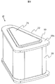
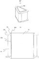
- FIG. 2 shows the configuration of the core member 20 for one slot.
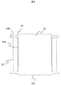
- FIG. 3 shows a radial cross-sectional view of the core member 20.
- the bobbin 22 is formed of resin. Both ends of the cylindrical portion 22a are open.
- the inner cylindrical portion of the cylindrical portion 22a has an inner diameter that approximately matches the outer diameter of the iron core 21 having a substantially trapezoidal shape.
- the coil 23 is wound around the outer tube portion of the tube portion 22a. In the first embodiment, the cylindrical portion 22 a is shorter than the length of the iron core 21.
- a flange portion 22b extending a predetermined length from the outer cylindrical portion over the entire circumference in the vertical direction.
- the predetermined length is preferably longer than the width of the wound coil 23. This is for insulation between the coils 23 and the inner periphery of the housing. Further, the predetermined length does not have to be uniform in the entire region of the flange portion 22b, and can be appropriately changed according to the design, such as further increasing the length of the rotating shaft side or the housing side.
- the flange portion 22b protrudes in the rotation axis direction (extension direction of the inner cylinder portion) so as to surround the inner cylinder portion opening (inside the bobbin 22). Protrusion 10 provided continuously around the cylinder opening).
- each protruding portion 10 formed on both flange portions 22 b protrudes lower than the protruding portion of the iron core 21. That is, both ends of the iron core 21 protrude from the bobbin 22.
- the inner peripheral surface on the inner edge side of the protruding portion 10 is opposed to the outer peripheral side surface of the iron core 21 and is in contact with each other.
- the winding jig of the winding machine supports the protruding portion 10 without supporting the iron core 21.
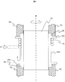
- FIG. 4 is a side sectional view schematically showing how the coil 23 is wound around the core member 20.
- the iron core jigs 51 and 52 hold the protruding portion 10 of the bobbin 22 in which the iron core 21 is inserted from both sides.
- the jig is in contact with the surfaces of the protrusion 22 and the flange 22b.
- the jig is rotated by the winding axis B, and at the same time, tension F is applied to the coil 23, and the coil 23 is wound so as to be in close contact with the cylindrical portion 22a.
- the coil 23 is supplied from a movable nozzle, and is wound for an arbitrary number of stages by moving the nozzle up and down.
- the insertability of the iron core does not deteriorate due to the deformation of the cylindrical portion 22a by the coil 23.
- the protruding portion 10 of the bobbin 22 is held by a jig, so that the coil 23 can be applied regardless of the strength of the iron core 21. Therefore, it can be safely wound around a core material with low rigidity, such as amorphous metal, fine met, and a dust core.
- the load of the winding jig is received by the protruding portion 10 arranged on the innermost periphery of the bobbin, the torque on the contact surface can be minimized. As a result, the strength of the bobbin necessary for holding can be ensured by increasing the minimum amount of resin, and the amount of material used can be reduced.
- the protrusion part 10 exists on extension of the cylinder part 22a, the stress with respect to the cylinder part 22a direction is strong. That is, since the supporting force of the winding jig with respect to the bobbin 22 can be increased, even if the tension F applied to the coil 23 is increased, there is no problem in winding the coil. As a result, the coils 23 and the cylindrical portion 22a and the coil 23 can be brought into closer contact with each other, the coil 23 can be densified, and more windings can be disposed in a predetermined region. High output and high efficiency can be achieved.
- the winding jigs 51 and 52 support not only the protrusion 10 but also a part of the surface of the flange 22b, the winding jigs 51 and 52 are increased in the direction between the flanges 22b that increases as the coil 23 is wound. The stress to the spread can be achieved, and the effect of preventing the bobbin from being damaged can be expected.
- the winding jigs 51 and 52 are configured to support the protruding portion 10 and a part of the flange portion 22b, but do not contact the surface of the flange portion 22b. Further, only the outer periphery may be held.
- the bobbin 22 of the second embodiment is characterized in that the horizontal position (position in the rotation axis direction) of at least the end face of the protruding portion 10 on one side and the end face of the iron core 21 coincide.
- 2nd Embodiment is described, about the location same as 1st Embodiment, the same code
- FIG. 5 schematically shows the resin molding process.
- a housing 40 is inserted into a lower mold 62 having substantially the same inner diameter, and a cylindrical middle mold 61 for forming an axial core space through which a rotating shaft passes later from an opening on the opposite side of the housing 40.
- the core member 20 is arranged in an annular shape around the middle mold, and then an upper mold (not shown) is inserted from the housing opening opposite to the lower mold 62 and supports the core member 20 with the core member 20 interposed therebetween. Thereafter, the resin is sealed from the opposed surfaces of the upper mold and the lower mold 62.
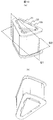
- FIG. 6A is a perspective view showing the configuration of the core member 20 according to the second embodiment.
- FIG. 6B shows a cross section in the rotation axis direction of the core member 20.
- the protruding portion 10 surrounds the entire outer periphery of the end portion of the iron core 21 protruding from the cylindrical portion 22 a, and further, the horizontal position (rotation) between the top of the protruding portion 10 and the end surface of the iron core 21.
- the position in the axial direction is substantially the same.
- the example in which the end surface of the protruding portion 10 and the end surface of the iron core 21 coincide with each other is shown. It may be only one side. If the axial length of the bobbin 22 including the projecting portion 10 is designed to be shorter than the axial length of the iron core 21, it is possible to prevent the bobbin axial length from becoming longer than the iron core due to machining intersection. This ensures that a spatial gap between the rotor 30 and the stator 19 is ensured by making the stator shaft length coincide with the iron core shaft length, and avoids contact between the rotor 30 and the stator 19. can do.
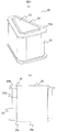
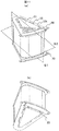
- FIG. 7A is a perspective view of the core member 20 for one slot of the motor 1 according to the third embodiment
- FIG. 7B is a cross-sectional view of the core member 20 in the direction of the rotation axis A.
- symbol is used and description is abbreviate
- the protruding portion 10 has an inner diameter that extends in the extending direction of the cylindrical portion 22a and has a larger diameter than the inner diameter extension line of the cylindrical portion 22a. That is, the inner peripheral surface of the protruding portion 10 is in a state of being separated by a predetermined width from an extension line extending from the inner periphery of the cylindrical portion 22a.
- the predetermined width for example, it is preferable to be equivalent to the tip width of an iron core insertion jig, which will be described later, but when the taper is formed from the inner peripheral surface of the protruding portion 10 to the inner periphery of the cylindrical portion 22b, This is not a limitation.
- the groove 10b is formed between the protruding portion 10 and the outer periphery of the protruding portion of the iron core 21.
- the groove 10b mainly has a function of ensuring the insertion of the iron core 21.
- FIG. 8 shows an example of a process for inserting the iron core 21 into the bobbin 22.
- the iron core 21 supported by the insertion jig 71 is inserted into the one opening side of the bobbin 22 from the other end of the bobbin 22 placed on the base 72 of the iron core insertion jig. .
- the insertion jig 71 sandwiches the stacked iron cores 21 from both sides in the stacking direction and the other two directions.
- the tip of the insertion jig 71 has a spire shape and is disposed so as to face the bottom surface of the groove 10b. In this state, the iron core 21 is pressurized in the vertical direction and inserted into the bobbin 22.
- the bobbin 22 and the insertion jig 71 can be facilitated. Moreover, since it positions in the position nearest to the insertion surface 21a of the iron core 21, it has high positioning accuracy. As a result, the workability of inserting the iron core is greatly improved, and the yield at the time of insertion can be improved.
- the groove 10b is provided on the entire circumference is shown, but a part of the groove 10b may be provided. The groove 10b may be provided in the protruding portions 10 on both sides.
- the protruding portion 10 is configured to be provided at a part of the protruding portion of the iron core 21.
- the protruding portion 10 is formed discontinuously along the inner edge of the cylindrical portion 22a.
- the iron core 21 has a laminated iron core configuration of thin plates or foil strips, it is preferable that individual plate pieces can be held. In addition, it can be said that if a part of the iron core protruding portion is exposed from the heat dissipation surface of the iron core 21, it is advantageous.
- FIG. 9A shows a perspective view of the core member 20 for one slot of the motor 1 according to the fourth embodiment
- FIG. 9B shows a perspective view of the core member 20 viewed from the bottom side.
- symbol is used and description is abbreviate
- the protrusion 10 is provided so that the left and right are asymmetric with respect to the axial rotation direction. Specifically, a gap portion 10 c is provided in the axial rotation direction of the protruding portion 10 with respect to 1. Similarly, the protrusion 10 is provided so as to be asymmetrical in the axial direction.
- the outer peripheral portion of the iron core 21, which is the position of the gap 10c, is in direct contact with the mold resin.
- the horizontal direction position of the top part of the protrusion part 10 and the end surface of the iron core 21 is the same as that of 2nd and 3rd embodiment.
- the plate pieces constituting the iron core 21 are in direct contact with the resin on either the left or right side, and the holding strength of the plate pieces and the holding strength of the iron core 21 are improved. Furthermore, the heat of the iron core 21 is easily conducted to the resin side by the gap 10c, and a heat dissipation effect can be expected. Needless to say, as with the other embodiments described above, the coil 23 also has an effect on the insertion surface and a positioning effect.
- the gap 10c is provided symmetrically in the rotational direction with respect to the central cross section S1 in the axial direction, and is provided asymmetrically in the vertical direction with respect to the radial cross section S2. It may be configured.
- the protruding portions 10 are arranged so as to surround the four corners of the iron core 21 having a substantially trapezoidal shape.
- the side provided with the protruding portions 10 at these four corners functions advantageously as a guide for the insertion jig of the iron core 21, and the effect of facilitating the positioning of the insertion jig and the bobbin can be expected.
- the protruding portion 10 is non-target in the S2 cross section, an effect that the heat radiation effect can be expected to be dispersed at the top and bottom can be expected.
- FIG. 11A shows a perspective view of the core member 20 for one slot of the motor 1 according to the modified example 2
- FIG. 11B shows a perspective view of the core member 20 viewed from the bottom side.
- symbol is used and description is abbreviate
- the bobbin 22 of the modified example 2 has a configuration in which the protruding portion 10 is provided on the housing side corner of the iron core 21 on any opening side of the bobbin 22 in addition to the configuration of the protruding portion 10 of the modified example 1. That is, as shown in FIG. 11B, the protrusions 10 are also provided on the corners of the housing 40 on the bottom surface side of the bobbin 22 (hereinafter, these two protrusions are particularly referred to as “protrusion 11”). . Further, as shown in the bottom view of the core member 20 in FIG. 12, the protruding portion 11 is provided with a gap from the housing side corner of the iron core 21 so that the resin enters.
- the plurality of core members 20, the stator 19 including these members, and the inner periphery of the housing 40 are integrally formed by resin molding.
- the resin applied on the flange 22b is relatively thin because the iron core 21 has a thickness that protrudes from the bobbin 22.
- a conductive member 13 made of a conductive metal or the like is disposed on the surface of the flange portion 22b on the housing 40 side.
- the conductive member 80 is thinner than the portion where the iron core 21 protrudes from the bobbin 22, and is entirely covered with mold resin.
- the conductive member 80 is electrically connected to the inner periphery of the housing 40 and has a function of reducing the capacitance between the coil 23 and the rotor 30.
- the conductive member 13 also has a function as a heat sink of the core member 20.
- the modified example 2 is provided with the protruding portion 11 on the outer peripheral side (housing inner peripheral side) of the core corner portion, the progress of the crack can be stopped even if a crack due to the periphery of the corner portion of the iron core 21 occurs. A decrease in strength and heat dissipation can be suppressed. Moreover, since the clearance gap is provided between the protrusion part 11 and the core, the resin which entered the clearance gap can also prevent the iron core 21 from coming off in the axial direction.
- the protruding portion 10 that faces the housing side corner of the iron core 21 exhibits the same function as the protruding portion 11.
- a gap may also be provided between the protruding portion 10 and the iron core 21, but if the protruding portion 10 is in contact with the iron core 21 as in this example, the insertion jig at the time of inserting the iron core is used. It is effective as a guide. That is, the protruding portion 10 of the one flange portion 22b has a function as a bobbin insertion guide, and the protruding portion 11 of the other flange portion 22b has convenience and function of preventing the core from falling off and improving the resin durability. It is the structure which has the property.
- the bobbin 22 in each of the above embodiments is formed from an insulating resin and is manufactured by resin molding.
- each embodiment is not limited to this, and can be manufactured by a three-dimensional modeling machine or the like described below. That is, the bobbin 22 itself can be manufactured not only by a three-dimensional modeling machine but also by manufacturing a mold for resin molding by layer modeling with a three-dimensional modeling machine or by cutting with a cutting RP device. 22 can be obtained.
- an additive manufacturing method an optical modeling method, a powder sintering additive manufacturing method, an ink jet method, a resin dissolution lamination method, a gypsum powder method, a sheet molding method, a film transfer image lamination method, a metal optical modeling composite processing method, and the like can be applied.
- the data for additive manufacturing and cutting is generated by processing 3D data generated by CAD, CG software, or a 3D scanner into NC data by CAM. Three-dimensional modeling is performed by inputting the data to a three-dimensional modeling machine or a cutting RP device. Note that NC data may be directly generated from 3D data by CAD / CAM software.
- a data provider or servicer who created 3D data or NC data can be distributed in a predetermined file format via a communication line such as the Internet, and the user
- a communication line such as the Internet
- the data provider it is also possible for the data provider to record 3D data or NC data on a non-volatile recording medium and provide it to the user.
- the cylindrical part which consists of the outer cylinder which winds the inner cylinder and coil which have the substantially trapezoidal cross section which inserts an iron core, and both opening of the said cylindrical part A flange extending in the vertical direction from the entire circumference of the outer cylinder in the vicinity of the end, and at least part of the inner edge on the outer surface of at least one of the flanges and closer to the inner edge of the inner cylinder
- a three-dimensional modeling machine based on three-dimensional data of a bobbin for a rotating electrical machine having a protruding portion that further extends in the extending direction of the inner cylinder.
- the cylinder part which consists of the inner cylinder which has a substantially trapezoidal cross section which inserts an iron core, and the outer cylinder which winds a coil
- Both the opening ends of the said cylinder part A flange extending in the vertical direction with a predetermined width from the entire circumference of the outer cylinder, and at least part of the inner edge on the outer surface of at least one of the flanges and closer to the inner edge of the inner cylinder.
- a synchronous reluctance motor, a switched reluctance motor, an induction motor, or the like that does not include the permanent magnet 31 in the rotor 30 may be used.
- a generator may be used instead of a motor.
- the rotor 30 may be provided with a back yoke between the permanent magnet 31 and the yoke 32.
- the approximate trapezoidal shape of the end face shape of the iron core 21 is more like a fan shape or a cross section having a streamline in the axial rotation direction.
- the planes of the stator 19 and the rotor 30 that face each other are not necessarily limited to passing through an air gap in a direction perpendicular to the shaft center, and each of the rotation shafts is within a range that does not depart from the purpose of the axial gap motor.
- a configuration in which a certain inclination occurs in the direction may be used.
- a punching taper or corner R necessary for molding the bobbin with a mold may be provided separately.
- the shape of the protrusions 10 and 11 only needs to protrude in the rotation axis direction on the outer peripheral side of the portion where the iron core 21 protrudes from the bobbin 22.
- SYMBOLS 1 Double rotor type axial air gap type permanent magnet synchronous motor (motor), 10 ... Projection part, 10a ... Bottom surface, 10b ... Groove, 10c ... Gap part, 11 ... Projection part, 19 ... Stator, 20 ... Core member, DESCRIPTION OF SYMBOLS 21 ... Iron core, 22 ... Bobbin, 22a ... Cylindrical part, 22b ... Gutter part, 23 ... Coil, 30 ... Rotor, 31 ... Permanent magnet, 32 ... Yoke, 40 ... Housing, 51, 52 ... Coil winding jig, 61 ... Middle mold, 62 ... Lower mold, 71 ... Inserting jig, 72 ... Pedestal, 80 ... Conductive member, 90 ... Crack, A ... Rotating shaft, B ... Winding shaft, F ... Tension, S1 ... Radial section , S2 ... Rotational axis direction cross section
Landscapes
- Engineering & Computer Science (AREA)
- Power Engineering (AREA)
- Insulation, Fastening Of Motor, Generator Windings (AREA)
- Iron Core Of Rotating Electric Machines (AREA)
- Permanent Magnet Type Synchronous Machine (AREA)
Abstract
Description
特許文献1は、アキシャルエアギャップ型回転電機のコイルの巻線方法及びコイルの製造方法を開示する。ここでは、所定幅を有する所定の軸にコイルを巻き付けており、鍔部を有する鉄心に直接巻き付ける方法や、鍔部を有するボビンに巻き付ける方法が示されている。また、特許文献2は、ボビン内に鉄心を挿入した状態で、ボビンを軸方向に直結して連続巻きする方法を開示する。
アキシャルエアギャップ型回転電機の小型化を実現しつつ信頼性を確保する構成が望まれる。
上記した以外の課題、構成及び効果は、以下の記載からより明らかになる。
以下、図面を用いて本発明を実施するための形態を説明する。図1に、本発明を適用した第1実施形態であるアキシャルエアギャップ型モータ1(以下、単に、「モータ1」という場合がある。)による電機子の概要構成を示す。モータ1は、ダブルロータ型のアキシャルエアギャップ型モータの例である。
また、巻線時には、ボビン22の特に、突出部10を治具で保持するため、鉄心21の強度によらずコイル23を施すことができる。したがって、アモルファス金属やファインメット、圧粉磁心等の剛性の低いコア材にも安全に巻き回すことができる。
第2実施形態のボビン22は、少なくとも片側の突出部10の端面と、鉄心21の端面との水平方向位置(回転軸方向の位置)が一致することを特徴の一つとする。以下、第2実施形態を説明するが、第1実施形態と同一の箇所に関しては同一符号を用い、説明を省略する。
第3実施形態のモータ1は、突出部10と、鉄心21との間の全周に渡って溝10bが設けられる構成であることを特徴の一つとする。
図7(a)に、第3実施形態によるモータ1の1スロット分のコアメンバ20の斜視図を示し、図7(b)に、コアメンバ20の回転軸A方向断面図を示す。なお、第1実施形態と同一の箇所に関しては同一符号を用い、説明を省略する。
なお、本実施例では,溝10bを全周に設けた例を示したが、一部であってもよい。溝10bは、両側の突出部10に設けてもよい。
第4実施形態のモータ1は、突出部10が、鉄心21の突出部分の一部に設けられる構成である点を特徴の一つとする。換言すると、突出部10が、筒部22aの内縁にそって不連続に形成されるようになっている。
なお、上記他の実施形態と同様に、コイル23の挿入面での効果や位置決め効果も兼ね備えるのは言うまでもない。
図10(a)、(b)に示すように、間隙部10cは、軸心方向の中心断面S1を基準に回転方向に対称に設け、径方向の断面S2を基準に、上下で非対称に設ける構成でもよい。特に、図10の例では、概略台形形状を有する鉄心21の四隅を囲むように突出部10を配置する構成である。これら四隅の突出部10を設けた側が、鉄心21の挿入治具の案内として有利に機能し、挿入治具とボビンとの位置決めが容易になるという効果も期待できる。更に、突出部10がS2断面で非対象となっていることで、上下で放熱効果を期待できる部分が分散させることができるという効果も期待できる。
第4実施形態の変形例2によるモータ1は、上記他の実施形態の機能を備えつつ、更に固定子19にモールドした樹脂の保守機能を有する点を特徴の一つとする。
図11(a)に、変形例2によるモータ1の1スロット分のコアメンバ20の斜視図を示し、図11(b)に、コアメンバ20を底面側からみた斜視図を示す。なお、第1実施形態と同一の箇所に関しては同一符号を用い、説明を省略する。
最後に、上記実施形態によるボビン22の製造方法について述べる。上記各実施形態のボビン22は、絶縁性を有する樹脂から形成されるものであり、樹脂成形によって製造されるものである。しかしながら、各実施形態はこれに限定されるものではなく、以下に示す三次元造形機等によって、製造することも可能である。即ちボビン22そのものを三次元造形機で製造するのみならず樹脂成形用の金型を、三次元造形機で積層造形したり、切削RP装置によって切削加工したりすることで得る製造することでもボビン22を得ることができる。
例えば、上記例では、ダブルロータ型且つ永久磁石同期モータの例を説明したが、シングルロータ型であっても適用することができる。この場合、突出部10が、ボビンの鍔部22bの一方開口部側にのみ設けられていてもよい。
また、回転子30には,永久磁石31と、ヨーク32との間にバックヨークを設けてもよい。鉄心21の端面形状の概略台形には、扇形や軸回転方向に流線形を有する断面でもより。また、対向する固定子19と、回転子30との平面も、必ずしも軸芯から鉛直な方向のエアギャップを介することに限定されず、アキシャルギャップモータとしての趣旨を逸脱しない範囲で、夫々回転軸方向に一定の傾きが生じる構成であってもよい。
Claims (17)
- 概略台形の端面を有する柱体形状からなる鉄心、該鉄心外周方向に巻き回したコイル及び前記鉄心と前記コイルとの間に配置されたボビンを有する複数のコアメンバが、回転軸を中心に環状に配列してなる固定子と、回転軸径方向に所定のエアギャップを介して、前記鉄心の端面と面対向する回転子とを有するアキシャルエアギャップ型回転電機であって、
前記ボビンが、
前記鉄心の外周側面に対向し、前記鉄心の長さよりも短い筒部と、前記筒部の両端部近傍に、該筒部の外周から鉛直方向外側に所定長さ延伸した鍔部と、
少なくとも一方の前記鍔部の外側表面上且つ前記筒部の内縁寄りに、挿入された前記鉄心の端部外周側面と対向する内周面を有すると共に前記筒部の延伸方向に更に突出する突出部とを有するものであるアキシャルエアギャップ型回転電機。 - 請求項1に記載のアキシャルエアギャップ型回転電機であって、
挿入された前記鉄心の端部外周側面と、前記突出部の内周面とが接触するものであるアキシャルエアギャップ型回転電機。 - 請求項1に記載のアキシャルエアギャップ型回転電機であって、
前記突出部の頭頂部と、前記鉄心の端面との回転軸方向の位置が位置するものであるアキシャルエアギャップ型回転電機。 - 請求項1に記載のアキシャルエアギャップ型回転電機であって、
前記突出部の内周面が、前記内筒部内周の延伸方向延長線から所定幅離間したものである回転電機用ボビン。 - 請求項1に記載のアキシャルエアギャップ型回転電機であって、
前記突出部が、前記筒部の内縁の全周に沿って連続して設けられるものであるアキシャルエアギャップ型回転電機。 - 請求項1に記載のアキシャルエアギャップ型回転電機であって、
前記突出部が、前記筒部の内縁に沿って不連続に設けられるものであるアキシャルエアギャップ型回転電機。 - 請求項6に記載のアキシャルエアギャップ型回転電機であって、
前記突出部が、回転軸回転方向の互いに対向しない位置に不連続に設けられるものであるアキシャルエアギャップ型回転電機。 - 請求項6に記載のアキシャルエアギャップ型回転電機であって、
前記突出部が、回転軸回転方向で互いに対向する位置に不連続に設けられるものであるアキシャルエアギャップ型回転電機。 - 請求項6に記載のアキシャルエアギャップ型回転電機であって、
不連続に配置される前記突出部が、前記概略台形の端面を有する鉄心の四隅の外周側面と対向する前記内周面を有するものを含むものであるアキシャルエアギャップ型回転電機。 - 請求項6に記載のアキシャルエアギャップ型回転電機であって、
前記突出部が、両方の鍔部に配置されるものであり、
前記一方鍔部の突出部と、他方端部の突出部とが、回転軸方向で対向しない位置に不連続に配置されるものであるアキシャルエアギャップ型回転電機。 - 請求項6に記載のアキシャルエアギャップ型回転電機であって、
不連続に設けられる前記突出部が、前記概略台形形状を有する鉄心の下底側の2つの角夫々の近傍に、該角と所定の間隙をもって対向する突出部を更に有するものであるアキシャルエアギャップ型回転電機。 - 請求項1~11の何れか一項に記載のアキシャルエアギャップ型回転電機であって、
前記複数のコアメンバが、樹脂モールドによって一体的に形成されるものであるアキシャルエアギャップ型回転電機。 - 請求項1~11の何れか一項に記載のアキシャルエアギャップ型回転電機であって、
前記複数のコアメンバ夫々と、前記固定子及び回転子を内包するハウジングの内周とが、樹脂モールドによって一体的に形成されるものであるアキシャルエアギャップ型回転電機。 - 請求項1~11の何れか一項に記載のアキシャルエアギャップ型回転電機であって、
前記鉄心が、磁性体材料が含有された鋼板片を回転軸径方向に積層してなるものであるアキシャルエアギャップ型回転電機。 - 鉄心を挿入する概略台形の断面を有する内筒及びコイルを巻き回す外筒からなる筒部と、
前記筒部の両開口端部近傍に、前記外筒の全周から所定幅鉛直方向に延伸する鍔部と、
少なくとも一方の前記鍔部の外側表面上且つ前記内筒の内縁寄りに、該内縁の少なくとも一部に沿って前記内筒の延伸方向に更に延伸する突出部と、
を有する回転電機用ボビン。 - 請求項15に記載の回転電機用ボビンであって、
前記突出部の前記内筒側の側面と、前記内筒の内周面とが連続的に形成されたものである回転電機用ボビン。 - 請求項14に記載の回転電機用ボビンであって、
前記突出部の前記内筒側の側面が、前記内筒の延伸方向の延長線と所定幅離間するものである回転電機用ボビン。
Priority Applications (6)
| Application Number | Priority Date | Filing Date | Title |
|---|---|---|---|
| CN201480080050.3A CN106663980B (zh) | 2014-04-21 | 2014-04-21 | 轴向气隙型旋转电机及旋转电机用绕线架 |
| US15/305,499 US10454325B2 (en) | 2014-04-21 | 2014-04-21 | Axial air gap rotating electric machine and rotating electric machine bobbin |
| JP2016514556A JP6294471B2 (ja) | 2014-04-21 | 2014-04-21 | アキシャルエアギャップ型回転電機及び回転電機用ボビン |
| EP14889869.5A EP3136552B1 (en) | 2014-04-21 | 2014-04-21 | Axial air gap rotating electric machine and rotating electric machine bobbin |
| PCT/JP2014/061117 WO2015162655A1 (ja) | 2014-04-21 | 2014-04-21 | アキシャルエアギャップ型回転電機及び回転電機用ボビン |
| TW104103619A TWI583109B (zh) | 2014-04-21 | 2015-02-03 | Axial air gap type rotary motor and rotary tube with rotating electrical machine |
Applications Claiming Priority (1)
| Application Number | Priority Date | Filing Date | Title |
|---|---|---|---|
| PCT/JP2014/061117 WO2015162655A1 (ja) | 2014-04-21 | 2014-04-21 | アキシャルエアギャップ型回転電機及び回転電機用ボビン |
Publications (1)
| Publication Number | Publication Date |
|---|---|
| WO2015162655A1 true WO2015162655A1 (ja) | 2015-10-29 |
Family
ID=54331853
Family Applications (1)
| Application Number | Title | Priority Date | Filing Date |
|---|---|---|---|
| PCT/JP2014/061117 Ceased WO2015162655A1 (ja) | 2014-04-21 | 2014-04-21 | アキシャルエアギャップ型回転電機及び回転電機用ボビン |
Country Status (6)
| Country | Link |
|---|---|
| US (1) | US10454325B2 (ja) |
| EP (1) | EP3136552B1 (ja) |
| JP (1) | JP6294471B2 (ja) |
| CN (1) | CN106663980B (ja) |
| TW (1) | TWI583109B (ja) |
| WO (1) | WO2015162655A1 (ja) |
Cited By (3)
| Publication number | Priority date | Publication date | Assignee | Title |
|---|---|---|---|---|
| CN108781017A (zh) * | 2017-01-27 | 2018-11-09 | 株式会社日立产机系统 | 轴向间隙型旋转电机及其制造方法 |
| TWI699074B (zh) * | 2017-09-29 | 2020-07-11 | 日商日立金屬股份有限公司 | 徑向間隙式旋轉電機及其製造方法、旋轉電機用齒片的製造裝置、旋轉電機用齒構件的製造方法 |
| JP2021065096A (ja) * | 2021-01-12 | 2021-04-22 | 株式会社日立産機システム | アキシャルギャップ型回転電機 |
Families Citing this family (14)
| Publication number | Priority date | Publication date | Assignee | Title |
|---|---|---|---|---|
| CN109478809B (zh) * | 2017-01-31 | 2020-09-18 | 株式会社日立产机系统 | 轴向间隙型旋转电机 |
| FR3076674B1 (fr) * | 2018-01-09 | 2022-03-04 | Whylot Sas | Moteur ou generatrice electromagnetique a deux rotors et quatre stators et systeme de refroidissement integre |
| CN108173362A (zh) * | 2018-01-10 | 2018-06-15 | 上海硅泰电子有限公司 | 无轭部定子铁芯盘式电机的定子组件以及盘式电机 |
| WO2020235713A1 (ko) * | 2019-05-21 | 2020-11-26 | 엘지전자 주식회사 | 분할코어조립체 및 이를 포함하는 스테이터 |
| DE102020101149A1 (de) * | 2019-12-04 | 2021-06-10 | Schaeffler Technologies AG & Co. KG | Axialflussmaschine mit mechanisch fixierten Statorkernen mit radial verlaufenden Blechsegmenten |
| JP7866827B2 (ja) * | 2021-02-22 | 2026-05-28 | 山洋電気株式会社 | モータの電機子構造及びその製造方法 |
| CA3203040A1 (en) * | 2021-03-31 | 2022-10-06 | Tesshu Murakawa | Rotating electrical machine, stator core and rotor core set, method for manufacturing rotating electrical machine, method for manufacturing non-oriented electrical steel sheet for stator and non-oriented electrical steel sheet for rotor, method for manufacturing stator and rotor, and non-oriented electrical steel sheet se |
| US11646611B2 (en) | 2021-07-28 | 2023-05-09 | GM Global Technology Operations LLC | Locking mechanism for segmented stator core |
| JP7754652B2 (ja) * | 2021-07-28 | 2025-10-15 | ニデックアドバンスドモータ株式会社 | ステータ、モータ及びファン |
| US11689073B2 (en) | 2021-08-13 | 2023-06-27 | GM Global Technology Operations LLC | Rotor core design |
| US20230047862A1 (en) * | 2021-08-13 | 2023-02-16 | GM Global Technology Operations LLC | Segmented stator core design |
| RU210261U1 (ru) * | 2021-11-29 | 2022-04-04 | Общество С Ограниченной Ответственностью Научно-Производственное Предприятие "Томская Электронная Компания" | Торцевая электрическая машина |
| CN116707174A (zh) * | 2022-02-28 | 2023-09-05 | 通用汽车环球科技运作有限责任公司 | 包括带有smc部件和具有锁定机构的层压部件的混合定子芯的轴向磁通电机 |
| US12571368B2 (en) | 2023-04-10 | 2026-03-10 | David Barr Miller | Vertical-axis wind turbine systems and devices |
Citations (3)
| Publication number | Priority date | Publication date | Assignee | Title |
|---|---|---|---|---|
| JP2005051929A (ja) * | 2003-07-29 | 2005-02-24 | Fujitsu General Ltd | 電動機 |
| JP2010088142A (ja) * | 2008-09-29 | 2010-04-15 | Daikin Ind Ltd | インシュレータ及び電機子コア |
| JP2013135541A (ja) * | 2011-12-27 | 2013-07-08 | Hitachi Industrial Equipment Systems Co Ltd | アキシャルギャップ回転電機 |
Family Cites Families (9)
| Publication number | Priority date | Publication date | Assignee | Title |
|---|---|---|---|---|
| JPH0350736U (ja) * | 1989-09-25 | 1991-05-17 | ||
| JPH0727819B2 (ja) * | 1990-06-21 | 1995-03-29 | 三菱電機株式会社 | 電磁石装置 |
| GB2307947B (en) * | 1995-12-08 | 1999-08-18 | Aisan Ind | Magnetically coupled pump |
| JP2001054270A (ja) * | 1999-08-05 | 2001-02-23 | Sankyo Seiki Mfg Co Ltd | 面対向型モータ |
| US6798091B2 (en) * | 2001-11-29 | 2004-09-28 | Sanyo Denki Co., Ltd. | Watertight brushless fan motor |
| NO318885B1 (no) * | 2003-05-14 | 2005-05-18 | Smart Motor As | Anordning ved elektrisk maskin |
| JP2005348547A (ja) * | 2004-06-04 | 2005-12-15 | Nissan Motor Co Ltd | アキシャルギャップ型回転電機のインシュレータ |
| JP4816879B2 (ja) | 2005-06-30 | 2011-11-16 | 株式会社富士通ゼネラル | アキシャルエアギャップ型電動機 |
| JP5320676B2 (ja) * | 2007-01-26 | 2013-10-23 | ダイキン工業株式会社 | コイルの製造方法、電機子の製造方法 |
-
2014
- 2014-04-21 WO PCT/JP2014/061117 patent/WO2015162655A1/ja not_active Ceased
- 2014-04-21 US US15/305,499 patent/US10454325B2/en active Active
- 2014-04-21 JP JP2016514556A patent/JP6294471B2/ja active Active
- 2014-04-21 EP EP14889869.5A patent/EP3136552B1/en active Active
- 2014-04-21 CN CN201480080050.3A patent/CN106663980B/zh active Active
-
2015
- 2015-02-03 TW TW104103619A patent/TWI583109B/zh active
Patent Citations (3)
| Publication number | Priority date | Publication date | Assignee | Title |
|---|---|---|---|---|
| JP2005051929A (ja) * | 2003-07-29 | 2005-02-24 | Fujitsu General Ltd | 電動機 |
| JP2010088142A (ja) * | 2008-09-29 | 2010-04-15 | Daikin Ind Ltd | インシュレータ及び電機子コア |
| JP2013135541A (ja) * | 2011-12-27 | 2013-07-08 | Hitachi Industrial Equipment Systems Co Ltd | アキシャルギャップ回転電機 |
Cited By (6)
| Publication number | Priority date | Publication date | Assignee | Title |
|---|---|---|---|---|
| CN108781017A (zh) * | 2017-01-27 | 2018-11-09 | 株式会社日立产机系统 | 轴向间隙型旋转电机及其制造方法 |
| JPWO2018138858A1 (ja) * | 2017-01-27 | 2019-04-11 | 株式会社日立産機システム | アキシャルギャップ型回転電機及びその製造方法 |
| CN108781017B (zh) * | 2017-01-27 | 2021-08-27 | 株式会社日立产机系统 | 轴向间隙型旋转电机及其制造方法 |
| TWI699074B (zh) * | 2017-09-29 | 2020-07-11 | 日商日立金屬股份有限公司 | 徑向間隙式旋轉電機及其製造方法、旋轉電機用齒片的製造裝置、旋轉電機用齒構件的製造方法 |
| JP2021065096A (ja) * | 2021-01-12 | 2021-04-22 | 株式会社日立産機システム | アキシャルギャップ型回転電機 |
| JP7233451B2 (ja) | 2021-01-12 | 2023-03-06 | 株式会社日立産機システム | アキシャルギャップ型回転電機 |
Also Published As
| Publication number | Publication date |
|---|---|
| EP3136552A4 (en) | 2017-12-06 |
| EP3136552B1 (en) | 2020-02-12 |
| US20170187252A1 (en) | 2017-06-29 |
| JP6294471B2 (ja) | 2018-03-14 |
| CN106663980B (zh) | 2020-04-24 |
| US10454325B2 (en) | 2019-10-22 |
| JPWO2015162655A1 (ja) | 2017-04-13 |
| CN106663980A (zh) | 2017-05-10 |
| EP3136552A1 (en) | 2017-03-01 |
| TWI583109B (zh) | 2017-05-11 |
| TW201541819A (zh) | 2015-11-01 |
Similar Documents
| Publication | Publication Date | Title |
|---|---|---|
| JP6294471B2 (ja) | アキシャルエアギャップ型回転電機及び回転電機用ボビン | |
| JP5879121B2 (ja) | アキシャルギャップ回転電機 | |
| CN107005103B (zh) | 旋转电机用定子铁芯、旋转电机及旋转电机的制造方法 | |
| JP6584331B2 (ja) | 単相ブラシレスモータおよび単相ブラシレスモータの製造方法 | |
| WO2014208110A1 (ja) | アキシャル型回転電機 | |
| CN109478813B (zh) | 轴向间隙型旋转电机 | |
| WO2015145901A1 (ja) | アキシャルエアギャップ型電動機及び電動機用ボビン | |
| JP7271796B2 (ja) | 固定子及び回転電機並びに回転電機の製造方法 | |
| JP6462714B2 (ja) | アキシャルギャップ型回転電機及び絶縁部材 | |
| WO2017149685A1 (ja) | アキシャルギャップ型回転電機及び回転電機固定子用ボビン | |
| CN109478809B (zh) | 轴向间隙型旋转电机 | |
| JP6375370B2 (ja) | アキシャルエアギャップ型回転電機 | |
| JP2016116421A (ja) | 回転電機 | |
| JP2008236862A (ja) | ロータコアとロータおよびそれを用いた回転機 | |
| CN113924712B (zh) | 旋转电机及制造定子核心的方法 | |
| JP2009060754A (ja) | ステータ用コア、ステータ、その組立方法およびモータ | |
| JP6824348B2 (ja) | 単相ブラシレスモータ、単相ブラシレスモータの製造方法、単相ブラシレスモータを備えた電気掃除機、および電気掃除機の製造方法 | |
| JP2014225935A (ja) | 永久磁石式回転電機 | |
| JP2015027175A (ja) | 回転電機及び回転電機の製造方法 | |
| JP2008022646A (ja) | 永久磁石型モータ用固定子、永久磁石型モータ、およびその固定子の製造方法 | |
| CN106415994A (zh) | 轴向气隙型电动机 | |
| JP2012105543A (ja) | 電動機の固定子 | |
| JP6595033B2 (ja) | アキシャルエアギャップ型回転電機 | |
| JP5271991B2 (ja) | 回転電機の固定子 | |
| JP6685166B2 (ja) | アキシャルギャップ型回転電機 |
Legal Events
| Date | Code | Title | Description |
|---|---|---|---|
| 121 | Ep: the epo has been informed by wipo that ep was designated in this application |
Ref document number: 14889869 Country of ref document: EP Kind code of ref document: A1 |
|
| ENP | Entry into the national phase |
Ref document number: 2016514556 Country of ref document: JP Kind code of ref document: A |
|
| NENP | Non-entry into the national phase |
Ref country code: DE |
|
| REEP | Request for entry into the european phase |
Ref document number: 2014889869 Country of ref document: EP |
|
| WWE | Wipo information: entry into national phase |
Ref document number: 2014889869 Country of ref document: EP |
|
| WWE | Wipo information: entry into national phase |
Ref document number: 15305499 Country of ref document: US |