WO2015162725A1 - 非接触受電装置の車載構造 - Google Patents
非接触受電装置の車載構造 Download PDFInfo
- Publication number
- WO2015162725A1 WO2015162725A1 PCT/JP2014/061444 JP2014061444W WO2015162725A1 WO 2015162725 A1 WO2015162725 A1 WO 2015162725A1 JP 2014061444 W JP2014061444 W JP 2014061444W WO 2015162725 A1 WO2015162725 A1 WO 2015162725A1
- Authority
- WO
- WIPO (PCT)
- Prior art keywords
- power receiving
- side coil
- receiving side
- vehicle
- coil unit
- Prior art date
- Legal status (The legal status is an assumption and is not a legal conclusion. Google has not performed a legal analysis and makes no representation as to the accuracy of the status listed.)
- Ceased
Links
Images


Classifications
-
- B—PERFORMING OPERATIONS; TRANSPORTING
- B60—VEHICLES IN GENERAL
- B60L—PROPULSION OF ELECTRICALLY-PROPELLED VEHICLES; SUPPLYING ELECTRIC POWER FOR AUXILIARY EQUIPMENT OF ELECTRICALLY-PROPELLED VEHICLES; ELECTRODYNAMIC BRAKE SYSTEMS FOR VEHICLES IN GENERAL; MAGNETIC SUSPENSION OR LEVITATION FOR VEHICLES; MONITORING OPERATING VARIABLES OF ELECTRICALLY-PROPELLED VEHICLES; ELECTRIC SAFETY DEVICES FOR ELECTRICALLY-PROPELLED VEHICLES
- B60L50/00—Electric propulsion with power supplied within the vehicle
- B60L50/50—Electric propulsion with power supplied within the vehicle using propulsion power supplied by batteries or fuel cells
- B60L50/60—Electric propulsion with power supplied within the vehicle using propulsion power supplied by batteries or fuel cells using power supplied by batteries
-
- B—PERFORMING OPERATIONS; TRANSPORTING
- B60—VEHICLES IN GENERAL
- B60L—PROPULSION OF ELECTRICALLY-PROPELLED VEHICLES; SUPPLYING ELECTRIC POWER FOR AUXILIARY EQUIPMENT OF ELECTRICALLY-PROPELLED VEHICLES; ELECTRODYNAMIC BRAKE SYSTEMS FOR VEHICLES IN GENERAL; MAGNETIC SUSPENSION OR LEVITATION FOR VEHICLES; MONITORING OPERATING VARIABLES OF ELECTRICALLY-PROPELLED VEHICLES; ELECTRIC SAFETY DEVICES FOR ELECTRICALLY-PROPELLED VEHICLES
- B60L53/00—Methods of charging batteries, specially adapted for electric vehicles; Charging stations or on-board charging equipment therefor; Exchange of energy storage elements in electric vehicles
- B60L53/10—Methods of charging batteries, specially adapted for electric vehicles; Charging stations or on-board charging equipment therefor; Exchange of energy storage elements in electric vehicles characterised by the energy transfer between the charging station and the vehicle
- B60L53/12—Inductive energy transfer
-
- B—PERFORMING OPERATIONS; TRANSPORTING
- B60—VEHICLES IN GENERAL
- B60K—ARRANGEMENT OR MOUNTING OF PROPULSION UNITS OR OF TRANSMISSIONS IN VEHICLES; ARRANGEMENT OR MOUNTING OF PLURAL DIVERSE PRIME-MOVERS IN VEHICLES; AUXILIARY DRIVES FOR VEHICLES; INSTRUMENTATION OR DASHBOARDS FOR VEHICLES; ARRANGEMENTS IN CONNECTION WITH COOLING, AIR INTAKE, GAS EXHAUST OR FUEL SUPPLY OF PROPULSION UNITS IN VEHICLES
- B60K1/00—Arrangement or mounting of electrical propulsion units
- B60K1/04—Arrangement or mounting of electrical propulsion units of the electric storage means for propulsion
-
- B—PERFORMING OPERATIONS; TRANSPORTING
- B60—VEHICLES IN GENERAL
- B60L—PROPULSION OF ELECTRICALLY-PROPELLED VEHICLES; SUPPLYING ELECTRIC POWER FOR AUXILIARY EQUIPMENT OF ELECTRICALLY-PROPELLED VEHICLES; ELECTRODYNAMIC BRAKE SYSTEMS FOR VEHICLES IN GENERAL; MAGNETIC SUSPENSION OR LEVITATION FOR VEHICLES; MONITORING OPERATING VARIABLES OF ELECTRICALLY-PROPELLED VEHICLES; ELECTRIC SAFETY DEVICES FOR ELECTRICALLY-PROPELLED VEHICLES
- B60L5/00—Current collectors for power supply lines of electrically-propelled vehicles
-
- B—PERFORMING OPERATIONS; TRANSPORTING
- B60—VEHICLES IN GENERAL
- B60L—PROPULSION OF ELECTRICALLY-PROPELLED VEHICLES; SUPPLYING ELECTRIC POWER FOR AUXILIARY EQUIPMENT OF ELECTRICALLY-PROPELLED VEHICLES; ELECTRODYNAMIC BRAKE SYSTEMS FOR VEHICLES IN GENERAL; MAGNETIC SUSPENSION OR LEVITATION FOR VEHICLES; MONITORING OPERATING VARIABLES OF ELECTRICALLY-PROPELLED VEHICLES; ELECTRIC SAFETY DEVICES FOR ELECTRICALLY-PROPELLED VEHICLES
- B60L50/00—Electric propulsion with power supplied within the vehicle
- B60L50/50—Electric propulsion with power supplied within the vehicle using propulsion power supplied by batteries or fuel cells
- B60L50/60—Electric propulsion with power supplied within the vehicle using propulsion power supplied by batteries or fuel cells using power supplied by batteries
- B60L50/64—Constructional details of batteries specially adapted for electric vehicles
-
- B—PERFORMING OPERATIONS; TRANSPORTING
- B60—VEHICLES IN GENERAL
- B60L—PROPULSION OF ELECTRICALLY-PROPELLED VEHICLES; SUPPLYING ELECTRIC POWER FOR AUXILIARY EQUIPMENT OF ELECTRICALLY-PROPELLED VEHICLES; ELECTRODYNAMIC BRAKE SYSTEMS FOR VEHICLES IN GENERAL; MAGNETIC SUSPENSION OR LEVITATION FOR VEHICLES; MONITORING OPERATING VARIABLES OF ELECTRICALLY-PROPELLED VEHICLES; ELECTRIC SAFETY DEVICES FOR ELECTRICALLY-PROPELLED VEHICLES
- B60L53/00—Methods of charging batteries, specially adapted for electric vehicles; Charging stations or on-board charging equipment therefor; Exchange of energy storage elements in electric vehicles
- B60L53/50—Charging stations characterised by energy-storage or power-generation means
- B60L53/53—Batteries
-
- H—ELECTRICITY
- H01—ELECTRIC ELEMENTS
- H01F—MAGNETS; INDUCTANCES; TRANSFORMERS; SELECTION OF MATERIALS FOR THEIR MAGNETIC PROPERTIES
- H01F27/00—Details of transformers or inductances, in general
- H01F27/08—Cooling; Ventilating
-
- B—PERFORMING OPERATIONS; TRANSPORTING
- B60—VEHICLES IN GENERAL
- B60K—ARRANGEMENT OR MOUNTING OF PROPULSION UNITS OR OF TRANSMISSIONS IN VEHICLES; ARRANGEMENT OR MOUNTING OF PLURAL DIVERSE PRIME-MOVERS IN VEHICLES; AUXILIARY DRIVES FOR VEHICLES; INSTRUMENTATION OR DASHBOARDS FOR VEHICLES; ARRANGEMENTS IN CONNECTION WITH COOLING, AIR INTAKE, GAS EXHAUST OR FUEL SUPPLY OF PROPULSION UNITS IN VEHICLES
- B60K1/00—Arrangement or mounting of electrical propulsion units
- B60K1/04—Arrangement or mounting of electrical propulsion units of the electric storage means for propulsion
- B60K2001/0405—Arrangement or mounting of electrical propulsion units of the electric storage means for propulsion characterised by their position
- B60K2001/0438—Arrangement under the floor
-
- B—PERFORMING OPERATIONS; TRANSPORTING
- B60—VEHICLES IN GENERAL
- B60Y—INDEXING SCHEME RELATING TO ASPECTS CROSS-CUTTING VEHICLE TECHNOLOGY
- B60Y2200/00—Type of vehicle
- B60Y2200/90—Vehicles comprising electric prime movers
- B60Y2200/91—Electric vehicles
-
- H—ELECTRICITY
- H01—ELECTRIC ELEMENTS
- H01F—MAGNETS; INDUCTANCES; TRANSFORMERS; SELECTION OF MATERIALS FOR THEIR MAGNETIC PROPERTIES
- H01F38/00—Adaptations of transformers or inductances for specific applications or functions
- H01F38/14—Inductive couplings
-
- H—ELECTRICITY
- H02—GENERATION; CONVERSION OR DISTRIBUTION OF ELECTRIC POWER
- H02J—ELECTRIC POWER NETWORKS; CIRCUIT ARRANGEMENTS OR SYSTEMS FOR SUPPLYING OR DISTRIBUTING ELECTRIC POWER; SYSTEMS FOR STORING ELECTRIC ENERGY
- H02J50/00—Circuit arrangements or systems for wireless supply or distribution of electric power
- H02J50/10—Circuit arrangements or systems for wireless supply or distribution of electric power using inductive coupling
-
- Y—GENERAL TAGGING OF NEW TECHNOLOGICAL DEVELOPMENTS; GENERAL TAGGING OF CROSS-SECTIONAL TECHNOLOGIES SPANNING OVER SEVERAL SECTIONS OF THE IPC; TECHNICAL SUBJECTS COVERED BY FORMER USPC CROSS-REFERENCE ART COLLECTIONS [XRACs] AND DIGESTS
- Y02—TECHNOLOGIES OR APPLICATIONS FOR MITIGATION OR ADAPTATION AGAINST CLIMATE CHANGE
- Y02T—CLIMATE CHANGE MITIGATION TECHNOLOGIES RELATED TO TRANSPORTATION
- Y02T10/00—Road transport of goods or passengers
- Y02T10/60—Other road transportation technologies with climate change mitigation effect
- Y02T10/70—Energy storage systems for electromobility, e.g. batteries
-
- Y—GENERAL TAGGING OF NEW TECHNOLOGICAL DEVELOPMENTS; GENERAL TAGGING OF CROSS-SECTIONAL TECHNOLOGIES SPANNING OVER SEVERAL SECTIONS OF THE IPC; TECHNICAL SUBJECTS COVERED BY FORMER USPC CROSS-REFERENCE ART COLLECTIONS [XRACs] AND DIGESTS
- Y02—TECHNOLOGIES OR APPLICATIONS FOR MITIGATION OR ADAPTATION AGAINST CLIMATE CHANGE
- Y02T—CLIMATE CHANGE MITIGATION TECHNOLOGIES RELATED TO TRANSPORTATION
- Y02T10/00—Road transport of goods or passengers
- Y02T10/60—Other road transportation technologies with climate change mitigation effect
- Y02T10/7072—Electromobility specific charging systems or methods for batteries, ultracapacitors, supercapacitors or double-layer capacitors
-
- Y—GENERAL TAGGING OF NEW TECHNOLOGICAL DEVELOPMENTS; GENERAL TAGGING OF CROSS-SECTIONAL TECHNOLOGIES SPANNING OVER SEVERAL SECTIONS OF THE IPC; TECHNICAL SUBJECTS COVERED BY FORMER USPC CROSS-REFERENCE ART COLLECTIONS [XRACs] AND DIGESTS
- Y02—TECHNOLOGIES OR APPLICATIONS FOR MITIGATION OR ADAPTATION AGAINST CLIMATE CHANGE
- Y02T—CLIMATE CHANGE MITIGATION TECHNOLOGIES RELATED TO TRANSPORTATION
- Y02T90/00—Enabling technologies or technologies with a potential or indirect contribution to GHG emissions mitigation
- Y02T90/10—Technologies relating to charging of electric vehicles
- Y02T90/12—Electric charging stations
-
- Y—GENERAL TAGGING OF NEW TECHNOLOGICAL DEVELOPMENTS; GENERAL TAGGING OF CROSS-SECTIONAL TECHNOLOGIES SPANNING OVER SEVERAL SECTIONS OF THE IPC; TECHNICAL SUBJECTS COVERED BY FORMER USPC CROSS-REFERENCE ART COLLECTIONS [XRACs] AND DIGESTS
- Y02—TECHNOLOGIES OR APPLICATIONS FOR MITIGATION OR ADAPTATION AGAINST CLIMATE CHANGE
- Y02T—CLIMATE CHANGE MITIGATION TECHNOLOGIES RELATED TO TRANSPORTATION
- Y02T90/00—Enabling technologies or technologies with a potential or indirect contribution to GHG emissions mitigation
- Y02T90/10—Technologies relating to charging of electric vehicles
- Y02T90/14—Plug-in electric vehicles
Definitions
- the present invention relates to a vehicle-mounted structure of a non-contact power receiving apparatus including a power receiving side coil that receives power transmitted from a power feeding side coil in a non-contact manner.
- a non-contact charging device in which a battery mounted on an electric vehicle such as an electric vehicle is charged in a non-contact manner by a power receiving side coil unit provided in the vehicle and a power feeding side coil unit provided on the ground.
- a power receiving side coil unit provided in the vehicle and a power feeding side coil unit provided on the ground.
- Patent Document 1 a cooling air passage that penetrates the case of the coil unit is provided, and the coil is cooled using this cooling air passage. For this reason, there existed a problem that a coil unit enlarged.
- an object of the present invention is to provide a vehicle-mounted structure of a non-contact power receiving device that can suppress an increase in size of a coil unit.
- the electrical component container is mounted on either the front side or the rear side in the vehicle longitudinal direction on the upper surface of the power receiving side coil unit having the power receiving side coil. Further, the floor tunnel portion of the vehicle and the power receiving side coil unit form a closed cross section when viewed from the front of the vehicle, and the electrical component container is accommodated inside the closed cross section. As a result, a portion corresponding to the power receiving side coil in the power receiving side coil unit is exposed on the upper surface of the power receiving side coil unit, and this exposed portion is changed to a rising air flow generating surface where the heat rising of the power receiving side coil generates a rising air flow. Constitute.
- the power receiving side coil unit there are formed a portion where the electrical component container is arranged and a rising air flow generating surface that exposes a portion corresponding to the power receiving side coil.
- the rising air flow generation surface becomes hotter than the upper surface of the electrical component container.
- the updraft generating surface When the power receiving side coil generates heat, the updraft generating surface also generates heat, and the heated air moves upward from the updraft generating surface to the floor tunnel portion.
- the air rising in sequence hits the floor tunnel part, so that the air pressure is higher than the upper part of the electrical component container. That is, an atmospheric pressure gradient is formed above the power receiving side coil unit by the high pressure portion corresponding to the upper side of the rising air flow generation surface and the low pressure portion corresponding to the upper side of the electrical component container.
- the air that has moved upward from the ascending air flow generation surface changes the flow direction to the upper side of the electrical component container having a low atmospheric pressure, passes through the upper part of the electrical component container, and flows inward of the floor tunnel portion toward the vehicle longitudinal direction. .
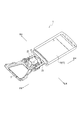
- FIG. 1 is a perspective view of a lower part of a vehicle body including a vehicle-mounted structure for a non-contact power receiving device according to an embodiment of the present invention.
- FIG. 2 is a perspective view showing a state in which the front floor panel is removed from FIG.
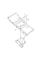
- FIG. 3 is an exploded perspective view showing the front floor panel shown in FIG. 1 and a junction box attached to the lower side of the front floor panel.
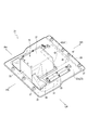
- FIG. 4 is a perspective view showing a non-contact power receiving apparatus according to an embodiment of the present invention.
- 5 is a cross-sectional view taken along the line BB in FIG. 6 is a cross-sectional view taken along the line AA in FIG.
- FIG. 7 is a cross-sectional view showing the air flow in the vicinity of the non-contact power receiving apparatus, and corresponds to FIG.
- FR is the front of the vehicle
- RR is the rear of the vehicle
- RH is the right side of the vehicle
- LH is the left side of the vehicle.
- a front compartment is formed in the front portion of the vehicle body 1, and a subframe 3 is disposed in the lower portion of the front compartment.
- the subframe 3 is formed in a square shape in plan view, and a motor unit (not shown) serving as a vehicle drive source is attached to the subframe 3 via a mount member.
- the vehicle compartment is located behind the vehicle in the front compartment. Between these front compartments and the passenger compartment, a dash panel (not shown) extending upward from the front end of the front floor panel 5 is disposed.
- a floor tunnel portion 7 formed in a hat shape protruding upward is extended in the front-rear direction at the vehicle width direction center portion of the front floor panel 5.
- the floor tunnel portion 7 includes an upper surface 9 on the upper side and a pair of left and right side surfaces 11, 11 extending downward from both left and right ends of the upper surface 9.
- a junction box 13 electrical component container
- a high-voltage wire harness 15 for transmitting power from a battery, which will be described later, to the motor unit extends along the front-rear direction.
- the wire harness 15 is routed through the inside of the floor tunnel portion 7.
- a rear floor panel (not shown) is joined to the rear of the front floor panel 5 and a battery case 17 that houses a battery is disposed below the rear floor panel.
- the battery case 17 in FIG. 1 shows a lower case 19, and the upper opening of the lower case is closed by an upper case (not shown).
- a non-contact power receiving device 21 is disposed between the subframe 3 and the battery case 17.
- the non-contact power receiving device 21 receives power supplied from a power feeding device arranged in a power supply stand or the like (not shown) and charges a battery mounted on the vehicle.
- the non-contact power receiving device 21 includes a power receiving side coil unit 23 disposed on the lower side and formed in a plate shape with a rectangular shape in plan view, and the power receiving side coil unit 23. And a junction box 13 (electrical component container) attached to the front side of the upper surface 23a.
- the battery is electrically connected to a power receiving side coil 49 described later, and stores the power transmitted from the power feeding side coil of the power feeding device.
- a front mounting surface 25 is formed at the front end of the power receiving side coil unit 23.
- the front mounting surface 25 is coupled to the lower surface of the rear end of the subframe 3 with a bolt via a disk-shaped protruding portion 27 protruding upward.
- a rear mounting surface 29 is formed at the rear end.
- the rear mounting surface 29 is fastened to the lower surface of the front end of the battery case 17 with a bolt via a disk-shaped protruding portion 27 that protrudes upward.
- a pair of mounting brackets 31 extending in the front-rear direction are joined to the left and right sides of the power receiving side coil unit 23.
- a bolt 33 projecting upward is coupled to the mounting bracket 31.
- the junction box 13 (electrical component container) is formed in a rectangular parallelepiped shape. Specifically, a front wall 35 disposed on the front side of the vehicle, an upper wall 37 disposed on the upper side, a pair of side walls 39, 39 disposed on the left and right sides, and a rear wall 41 disposed on the rear side of the vehicle. And.
- the rear wall 41 is formed in a vertical wall portion 43 that extends substantially vertically along the vertical direction.
- the junction box 13 is mounted on the front side of the upper surface 23 a of the power receiving side coil unit 23.
- a rectifier 45 (electrical component) is accommodated in the junction box 13.
- the rear side (indicated by a two-dot chain line) on which the junction box 13 is not mounted is formed on a rising airflow generation surface 47 having a rectangular shape in plan view.
- a portion of the front portion or the rear portion of the upper surface 23 a of the power receiving side coil unit 23 on the side where the junction box 13 is not mounted is used as an ascending air flow generation surface 47 in which the rising air current is generated by the heat of the power receiving side coil 49.
- a power receiving side coil 49 is accommodated in the power receiving side coil unit 23.
- the updraft generating surface 47 is also heated, so that the air 67 heated upward from the updraft generating surface 47 rises.
- the power receiving side coil unit 23 is dissipated.
- the left and right lower ends of the floor tunnel portion 7 have tunnel members 51 whose upper sides are open.
- the tunnel member 51 is joined to the front floor panel 5 to form a closed section 53.
- the receiving side coil unit 23 is arrange
- the power receiving side coil unit 23 includes a flat coil base 55, a power receiving side coil 49 coupled to the lower surface of the coil base 55, and the coil base 55 and the power receiving side coil 49.
- a coil cover 57 disposed on the lower side.
- the coil cover 57 has a recess 59 whose central portion is recessed downward with respect to the peripheral edge portion 57a.
- the power receiving side coil unit 23 is configured by fastening the peripheral edge 57a of the coil cover 57 to the coil base 55 with bolts.
- the power receiving side coil 49 generates heat by receiving the power transmitted from the power feeding side coil in a non-contact manner.
- the mounting bracket 31 of the power receiving side coil unit 23 is fastened with bolts 33 to the bottom surface 51 a of the tunnel member that is a part of the floor tunnel portion 7.
- the closed tunnel section 61 is formed by the floor tunnel section 7 and the power receiving side coil unit 23.
- the junction box 13 is attached to the upper surface 23 a of the power receiving side coil unit 23. Therefore, the junction box 13 is accommodated inside the closed cross-section 61 composed of the floor tunnel portion 7 and the power receiving side coil unit 23.
- a battery is arranged on the opposite side of the junction box 13 in the vehicle front-rear direction with the updraft generating surface 47 as the center.
- the battery case 17 is arranged on the rear side of the ascending air flow generation surface 47. That is, the junction box 13 and the battery case 17 are spaced apart in the front-rear direction by the length of the updraft generation surface 47.
- a harness connect portion 63 is disposed on the rear wall 41 (vertical wall portion 43) of the junction box 13.
- a wire harness 65 extending from the battery of the battery case 17 is connected to the harness connect portion 63.
- a high-voltage wire harness 15 routed from the motor unit in the front of the vehicle is connected to the front surface of the battery case 17.
- a portion where the junction box 13 is arranged and a rising airflow generating surface 47 exposing a portion corresponding to the power receiving side coil 49 are formed.
- the updraft generating surface 47 becomes hotter than the upper surface of the junction box 13.
- the updraft generating surface 47 When the power receiving side coil 49 generates heat, the updraft generating surface 47 also generates heat, and the heated air 67 moves upward from the updraft generating surface 47 to the floor tunnel portion 7.
- the air 67 that rises sequentially hits the floor tunnel portion 7, so that the air pressure becomes higher than the upper part of the junction box 13. That is, a pressure gradient is formed above the power receiving side coil unit 23 by the high pressure portion corresponding to the upper side of the rising air flow generation surface 47 and the low pressure portion corresponding to the upper side of the junction box 13.
- the air 67 moved upward from the ascending air flow generation surface 47 changes the flow direction to the upper side of the junction box 13 where the atmospheric pressure is low as indicated by the arrow, and passes through the upper side of the junction box 13 by natural convection and the floor tunnel portion. 7 flows inward toward the front of the vehicle.
- the high-temperature air 67 rises from the rising air flow generation surface 47 and then is discharged from the motor room through the upper portion of the junction box 13 by natural convection.
- the vehicle-mounted structure of the contactless power receiving device includes a power receiving side coil 49 that is disposed below the floor tunnel portion 7 of the vehicle and receives power transmitted from the power feeding side coil in a contactless manner. And a junction box 13 (electrical component container) mounted on the front side in the vehicle front-rear direction on the upper surface of the power receiving side coil unit 23.
- the power receiving side coil unit 23 includes a rectifier 45 (electrical component).
- the floor tunnel portion 7 and the power receiving side coil unit form a closed cross section 61 when viewed from the front of the vehicle.
- the junction box 13 is housed inside the closed cross section 61 and the junction box 13 is It is arranged near the front side in the vehicle front-rear direction on the upper surface 23 a of the side coil unit 23, the portion corresponding to the power receiving side coil 49 is exposed on the upper surface 23 a of the power receiving side coil unit 23, and rises due to the heat of the power receiving side coil 49.
- An updraft generating surface 47 for generating an airflow was configured.
- the air 67 that rises sequentially hits the floor tunnel portion 7, so that the air pressure becomes higher than the upper part of the junction box 13. That is, a pressure gradient is formed above the power receiving side coil unit 23 by the high pressure portion corresponding to the upper side of the rising air flow generation surface 47 and the low pressure portion corresponding to the upper side of the junction box 13.
- the hot air 67 moved upward from the updraft generating surface 47 changes the flow direction to the upper side of the junction box 13 where the atmospheric pressure is low, passes through the upper side of the junction box 13 by the natural convection, and enters the inside of the floor tunnel portion 7. Flows toward the front of the vehicle.
- the power receiving side coil unit 23 disposed in the closed cross section 61 is radiated using natural convection, so that heat is not trapped in the closed cross section 61 and the power receiving side coil unit 23 is downsized. 23, the temperature rise of the power receiving side coil 49 can be suppressed.
- a battery (battery case 17) that is electrically connected to the power receiving side coil 49 and stores the power transmitted from the power feeding side coil is connected to the power receiving side coil unit 23 in the front or rear direction of the vehicle.
- the junction box 13 is disposed on the rear side where the junction box 13 is not disposed.
- a side surface of the junction box 13 on the side of the rising air flow generation surface 47 is formed on the vertical wall portion 43, and a harness connect portion 63 for connecting a wire harness 65 extending from the battery to the vertical wall portion 43.
- the side surface of the junction box 13 is the vertical wall portion 43
- the work of connecting the wire harness 65 from the battery to the harness connect portion 63 becomes efficient.
- the vertical wall portion 43 can increase the area of the ascending air flow generation surface 47, and thus the heat dissipation efficiency of the power receiving side coil unit 23. Will improve.
- the rear side of the upper surface 23 a of the power receiving side coil unit 23 is set as the updraft generating surface 47.
- the front side is set as the updraft generating surface 47, and the battery case 17 is arranged in front of the updraft generating surface 47. Good.
- the present invention is applied to a vehicle-mounted structure of a non-contact power receiving device including a power receiving side coil that receives power transmitted from a power feeding side coil in a non-contact manner.
Landscapes
- Engineering & Computer Science (AREA)
- Power Engineering (AREA)
- Transportation (AREA)
- Mechanical Engineering (AREA)
- Life Sciences & Earth Sciences (AREA)
- Sustainable Development (AREA)
- Sustainable Energy (AREA)
- Chemical & Material Sciences (AREA)
- Combustion & Propulsion (AREA)
- Electric Propulsion And Braking For Vehicles (AREA)
- Current-Collector Devices For Electrically Propelled Vehicles (AREA)
- Arrangement Or Mounting Of Propulsion Units For Vehicles (AREA)
Abstract
Description
ここで、上昇気流発生面の上方部分は、順次に上昇してくる空気がフロアトンネル部に当たるため、電装部品容器の上方部分よりも、気圧が高くなっている。即ち、受電側コイルユニットの上方には、上昇気流発生面の上方に対応する高圧部と、電装部品容器の上方に対応する低圧部と、によって気圧勾配が形成される。
ここで、上昇気流発生面47の上方部分は、順次に上昇してくる空気67がフロアトンネル部7に当たるため、ジャンクションボックス13の上方部分よりも、気圧が高くなる。即ち、受電側コイルユニット23の上方には、上昇気流発生面47の上方に対応する高圧部と、ジャンクションボックス13の上方に対応する低圧部と、によって気圧勾配が形成される。
このように、閉断面部61内に配置された受電側コイルユニット23を自然対流を用いて放熱することにより、閉断面部61内に熱が篭もることなく、小型化した受電側コイルユニット23で受電側コイル49の温度上昇を抑制できる。
7 フロアトンネル部
13 ジャンクションボックス(電装部品容器)
23 受電側コイルユニット
23a 上面
43 垂直壁部
45 整流器(電装部品)
47 上昇気流発生面
49 受電側コイル
61 閉断面部
63 ハーネスコネクト部
65 ワイヤハーネス
Claims (3)
- 車両のフロアトンネル部の下側に配設され、給電側コイルから送電される電力を非接触で受電する受電側コイルを有する受電側コイルユニットと、
電装部品を収容し、前記受電側コイルユニットの上面における車両前後方向前側または後側に搭載される電装部品容器と、を備え、
前記フロアトンネル部と受電側コイルユニットとで車両正面視で閉断面部を形成し、この閉断面部の内方に前記電装部品容器を収容すると共に、
前記電装部品容器を、
前記受電側コイルユニットの上面における車両前後方向前側または後側のうち、いずれか一方へ寄せて配し、
前記受電側コイルユニットの上面に前記受電側コイルに対応する部位を露呈させて、受電側コイルの熱で上昇気流が発生する上昇気流発生面を構成したことを特徴とする非接触受電装置の車載構造。 - 前記受電側コイルと電気的に接続され前記給電側コイルから送電される電力を蓄電するバッテリを、受電側コイルユニットに対して車両前後方向前側または後側のうち、前記電装部品容器が配されない側に配したことを特徴とする請求項1に記載の非接触受電装置の車載構造。
- 前記電装部品容器における前記上昇気流発生面側の側面を垂直壁部に形成し、この垂直壁部に、前記バッテリから延在するハーネスを接続するハーネスコネクト部を設けたことを特徴とする請求項2記載の非接触受電装置の車載構造。
Priority Applications (10)
| Application Number | Priority Date | Filing Date | Title |
|---|---|---|---|
| US15/305,160 US9774213B2 (en) | 2014-04-23 | 2014-04-23 | Vehicle-mounting structure for wireless power reception device |
| JP2016514613A JP6179666B2 (ja) | 2014-04-23 | 2014-04-23 | 非接触受電装置の車載構造 |
| MX2016013593A MX351833B (es) | 2014-04-23 | 2014-04-23 | Estructura de montaje de vehículo para un dispositivo de recepción de energía sin contacto. |
| BR112016024809-0A BR112016024809B1 (pt) | 2014-04-23 | 2014-04-23 | Estrutura de montagem de veículo para um dispositivo de recebimento de energia sem fio |
| CN201480078185.6A CN106233405B (zh) | 2014-04-23 | 2014-04-23 | 非接触受电装置的车载构造 |
| KR1020167028630A KR101711800B1 (ko) | 2014-04-23 | 2014-04-23 | 비접촉 수전 장치의 차량 탑재 구조 |
| EP14889982.6A EP3136406B1 (en) | 2014-04-23 | 2014-04-23 | Vehicle-mounting structure for wireless power reception device |
| RU2016145581A RU2615505C1 (ru) | 2014-04-23 | 2014-04-23 | Монтируемая на транспортном средстве конструкция для устройства беспроводного приёма энергии |
| MYPI2016703792A MY162888A (en) | 2014-04-23 | 2014-04-23 | Vehicle-mounting structure for wireless power reception device |
| PCT/JP2014/061444 WO2015162725A1 (ja) | 2014-04-23 | 2014-04-23 | 非接触受電装置の車載構造 |
Applications Claiming Priority (1)
| Application Number | Priority Date | Filing Date | Title |
|---|---|---|---|
| PCT/JP2014/061444 WO2015162725A1 (ja) | 2014-04-23 | 2014-04-23 | 非接触受電装置の車載構造 |
Publications (1)
| Publication Number | Publication Date |
|---|---|
| WO2015162725A1 true WO2015162725A1 (ja) | 2015-10-29 |
Family
ID=54331914
Family Applications (1)
| Application Number | Title | Priority Date | Filing Date |
|---|---|---|---|
| PCT/JP2014/061444 Ceased WO2015162725A1 (ja) | 2014-04-23 | 2014-04-23 | 非接触受電装置の車載構造 |
Country Status (10)
| Country | Link |
|---|---|
| US (1) | US9774213B2 (ja) |
| EP (1) | EP3136406B1 (ja) |
| JP (1) | JP6179666B2 (ja) |
| KR (1) | KR101711800B1 (ja) |
| CN (1) | CN106233405B (ja) |
| BR (1) | BR112016024809B1 (ja) |
| MX (1) | MX351833B (ja) |
| MY (1) | MY162888A (ja) |
| RU (1) | RU2615505C1 (ja) |
| WO (1) | WO2015162725A1 (ja) |
Cited By (4)
| Publication number | Priority date | Publication date | Assignee | Title |
|---|---|---|---|---|
| JP2017229180A (ja) * | 2016-06-23 | 2017-12-28 | 本田技研工業株式会社 | 電源装置及び輸送機器 |
| EP3293030A1 (en) * | 2016-09-07 | 2018-03-14 | Thunder Power New Energy Vehicle Development Company Limited | Placement of battery elements in tunnel |
| RU2669241C1 (ru) * | 2016-09-05 | 2018-10-09 | Тойота Дзидося Кабусики Кайся | Автомобиль |
| RU2693775C1 (ru) * | 2017-12-27 | 2019-07-04 | Тойота Дзидося Кабусики Кайся | Транспортное средство |
Families Citing this family (10)
| Publication number | Priority date | Publication date | Assignee | Title |
|---|---|---|---|---|
| DE102016203209B4 (de) * | 2016-02-29 | 2020-11-19 | Ford Global Technologies, Llc | Zumindest teilweise elektrisch betreibbares Kraftfahrzeug |
| KR101926934B1 (ko) * | 2016-12-12 | 2019-03-08 | 현대자동차주식회사 | 고전압 정션블록의 장착구조 |
| JP6819476B2 (ja) * | 2017-06-16 | 2021-01-27 | トヨタ自動車株式会社 | 車両前部構造 |
| JP6541724B2 (ja) * | 2017-07-10 | 2019-07-10 | 株式会社Subaru | 自動車車両 |
| JP6794949B2 (ja) * | 2017-07-13 | 2020-12-02 | トヨタ自動車株式会社 | 車両前部構造 |
| GB2577568A (en) | 2018-09-28 | 2020-04-01 | Bombardier Primove Gmbh | Inductive power transfer pad comprising an airflow generating system, arrangement for an inductive power transfer and method for cooling an inductive power |
| DE102019113700A1 (de) * | 2019-05-22 | 2020-11-26 | Bayerische Motoren Werke Aktiengesellschaft | Gruppe von Kraftfahrzeugen mit einem Batterieantriebsfahrzeug und/oder einem Hybridantriebsfahrzeug und/oder einem Brennstoffzellenantriebsfahrzeug und/oder einem Verbrennungsmotorantriebsfahrzeug |
| KR102238042B1 (ko) * | 2019-10-01 | 2021-04-09 | 현대자동차주식회사 | 고전압 배터리의 케이스 구조 |
| JP7489452B2 (ja) * | 2020-04-28 | 2024-05-23 | 日産自動車株式会社 | 充電車両のワイヤハーネス配索構造 |
| JP7481235B2 (ja) * | 2020-11-19 | 2024-05-10 | 本田技研工業株式会社 | 車体下部構造 |
Citations (7)
| Publication number | Priority date | Publication date | Assignee | Title |
|---|---|---|---|---|
| JPH10109548A (ja) * | 1996-10-09 | 1998-04-28 | Suzuki Motor Corp | 電気自動車のバッテリ取付構造 |
| JP2005306104A (ja) * | 2004-04-19 | 2005-11-04 | Nissan Motor Co Ltd | 燃料電池自動車 |
| WO2012105040A1 (ja) * | 2011-02-04 | 2012-08-09 | トヨタ自動車株式会社 | 車両および外部給電装置 |
| JP2012244722A (ja) * | 2011-05-18 | 2012-12-10 | Toyota Motor Corp | 二次コイルユニットおよび電力伝送システム |
| WO2013046366A1 (ja) * | 2011-09-28 | 2013-04-04 | トヨタ自動車株式会社 | 受電装置、送電装置および電力伝送システム |
| JP2013112047A (ja) * | 2011-11-25 | 2013-06-10 | Toyota Motor Corp | 車両 |
| JP2013154815A (ja) * | 2012-01-31 | 2013-08-15 | Toyota Motor Corp | 車両および電力伝送システム |
Family Cites Families (15)
| Publication number | Priority date | Publication date | Assignee | Title |
|---|---|---|---|---|
| US20050120715A1 (en) * | 1997-12-23 | 2005-06-09 | Christion School Of Technology Charitable Foundation Trust | Heat energy recapture and recycle and its new applications |
| JP4306229B2 (ja) * | 2002-04-03 | 2009-07-29 | タカタ株式会社 | 衝突検出装置及び安全装置 |
| RU2461946C1 (ru) * | 2008-10-09 | 2012-09-20 | Тойота Дзидося Кабусика Кайся | Устройство бесконтактного получения энергии и транспортное средство, содержащее такое устройство |
| RU2408476C2 (ru) * | 2009-01-20 | 2011-01-10 | Государственное научное учреждение Всероссийский научно-исследовательский институт электрификации сельского хозяйства Российской академии сельскохозяйственных наук (ГНУ ВИЭСХ Россельхозакадемии) | Способ беспроводной передачи электрической энергии и устройство для его осуществления (варианты) |
| JP5531626B2 (ja) | 2009-05-26 | 2014-06-25 | 日産自動車株式会社 | 車両のバッテリアセンブリ冷却構造、および、ウォータージャケット付きバッテリアセンブリ |
| WO2011116394A1 (en) * | 2010-03-19 | 2011-09-22 | Fisker Automotive, Inc. | Wireless charging device for electric and plug-in hybrid vehicles |
| JP2012121375A (ja) * | 2010-12-06 | 2012-06-28 | Mazda Motor Corp | 車両のバッテリ配設構造 |
| US9272630B2 (en) | 2011-05-27 | 2016-03-01 | Samsung Electronics Co., Ltd. | Electronic device and method for transmitting and receiving wireless power |
| JP6012188B2 (ja) | 2012-02-06 | 2016-10-25 | 矢崎総業株式会社 | コイルユニット |
| US9566851B2 (en) * | 2012-09-19 | 2017-02-14 | Nissan Motor Co., Ltd. | Mounting structure of high voltage unit for electric vehicle |
| MY162046A (en) * | 2013-03-29 | 2017-05-31 | Nissan Motor | Non-contact power supply system |
| RU2596003C1 (ru) * | 2013-04-12 | 2016-08-27 | Ниссан Мотор Ко., Лтд. | Устройство бесконтактной подачи электрической мощности |
| EP2985162B1 (en) * | 2013-04-12 | 2017-06-14 | Nissan Motor Co., Ltd. | Contactless power supply device |
| US9725004B2 (en) * | 2013-09-27 | 2017-08-08 | Nissan Motor Co., Ltd. | Vehicle mounting structure of contactless power reception device |
| CN105593053A (zh) * | 2013-09-27 | 2016-05-18 | 日产自动车株式会社 | 非接触受电装置的车载构造 |
-
2014
- 2014-04-23 JP JP2016514613A patent/JP6179666B2/ja active Active
- 2014-04-23 US US15/305,160 patent/US9774213B2/en active Active
- 2014-04-23 EP EP14889982.6A patent/EP3136406B1/en active Active
- 2014-04-23 MY MYPI2016703792A patent/MY162888A/en unknown
- 2014-04-23 WO PCT/JP2014/061444 patent/WO2015162725A1/ja not_active Ceased
- 2014-04-23 KR KR1020167028630A patent/KR101711800B1/ko not_active Expired - Fee Related
- 2014-04-23 RU RU2016145581A patent/RU2615505C1/ru active
- 2014-04-23 BR BR112016024809-0A patent/BR112016024809B1/pt not_active IP Right Cessation
- 2014-04-23 MX MX2016013593A patent/MX351833B/es active IP Right Grant
- 2014-04-23 CN CN201480078185.6A patent/CN106233405B/zh active Active
Patent Citations (7)
| Publication number | Priority date | Publication date | Assignee | Title |
|---|---|---|---|---|
| JPH10109548A (ja) * | 1996-10-09 | 1998-04-28 | Suzuki Motor Corp | 電気自動車のバッテリ取付構造 |
| JP2005306104A (ja) * | 2004-04-19 | 2005-11-04 | Nissan Motor Co Ltd | 燃料電池自動車 |
| WO2012105040A1 (ja) * | 2011-02-04 | 2012-08-09 | トヨタ自動車株式会社 | 車両および外部給電装置 |
| JP2012244722A (ja) * | 2011-05-18 | 2012-12-10 | Toyota Motor Corp | 二次コイルユニットおよび電力伝送システム |
| WO2013046366A1 (ja) * | 2011-09-28 | 2013-04-04 | トヨタ自動車株式会社 | 受電装置、送電装置および電力伝送システム |
| JP2013112047A (ja) * | 2011-11-25 | 2013-06-10 | Toyota Motor Corp | 車両 |
| JP2013154815A (ja) * | 2012-01-31 | 2013-08-15 | Toyota Motor Corp | 車両および電力伝送システム |
Non-Patent Citations (1)
| Title |
|---|
| See also references of EP3136406A4 * |
Cited By (5)
| Publication number | Priority date | Publication date | Assignee | Title |
|---|---|---|---|---|
| JP2017229180A (ja) * | 2016-06-23 | 2017-12-28 | 本田技研工業株式会社 | 電源装置及び輸送機器 |
| RU2669241C1 (ru) * | 2016-09-05 | 2018-10-09 | Тойота Дзидося Кабусики Кайся | Автомобиль |
| EP3293030A1 (en) * | 2016-09-07 | 2018-03-14 | Thunder Power New Energy Vehicle Development Company Limited | Placement of battery elements in tunnel |
| US10597083B2 (en) | 2016-09-07 | 2020-03-24 | Thunder Power Electric Vehicle Limited | Placement of battery elements in tunnel |
| RU2693775C1 (ru) * | 2017-12-27 | 2019-07-04 | Тойота Дзидося Кабусики Кайся | Транспортное средство |
Also Published As
| Publication number | Publication date |
|---|---|
| MY162888A (en) | 2017-07-20 |
| KR20160135279A (ko) | 2016-11-25 |
| US9774213B2 (en) | 2017-09-26 |
| BR112016024809B1 (pt) | 2022-11-16 |
| RU2615505C1 (ru) | 2017-04-05 |
| CN106233405A (zh) | 2016-12-14 |
| MX351833B (es) | 2017-10-31 |
| MX2016013593A (es) | 2017-01-26 |
| KR101711800B1 (ko) | 2017-03-02 |
| EP3136406A1 (en) | 2017-03-01 |
| JP6179666B2 (ja) | 2017-08-16 |
| BR112016024809A2 (pt) | 2017-08-15 |
| JPWO2015162725A1 (ja) | 2017-04-13 |
| EP3136406A4 (en) | 2017-04-26 |
| CN106233405B (zh) | 2017-12-05 |
| US20170040836A1 (en) | 2017-02-09 |
| EP3136406B1 (en) | 2019-01-16 |
Similar Documents
| Publication | Publication Date | Title |
|---|---|---|
| JP6179666B2 (ja) | 非接触受電装置の車載構造 | |
| US8757304B2 (en) | Electric vehicle | |
| EP2772394B1 (en) | Wiring protective cover structure for electric vehicle | |
| JP6107938B2 (ja) | 自動車における発熱電気部品の配設構造 | |
| CN103930300B (zh) | 电动机动车 | |
| CN107776390B (zh) | 车辆 | |
| CN105730184B (zh) | 电力控制单元及电气器件 | |
| CN103101490A (zh) | 电动机动车的电力控制单元支承结构 | |
| JP6817248B2 (ja) | 電気自動車における電気機器の配置構造 | |
| CN103101424B (zh) | 动力控制单元的保护构造 | |
| JP2013103587A (ja) | 電気自動車用パワーコントロールユニットの保護構造 | |
| JP2016141353A (ja) | バッテリユニット | |
| JP5292524B1 (ja) | 電気自動車のパワーコントロールユニット | |
| JP2018024376A (ja) | 車両 | |
| JP2015071397A (ja) | 電動車のワイヤハーネス配索構造 | |
| JP2014139057A (ja) | 車両の電装部品搭載装置 | |
| JP6164068B2 (ja) | 車両の電装品配置構造 | |
| WO2014162887A1 (ja) | 自動車における電力変換機の配設構造 |
Legal Events
| Date | Code | Title | Description |
|---|---|---|---|
| 121 | Ep: the epo has been informed by wipo that ep was designated in this application |
Ref document number: 14889982 Country of ref document: EP Kind code of ref document: A1 |
|
| ENP | Entry into the national phase |
Ref document number: 2016514613 Country of ref document: JP Kind code of ref document: A |
|
| ENP | Entry into the national phase |
Ref document number: 20167028630 Country of ref document: KR Kind code of ref document: A |
|
| REEP | Request for entry into the european phase |
Ref document number: 2014889982 Country of ref document: EP |
|
| WWE | Wipo information: entry into national phase |
Ref document number: MX/A/2016/013593 Country of ref document: MX Ref document number: 2014889982 Country of ref document: EP |
|
| WWE | Wipo information: entry into national phase |
Ref document number: 15305160 Country of ref document: US |
|
| WWE | Wipo information: entry into national phase |
Ref document number: IDP00201607139 Country of ref document: ID |
|
| NENP | Non-entry into the national phase |
Ref country code: DE |
|
| REG | Reference to national code |
Ref country code: BR Ref legal event code: B01A Ref document number: 112016024809 Country of ref document: BR |
|
| ENP | Entry into the national phase |
Ref document number: 2016145581 Country of ref document: RU Kind code of ref document: A |
|
| ENP | Entry into the national phase |
Ref document number: 112016024809 Country of ref document: BR Kind code of ref document: A2 Effective date: 20161024 |